WO2012070177A1 - 光ファイバ着色心線 - Google Patents
光ファイバ着色心線 Download PDFInfo
- Publication number
- WO2012070177A1 WO2012070177A1 PCT/JP2011/005453 JP2011005453W WO2012070177A1 WO 2012070177 A1 WO2012070177 A1 WO 2012070177A1 JP 2011005453 W JP2011005453 W JP 2011005453W WO 2012070177 A1 WO2012070177 A1 WO 2012070177A1
- Authority
- WO
- WIPO (PCT)
- Prior art keywords
- coating layer
- optical fiber
- layer
- colored
- secondary coating
- Prior art date
Links
Images

Classifications
-
- G—PHYSICS
- G02—OPTICS
- G02B—OPTICAL ELEMENTS, SYSTEMS OR APPARATUS
- G02B6/00—Light guides; Structural details of arrangements comprising light guides and other optical elements, e.g. couplings
- G02B6/02—Optical fibres with cladding with or without a coating
- G02B6/02395—Glass optical fibre with a protective coating, e.g. two layer polymer coating deposited directly on a silica cladding surface during fibre manufacture
-
- G—PHYSICS
- G02—OPTICS
- G02B—OPTICAL ELEMENTS, SYSTEMS OR APPARATUS
- G02B6/00—Light guides; Structural details of arrangements comprising light guides and other optical elements, e.g. couplings
- G02B6/44—Mechanical structures for providing tensile strength and external protection for fibres, e.g. optical transmission cables
- G02B6/4479—Manufacturing methods of optical cables
- G02B6/4482—Code or colour marking
Definitions
- the present invention relates to an optical fiber colored core housed in an optical fiber cable, and specifically relates to an optical fiber colored core wire that suppresses an increase in transmission loss of an optical fiber due to a use environment or deterioration over time.
- the present invention relates to an optical fiber colored core wire in which transmission loss does not easily increase over a long period even in water immersion.
- the outer periphery is immediately coated with a coating resin, and a colored layer is provided for identification.
- a coating resin an ultraviolet curable resin is mainly used. Urethane acrylate or epoxy acrylate is used as the ultraviolet curable resin.
- the optical fiber In optical fiber, transmission loss increases due to various external stresses and microbends caused by it. Therefore, in order to protect the optical fiber from such external stress, generally, the optical fiber is coated with a two-layer structure of a soft layer and a hard layer.
- the inner layer in contact with the quartz glass is a buffer layer by using a soft resin having a relatively low elastic modulus (hereinafter referred to as a primary layer), and the outer layer is a protective layer by using a hard resin having a relatively high Young's modulus ( Hereinafter, secondary layer).
- the elastic modulus of the primary layer is 3 MPa or less
- the secondary layer is a resin having an elastic modulus of 500 MPa or more.
- a liquid ultraviolet curable resin is applied to a quartz glass optical fiber heated and melted and drawn by a drawing furnace from a preform mainly composed of silica glass using a coating die, and subsequently to this.
- the ultraviolet curable resin is cured by irradiating with ultraviolet rays.
- an optical fiber is manufactured by covering an optical fiber with a primary layer and a secondary layer.
- an optical fiber colored core is manufactured by covering the outer periphery of the obtained optical fiber with a coating layer made of a colored resin.
- optical fiber strand a glass optical fiber coated with a primary layer and a secondary layer
- optical fiber strand the outer periphery of the optical fiber strand is further coated with a coating layer made of a colored resin.
- An optical fiber colored core wire and a plurality of optical fiber colored core wires arranged on a plane and collectively covered with a tape resin are referred to as an optical fiber tape core wire.
- the elastic modulus of the colored layer is set to the secondary layer. It has been proposed to make it higher than the elastic modulus and to make the glass transition temperature of the colored layer higher than the glass transition temperature of the secondary layer.
- JP 2002-255590 A Japanese Patent No. 2925099
- An object of the present invention is to provide an optical fiber colored core wire in which transmission loss hardly increases even when immersed in water.
- the present invention provides an optical fiber colored core, which is a glass optical fiber, a primary coating layer that covers the glass optical fiber, and a secondary coating that covers the primary coating layer. And a colored layer covering the secondary coating layer, the laminate having the secondary coating layer and the colored layer covering the secondary coating layer with respect to the thermal expansion coefficient of the secondary coating layer Of the laminate with respect to the glass transition temperature of the dynamic viscoelasticity in the temperature range of ⁇ 100 ° C. to 150 ° C. of the secondary coating layer.
- the glass transition temperature ratio is 0.96 or more and 1.03 or less.
- an optical fiber colored core wire in which transmission loss hardly increases even when used in a state of being immersed in water.
- an optical fiber strand in which a primary layer and a secondary layer are coated on a glass optical fiber is manufactured, and an optical fiber colored core is formed by coating the optical fiber strand with a colored layer.
- the resin used for each coating layer is an ultraviolet curable resin.
- an optical fiber ribbon can be obtained by arranging a plurality of optical fiber colored cores in parallel on a flat surface and covering them with a tape resin made of an ultraviolet curable resin.
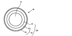
- FIG. 1 is a cross-sectional view of an optical fiber 14 according to an embodiment of the present invention
- FIG. 2 is a cross-sectional view of an optical fiber colored core wire 16 according to an embodiment of the present invention
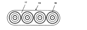
- FIG. 1 is a cross-sectional view of an optical fiber ribbon 18 according to an embodiment of the present invention.
- an optical fiber 14 includes a glass optical fiber 11 and a coating layer 20 that covers the glass optical fiber 11.
- the coating layer 20 includes a primary layer (hereinafter also referred to as “primary coating layer”) 12 that covers the glass optical fiber 11 and a secondary layer (hereinafter referred to as “secondary coating layer”) that covers the primary coating layer 12. 13). Since the primary coating layer 12 is a soft resin, its elastic modulus is relatively low. On the other hand, since the secondary coating layer 13 is a hard resin, the elastic modulus is higher than that of the primary coating layer 12. Since the secondary coating layer 13 is formed on the primary coating layer 12, the coating layer 20 can be said to be a laminate in which the primary coating layer 12 and the secondary coating layer 13 are laminated in this order in a cylindrical shape. .
- the optical fiber colored core wire 16 includes a glass optical fiber 11 and a coating layer 22 that covers the glass optical fiber 11.
- the coating layer 22 includes the primary coating layer 12, the secondary coating layer 13, and a colored layer 15 that covers the secondary coating layer 13. That is, the optical fiber colored core wire 16 has a structure in which the optical fiber 14 is covered with the colored layer 15.
- the coating layer 22 includes the primary coating layer 12 and the secondary coating layer. It can be said that 13 and the colored layer 15 are laminated in this order in a cylindrical shape.
- reference numeral 21 denotes a laminate of the secondary coating layer 13 and the colored layer 15 formed so as to cover the secondary coating layer 13.
- an optical fiber ribbon 18 includes a plurality of optical fiber colored cores 16 arranged in a plane and a tape resin 17 covering the plurality of optical fiber colored cores 16 arranged in a plane.
- the coating resin used as the raw material of the primary coating layer 12 and the secondary coating layer 13 of the optical fiber 14 and the ultraviolet curable resin used as the colored resin used as the raw material of the colored layer 15 of the optical fiber colored core wire 16 are, for example, Mainly include oligomers, dilution monomers, photoinitiators, silane coupling agents, sensitizers, pigments and various additives.
- oligomer polyether urethane acrylate, epoxy acrylate, polyester acrylate, silicone acrylate and the like are mainly used.
- a monofunctional monomer or a polyfunctional monomer is used as the dilution monomer.
- the colored layer 15 is formed on the outer periphery of the optical fiber 14 including the glass optical fiber 11 and the primary coating layer 12 and the secondary coating layer 13 formed on the glass optical fiber 11.
- the ratio of the thermal expansion coefficient of the laminate 21 of the secondary coating layer 13 and the colored layer 15 to the thermal expansion coefficient of the secondary coating layer 13 is 0.98 or more and 1.03 or less. That is.
- Another feature of the present invention is that a laminate 21 of the secondary coating layer 13 and the colored layer 15 with respect to the glass transition temperature Tg of dynamic viscoelasticity in the temperature range of ⁇ 100 ° C. to 150 ° C. of the secondary coating layer 13.
- the ratio of the glass transition temperature Tg is 0.96 or more and 1.03 or less.
- the internal strain between the secondary coating layer as the secondary layer and the colored layer when immersed in water can be suppressed by the above two characteristics. That is, according to the optical fiber colored core wire of the present invention, due to the first feature, when the temperature change or the optical fiber colored core wire 16 is immersed in warm water, the secondary coating layer 13 and the colored layer 15 are similarly treated. It can be expanded and contracted, and the internal strain between the secondary coating layer 13 and the colored layer 15 can be reduced. Thereby, the shift
- the secondary coating layer 13 and the colored layer 15 both expand and contract in the same manner, so that the secondary coating is performed.
- the internal strain between the layer 13 and the colored layer 15 can be reduced. Therefore, it is possible to suppress the force for peeling the primary coating layer 12 from the glass optical fiber 11 at the interface between the glass optical fiber 11 and the primary coating layer 12 as the primary layer.
- the optical fiber colored core wire 16 when the optical fiber colored core wire 16 is immersed in water, the water passes through the colored layer 15 and enters the secondary coating layer 13 and the primary coating layer 12, and the glass optical fiber 11 and the primary coating layer 12.
- the part with weak adhesion at the interface may peel off and cause delamination.
- delamination occurs in this manner, osmotic pressure is generated to reduce the concentration in the delaminated portion due to the influence of osmotic pressure, and a large amount of water is taken in.
- the secondary coating layer 13 and the colored layer 15 By matching the glass transition temperature and the thermal expansion coefficient, it is possible to prevent water from being stored in the optical fiber colored core wire 16.
- Patent Document 1 by arranging the elastic modulus and glass transition temperature of the primary layer, the secondary layer, and the colored layer so as to increase from the inner side toward the outer side, an internal stress caused by the strain of each coating layer, etc. It is possible to alleviate the non-uniform transmission of the film and to suppress the peeling of blisters and the generation of blisters.
- the elastic modulus of the colored layer is higher than that of the secondary layer and the glass transition temperature of the colored layer is higher than that of the secondary layer, internal strain is likely to occur at the interface between the secondary layer and the colored layer.
- the cross-linking density of the colored layer is high and the cross-linking density of the secondary layer is low, when water enters the inside through the colored layer, the water that has entered the inside is dammed to the colored layer having a high cross-linking density, and coloring Difficult to get out of the layer. That is, conventionally, water enters the optical fiber colored core wire, but the intruded water is difficult to go outside.
- the glass transition temperature and the thermal expansion coefficient of the secondary coating layer 13 and the colored layer 15 are made approximately the same, thereby passing through the colored layer 15 and entering the optical fiber colored core wire 16. Even if water permeates, the permeated water easily passes through the colored layer 15.
- the secondary coating layer 13 and the colored layer 15 are similarly expanded and contracted by a temperature change, and for this reason, the heat of the secondary coating layer 13 and the colored layer 15 is reduced.
- the expansion coefficient and glass transition temperature are the same or substantially the same.
- the secondary coating layer 13 and the laminate 21 of the secondary coating layer 13 and the colored layer 15 have a large difference in thermal expansion coefficient and glass transition temperature between the colored layer 15 and the secondary coating layer 13.
- the thermal expansion coefficient and the glass transition temperature between the secondary coating layer 13 and the laminate 21 are greatly different.
- the thermal expansion coefficient and the glass transition temperature of the colored layer 15 and the secondary coating layer 13 are approximately the same, the thermal expansion coefficient and the glass transition temperature of the secondary coating layer 13 and the laminate 21 should be approximately the same. It is.
- it is important that both the secondary coating layer 13 and the colored layer 15 are expanded and contracted in the same manner, and the thermal expansion coefficient and the glass transition temperature of the secondary coating layer 13 and the colored layer 15 are the same.
- the thermal expansion coefficient and the glass transition temperature of the secondary coating layer 13 and the laminate 21 are linked to the thermal expansion coefficient and the glass transition temperature of the secondary coating layer 13 and the colored layer 15, In the present invention, whether the thermal expansion coefficient and the glass transition temperature of the secondary coating layer 13 are comparable to the thermal expansion coefficient and the glass transition temperature of the colored layer 15, the thermal expansion coefficients of the secondary coating layer 13 and the laminate 21. It is indirectly determined by using the glass transition temperature as an index.
- an optical fiber 14 in which the glass optical fiber 11 made of quartz glass in FIG. 1 is coated with a coating resin layer (coating layer 20) having two layers of a primary coating layer 12 and a secondary coating layer 13 is used.
- An ultraviolet curable resin was used as each resin.
- the ultraviolet curable resin contains an oligomer, a diluted monomer, a photoinitiator, a chain transfer agent, and an additive, and several types of optical fiber wires 14 were obtained by changing the constituent materials. Further, as shown in FIG.
- the optical fiber colored core 16 has a glass optical fiber 11 made of quartz glass having an outer diameter of 125 ⁇ m, an outer diameter of the primary coating layer 12 of 183 ⁇ m and 196 ⁇ m, and an outer diameter of the secondary coating layer 13.
- the colored layer 15 was coated in a separate process to obtain an optical fiber colored core wire 16 having an outer diameter of 255 ⁇ m.
- the outer diameter of the glass optical fiber 11 is usually 80 ⁇ m to 125 ⁇ m
- the outer diameter of the primary coating layer 12 is 120 ⁇ m to 200 ⁇ m
- the outer diameter of the secondary coating layer 13 the outer diameter of the secondary coating layer 13.
- the obtained optical fiber colored core wires 16 are arranged in parallel in four planes and collectively covered with a tape resin 17 made of an ultraviolet curable resin to obtain an optical fiber tape core wire 18.
- the adhesion between the glass optical fiber 11 and the primary coating layer 12 of the optical fiber 14 used in the present invention is 5N to 20N.
- 48th International Wire and Cable Symposium “Polymer coatings” For Optical fibers “Pullout force” is used. The speed is 5 mm / min.
- the colored layer 15 can be made substantially the same in thermal expansion coefficient as the secondary coating layer 13 by being composed of a composition equivalent to the coating resin used for the secondary coating layer 13. In this case, there is a concern about a decrease in the degree of curing of the ultraviolet curable resin used for the colored layer 15, but this can be adjusted by changing the type of the photoinitiator or increasing the amount of addition.
- an alkylphenone photopolymerization initiator or an acyl phosphine oxide photopolymerization initiator is added as a photoinitiator for the ultraviolet curable resin used in the colored layer.
- a monofunctional monomer such as isobornyl acrylate, it is possible to increase the elastic modulus without increasing the glass transition temperature.
- a method for obtaining the thermal expansion coefficient (volume expansion coefficient) will be described.
- a coated sample was prepared.
- One is a fiber sample (optical fiber strand 14 or optical fiber colored core wire 16) in which a coating layer (the coating layer 20 or the coating layer 22) is coated on a glass optical fiber.
- the other is a tube-coated sample consisting only of a coating layer (coating layer 20 or coating layer 22) obtained by removing a glass optical fiber from a fiber sample (optical fiber strand 14 or optical fiber colored core wire 16).
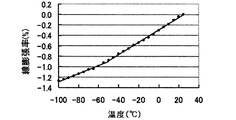
- the thermal expansion coefficient was measured using TMA thermomechanical analysis (Mettler Toledo TMA-40) in the longitudinal direction and the outer diameter direction.
- the measurement conditions are 0 applied load, temperature range -100 ° C to 100 ° C, temperature increase rate 10 ° C / min.
- the longitudinal direction is measured using a tube-coated sample in the tensile mode, and the outer diameter direction is measured. Measurement was performed in a compression mode with a glass optical fiber in a fiber sample. Since the linear expansion coefficient of the coating layer varies greatly in the vicinity of the glass transition point of the coating layer, the temperature range to be measured is preferably set to a range including the glass transition points of all the coating layers.
- FIG. 4 shows the relationship between the measured temperature in the longitudinal direction and the linear expansion coefficient
- FIG. 5 shows the relationship between the temperature in the outer diameter direction and the linear expansion coefficient.
- Each linear expansion coefficient was determined from the slope of the temperature range of ⁇ 50 to 25 ° C., that is, the measurement result changed linearly.
- the glass transition temperature of the primary coating layer 12 (primary layer) is as low as about ⁇ 50 ° C.
- the primary coating layer 12 (primary layer) of the tube-coated sample has a significantly lower elastic modulus than the secondary coating layer 13 (secondary layer) and the colored layer 15, and thus the coating layer 20
- the secondary coating layer 13 and the secondary coating layer 13 and the colored layer 15 of the coating layer 22 can freely expand and contract. That is, it can be said that the volume expansion coefficient of the coating layer 20 is substantially the same as the volume expansion coefficient of the secondary coating layer 13, and the volume expansion coefficient of the coating layer 22 is a laminate of the secondary coating layer 13 and the colored layer 15. It can be said that the volume expansion coefficient of 21 is almost the same.
- the respective volume thermal expansion coefficients can be obtained from the linear expansion coefficients of the secondary coating layer 13 and the laminate 21 using the formula 1).
- ⁇ s ⁇ SL + 2 ⁇ ⁇ SR 1
- ⁇ s Volumetric expansion coefficient of secondary coating layer 13 and laminate 21
- ⁇ SL linear expansion coefficient in the longitudinal direction of the secondary coating layer 13 and the laminate 21
- ⁇ SR linear expansion coefficient in the outer diameter direction of the secondary coating layer 13 and the laminate 21
- volume expansion coefficient calculated in this manner, in Table 1, in each example, the volume expansion coefficient for the secondary coating layer 13 is described in the “volume expansion coefficient of the secondary coating layer” column, and the laminate 21. The volume expansion coefficient is described in the “Volume expansion coefficient of laminate” column.
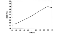
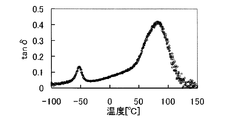
- the glass transition temperature Tg of the secondary coating layer 13 and the laminate 21 is measured using the DMA dynamic viscoelasticity test (TA company RSA3), and the temperature at which the maximum value of tan ⁇ appears as shown in FIG.
- the above tube-coated sample was measured by a tensile method under the conditions of 20 mm between marked lines, a frequency of 1 Hz, and a heating rate of 2 ° C./min.
- the tube-coated sample is measured in the temperature range of ⁇ 100 ° C. to 150 ° C., two tan ⁇ peaks appear on the low temperature side and the high temperature side.
- the low temperature side indicates the glass transition temperature of the primary coating layer 12 (primary layer)
- the high temperature side indicates the glass transition temperature of the secondary coating layer 13 and the colored layer 15.
- the glass transition temperature of the secondary coating layer 13 is described in the “Glass transition temperature of the secondary coating layer” column, and the laminate 21 The volume expansion coefficient is described in the “Glass transition temperature of the coating layer of the laminate” column.
- Transmission loss measurement method Using the manufactured optical fiber 14 and the optical fiber colored core wire 16, an optical fiber strand or colored core wire having a length of about 1 km was immersed in hot water at 60 ° C., and the transmission loss after the immersion was measured.
- the transmission loss was measured by using an optical pulse tester MW9076B manufactured by Anritsu Co., Ltd., and measuring the transmission loss with a wavelength of 1.55 ⁇ m in the longitudinal direction by the optical backscattering loss coefficient (OTDR). And after raising water temperature to 60 degreeC and immersing for 90 days, when it is recognized that the transmission loss is increasing 0.1 dB / km or more, it judges that there is no tolerance with respect to use environment, and in Table 1. Is marked with a cross.
- the optical fiber colored core wire of the present invention comprises a glass optical fiber coated with two coating layers of a primary coating layer as a primary layer and a secondary coating layer as a secondary layer.
- the ratio of thermal expansion coefficients is 0.98 or more and 1.03 or less, and the dynamics of the secondary coating layer 13 and the laminate 21 (secondary coating layer 13 + colored layer 15) in the temperature range of ⁇ 100 ° C. to 150 ° C.
- This is an optical fiber colored core having a viscoelastic glass transition temperature Tg ratio of 0.96 to 1.03. Therefore, as shown in Table 1, in this example, transmission loss does not increase even when immersed in warm water at 60 ° C. for 30 days, and transmission loss increases even when immersed in warm water at 60 ° C. for 90 days. No effect was obtained.
Landscapes
- Physics & Mathematics (AREA)
- General Physics & Mathematics (AREA)
- Optics & Photonics (AREA)
- Engineering & Computer Science (AREA)
- Manufacturing & Machinery (AREA)
- Optical Fibers, Optical Fiber Cores, And Optical Fiber Bundles (AREA)
- Surface Treatment Of Glass Fibres Or Filaments (AREA)
Priority Applications (4)
| Application Number | Priority Date | Filing Date | Title |
|---|---|---|---|
| EP11843901.7A EP2645143B1 (en) | 2010-11-24 | 2011-09-28 | Pigmented fiber optic cable core |
| CN201180056638.1A CN103229083B (zh) | 2010-11-24 | 2011-09-28 | 光纤着色芯线 |
| BR112013012253-6A BR112013012253B1 (pt) | 2010-11-24 | 2011-09-28 | Fibra óptica revestida e colorida e tira de fibra óptica |
| US13/754,985 US8639077B2 (en) | 2010-11-24 | 2013-01-31 | Colored coated optical fiber |
Applications Claiming Priority (2)
| Application Number | Priority Date | Filing Date | Title |
|---|---|---|---|
| JP2010261209A JP5041450B2 (ja) | 2010-11-24 | 2010-11-24 | 光ファイバ着色心線 |
| JP2010-261209 | 2010-11-24 |
Related Child Applications (1)
| Application Number | Title | Priority Date | Filing Date |
|---|---|---|---|
| US13/754,985 Continuation US8639077B2 (en) | 2010-11-24 | 2013-01-31 | Colored coated optical fiber |
Publications (1)
| Publication Number | Publication Date |
|---|---|
| WO2012070177A1 true WO2012070177A1 (ja) | 2012-05-31 |
Family
ID=46145551
Family Applications (1)
| Application Number | Title | Priority Date | Filing Date |
|---|---|---|---|
| PCT/JP2011/005453 WO2012070177A1 (ja) | 2010-11-24 | 2011-09-28 | 光ファイバ着色心線 |
Country Status (6)
Families Citing this family (11)
| Publication number | Priority date | Publication date | Assignee | Title |
|---|---|---|---|---|
| JP5255690B2 (ja) | 2011-12-27 | 2013-08-07 | 古河電気工業株式会社 | 光ファイバ着色心線、光ファイバテープ心線および光ファイバケーブル |
| JP5465741B2 (ja) | 2012-02-17 | 2014-04-09 | 古河電気工業株式会社 | 光ファイバ心線、光ファイバテープ心線および光ケーブル |
| AU2014265983B2 (en) * | 2013-05-14 | 2017-09-14 | Commscope Technologies Llc | Power/fiber hybrid cable |
| JP2015176015A (ja) * | 2014-03-17 | 2015-10-05 | 住友電気工業株式会社 | 光ファイバ着色心線 |
| US10908373B2 (en) * | 2016-09-30 | 2021-02-02 | Fujikura Ltd. | Optical fiber ribbon, optical fiber cable, and method of manufacturing optical fiber ribbon |
| JP6841836B2 (ja) | 2016-09-30 | 2021-03-10 | 株式会社フジクラ | 光ファイバ着色心線の製造方法および光ファイバケーブルの製造方法 |
| US10501370B2 (en) | 2017-12-07 | 2019-12-10 | Corning Incorporated | Method of applying an ink layer onto an optical fiber |
| JP7370995B2 (ja) * | 2018-09-13 | 2023-10-30 | 古河電気工業株式会社 | 光ファイバ心線及び光ファイバケーブル |
| WO2020096055A1 (ja) * | 2018-11-09 | 2020-05-14 | 住友電気工業株式会社 | 光ファイバ |
| JP2020140079A (ja) * | 2019-02-28 | 2020-09-03 | 住友電気工業株式会社 | 光ファイバ |
| KR102791365B1 (ko) * | 2019-06-18 | 2025-04-03 | 스미토모 덴키 고교 가부시키가이샤 | 광파이버 |
Citations (4)
| Publication number | Priority date | Publication date | Assignee | Title |
|---|---|---|---|---|
| JP2925099B2 (ja) | 1991-07-15 | 1999-07-26 | 住友電気工業株式会社 | 光ファイバ心線およびテープ状光ファイバ心線 |
| JP2001240433A (ja) * | 1999-12-21 | 2001-09-04 | Sumitomo Electric Ind Ltd | 被覆光ファイバ |
| JP2002255590A (ja) | 2001-02-28 | 2002-09-11 | Hitachi Cable Ltd | 着色光ファイバ |
| JP2004004423A (ja) * | 2002-04-05 | 2004-01-08 | Furukawa Electric Co Ltd:The | ファイバグレーティング用ガラス光ファイバ素線 |
Family Cites Families (17)
| Publication number | Priority date | Publication date | Assignee | Title |
|---|---|---|---|---|
| WO2002055447A2 (en) * | 2001-01-12 | 2002-07-18 | Dsm N.V. | Urethane-acrylic coatings for optical fiber |
| JP2003322775A (ja) | 2002-04-30 | 2003-11-14 | Furukawa Electric Co Ltd:The | 光ファイバ素線 |
| JP5220279B2 (ja) | 2006-03-23 | 2013-06-26 | 古河電気工業株式会社 | 光ファイバ素線 |
| US20110059236A1 (en) | 2006-03-23 | 2011-03-10 | Furukawa Electric Co., Ltd. | Optical fiber |
| JP2007272060A (ja) | 2006-03-31 | 2007-10-18 | Furukawa Electric Co Ltd:The | 光ファイバリボン芯線及び光ファイバケーブル |
| JP2007322893A (ja) | 2006-06-02 | 2007-12-13 | Furukawa Electric Co Ltd:The | 光ファイバ心線とその評価方法 |
| EP2048529B1 (en) | 2006-07-28 | 2018-10-24 | The Furukawa Electric Co., Ltd. | Optical fiber |
| WO2008018155A1 (fr) | 2006-08-10 | 2008-02-14 | The Furukawa Electric Co., Ltd. | Fibre optique |
| CN101258435B (zh) | 2006-09-08 | 2011-03-02 | 古河电气工业株式会社 | 光纤心线及光纤带状心线 |
| JP2008164773A (ja) | 2006-12-27 | 2008-07-17 | Furukawa Electric Co Ltd:The | グレーティング光ファイバ及びその製造方法 |
| JP2008224744A (ja) | 2007-03-08 | 2008-09-25 | Furukawa Electric Co Ltd:The | 光ファイバ心線 |
| CN101512404B (zh) | 2007-08-22 | 2012-10-10 | 古河电气工业株式会社 | 光纤带状芯线 |
| JP2009222855A (ja) | 2008-03-14 | 2009-10-01 | Furukawa Electric Co Ltd:The | 光ファイバ心線 |
| JP2010217800A (ja) | 2009-03-19 | 2010-09-30 | Furukawa Electric Co Ltd:The | 光ファイバ |
| JP5323664B2 (ja) | 2009-12-17 | 2013-10-23 | 古河電気工業株式会社 | 光ファイバ心線 |
| JP2012018258A (ja) | 2010-07-07 | 2012-01-26 | Furukawa Electric Co Ltd:The | 光ファイバ心線 |
| JP4865891B1 (ja) | 2010-07-22 | 2012-02-01 | 古河電気工業株式会社 | 光ファイバ素線、光ファイバテープ心線および光ファイバケーブル |
-
2010
- 2010-11-24 JP JP2010261209A patent/JP5041450B2/ja active Active
-
2011
- 2011-09-28 EP EP11843901.7A patent/EP2645143B1/en active Active
- 2011-09-28 CN CN201180056638.1A patent/CN103229083B/zh active Active
- 2011-09-28 BR BR112013012253-6A patent/BR112013012253B1/pt active IP Right Grant
- 2011-09-28 WO PCT/JP2011/005453 patent/WO2012070177A1/ja active Application Filing
-
2013
- 2013-01-31 US US13/754,985 patent/US8639077B2/en active Active
Patent Citations (4)
| Publication number | Priority date | Publication date | Assignee | Title |
|---|---|---|---|---|
| JP2925099B2 (ja) | 1991-07-15 | 1999-07-26 | 住友電気工業株式会社 | 光ファイバ心線およびテープ状光ファイバ心線 |
| JP2001240433A (ja) * | 1999-12-21 | 2001-09-04 | Sumitomo Electric Ind Ltd | 被覆光ファイバ |
| JP2002255590A (ja) | 2001-02-28 | 2002-09-11 | Hitachi Cable Ltd | 着色光ファイバ |
| JP2004004423A (ja) * | 2002-04-05 | 2004-01-08 | Furukawa Electric Co Ltd:The | ファイバグレーティング用ガラス光ファイバ素線 |
Also Published As
| Publication number | Publication date |
|---|---|
| EP2645143A4 (en) | 2014-04-30 |
| EP2645143B1 (en) | 2017-09-06 |
| BR112013012253B1 (pt) | 2020-09-29 |
| JP2012113091A (ja) | 2012-06-14 |
| US20130266281A1 (en) | 2013-10-10 |
| JP5041450B2 (ja) | 2012-10-03 |
| CN103229083B (zh) | 2016-08-10 |
| CN103229083A (zh) | 2013-07-31 |
| US8639077B2 (en) | 2014-01-28 |
| BR112013012253A2 (pt) | 2016-08-09 |
| EP2645143A1 (en) | 2013-10-02 |
Similar Documents
| Publication | Publication Date | Title |
|---|---|---|
| JP5041450B2 (ja) | 光ファイバ着色心線 | |
| TWI666471B (zh) | 光纖帶芯線及光纖纜線 | |
| EP2816383B1 (en) | Optical fiber colored core, optical fiber tape core and optical fiber cable | |
| WO2011074315A1 (ja) | 光ファイバ心線 | |
| JP2828733B2 (ja) | 光伝送媒体 | |
| CN103827719B (zh) | 光纤着色芯线、光纤带芯线和光纤光缆 | |
| CN101346654B (zh) | 光纤芯线与其评价方法 | |
| CN101194196A (zh) | 光纤 | |
| JP6273847B2 (ja) | 光ファイバおよび光ケーブル | |
| JP5027318B2 (ja) | 光ファイバ心線 | |
| TW201704789A (zh) | 光纖及光纖帶心線 | |
| JPWO2016088801A1 (ja) | 光ファイバ心線及び光ファイバテープ心線 | |
| WO2010107026A1 (ja) | 光ファイバ | |
| CN112654908B (zh) | 光纤芯线和光纤线缆 | |
| WO2021187514A1 (ja) | 光ファイバ心線、光ファイバケーブル及び光ファイバテープ心線 | |
| JPH1123919A (ja) | 光ファイバ心線およびその製造方法 | |
| JP2008040369A (ja) | 光ファイバ | |
| JP2002255590A (ja) | 着色光ファイバ | |
| CN104950380B (zh) | 一种光导纤维 | |
| JP2004184881A (ja) | 薄膜光ファイバの被覆構造 | |
| CN119013240A (zh) | 光纤线材以及光纤带的制造方法 | |
| JPH11109196A (ja) | 光ファイバテープ心線 |
Legal Events
| Date | Code | Title | Description |
|---|---|---|---|
| 121 | Ep: the epo has been informed by wipo that ep was designated in this application |
Ref document number: 11843901 Country of ref document: EP Kind code of ref document: A1 |
|
| REEP | Request for entry into the european phase |
Ref document number: 2011843901 Country of ref document: EP |
|
| WWE | Wipo information: entry into national phase |
Ref document number: 2011843901 Country of ref document: EP |
|
| NENP | Non-entry into the national phase |
Ref country code: DE |
|
| REG | Reference to national code |
Ref country code: BR Ref legal event code: B01A Ref document number: 112013012253 Country of ref document: BR |
|
| ENP | Entry into the national phase |
Ref document number: 112013012253 Country of ref document: BR Kind code of ref document: A2 Effective date: 20130516 |