EP2645143B1 - Pigmented fiber optic cable core - Google Patents
Pigmented fiber optic cable core Download PDFInfo
- Publication number
- EP2645143B1 EP2645143B1 EP11843901.7A EP11843901A EP2645143B1 EP 2645143 B1 EP2645143 B1 EP 2645143B1 EP 11843901 A EP11843901 A EP 11843901A EP 2645143 B1 EP2645143 B1 EP 2645143B1
- Authority
- EP
- European Patent Office
- Prior art keywords
- coating layer
- optical fiber
- layer
- colored
- secondary coating
- Prior art date
- Legal status (The legal status is an assumption and is not a legal conclusion. Google has not performed a legal analysis and makes no representation as to the accuracy of the status listed.)
- Active
Links
- 239000000835 fiber Substances 0.000 title description 8
- 239000011247 coating layer Substances 0.000 claims description 154
- 239000013307 optical fiber Substances 0.000 claims description 135
- 239000010410 layer Substances 0.000 claims description 113
- 230000009477 glass transition Effects 0.000 claims description 42
- 239000011347 resin Substances 0.000 claims description 35
- 229920005989 resin Polymers 0.000 claims description 35
- 239000011521 glass Substances 0.000 claims description 34
- XLYOFNOQVPJJNP-UHFFFAOYSA-N water Substances O XLYOFNOQVPJJNP-UHFFFAOYSA-N 0.000 description 30
- 230000005540 biological transmission Effects 0.000 description 21
- 238000000576 coating method Methods 0.000 description 17
- 239000011248 coating agent Substances 0.000 description 16
- 238000003848 UV Light-Curing Methods 0.000 description 12
- 238000000034 method Methods 0.000 description 9
- VYPSYNLAJGMNEJ-UHFFFAOYSA-N Silicium dioxide Chemical compound O=[Si]=O VYPSYNLAJGMNEJ-UHFFFAOYSA-N 0.000 description 7
- 239000000853 adhesive Substances 0.000 description 7
- 230000001070 adhesive effect Effects 0.000 description 7
- 230000032798 delamination Effects 0.000 description 6
- 239000000178 monomer Substances 0.000 description 6
- 238000005259 measurement Methods 0.000 description 5
- 238000004519 manufacturing process Methods 0.000 description 4
- 230000000052 comparative effect Effects 0.000 description 3
- 230000003204 osmotic effect Effects 0.000 description 3
- NIXOWILDQLNWCW-UHFFFAOYSA-M Acrylate Chemical compound [O-]C(=O)C=C NIXOWILDQLNWCW-UHFFFAOYSA-M 0.000 description 2
- 239000006087 Silane Coupling Agent Substances 0.000 description 2
- 239000000654 additive Substances 0.000 description 2
- UHESRSKEBRADOO-UHFFFAOYSA-N ethyl carbamate;prop-2-enoic acid Chemical compound OC(=O)C=C.CCOC(N)=O UHESRSKEBRADOO-UHFFFAOYSA-N 0.000 description 2
- 230000006355 external stress Effects 0.000 description 2
- 238000007654 immersion Methods 0.000 description 2
- 239000003999 initiator Substances 0.000 description 2
- 230000007774 longterm Effects 0.000 description 2
- 239000000203 mixture Substances 0.000 description 2
- KCTAWXVAICEBSD-UHFFFAOYSA-N prop-2-enoyloxy prop-2-eneperoxoate Chemical compound C=CC(=O)OOOC(=O)C=C KCTAWXVAICEBSD-UHFFFAOYSA-N 0.000 description 2
- 239000002994 raw material Substances 0.000 description 2
- PSGCQDPCAWOCSH-UHFFFAOYSA-N (4,7,7-trimethyl-3-bicyclo[2.2.1]heptanyl) prop-2-enoate Chemical compound C1CC2(C)C(OC(=O)C=C)CC1C2(C)C PSGCQDPCAWOCSH-UHFFFAOYSA-N 0.000 description 1
- 101100239079 Arabidopsis thaliana MUR3 gene Proteins 0.000 description 1
- 239000004721 Polyphenylene oxide Substances 0.000 description 1
- 101150092391 RSA3 gene Proteins 0.000 description 1
- 238000009825 accumulation Methods 0.000 description 1
- 230000000996 additive effect Effects 0.000 description 1
- 230000015572 biosynthetic process Effects 0.000 description 1
- 239000012986 chain transfer agent Substances 0.000 description 1
- 239000000470 constituent Substances 0.000 description 1
- 238000001723 curing Methods 0.000 description 1
- 230000003247 decreasing effect Effects 0.000 description 1
- 230000006866 deterioration Effects 0.000 description 1
- 238000006073 displacement reaction Methods 0.000 description 1
- 230000000694 effects Effects 0.000 description 1
- 238000010438 heat treatment Methods 0.000 description 1
- 239000012948 isocyanate Substances 0.000 description 1
- 150000002513 isocyanates Chemical class 0.000 description 1
- 239000007788 liquid Substances 0.000 description 1
- 239000000463 material Substances 0.000 description 1
- 230000003287 optical effect Effects 0.000 description 1
- 238000000253 optical time-domain reflectometry Methods 0.000 description 1
- 239000000049 pigment Substances 0.000 description 1
- 229920000728 polyester Polymers 0.000 description 1
- 229920000570 polyether Polymers 0.000 description 1
- 229920000642 polymer Polymers 0.000 description 1
- 229920001296 polysiloxane Polymers 0.000 description 1
- 239000011241 protective layer Substances 0.000 description 1
- 230000005855 radiation Effects 0.000 description 1
- 230000003252 repetitive effect Effects 0.000 description 1
- 239000011342 resin composition Substances 0.000 description 1
- 230000035882 stress Effects 0.000 description 1
- 238000009864 tensile test Methods 0.000 description 1
- 230000000930 thermomechanical effect Effects 0.000 description 1
Images
Classifications
-
- G—PHYSICS
- G02—OPTICS
- G02B—OPTICAL ELEMENTS, SYSTEMS OR APPARATUS
- G02B6/00—Light guides; Structural details of arrangements comprising light guides and other optical elements, e.g. couplings
- G02B6/02—Optical fibres with cladding with or without a coating
- G02B6/02395—Glass optical fibre with a protective coating, e.g. two layer polymer coating deposited directly on a silica cladding surface during fibre manufacture
-
- G—PHYSICS
- G02—OPTICS
- G02B—OPTICAL ELEMENTS, SYSTEMS OR APPARATUS
- G02B6/00—Light guides; Structural details of arrangements comprising light guides and other optical elements, e.g. couplings
- G02B6/44—Mechanical structures for providing tensile strength and external protection for fibres, e.g. optical transmission cables
- G02B6/4479—Manufacturing methods of optical cables
- G02B6/4482—Code or colour marking
Definitions
- the present invention relates to a colored coated optical fiber accommodated in an optical fiber cable. Specifically, the present invention relates to a colored coated optical fiber which suppresses an increase in transmission loss of an optical fiber due to an operating environment and aged deterioration. Particularly, the present invention relates to a colored coated optical fiber which hardly has an increase in transmission loss even when immersed in water for an extended period of time.
- a coating resin is immediately applied to the circumference of an optical fiber to prevent reduction in strength of the optical fiber.
- a colored layer is provided.
- a UV curing resin is mainly used as the coating resin for an optical fiber.
- a urethane acrylate or epoxy acrylate is used as the UV curing resin.
- an optical fiber strand is generally provided with a coating having a two-layer structure including a soft layer and a hard layer.
- a soft resin having a relatively low Young's modulus is used for the inner layer, which is into contact with quartz glass, as a buffer layer (hereinafter, primary layer), while a hard resin having a relatively high Young's modulus is used for the outer layer as a protective layer (hereinafter, secondary layer).
- secondary layer Generally, a resin having a Young's modulus of 3 MPa or less is used for the primary layer, and a resin having a Young's modulus of 500 MPa or more is used for the secondary layer.
- a preform mainly containing quartz glass is melted by heating in a drawing furnace, and a quartz glass optical fiber is drawn from the preform.
- a liquid UV curing resin is applied to the quartz glass optical fiber using a coating die.
- the resultant is irradiated with UV rays to cure the UV curing resin.
- the optical fiber is coated with the primary layer and the secondary layer, and thereby an optical fiber strand is manufactured.
- the circumference of the optical fiber strand thus obtained is coated with a coating layer made of a colored resin. Hence, a colored coated optical fiber is manufactured.
- optical fiber strand such a glass optical fiber coated with a primary layer and a secondary layer is referred to as an optical fiber strand; an optical fiber strand whose circumference is further coated with a coating layer made of a colored resin is referred to as a colored coated optical fiber; furthermore, multiple colored coated optical fibers arranged on a plane and collectively coated with a ribbon resin are referred to as an optical fiber ribbon.
- Patent Literature 1 proposes to increase the Young's modulus of a colored layer higher than the Young's modulus of a secondary layer, and to increase the glass transition temperature of the colored layer higher than the glass transition temperature of the secondary layer.
- Patent Literature 3 a fiber optic coating having improved toughness is disclosed. This document also provides a method of improving the tensile, elongation, and/or modulus (overall toughness) of a radiation curable composition by reacting in a free multi-functional isocyanate prior to curing.
- Patent Literature 4 discloses an optical fiber strand for a fiber grating with a primary covering layer and a secondary covering layer on a glass optical fiber bare wire, and the primary covering layer is constituted of a resin composition that incorporates silane coupling agent by 0.05-5 mass % and whose contactness with glass is set 5-20 N/m.
- An object of the present invention is to provide a colored coated optical fiber which hardly has an increase in transmission loss even when immersed in water.
- the colored coated optical fiber includes: a glass optical fiber; a primary coating layer covering the glass optical fiber; a secondary coating layer covering the primary coating layer; and a colored layer covering the secondary coating layer.
- a ratio of a thermal expansion coefficient of a laminate including the secondary coating layer and the colored layer covering the secondary coating layer to that of the secondary coating layer is 0.98 or more and 1.03 or less.
- a ratio of a glass transition temperature based on a dynamic viscoelasticity within a temperature range from -100°C to 150°C of the laminate to that of the secondary coating layer is 0.96 or more and 1.03 or less.
- the present invention makes it possible to provide a colored coated optical fiber which hardly has an increase in transmission loss even when used under an immersed condition in water.
- Delamination occurs when a force to peel the coating layer at the interface between the glass optical fiber and the coating layer exceeds an adhesive force at the interface between the glass optical fiber and the coating layer. Moreover, when a nonuniform force is applied to the glass optical fiber, transmission loss occurs.
- an optical fiber strand is manufactured in which a glass optical fiber is coated with a primary layer and a secondary layer.
- the optical fiber strand is coated with a colored layer to manufacture a colored coated optical fiber.
- a resin used for the coating layers a UV curing resin is used.
- multiples of the colored coated optical fibers are arranged in parallel on a plane and collectively coated with a ribbon resin made of a UV curing resin, and it is thereby possible to form an optical fiber ribbon.
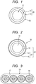
- Fig. 1 is a cross-sectional view of an optical fiber strand 14 according to one embodiment of the present invention.
- Fig. 2 is a cross-sectional view of a colored coated optical fiber 16 according to one embodiment of the present invention.
- Fig. 3 is a cross-sectional view of an optical fiber ribbon 18 according to one embodiment of the present invention.
- the optical fiber strand 14 includes a glass optical fiber 11 and a coating layer 20 covering the glass optical fiber 11.
- the coating layer 20 includes: a primary layer (hereinafter, may also be referred to as "primary coating layer”) 12 covering the glass optical fiber 11; and a secondary layer (hereinafter, may also be referred to as "secondary coating layer”) 13 covering the primary coating layer 12.
- the primary coating layer 12 is a soft resin and accordingly has a relatively low Young's modulus.
- the secondary coating layer 13 is a hard resin and accordingly has a higher Young's modulus than that of the primary coating layer 12. Note that since the secondary coating layer 13 is formed on the primary coating layer 12, the coating layer 20 can be said as a laminate in which the primary coating layer 12 and the secondary coating layer 13 are laminated in this order in a cylindrical form.
- the colored coated optical fiber 16 includes the glass optical fiber 11 and a coating layer 22 covering the glass optical fiber 11.
- the coating layer 22 includes the primary coating layer 12, the secondary coating layer 13, and a colored layer 15 covering the secondary coating layer 13.
- the colored coated optical fiber 16 has a structure in which the optical fiber strand 14 is coated with the colored layer 15.
- the coating layer 22 can be said as a laminate in which the primary coating layer 12, the secondary coating layer 13, and the colored layer 15 are laminated in this order in a cylindrical form.
- reference numeral 21 denotes a laminate of the secondary coating layer 13 and the colored layer 15 formed to cover the secondary coating layer 13.
- the optical fiber ribbon 18 includes multiples of the colored coated optical fibers 16 arranged on a plane, and a ribbon resin 17 covering the multiples of the colored coated optical fibers 16 arranged on the plane.
- a coating resin used as the raw material for the primary coating layer 12 and the secondary coating layer 13 of the optical fiber strand 14 as well as a UV curing resin used as a colored resin serving as the raw material for the colored layer 15 of the colored coated optical fiber 16 mainly contains, for example, an oligomer, a diluted monomer, a photoinitiator, a silane coupling agent, a sensitizer, a pigment, and various additives.
- the oligomer polyether urethane acrylate, epoxy acrylate, polyester acrylate, silicone acrylate, or the like is mainly used.
- the diluted monomer a monofunctional monomer or a multifunctional monomer is used.
- One characteristic of the present invention is that in the colored coated optical fiber 16 having the colored layer 15 on the circumference of the optical fiber strand 14 including the glass optical fiber 11, the primary coating layer 12 formed on the glass optical fiber 11, and the secondary coating layer 13, a ratio of a thermal expansion coefficient of the laminate 21 including the secondary coating layer 13 and the colored layer 15 to that of the secondary coating layer 13 is from 0.98 to 1.03 both inclusive.
- a ratio of a glass transition temperature Tg based on a dynamic viscoelasticity within a temperature range from -100°C to 150°C of a laminate 21 including the secondary coating layer 13 and the colored layer 15 to that of the secondary coating layer 13 is from 0.96 to 1.03 both inclusive.
- the two characteristics make it possible to suppress internal distortion between the secondary coating layer as the secondary layer and the colored layer when immersed in water.
- the first characteristic makes it possible to expand and contract the secondary coating layer 13 and the colored layer 15 in the same manner when the temperature changes or when the colored coated optical fiber 16 is immersed in hot water, reducing internal distortion between the secondary coating layer 13 and the colored layer 15. Thereby, displacement of the bonding surfaces of the secondary coating layer 13 and the colored layer 15 can be reduced.
- the second characteristic also makes it possible to expand and contract both of the secondary coating layer 13 and the colored layer 15 in the same manner when the temperature changes or when the colored coated optical fiber 16 is immersed in hot water, thereby reducing internal distortion between the secondary coating layer 13 and the colored layer 15.
- it is possible to suppress a force to peel the primary coating layer 12 from the glass optical fiber 11 at the interface between the glass optical fiber 11 and the primary coating layer 12 as the primary layer.
- the water may pass through the colored layer 15 and may intrude into the secondary coating layer 13 and the primary coating layer 12, and as a result, peeling and delamination may occur in some cases at a portion where an adhesive force is weak at the interface between the glass optical fiber 11 and the primary coating layer 12.
- peeling and delamination may occur in some cases at a portion where an adhesive force is weak at the interface between the glass optical fiber 11 and the primary coating layer 12.
- the influence of osmotic pressure is exerted on the delaminated portion in such a manner as to reduce the concentration to take up a lot of water.
- the secondary coating layer 13 with the colored layer 15 in terms of glass transition temperature and thermal expansion coefficient, it is possible to prevent accumulation of water into the colored coated optical fiber 16.
- Patent Literature 1 a primary layer, a secondary layer, and a colored layer are arranged in such a manner that the Young's modulus and the glass transition temperature are increased from the inside to the outside.
- This aims to reduce nonuniform transmission of an internal stress attributable to, for example, distortion of each coating layer, making it possible to suppress peeling at a portion between layers where an adhesive force is weak and formation of a blister.
- the colored layer has a higher Young's modulus than the secondary layer, and that the colored layer has a higher glass transition temperature than the secondary layer, internal distortion is likely to occur at the interface between the secondary layer and the colored layer.
- a colored layer has a high cross-link density
- a secondary layer has a low cross-link density. Accordingly, once water passes through the colored layer and enters the inside, the water having intruded into the inside is intercepted by the colored layer having a high cross-link density, and hardly goes outside from the colored layer. In other words, conventionally, water enters the colored coated optical fiber, and the water thus entered hardly goes outside.
- the secondary coating layer 13 and the colored layer 15 have almost the same glass transition temperature and thermal expansion coefficient. Accordingly, even if water passes through the colored layer 15 and enters the inside of the colored coated optical fiber 16, the water thus entered readily passes through the colored layer 15. In other words, water can go inside and outside the colored layer 15. Accordingly, even if water unexpectedly enters the inside of the colored coated optical fiber 16, the water thus entered is easily discharged to the outside. It is made difficult to exert osmotic pressure in the colored coated optical fiber 16.
- the secondary coating layer 13 and the colored layer 15 expand and contract in the same manner when the temperature changes.
- the secondary coating layer 13 and the colored layer 15 are made to have the same or almost the same thermal expansion coefficient and glass transition temperature.
- the present invention focuses on the secondary coating layer 13 and the laminate 21, and the first and second characteristics are employed as indicators to make the secondary coating layer 13 and colored layer 15 have almost the same thermal expansion coefficient and glass transition temperature.
- the secondary coating layer 13 and the laminate 21 including the secondary coating layer 13 and the colored layer 15 in the present invention suppose the colored layer 15 and the secondary coating layer 13 greatly differ from each other in thermal expansion coefficient and glass transition temperature. In this case, the secondary coating layer 13 and the laminate 21 also greatly differ from each other in thermal expansion coefficient and glass transition temperature. Meanwhile, when the colored layer 15 and the secondary coating layer 13 have almost the same thermal expansion coefficient and glass transition temperature, the secondary coating layer 13 and the laminate 21 should have almost the same thermal expansion coefficient and glass transition temperature. In the present invention, it is important that both of the secondary coating layer 13 and the colored layer 15 expand and contract in the same manner, and that the secondary coating layer 13 and the colored layer 15 have almost the same thermal expansion coefficient and glass transition temperature.
- the thermal expansion coefficients and glass transition temperatures of the secondary coating layer 13 and the laminate 21 are linked to the thermal expansion coefficients and glass transition temperatures of the secondary coating layer 13 and the colored layer 15. Accordingly, in the present invention, whether the secondary coating layer 13 has almost the same thermal expansion coefficient and glass transition temperature as those of the colored layer 15 is indirectly determined using the thermal expansion coefficients and glass transition temperatures of the secondary coating layer 13 and the laminate 21 as the indicators.
- the optical fiber strand 14 was manufactured in which the glass optical fiber 11 made of quartz glass in Fig. 1 was coated with a coating resin layer (coating layer 20) including two layers of the primary coating layer 12 and the secondary coating layer 13.
- a UV curing resin was used as each of the resins.
- the UV curing resin contained an oligomer, a diluted monomer, a photoinitiator, a chain transfer agent, and an additive.
- the colored coated optical fiber 16 as shown in Fig. 2 was obtained.
- the optical fiber 14 was manufactured in which: the glass optical fiber 11 made of quartz glass had an outer diameter of 125 ⁇ m; the primary coating layer 12 had an outer diameter of 183 ⁇ m and 196 ⁇ m; and the secondary coating layer 13 had an outer diameter of 245 ⁇ m. Then, in another step, the optical fiber 14 was coated with the colored layer 15 to obtain the colored coated optical fiber 16 having an outer diameter of 255 ⁇ m.
- the outer diameter of the glass optical fiber 11 is 80 ⁇ m to 125 ⁇ m; the outer diameter of the primary coating layer 12 is 120 ⁇ m to 200 ⁇ m; the outer diameter of the secondary coating layer 13 is 165 ⁇ m to 245 ⁇ m; and the outer diameter of the colored layer 15 (colored coated optical fiber 16) is 135 ⁇ m to 255 ⁇ m.
- four colored coated optical fibers 16 thus obtained were arranged in parallel on a plane as shown in Fig. 3 and collectively coated with the ribbon resin 17 made of a UV curing resin to thus form the optical fiber ribbon 18.
- the adhesive force between the glass optical fiber 11 and the primary coating layer 12 of the optical fiber strand 14 used in the present invention was 5 N to 20 N.
- Pullout force in 48th International Wire and Cable Symposium "Polymer coatings For Optical fibers" was used.
- the speed of 5 mm/min was employed.
- the colored layer 15 can have almost the same thermal expansion coefficient as that of the secondary coating layer 13.
- the degree of cure of the UV curing resin used for the colored layer 15 may be decreased. Nevertheless, this is adjustable by changing the kind of photoinitiator or increasing the amount to be added.
- an alkylphenone-based photopolymerization initiator or acylphosphine oxide-based photopolymerization initiator was added as the photoinitiator of the UV curing resin used for the colored layer.
- a monofunctional monomer such as isobornyl acrylate, the Young's modulus can be increased without increasing the glass transition temperature.
- a method of determining a thermal expansion coefficient will be described.
- a thermal expansion coefficient volumetric expansion coefficient
- two types of coating samples were prepared for each of the secondary coating layer 13 and the laminate 21.
- One is a fiber sample (the optical fiber strand 14 or the colored coated optical fiber 16) in which a glass optical fiber is coated with a coating layer (the coating layer 20 or the coating layer 22).
- the other is a tubular coating sample of only a coating layer (the coating layer 20 or the coating layer 22) obtained by pulling out the glass optical fiber from the fiber sample (the optical fiber strand 14 or the colored coated optical fiber 16).
- the thermal expansion coefficient was measured in a longitudinal direction and in an outer diameter direction using TMA thermomechanical analysis (Mettler Toledo, TMA-40).
- the measuring conditions were: 0 loads added, a temperature range from -100°C to 100°C, and a rate of temperature rise of 10°C/min.
- the measurement in the longitudinal direction was performed using the tubular coating sample by a tensile mode.
- the measurement in the outer diameter direction was performed using the fiber sample by a compressive mode under a condition where the fiber sample included the glass optical fiber. Since the linear expansion coefficient of the coating layer varies considerably at around the glass transition point of the coating layer, it is preferable to set the temperature range for the measurement within a range including all of the glass transition points of the coating layer.
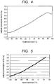
- Fig. 4 shows a relation between the temperature and the linear expansion ratio in the longitudinal direction thus measured.
- Fig. 5 shows a relation between the temperature and the linear expansion ratio in the outer diameter direction.
- Each linear expansion coefficient was determined from the range where the measurement results changed linearly, that is, from the slope of the temperature range from -50 to 25°C.
- the primary coating layer 12 has a low glass transition temperature of approximately -50°C. In the temperature range from and above the glass transition temperature, the primary coating layer 12 (primary layer) of the tubular coating sample has a Young's modulus significantly lower than those of the secondary coating layer 13 (secondary layer) and the colored layer 15. Accordingly, the secondary coating layer 13 in the coating layer 20 and the secondary coating layer 13 and the colored layer 15 in the coating layer 22 can freely expand and contract.
- the volumetric expansion coefficient of the coating layer 20 is almost the same as the volumetric expansion coefficient of the secondary coating layer 13.
- the volumetric expansion coefficient of the coating layer 22 is almost the same as the volumetric expansion coefficient of the laminate 21 including the secondary coating layer 13 and the colored layer 15.
- volumetric thermal expansion coefficients can be determined from the respective linear expansion coefficients of the secondary coating layer 13 and the laminate 21 using Formula 1).
- ⁇ s ⁇ SL + 2 ⁇ ⁇ SR
- volumetric expansion coefficients thus calculated, in Table 1, the volumetric expansion coefficient of the secondary coating layer 13 for each Example is recorded in the column of “volumetric expansion coefficient of secondary coating layer,” and the volumetric expansion coefficient of the laminate 21 is recorded in the column of "volumetric expansion coefficient of laminate.”
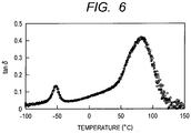
- a method of determining a glass transition temperature Tg will be described.
- DMA dynamic mechanical analysis (TA Instruments, RSA3) was used to measure the glass transition temperatures Tg of the secondary coating layer 13 and the laminate 21.
- the glass transition temperature was defined as a temperature at which the maximum value of tan ⁇ appeared as shown in Fig. 6 .
- the measurement was performed using the tubular coating sample by a tensile test under conditions of a mark distance of 20 mm, a frequency of 1 Hz, and a rate of temperature rise of 2°C/min. Note that when the tubular coating sample is measured within the temperature range from -100°C to 150°C, two tan ⁇ peaks appears on a low-temperature side and a high-temperature side. One on the low-temperature side represents the glass transition temperature of the primary coating layer 12 (primary layer), while one on the high-temperature side represents the glass transition temperature of the secondary coating layer 13 or the colored layer 15.
- the glass transition temperature of the secondary coating layer 13 for each Example is recorded in the column of "glass transition temperature of secondary coating layer”
- the glass transition temperature of the laminate 21 is recorded in the column of "glass transition temperature of laminate.”
- An optical fiber strand or a colored coated optical fiber having a length of approximately 1 km was obtained using the manufactured optical fiber strand 14 and colored coated optical fiber 16, and was immersed in 60°C hot water.
- the transmission loss after the immersion was measured.
- the transmission loss was measured using an optical pulse tester MW9076B manufactured by Anritsu Corporation, by measuring the transmission loss of a wavelength of 1.55 ⁇ m in a longitudinal direction on the basis of backward scattering loss coefficient of light (OTDR). Then, the water temperature was increased to 60°C, and the immersion was continued for 90 days. After that, when the transmission loss was recognized as being increased by 0.1 dB/km or more, the resistance to the operating environment was determined to be insufficient, and marked by ⁇ in Table 1.
- the colored coated optical fiber of the present invention is a colored coated optical fiber in which an optical fiber strand including a glass optical fiber coated with two coating layers including a primary coating layer as a primary layer and a secondary coating layer as a secondary layer is further coated with a coating layer made of a colored resin.
- the ratio of the thermal expansion coefficient of the laminate 21 (the secondary coating layer 13 + the colored layer 15) to that of the secondary coating layer 13 is 0.98 or more and 1.03 or less.
- the ratio of the glass transition temperature Tg based on a dynamic viscoelasticity within the temperature range from -100°C to 150°C of the laminate 21 (secondary coating layer 13 + colored layer 15) to that of the secondary coating layer 13 is 0.96 or more and 1.03 or less.
- the laminate 21 (the secondary coating layer 13 + the colored layer 15) and the secondary coating layer 13 desirably have equal or approximately equal thermal expansion coefficient and glass transition temperature.
Description
- The present invention relates to a colored coated optical fiber accommodated in an optical fiber cable. Specifically, the present invention relates to a colored coated optical fiber which suppresses an increase in transmission loss of an optical fiber due to an operating environment and aged deterioration. Particularly, the present invention relates to a colored coated optical fiber which hardly has an increase in transmission loss even when immersed in water for an extended period of time.
- In a drawing process of quartz glass for manufacturing an optical fiber, a coating resin is immediately applied to the circumference of an optical fiber to prevent reduction in strength of the optical fiber. For the identification, a colored layer is provided. A UV curing resin is mainly used as the coating resin for an optical fiber. A urethane acrylate or epoxy acrylate is used as the UV curing resin.
- In an optical fiber, transmission losses are increased by various external stresses and microbending caused thereby. For this reason, to protect the optical fiber from such external stresses, an optical fiber strand is generally provided with a coating having a two-layer structure including a soft layer and a hard layer. A soft resin having a relatively low Young's modulus is used for the inner layer, which is into contact with quartz glass, as a buffer layer (hereinafter, primary layer), while a hard resin having a relatively high Young's modulus is used for the outer layer as a protective layer (hereinafter, secondary layer). Generally, a resin having a Young's modulus of 3 MPa or less is used for the primary layer, and a resin having a Young's modulus of 500 MPa or more is used for the secondary layer.
- In a method of manufacturing an optical fiber, a preform mainly containing quartz glass is melted by heating in a drawing furnace, and a quartz glass optical fiber is drawn from the preform. Then, a liquid UV curing resin is applied to the quartz glass optical fiber using a coating die. Subsequently, the resultant is irradiated with UV rays to cure the UV curing resin. By such a method, the optical fiber is coated with the primary layer and the secondary layer, and thereby an optical fiber strand is manufactured. Furthermore, in the subsequent step, the circumference of the optical fiber strand thus obtained is coated with a coating layer made of a colored resin. Hence, a colored coated optical fiber is manufactured.
- In this description, such a glass optical fiber coated with a primary layer and a secondary layer is referred to as an optical fiber strand; an optical fiber strand whose circumference is further coated with a coating layer made of a colored resin is referred to as a colored coated optical fiber; furthermore, multiple colored coated optical fibers arranged on a plane and collectively coated with a ribbon resin are referred to as an optical fiber ribbon.
- Meanwhile, in order to manufacture a highly reliable colored coated optical fiber which prevents an increase in transmission loss even when used under an immersed condition in 60°C hot water, Patent Literature 1 proposes to increase the Young's modulus of a colored layer higher than the Young's modulus of a secondary layer, and to increase the glass transition temperature of the colored layer higher than the glass transition temperature of the secondary layer.
- In Patent Literature 3 a fiber optic coating having improved toughness is disclosed. This document also provides a method of improving the tensile, elongation, and/or modulus (overall toughness) of a radiation curable composition by reacting in a free multi-functional isocyanate prior to curing.
- Patent Literature 4 discloses an optical fiber strand for a fiber grating with a primary covering layer and a secondary covering layer on a glass optical fiber bare wire, and the primary covering layer is constituted of a resin composition that incorporates silane coupling agent by 0.05-5 mass % and whose contactness with glass is set 5-20 N/m.
-
- PTL 1:
Japanese Patent Application Laid-Open No. 2002-255590 - PTL 2:
Japanese Patent No. 2925099 - PTL 3:
WO/02 055447 A2 - PTL 4:
JP 2004 004423 A - With recent remarkable spread of optical fibers, the applicable range of optical fiber cables is expanding. The long-term reliability required for optical fiber cables is becoming very stringent. For this reason, demanded is a colored coated optical fiber which is more and more unlikely to have an increase in transmission loss even when used under an immersed condition in water.
- However, there is a limit to handling the above-described problems while achieving a balance in adhesive force at the interface between layers. Even when the colored coated optical fiber described in Patent Literature 1 is used, the long-term reliability thereof is insufficient.
- An object of the present invention is to provide a colored coated optical fiber which hardly has an increase in transmission loss even when immersed in water.
- In order to achieve such an object, a colored coated optical fiber according to claim 1 of the present invention is provided.
- Specifically, the colored coated optical fiber includes: a glass optical fiber; a primary coating layer covering the glass optical fiber; a secondary coating layer covering the primary coating layer; and a colored layer covering the secondary coating layer. A ratio of a thermal expansion coefficient of a laminate including the secondary coating layer and the colored layer covering the secondary coating layer to that of the secondary coating layer is 0.98 or more and 1.03 or less. A ratio of a glass transition temperature based on a dynamic viscoelasticity within a temperature range from -100°C to 150°C of the laminate to that of the secondary coating layer is 0.96 or more and 1.03 or less.
- The present invention makes it possible to provide a colored coated optical fiber which hardly has an increase in transmission loss even when used under an immersed condition in water.
-
-
Fig. 1 is a cross-sectional view of an optical fiber strand according to one embodiment of the present invention. -
Fig. 2 is a cross-sectional view of a colored coated optical fiber according to one embodiment of the present invention. -
Fig. 3 is a cross-sectional view of an optical fiber ribbon according to one embodiment of the present invention. -
Fig. 4 is a graph for illustrating the temperature dependence of the linear expansion ratio of a tubular coating sample according to one embodiment of the present invention. -
Fig. 5 is a graph for illustrating the temperature dependence of the linear expansion ratio of a fiber sample according to one embodiment of the present invention. -
Fig. 6 is a graph for explaining how to determine a glass transition temperature according to one embodiment of the present invention. - Hereinafter, embodiments of the present invention will be described in detail with reference to the drawings. Note that, in the drawings to be described below, the same reference numerals denote elements having the same function, and repetitive description will be omitted.
- As a result of earnest study on the cause of an increase in transmission loss of a coated optical fiber exposed to a water-immersed condition, it has been discovered that peeling at the interface between a glass optical fiber and a primary layer, that is, delamination is observed in a coated optical fiber whose transmission loss has been increased. Further, it has been discovered that peeling is observed also at the interface between a secondary layer and a colored layer or interface between the colored layer and a ribbon layer.
- Delamination occurs when a force to peel the coating layer at the interface between the glass optical fiber and the coating layer exceeds an adhesive force at the interface between the glass optical fiber and the coating layer. Moreover, when a nonuniform force is applied to the glass optical fiber, transmission loss occurs.
- As an embodiment for carrying out the present invention, an optical fiber strand is manufactured in which a glass optical fiber is coated with a primary layer and a secondary layer. The optical fiber strand is coated with a colored layer to manufacture a colored coated optical fiber. As a resin used for the coating layers, a UV curing resin is used. Further, multiples of the colored coated optical fibers are arranged in parallel on a plane and collectively coated with a ribbon resin made of a UV curing resin, and it is thereby possible to form an optical fiber ribbon.
-
Fig. 1 is a cross-sectional view of anoptical fiber strand 14 according to one embodiment of the present invention.Fig. 2 is a cross-sectional view of a colored coatedoptical fiber 16 according to one embodiment of the present invention.Fig. 3 is a cross-sectional view of anoptical fiber ribbon 18 according to one embodiment of the present invention. - In
Fig. 1 , theoptical fiber strand 14 includes a glassoptical fiber 11 and acoating layer 20 covering the glassoptical fiber 11. Thecoating layer 20 includes: a primary layer (hereinafter, may also be referred to as "primary coating layer") 12 covering the glassoptical fiber 11; and a secondary layer (hereinafter, may also be referred to as "secondary coating layer") 13 covering theprimary coating layer 12. Theprimary coating layer 12 is a soft resin and accordingly has a relatively low Young's modulus. Meanwhile, thesecondary coating layer 13 is a hard resin and accordingly has a higher Young's modulus than that of theprimary coating layer 12. Note that since thesecondary coating layer 13 is formed on theprimary coating layer 12, thecoating layer 20 can be said as a laminate in which theprimary coating layer 12 and thesecondary coating layer 13 are laminated in this order in a cylindrical form. - Moreover, in
Fig. 2 , the colored coatedoptical fiber 16 includes the glassoptical fiber 11 and acoating layer 22 covering the glassoptical fiber 11. Thecoating layer 22 includes theprimary coating layer 12, thesecondary coating layer 13, and acolored layer 15 covering thesecondary coating layer 13. In other words, the colored coatedoptical fiber 16 has a structure in which theoptical fiber strand 14 is coated with thecolored layer 15. Note that since thesecondary coating layer 13 is formed on theprimary coating layer 12 and thecolored layer 15 is further formed on thesecondary coating layer 13, thecoating layer 22 can be said as a laminate in which theprimary coating layer 12, thesecondary coating layer 13, and thecolored layer 15 are laminated in this order in a cylindrical form. Further, inFig. 2 ,reference numeral 21 denotes a laminate of thesecondary coating layer 13 and thecolored layer 15 formed to cover thesecondary coating layer 13. - Furthermore, in
Fig. 3 , theoptical fiber ribbon 18 includes multiples of the colored coatedoptical fibers 16 arranged on a plane, and aribbon resin 17 covering the multiples of the colored coatedoptical fibers 16 arranged on the plane. - Note that a coating resin used as the raw material for the
primary coating layer 12 and thesecondary coating layer 13 of theoptical fiber strand 14 as well as a UV curing resin used as a colored resin serving as the raw material for thecolored layer 15 of the colored coatedoptical fiber 16 mainly contains, for example, an oligomer, a diluted monomer, a photoinitiator, a silane coupling agent, a sensitizer, a pigment, and various additives. As the oligomer, polyether urethane acrylate, epoxy acrylate, polyester acrylate, silicone acrylate, or the like is mainly used. As the diluted monomer, a monofunctional monomer or a multifunctional monomer is used. - One characteristic of the present invention is that in the colored coated
optical fiber 16 having the coloredlayer 15 on the circumference of theoptical fiber strand 14 including the glassoptical fiber 11, theprimary coating layer 12 formed on the glassoptical fiber 11, and thesecondary coating layer 13, a ratio of a thermal expansion coefficient of the laminate 21 including thesecondary coating layer 13 and thecolored layer 15 to that of thesecondary coating layer 13 is from 0.98 to 1.03 both inclusive. - In addition, another characteristic of the present invention is that a ratio of a glass transition temperature Tg based on a dynamic viscoelasticity within a temperature range from -100°C to 150°C of a laminate 21 including the
secondary coating layer 13 and thecolored layer 15 to that of thesecondary coating layer 13 is from 0.96 to 1.03 both inclusive. - In the present invention, the two characteristics make it possible to suppress internal distortion between the secondary coating layer as the secondary layer and the colored layer when immersed in water.
- Specifically, according to the colored coated optical fiber of the present invention, the first characteristic makes it possible to expand and contract the
secondary coating layer 13 and thecolored layer 15 in the same manner when the temperature changes or when the colored coatedoptical fiber 16 is immersed in hot water, reducing internal distortion between thesecondary coating layer 13 and thecolored layer 15. Thereby, displacement of the bonding surfaces of thesecondary coating layer 13 and thecolored layer 15 can be reduced. Thus, it is possible to reduce damage at the interface between the glassoptical fiber 11 and the coating resin, such as the interface between the glassoptical fiber 11 and theprimary coating layer 12, which contributes to an increase in transmission loss, and to suppress delamination which causes the loss increase. - In addition, the second characteristic also makes it possible to expand and contract both of the
secondary coating layer 13 and thecolored layer 15 in the same manner when the temperature changes or when the colored coatedoptical fiber 16 is immersed in hot water, thereby reducing internal distortion between thesecondary coating layer 13 and thecolored layer 15. Thus, it is possible to suppress a force to peel theprimary coating layer 12 from the glassoptical fiber 11 at the interface between the glassoptical fiber 11 and theprimary coating layer 12 as the primary layer. - Meanwhile, when the colored coated
optical fiber 16 is immersed in water, the water may pass through thecolored layer 15 and may intrude into thesecondary coating layer 13 and theprimary coating layer 12, and as a result, peeling and delamination may occur in some cases at a portion where an adhesive force is weak at the interface between the glassoptical fiber 11 and theprimary coating layer 12. In this manner, once delamination occurs, the influence of osmotic pressure is exerted on the delaminated portion in such a manner as to reduce the concentration to take up a lot of water. However, by matching thesecondary coating layer 13 with thecolored layer 15 in terms of glass transition temperature and thermal expansion coefficient, it is possible to prevent accumulation of water into the colored coatedoptical fiber 16. - For example, in Patent Literature 1, a primary layer, a secondary layer, and a colored layer are arranged in such a manner that the Young's modulus and the glass transition temperature are increased from the inside to the outside. This aims to reduce nonuniform transmission of an internal stress attributable to, for example, distortion of each coating layer, making it possible to suppress peeling at a portion between layers where an adhesive force is weak and formation of a blister. Nevertheless, with such an arrangement that the colored layer has a higher Young's modulus than the secondary layer, and that the colored layer has a higher glass transition temperature than the secondary layer, internal distortion is likely to occur at the interface between the secondary layer and the colored layer.
- In addition, there is a tendency that: the higher the Young's modulus, the lower the thermal expansion coefficient. Hence, when the colored coated optical fiber disclosed in Patent Literature 1 is immersed in hot water, internal distortion may occur at the interface between the secondary layer and the colored layer. The internal distortion causes peeling and delamination in some cases at a portion where an adhesive force is weak at the interface between the glass optical fiber and the primary layer. Once an eluted component is accumulated at the delaminated portion, osmotic pressure is exerted in such a manner as to reduce the concentration to take up a lot of water as described in Patent Literature 2. However, it can be inferred that in the colored coated optical fiber disclosed in Patent Literature 1, the presence of the colored layer having a high Young's modulus creates a condition where water accumulated into the colored coated optical fiber cannot go outside the colored coated optical fiber.
- Conventionally, a colored layer has a high cross-link density, while a secondary layer has a low cross-link density. Accordingly, once water passes through the colored layer and enters the inside, the water having intruded into the inside is intercepted by the colored layer having a high cross-link density, and hardly goes outside from the colored layer. In other words, conventionally, water enters the colored coated optical fiber, and the water thus entered hardly goes outside. In contrast, in the present invention, the
secondary coating layer 13 and thecolored layer 15 have almost the same glass transition temperature and thermal expansion coefficient. Accordingly, even if water passes through thecolored layer 15 and enters the inside of the colored coatedoptical fiber 16, the water thus entered readily passes through thecolored layer 15. In other words, water can go inside and outside thecolored layer 15. Accordingly, even if water unexpectedly enters the inside of the colored coatedoptical fiber 16, the water thus entered is easily discharged to the outside. It is made difficult to exert osmotic pressure in the colored coatedoptical fiber 16. - As described above, in the present invention, it is important that the
secondary coating layer 13 and thecolored layer 15 expand and contract in the same manner when the temperature changes. For this purpose, thesecondary coating layer 13 and thecolored layer 15 are made to have the same or almost the same thermal expansion coefficient and glass transition temperature. To achieve this, the present invention focuses on thesecondary coating layer 13 and the laminate 21, and the first and second characteristics are employed as indicators to make thesecondary coating layer 13 andcolored layer 15 have almost the same thermal expansion coefficient and glass transition temperature. - Between the
secondary coating layer 13 and the laminate 21 including thesecondary coating layer 13 and thecolored layer 15 in the present invention, suppose thecolored layer 15 and thesecondary coating layer 13 greatly differ from each other in thermal expansion coefficient and glass transition temperature. In this case, thesecondary coating layer 13 and the laminate 21 also greatly differ from each other in thermal expansion coefficient and glass transition temperature. Meanwhile, when thecolored layer 15 and thesecondary coating layer 13 have almost the same thermal expansion coefficient and glass transition temperature, thesecondary coating layer 13 and the laminate 21 should have almost the same thermal expansion coefficient and glass transition temperature. In the present invention, it is important that both of thesecondary coating layer 13 and thecolored layer 15 expand and contract in the same manner, and that thesecondary coating layer 13 and thecolored layer 15 have almost the same thermal expansion coefficient and glass transition temperature. As described above, the thermal expansion coefficients and glass transition temperatures of thesecondary coating layer 13 and the laminate 21 are linked to the thermal expansion coefficients and glass transition temperatures of thesecondary coating layer 13 and thecolored layer 15. Accordingly, in the present invention, whether thesecondary coating layer 13 has almost the same thermal expansion coefficient and glass transition temperature as those of thecolored layer 15 is indirectly determined using the thermal expansion coefficients and glass transition temperatures of thesecondary coating layer 13 and the laminate 21 as the indicators. - As the present examples, the
optical fiber strand 14 was manufactured in which the glassoptical fiber 11 made of quartz glass inFig. 1 was coated with a coating resin layer (coating layer 20) including two layers of theprimary coating layer 12 and thesecondary coating layer 13. As each of the resins, a UV curing resin was used. The UV curing resin contained an oligomer, a diluted monomer, a photoinitiator, a chain transfer agent, and an additive. By changing constituent materials, severaloptical fiber strands 14 were obtained. Moreover, the colored coatedoptical fiber 16 as shown inFig. 2 was obtained. Specifically, theoptical fiber 14 was manufactured in which: the glassoptical fiber 11 made of quartz glass had an outer diameter of 125 µm; theprimary coating layer 12 had an outer diameter of 183 µm and 196 µm; and thesecondary coating layer 13 had an outer diameter of 245 µm. Then, in another step, theoptical fiber 14 was coated with thecolored layer 15 to obtain the colored coatedoptical fiber 16 having an outer diameter of 255 µm. Note that in order to retain the properties as theoptical fiber strand 14, the following dimensions are normally employed: the outer diameter of the glassoptical fiber 11 is 80 µm to 125 µm; the outer diameter of theprimary coating layer 12 is 120 µm to 200 µm; the outer diameter of thesecondary coating layer 13 is 165 µm to 245 µm; and the outer diameter of the colored layer 15 (colored coated optical fiber 16) is 135 µm to 255 µm. Further, four colored coatedoptical fibers 16 thus obtained were arranged in parallel on a plane as shown inFig. 3 and collectively coated with theribbon resin 17 made of a UV curing resin to thus form theoptical fiber ribbon 18. - Note that the adhesive force between the glass
optical fiber 11 and theprimary coating layer 12 of theoptical fiber strand 14 used in the present invention was 5 N to 20 N. Here, in the method of measuring the adhesive force, Pullout force in 48th International Wire and Cable Symposium "Polymer coatings For Optical fibers" was used. The speed of 5 mm/min was employed. - If formed with a composition equivalent to that of the coating resin used for the
secondary coating layer 13, thecolored layer 15 can have almost the same thermal expansion coefficient as that of thesecondary coating layer 13. In this case, it is concerned that the degree of cure of the UV curing resin used for thecolored layer 15 may be decreased. Nevertheless, this is adjustable by changing the kind of photoinitiator or increasing the amount to be added. In the present examples, an alkylphenone-based photopolymerization initiator or acylphosphine oxide-based photopolymerization initiator was added as the photoinitiator of the UV curing resin used for the colored layer. In addition, by using a monofunctional monomer such as isobornyl acrylate, the Young's modulus can be increased without increasing the glass transition temperature. - A method of determining a thermal expansion coefficient (volumetric expansion coefficient) will be described. To measure the thermal expansion coefficients of the
secondary coating layer 13 of theoptical fiber strand 14 and thelaminate 21 of the colored coatedoptical fiber 16, two types of coating samples were prepared for each of thesecondary coating layer 13 and the laminate 21. One is a fiber sample (theoptical fiber strand 14 or the colored coated optical fiber 16) in which a glass optical fiber is coated with a coating layer (thecoating layer 20 or the coating layer 22). Meanwhile, the other is a tubular coating sample of only a coating layer (thecoating layer 20 or the coating layer 22) obtained by pulling out the glass optical fiber from the fiber sample (theoptical fiber strand 14 or the colored coated optical fiber 16). The thermal expansion coefficient was measured in a longitudinal direction and in an outer diameter direction using TMA thermomechanical analysis (Mettler Toledo, TMA-40). The measuring conditions were: 0 loads added, a temperature range from -100°C to 100°C, and a rate of temperature rise of 10°C/min. The measurement in the longitudinal direction was performed using the tubular coating sample by a tensile mode. The measurement in the outer diameter direction was performed using the fiber sample by a compressive mode under a condition where the fiber sample included the glass optical fiber. Since the linear expansion coefficient of the coating layer varies considerably at around the glass transition point of the coating layer, it is preferable to set the temperature range for the measurement within a range including all of the glass transition points of the coating layer. -
Fig. 4 shows a relation between the temperature and the linear expansion ratio in the longitudinal direction thus measured.Fig. 5 shows a relation between the temperature and the linear expansion ratio in the outer diameter direction. Each linear expansion coefficient was determined from the range where the measurement results changed linearly, that is, from the slope of the temperature range from -50 to 25°C. - Normally, the primary coating layer 12 (primary layer) has a low glass transition temperature of approximately -50°C. In the temperature range from and above the glass transition temperature, the primary coating layer 12 (primary layer) of the tubular coating sample has a Young's modulus significantly lower than those of the secondary coating layer 13 (secondary layer) and the
colored layer 15. Accordingly, thesecondary coating layer 13 in thecoating layer 20 and thesecondary coating layer 13 and thecolored layer 15 in thecoating layer 22 can freely expand and contract. - In other words, it can be said that the volumetric expansion coefficient of the
coating layer 20 is almost the same as the volumetric expansion coefficient of thesecondary coating layer 13. In addition, it can be said that the volumetric expansion coefficient of thecoating layer 22 is almost the same as the volumetric expansion coefficient of the laminate 21 including thesecondary coating layer 13 and thecolored layer 15. - Thus, the volumetric thermal expansion coefficients can be determined from the respective linear expansion coefficients of the
secondary coating layer 13 and the laminate 21 using Formula 1).
- βs: the volumetric expansion coefficient of the
secondary coating layer 13 or the laminate 21 - αSL: the linear expansion coefficient in the longitudinal direction of the
secondary coating layer 13 or the laminate 21 - αSR: the linear expansion coefficient in the outer diameter direction of the
secondary coating layer 13 or the laminate 21 - As to the volumetric expansion coefficients thus calculated, in Table 1, the volumetric expansion coefficient of the
secondary coating layer 13 for each Example is recorded in the column of "volumetric expansion coefficient of secondary coating layer," and the volumetric expansion coefficient of the laminate 21 is recorded in the column of "volumetric expansion coefficient of laminate." - A method of determining a glass transition temperature Tg will be described. DMA dynamic mechanical analysis (TA Instruments, RSA3) was used to measure the glass transition temperatures Tg of the
secondary coating layer 13 and the laminate 21. The glass transition temperature was defined as a temperature at which the maximum value of tanδ appeared as shown inFig. 6 . The measurement was performed using the tubular coating sample by a tensile test under conditions of a mark distance of 20 mm, a frequency of 1 Hz, and a rate of temperature rise of 2°C/min. Note that when the tubular coating sample is measured within the temperature range from -100°C to 150°C, two tanδ peaks appears on a low-temperature side and a high-temperature side. One on the low-temperature side represents the glass transition temperature of the primary coating layer 12 (primary layer), while one on the high-temperature side represents the glass transition temperature of thesecondary coating layer 13 or thecolored layer 15. - As to the glass transition temperatures thus obtained, in Table 1, the glass transition temperature of the
secondary coating layer 13 for each Example is recorded in the column of "glass transition temperature of secondary coating layer," and the glass transition temperature of the laminate 21 is recorded in the column of "glass transition temperature of laminate." - An optical fiber strand or a colored coated optical fiber having a length of approximately 1 km was obtained using the manufactured
optical fiber strand 14 and colored coatedoptical fiber 16, and was immersed in 60°C hot water. The transmission loss after the immersion was measured. The transmission loss was measured using an optical pulse tester MW9076B manufactured by Anritsu Corporation, by measuring the transmission loss of a wavelength of 1.55 µm in a longitudinal direction on the basis of backward scattering loss coefficient of light (OTDR). Then, the water temperature was increased to 60°C, and the immersion was continued for 90 days. After that, when the transmission loss was recognized as being increased by 0.1 dB/km or more, the resistance to the operating environment was determined to be insufficient, and marked by × in Table 1.[Table 1] Example 1 Example 2 Example 3 Example 4 Example 5 Example 6 Example 7 Example 8 Comparative Example 1 Comparative Example 2 Comparative Example 3 Young's modulus of primary coating layer (MPa) 0.8 0.8 0.7 0.7 0.6 0.6 0.7 0.8 0.6 0.8 0.7 Young's modulus of secondary coating layer (MPa) 900 900 710 710 600 600 710 900 600 900 710 Young's modulus of laminate (secondary coating layer + colored layer) (MPa) 930 900 710 740 730 700 810 700 880 1400 1300 Outer diameter of primary coating layer (pm) 195 195 196 196 183 183 196 195 183 195 196 Volumetric expansion coefficient of secondary coating layer (× 10-4 K-1) 2.72 2.72 2.68 2.68 2.52 2.52 2.68 2.72 2.52 2.72 2.68 Volumetric expansion coefficient of laminate (× 10-4 K-1) 2.68 2.70 2.72 2.75 2.52 2.47 2.61 2.60 2.43 2.39 2.80 Laminate/secondary coating layer (volumetric expansion coefficient) 0.99 0.99 1.01 1.03 1.00 0.98 0.97 0.96 0.96 0.88 1.04 Glass transition temperature of secondary coating layer (°C) 85 85 82 82 75 75 82 85 75 85 82 Glass transition temperature of laminate (°C) 85 86 84 80 77 72 86 81 82 93 95 Laminate/secondary coating layer (glass transition temperature) 1.00 1.01 1.02 0.98 1.03 0.96 1.05 0.95 1.09 1.09 1.16 Transmission loss increase in 60°C water 30days at 1550 nm (dB/km), 0.00 0.00 0.00 0.00 0.00 0.00 0.02 0.00 0.07 0.15 0.24 Transmission loss increase in 60°C water 90days at 1550 nm (dB/km), 0.00 0.00 0.00 0.00 0.00 0.00 0.09 0.05 0.15 0.31 0.55 Determination ○ ○ ○ ○ ○ ○ Δ Δ × × × - As is clear from the above description, the colored coated optical fiber of the present invention is a colored coated optical fiber in which an optical fiber strand including a glass optical fiber coated with two coating layers including a primary coating layer as a primary layer and a secondary coating layer as a secondary layer is further coated with a coating layer made of a colored resin. The ratio of the thermal expansion coefficient of the laminate 21 (the
secondary coating layer 13 + the colored layer 15) to that of thesecondary coating layer 13 is 0.98 or more and 1.03 or less. The ratio of the glass transition temperature Tg based on a dynamic viscoelasticity within the temperature range from -100°C to 150°C of the laminate 21 (secondary coating layer 13 + colored layer 15) to that of thesecondary coating layer 13 is 0.96 or more and 1.03 or less. Hence, as shown in Table 1, in the present examples, the following effects were obtained that: even when the colored coated optical fiber is immersed in 60°C hot water for 30 days, the transmission loss is not increased; furthermore, even when the colored coated optical fiber is immersed in 60°C hot water for 90 days, the transmission loss is not increased. - From the above results, in a case where a secondary coating layer and a colored layer differ from each other in thermal expansion, when the temperature changes, distortion occurs at the interface between the secondary coating layer and the colored layer. When a nonuniform force is generated to the coating layer, the nonuniform force is applied to a glass optical fiber and a primary coating layer, causing peeling at an interface therebetween as well as the loss increase. Against this, the laminate 21 (the
secondary coating layer 13 + the colored layer 15) and thesecondary coating layer 13 desirably have equal or approximately equal thermal expansion coefficient and glass transition temperature.
Claims (2)
- A colored coated optical fiber comprising:a glass optical fiber (11),a primary coating layer (12) covering the glass optical fiber;a secondary coating layer (13) covering the primary coating layer; anda colored layer (15) covering the secondary coating layer (13), wherein a ratio of a thermal expansion coefficient of a laminate including the secondary coating layer (13) and the colored layer (15) covering the secondary coating layer (13) to that of the secondary coating layer (13) is 0.98 or more and 1.03 or less,a ratio of a glass transition temperature based on a dynamic viscoelasticity within a temperature range from -100°C to 150°C of the laminate to that of the secondary coating layer (13) is 0.96 or more and 1.03 or less, characterized in that a photoinitiator added to the second coating layer (13) and a photoinitiator added to the colored layer (15) are of different kind and/or differ in the amounts to be added.
- An optical fiber ribbon (18) characterized by comprising a plurality of the colored coated optical fibers (16) according to claim 1 arranged and collected using a ribbon resin.
Applications Claiming Priority (2)
| Application Number | Priority Date | Filing Date | Title |
|---|---|---|---|
| JP2010261209A JP5041450B2 (en) | 2010-11-24 | 2010-11-24 | Optical fiber colored core |
| PCT/JP2011/005453 WO2012070177A1 (en) | 2010-11-24 | 2011-09-28 | Pigmented fiber optic cable core |
Publications (3)
| Publication Number | Publication Date |
|---|---|
| EP2645143A1 EP2645143A1 (en) | 2013-10-02 |
| EP2645143A4 EP2645143A4 (en) | 2014-04-30 |
| EP2645143B1 true EP2645143B1 (en) | 2017-09-06 |
Family
ID=46145551
Family Applications (1)
| Application Number | Title | Priority Date | Filing Date |
|---|---|---|---|
| EP11843901.7A Active EP2645143B1 (en) | 2010-11-24 | 2011-09-28 | Pigmented fiber optic cable core |
Country Status (6)
| Country | Link |
|---|---|
| US (1) | US8639077B2 (en) |
| EP (1) | EP2645143B1 (en) |
| JP (1) | JP5041450B2 (en) |
| CN (1) | CN103229083B (en) |
| BR (1) | BR112013012253B1 (en) |
| WO (1) | WO2012070177A1 (en) |
Families Citing this family (11)
| Publication number | Priority date | Publication date | Assignee | Title |
|---|---|---|---|---|
| JP5255690B2 (en) | 2011-12-27 | 2013-08-07 | 古河電気工業株式会社 | Optical fiber colored core, optical fiber tape, and optical fiber cable |
| JP5465741B2 (en) | 2012-02-17 | 2014-04-09 | 古河電気工業株式会社 | Optical fiber core, optical fiber tape core and optical cable |
| WO2014185978A1 (en) * | 2013-05-14 | 2014-11-20 | Adc Telecommunications, Inc. | Power/fiber hybrid cable |
| JP2015176015A (en) * | 2014-03-17 | 2015-10-05 | 住友電気工業株式会社 | Optical fiber coloring core wire |
| CN109643000A (en) | 2016-09-30 | 2019-04-16 | 株式会社藤仓 | The manufacturing method of optical fiber coloring core wire, fiber optic cables and optical fiber coloring core wire |
| CN109716195A (en) * | 2016-09-30 | 2019-05-03 | 株式会社藤仓 | The manufacturing method of fibre ribbon, optical cable and fibre ribbon |
| US10501370B2 (en) * | 2017-12-07 | 2019-12-10 | Corning Incorporated | Method of applying an ink layer onto an optical fiber |
| JP7370995B2 (en) * | 2018-09-13 | 2023-10-30 | 古河電気工業株式会社 | Optical fiber core wire and optical fiber cable |
| WO2020096055A1 (en) * | 2018-11-09 | 2020-05-14 | 住友電気工業株式会社 | Optical fiber |
| JP2020140079A (en) * | 2019-02-28 | 2020-09-03 | 住友電気工業株式会社 | Optical fiber |
| JPWO2020255570A1 (en) * | 2019-06-18 | 2020-12-24 |
Family Cites Families (21)
| Publication number | Priority date | Publication date | Assignee | Title |
|---|---|---|---|---|
| JP2925099B2 (en) | 1991-07-15 | 1999-07-26 | 住友電気工業株式会社 | Optical fiber core and tape type optical fiber core |
| JP2001240433A (en) * | 1999-12-21 | 2001-09-04 | Sumitomo Electric Ind Ltd | Coated optical fiber |
| AU2002228454A1 (en) * | 2001-01-12 | 2002-07-24 | Dsm N.V. | Urethane-acrylic coatings for optical fiber |
| JP2002255590A (en) | 2001-02-28 | 2002-09-11 | Hitachi Cable Ltd | Colored optical fiber |
| JP3923386B2 (en) * | 2002-04-05 | 2007-05-30 | 古河電気工業株式会社 | Glass optical fiber for fiber grating |
| JP2003322775A (en) | 2002-04-30 | 2003-11-14 | Furukawa Electric Co Ltd:The | Optical fiber |
| JP5220279B2 (en) | 2006-03-23 | 2013-06-26 | 古河電気工業株式会社 | Optical fiber |
| US20110059236A1 (en) | 2006-03-23 | 2011-03-10 | Furukawa Electric Co., Ltd. | Optical fiber |
| JP2007272060A (en) | 2006-03-31 | 2007-10-18 | Furukawa Electric Co Ltd:The | Optical fiber ribbon and optical fiber cable |
| JP2007322893A (en) | 2006-06-02 | 2007-12-13 | Furukawa Electric Co Ltd:The | Optical fiber core wire and its evaluation method |
| WO2008012926A1 (en) | 2006-07-28 | 2008-01-31 | The Furukawa Electric Co., Ltd. | Optical fiber |
| WO2008018155A1 (en) | 2006-08-10 | 2008-02-14 | The Furukawa Electric Co., Ltd. | Optical fiber |
| US7978948B2 (en) | 2006-09-08 | 2011-07-12 | The Furukawa Electric Co., Ltd. | Optical fiber and optical fiber ribbon |
| JP2008164773A (en) | 2006-12-27 | 2008-07-17 | Furukawa Electric Co Ltd:The | Grating optical fiber and manufacturing method |
| JP2008224744A (en) | 2007-03-08 | 2008-09-25 | Furukawa Electric Co Ltd:The | Optical fiber |
| CN101512404B (en) | 2007-08-22 | 2012-10-10 | 古河电气工业株式会社 | Fiber-optical zonal core thread |
| JP2009222855A (en) | 2008-03-14 | 2009-10-01 | Furukawa Electric Co Ltd:The | Optical fiber core |
| JP2010217800A (en) | 2009-03-19 | 2010-09-30 | Furukawa Electric Co Ltd:The | Optical fiber |
| JP5323664B2 (en) | 2009-12-17 | 2013-10-23 | 古河電気工業株式会社 | Optical fiber core |
| JP2012018258A (en) | 2010-07-07 | 2012-01-26 | Furukawa Electric Co Ltd:The | Optical fiber core wire |
| JP4865891B1 (en) | 2010-07-22 | 2012-02-01 | 古河電気工業株式会社 | Optical fiber, optical fiber ribbon and optical fiber cable |
-
2010
- 2010-11-24 JP JP2010261209A patent/JP5041450B2/en active Active
-
2011
- 2011-09-28 EP EP11843901.7A patent/EP2645143B1/en active Active
- 2011-09-28 WO PCT/JP2011/005453 patent/WO2012070177A1/en active Application Filing
- 2011-09-28 BR BR112013012253-6A patent/BR112013012253B1/en active IP Right Grant
- 2011-09-28 CN CN201180056638.1A patent/CN103229083B/en active Active
-
2013
- 2013-01-31 US US13/754,985 patent/US8639077B2/en active Active
Non-Patent Citations (1)
| Title |
|---|
| None * |
Also Published As
| Publication number | Publication date |
|---|---|
| BR112013012253B1 (en) | 2020-09-29 |
| WO2012070177A1 (en) | 2012-05-31 |
| CN103229083B (en) | 2016-08-10 |
| BR112013012253A2 (en) | 2016-08-09 |
| EP2645143A1 (en) | 2013-10-02 |
| JP5041450B2 (en) | 2012-10-03 |
| US8639077B2 (en) | 2014-01-28 |
| US20130266281A1 (en) | 2013-10-10 |
| EP2645143A4 (en) | 2014-04-30 |
| JP2012113091A (en) | 2012-06-14 |
| CN103229083A (en) | 2013-07-31 |
Similar Documents
| Publication | Publication Date | Title |
|---|---|---|
| EP2645143B1 (en) | Pigmented fiber optic cable core | |
| US8571372B2 (en) | Optical fiber | |
| EP2816383B1 (en) | Optical fiber colored core, optical fiber tape core and optical fiber cable | |
| EP2026110B1 (en) | Optical fiber core and method of evaluation thereof | |
| EP2048529B1 (en) | Optical fiber | |
| US8346040B2 (en) | Buffered optical fiber | |
| EP2060941B1 (en) | Optical fiber core and optical fiber tape core | |
| EP1910876A2 (en) | Mechanically strippable upcoated optical fiber | |
| US9411115B2 (en) | Optical fiber ribbon | |
| EP2671852A1 (en) | Optical fiber | |
| US8731365B1 (en) | Optical fibers | |
| US11435518B2 (en) | Coated optical fiber and optical fiber cable | |
| US20100086270A1 (en) | Tight-buffered optical fibers and optical fiber cables | |
| EP2253978A1 (en) | Optical fiber core | |
| US11914205B2 (en) | Coated optical fiber, optical fiber cable, and coated optical fiber ribbon | |
| Sohma et al. | Heat-resistant thin optical fiber for sensing in high-temperature environments |
Legal Events
| Date | Code | Title | Description |
|---|---|---|---|
| PUAI | Public reference made under article 153(3) epc to a published international application that has entered the european phase |
Free format text: ORIGINAL CODE: 0009012 |
|
| 17P | Request for examination filed |
Effective date: 20130418 |
|
| AK | Designated contracting states |
Kind code of ref document: A1 Designated state(s): AL AT BE BG CH CY CZ DE DK EE ES FI FR GB GR HR HU IE IS IT LI LT LU LV MC MK MT NL NO PL PT RO RS SE SI SK SM TR |
|
| DAX | Request for extension of the european patent (deleted) | ||
| A4 | Supplementary search report drawn up and despatched |
Effective date: 20140401 |
|
| RIC1 | Information provided on ipc code assigned before grant |
Ipc: G02B 6/44 20060101AFI20140326BHEP |
|
| GRAP | Despatch of communication of intention to grant a patent |
Free format text: ORIGINAL CODE: EPIDOSNIGR1 |
|
| STAA | Information on the status of an ep patent application or granted ep patent |
Free format text: STATUS: GRANT OF PATENT IS INTENDED |
|
| INTG | Intention to grant announced |
Effective date: 20170328 |
|
| GRAS | Grant fee paid |
Free format text: ORIGINAL CODE: EPIDOSNIGR3 |
|
| GRAA | (expected) grant |
Free format text: ORIGINAL CODE: 0009210 |
|
| STAA | Information on the status of an ep patent application or granted ep patent |
Free format text: STATUS: THE PATENT HAS BEEN GRANTED |
|
| AK | Designated contracting states |
Kind code of ref document: B1 Designated state(s): AL AT BE BG CH CY CZ DE DK EE ES FI FR GB GR HR HU IE IS IT LI LT LU LV MC MK MT NL NO PL PT RO RS SE SI SK SM TR |
|
| REG | Reference to a national code |
Ref country code: GB Ref legal event code: FG4D |
|
| REG | Reference to a national code |
Ref country code: CH Ref legal event code: EP Ref country code: AT Ref legal event code: REF Ref document number: 926472 Country of ref document: AT Kind code of ref document: T Effective date: 20170915 |
|
| REG | Reference to a national code |
Ref country code: FR Ref legal event code: PLFP Year of fee payment: 7 |
|
| REG | Reference to a national code |
Ref country code: IE Ref legal event code: FG4D |
|
| REG | Reference to a national code |
Ref country code: DE Ref legal event code: R096 Ref document number: 602011041437 Country of ref document: DE |
|
| REG | Reference to a national code |
Ref country code: NL Ref legal event code: MP Effective date: 20170906 |
|
| REG | Reference to a national code |
Ref country code: LT Ref legal event code: MG4D |
|
| PG25 | Lapsed in a contracting state [announced via postgrant information from national office to epo] |
Ref country code: HR Free format text: LAPSE BECAUSE OF FAILURE TO SUBMIT A TRANSLATION OF THE DESCRIPTION OR TO PAY THE FEE WITHIN THE PRESCRIBED TIME-LIMIT Effective date: 20170906 Ref country code: LT Free format text: LAPSE BECAUSE OF FAILURE TO SUBMIT A TRANSLATION OF THE DESCRIPTION OR TO PAY THE FEE WITHIN THE PRESCRIBED TIME-LIMIT Effective date: 20170906 Ref country code: SE Free format text: LAPSE BECAUSE OF FAILURE TO SUBMIT A TRANSLATION OF THE DESCRIPTION OR TO PAY THE FEE WITHIN THE PRESCRIBED TIME-LIMIT Effective date: 20170906 Ref country code: FI Free format text: LAPSE BECAUSE OF FAILURE TO SUBMIT A TRANSLATION OF THE DESCRIPTION OR TO PAY THE FEE WITHIN THE PRESCRIBED TIME-LIMIT Effective date: 20170906 Ref country code: NO Free format text: LAPSE BECAUSE OF FAILURE TO SUBMIT A TRANSLATION OF THE DESCRIPTION OR TO PAY THE FEE WITHIN THE PRESCRIBED TIME-LIMIT Effective date: 20171206 |
|
| REG | Reference to a national code |
Ref country code: AT Ref legal event code: MK05 Ref document number: 926472 Country of ref document: AT Kind code of ref document: T Effective date: 20170906 |
|
| PG25 | Lapsed in a contracting state [announced via postgrant information from national office to epo] |
Ref country code: ES Free format text: LAPSE BECAUSE OF FAILURE TO SUBMIT A TRANSLATION OF THE DESCRIPTION OR TO PAY THE FEE WITHIN THE PRESCRIBED TIME-LIMIT Effective date: 20170906 Ref country code: LV Free format text: LAPSE BECAUSE OF FAILURE TO SUBMIT A TRANSLATION OF THE DESCRIPTION OR TO PAY THE FEE WITHIN THE PRESCRIBED TIME-LIMIT Effective date: 20170906 Ref country code: BG Free format text: LAPSE BECAUSE OF FAILURE TO SUBMIT A TRANSLATION OF THE DESCRIPTION OR TO PAY THE FEE WITHIN THE PRESCRIBED TIME-LIMIT Effective date: 20171206 Ref country code: GR Free format text: LAPSE BECAUSE OF FAILURE TO SUBMIT A TRANSLATION OF THE DESCRIPTION OR TO PAY THE FEE WITHIN THE PRESCRIBED TIME-LIMIT Effective date: 20171207 Ref country code: RS Free format text: LAPSE BECAUSE OF FAILURE TO SUBMIT A TRANSLATION OF THE DESCRIPTION OR TO PAY THE FEE WITHIN THE PRESCRIBED TIME-LIMIT Effective date: 20170906 |
|
| PG25 | Lapsed in a contracting state [announced via postgrant information from national office to epo] |
Ref country code: NL Free format text: LAPSE BECAUSE OF FAILURE TO SUBMIT A TRANSLATION OF THE DESCRIPTION OR TO PAY THE FEE WITHIN THE PRESCRIBED TIME-LIMIT Effective date: 20170906 |
|
| PG25 | Lapsed in a contracting state [announced via postgrant information from national office to epo] |
Ref country code: PL Free format text: LAPSE BECAUSE OF FAILURE TO SUBMIT A TRANSLATION OF THE DESCRIPTION OR TO PAY THE FEE WITHIN THE PRESCRIBED TIME-LIMIT Effective date: 20170906 Ref country code: RO Free format text: LAPSE BECAUSE OF FAILURE TO SUBMIT A TRANSLATION OF THE DESCRIPTION OR TO PAY THE FEE WITHIN THE PRESCRIBED TIME-LIMIT Effective date: 20170906 Ref country code: CZ Free format text: LAPSE BECAUSE OF FAILURE TO SUBMIT A TRANSLATION OF THE DESCRIPTION OR TO PAY THE FEE WITHIN THE PRESCRIBED TIME-LIMIT Effective date: 20170906 |
|
| REG | Reference to a national code |
Ref country code: CH Ref legal event code: PL |
|
| PG25 | Lapsed in a contracting state [announced via postgrant information from national office to epo] |
Ref country code: SM Free format text: LAPSE BECAUSE OF FAILURE TO SUBMIT A TRANSLATION OF THE DESCRIPTION OR TO PAY THE FEE WITHIN THE PRESCRIBED TIME-LIMIT Effective date: 20170906 Ref country code: AT Free format text: LAPSE BECAUSE OF FAILURE TO SUBMIT A TRANSLATION OF THE DESCRIPTION OR TO PAY THE FEE WITHIN THE PRESCRIBED TIME-LIMIT Effective date: 20170906 Ref country code: EE Free format text: LAPSE BECAUSE OF FAILURE TO SUBMIT A TRANSLATION OF THE DESCRIPTION OR TO PAY THE FEE WITHIN THE PRESCRIBED TIME-LIMIT Effective date: 20170906 Ref country code: IS Free format text: LAPSE BECAUSE OF FAILURE TO SUBMIT A TRANSLATION OF THE DESCRIPTION OR TO PAY THE FEE WITHIN THE PRESCRIBED TIME-LIMIT Effective date: 20180106 Ref country code: IT Free format text: LAPSE BECAUSE OF FAILURE TO SUBMIT A TRANSLATION OF THE DESCRIPTION OR TO PAY THE FEE WITHIN THE PRESCRIBED TIME-LIMIT Effective date: 20170906 Ref country code: SK Free format text: LAPSE BECAUSE OF FAILURE TO SUBMIT A TRANSLATION OF THE DESCRIPTION OR TO PAY THE FEE WITHIN THE PRESCRIBED TIME-LIMIT Effective date: 20170906 |
|
| REG | Reference to a national code |
Ref country code: DE Ref legal event code: R097 Ref document number: 602011041437 Country of ref document: DE |
|
| REG | Reference to a national code |
Ref country code: IE Ref legal event code: MM4A |
|
| REG | Reference to a national code |
Ref country code: BE Ref legal event code: MM Effective date: 20170930 |
|
| PG25 | Lapsed in a contracting state [announced via postgrant information from national office to epo] |
Ref country code: LU Free format text: LAPSE BECAUSE OF NON-PAYMENT OF DUE FEES Effective date: 20170928 Ref country code: MC Free format text: LAPSE BECAUSE OF FAILURE TO SUBMIT A TRANSLATION OF THE DESCRIPTION OR TO PAY THE FEE WITHIN THE PRESCRIBED TIME-LIMIT Effective date: 20170906 |
|
| PLBE | No opposition filed within time limit |
Free format text: ORIGINAL CODE: 0009261 |
|
| STAA | Information on the status of an ep patent application or granted ep patent |
Free format text: STATUS: NO OPPOSITION FILED WITHIN TIME LIMIT |
|
| PG25 | Lapsed in a contracting state [announced via postgrant information from national office to epo] |
Ref country code: LI Free format text: LAPSE BECAUSE OF NON-PAYMENT OF DUE FEES Effective date: 20170930 Ref country code: DK Free format text: LAPSE BECAUSE OF FAILURE TO SUBMIT A TRANSLATION OF THE DESCRIPTION OR TO PAY THE FEE WITHIN THE PRESCRIBED TIME-LIMIT Effective date: 20170906 Ref country code: IE Free format text: LAPSE BECAUSE OF NON-PAYMENT OF DUE FEES Effective date: 20170928 Ref country code: CH Free format text: LAPSE BECAUSE OF NON-PAYMENT OF DUE FEES Effective date: 20170930 |
|
| REG | Reference to a national code |
Ref country code: FR Ref legal event code: PLFP Year of fee payment: 8 |
|
| 26N | No opposition filed |
Effective date: 20180607 |
|
| GBPC | Gb: european patent ceased through non-payment of renewal fee |
Effective date: 20171206 |
|
| PG25 | Lapsed in a contracting state [announced via postgrant information from national office to epo] |
Ref country code: BE Free format text: LAPSE BECAUSE OF NON-PAYMENT OF DUE FEES Effective date: 20170930 Ref country code: SI Free format text: LAPSE BECAUSE OF FAILURE TO SUBMIT A TRANSLATION OF THE DESCRIPTION OR TO PAY THE FEE WITHIN THE PRESCRIBED TIME-LIMIT Effective date: 20170906 |
|
| PG25 | Lapsed in a contracting state [announced via postgrant information from national office to epo] |
Ref country code: MT Free format text: LAPSE BECAUSE OF NON-PAYMENT OF DUE FEES Effective date: 20170928 |
|
| PG25 | Lapsed in a contracting state [announced via postgrant information from national office to epo] |
Ref country code: GB Free format text: LAPSE BECAUSE OF NON-PAYMENT OF DUE FEES Effective date: 20171206 |
|
| PG25 | Lapsed in a contracting state [announced via postgrant information from national office to epo] |
Ref country code: HU Free format text: LAPSE BECAUSE OF FAILURE TO SUBMIT A TRANSLATION OF THE DESCRIPTION OR TO PAY THE FEE WITHIN THE PRESCRIBED TIME-LIMIT; INVALID AB INITIO Effective date: 20110928 |
|
| PG25 | Lapsed in a contracting state [announced via postgrant information from national office to epo] |
Ref country code: CY Free format text: LAPSE BECAUSE OF NON-PAYMENT OF DUE FEES Effective date: 20170906 |
|
| PG25 | Lapsed in a contracting state [announced via postgrant information from national office to epo] |
Ref country code: MK Free format text: LAPSE BECAUSE OF FAILURE TO SUBMIT A TRANSLATION OF THE DESCRIPTION OR TO PAY THE FEE WITHIN THE PRESCRIBED TIME-LIMIT Effective date: 20170906 |
|
| PG25 | Lapsed in a contracting state [announced via postgrant information from national office to epo] |
Ref country code: TR Free format text: LAPSE BECAUSE OF FAILURE TO SUBMIT A TRANSLATION OF THE DESCRIPTION OR TO PAY THE FEE WITHIN THE PRESCRIBED TIME-LIMIT Effective date: 20170906 |
|
| PG25 | Lapsed in a contracting state [announced via postgrant information from national office to epo] |
Ref country code: PT Free format text: LAPSE BECAUSE OF FAILURE TO SUBMIT A TRANSLATION OF THE DESCRIPTION OR TO PAY THE FEE WITHIN THE PRESCRIBED TIME-LIMIT Effective date: 20170906 |
|
| PG25 | Lapsed in a contracting state [announced via postgrant information from national office to epo] |
Ref country code: AL Free format text: LAPSE BECAUSE OF FAILURE TO SUBMIT A TRANSLATION OF THE DESCRIPTION OR TO PAY THE FEE WITHIN THE PRESCRIBED TIME-LIMIT Effective date: 20170906 |
|
| P01 | Opt-out of the competence of the unified patent court (upc) registered |
Effective date: 20230512 |
|
| PGFP | Annual fee paid to national office [announced via postgrant information from national office to epo] |
Ref country code: FR Payment date: 20230808 Year of fee payment: 13 Ref country code: DE Payment date: 20230802 Year of fee payment: 13 |