WO2012067155A1 - 搬送装置 - Google Patents
搬送装置 Download PDFInfo
- Publication number
- WO2012067155A1 WO2012067155A1 PCT/JP2011/076426 JP2011076426W WO2012067155A1 WO 2012067155 A1 WO2012067155 A1 WO 2012067155A1 JP 2011076426 W JP2011076426 W JP 2011076426W WO 2012067155 A1 WO2012067155 A1 WO 2012067155A1
- Authority
- WO
- WIPO (PCT)
- Prior art keywords
- chain
- support member
- key material
- rail
- transport
- Prior art date
- Legal status (The legal status is an assumption and is not a legal conclusion. Google has not performed a legal analysis and makes no representation as to the accuracy of the status listed.)
- Ceased
Links
Images

Classifications
-
- H—ELECTRICITY
- H05—ELECTRIC TECHNIQUES NOT OTHERWISE PROVIDED FOR
- H05K—PRINTED CIRCUITS; CASINGS OR CONSTRUCTIONAL DETAILS OF ELECTRIC APPARATUS; MANUFACTURE OF ASSEMBLAGES OF ELECTRICAL COMPONENTS
- H05K3/00—Apparatus or processes for manufacturing printed circuits
- H05K3/30—Assembling printed circuits with electric components, e.g. with resistors
- H05K3/32—Assembling printed circuits with electric components, e.g. with resistors electrically connecting electric components or wires to printed circuits
- H05K3/34—Assembling printed circuits with electric components, e.g. with resistors electrically connecting electric components or wires to printed circuits by soldering
- H05K3/3494—Heating processes for reflow soldering
-
- B—PERFORMING OPERATIONS; TRANSPORTING
- B23—MACHINE TOOLS; METAL-WORKING NOT OTHERWISE PROVIDED FOR
- B23K—SOLDERING OR UNSOLDERING; WELDING; CLADDING OR PLATING BY SOLDERING OR WELDING; CUTTING BY APPLYING HEAT LOCALLY, e.g. FLAME CUTTING; WORKING BY LASER BEAM
- B23K1/00—Soldering, e.g. brazing, or unsoldering
- B23K1/0008—Soldering, e.g. brazing, or unsoldering specially adapted for particular articles or work
- B23K1/0016—Soldering of electronic components
-
- B—PERFORMING OPERATIONS; TRANSPORTING
- B23—MACHINE TOOLS; METAL-WORKING NOT OTHERWISE PROVIDED FOR
- B23K—SOLDERING OR UNSOLDERING; WELDING; CLADDING OR PLATING BY SOLDERING OR WELDING; CUTTING BY APPLYING HEAT LOCALLY, e.g. FLAME CUTTING; WORKING BY LASER BEAM
- B23K1/00—Soldering, e.g. brazing, or unsoldering
- B23K1/008—Soldering within a furnace
-
- B—PERFORMING OPERATIONS; TRANSPORTING
- B23—MACHINE TOOLS; METAL-WORKING NOT OTHERWISE PROVIDED FOR
- B23K—SOLDERING OR UNSOLDERING; WELDING; CLADDING OR PLATING BY SOLDERING OR WELDING; CUTTING BY APPLYING HEAT LOCALLY, e.g. FLAME CUTTING; WORKING BY LASER BEAM
- B23K3/00—Tools, devices or special appurtenances for soldering, e.g. brazing, or unsoldering, not specially adapted for particular methods
- B23K3/08—Auxiliary devices therefor
- B23K3/087—Soldering or brazing jigs, fixtures or clamping means
-
- H—ELECTRICITY
- H05—ELECTRIC TECHNIQUES NOT OTHERWISE PROVIDED FOR
- H05K—PRINTED CIRCUITS; CASINGS OR CONSTRUCTIONAL DETAILS OF ELECTRIC APPARATUS; MANUFACTURE OF ASSEMBLAGES OF ELECTRICAL COMPONENTS
- H05K13/00—Apparatus or processes specially adapted for manufacturing or adjusting assemblages of electric components
- H05K13/0015—Orientation; Alignment; Positioning
-
- B—PERFORMING OPERATIONS; TRANSPORTING
- B23—MACHINE TOOLS; METAL-WORKING NOT OTHERWISE PROVIDED FOR
- B23K—SOLDERING OR UNSOLDERING; WELDING; CLADDING OR PLATING BY SOLDERING OR WELDING; CUTTING BY APPLYING HEAT LOCALLY, e.g. FLAME CUTTING; WORKING BY LASER BEAM
- B23K2101/00—Articles made by soldering, welding or cutting
- B23K2101/36—Electric or electronic devices
- B23K2101/42—Printed circuits
Definitions
- the present invention relates to a transport device used for transporting a substrate of a soldering apparatus for soldering a substrate.
- the second support member that supports the upper part of the chain is disposed in the second groove part of the rail part so as to be movable through a gap, so that the chain can be stably absorbed by absorbing the vibration and expansion of the chain. It is intended to run.
- the soldering apparatus When soldering a printed circuit board and an electronic component, a soldering device is generally used.
- the soldering apparatus can be roughly classified into a reflow method and a flow method.
- the reflow soldering apparatus includes a transport device that transports a substrate and a tunnel-like reflow device body (muffle).
- a preheating zone, a main heating zone, and a cooling zone are provided inside the reflow apparatus main body.
- hot air is blown against the board transported by the transporting device to solder the solder paste. Is melted to fix an electronic component or the like to the electrode of the substrate.
- the substrate heated in the preheating zone and the main heating zone is cooled to solidify the solder.
- the printed circuit board is soldered by such a series of processes.
- a chain with a bush is generally used.
- the chain with the bush is configured as a pair to support both ends of the substrate, and runs along the tunnel of the reflow apparatus main body.
- a plurality of holding pins for holding the substrate are provided on the opposing plate surfaces of the pair of chains with bushes, and the substrate is placed on the holding pins so that the substrate is placed in the tunnel of the reflow apparatus main body. Transported to the zone.
- the distance between the pair of chains may increase during traveling or the vibration of the chain may intensify, and the printed circuit board placed on the holding pin will fall.
- the soldering process may be affected due to poor conveyance of the substrate.
- the reflow soldering apparatus disclosed in Patent Document 1 has the following problems.
- the upper chain guide is in contact with the upper part of the chain and is integrally formed with the upper support part
- the intermediate chain guide is in contact with the lower part of the chain and fixed to the support member. It is fixed with no gap between it and the chain guide. Therefore, when the chain vibrates while traveling, there is a problem that the chain vibration cannot be absorbed by the upper chain guide and the intermediate chain guide, and the chain operation is stopped by the vibration.
- the chain is pressed by expansion due to the material of the upper chain guide and the middle chain guide, and the operation of the chain is stopped.
- the flow type soldering apparatus is an apparatus for performing soldering by jetting solder that has been melted in advance upward and bringing the printed circuit board into contact with the jet surface and carrying the same as the above-described reflow apparatus. Having the device has the same problem. Further, regardless of the soldering apparatus, this type of conveying apparatus has the same problem.
- an object of the present invention is to solve the above-described problems and to provide a transport device that can stabilize the traveling of a chain that transports a substrate.
- a conveyance chain a first guide portion provided below the chain, and a second guide portion provided above the chain are provided, and the chain is transported in the substrate direction.
- a rail portion that travels along the rail, a first support member that is attached to the first guide portion of the rail portion and that supports the lower portion of the chain, and a second guide portion that is movably disposed on the rail portion. And a second support member that supports the upper part of the first support member.
- the second support member is disposed in the second guide portion via a gap and is configured to be movable within the gap. Therefore, when the chain vibrates during traveling, the vibration of the chain is absorbed by the second support member, and stable traveling of the chain is ensured. Further, even when the second support member or the chain is expanded by its material, it is possible to avoid a situation in which the expansion is absorbed in the gap by the second support member and the operation of the chain is stopped.
- the vibration of the chain can be absorbed by the second support member when the chain vibrates during traveling.
- the chain can be driven stably.
- FIG. 4 is a cross-sectional view taken along line AA of the transport device shown in FIG. 3. It is sectional drawing which shows the structural example of the principal part of the conveying apparatus shown in FIG.
- FIG. 4 is a cross-sectional view taken along line BB of the transport device shown in FIG.
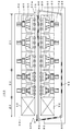
- FIG. 1 shows an example of the configuration of the reflow apparatus 100.
- the reflow device 100 includes a reflow device main body 40, a transport device 80, a heater 50, a fan 60, and a motor 62.
- the reflow device main body 40 is a tunnel-like housing having a carry-in port 40a and a carry-out port 40b, and includes a preheating zone Z1 and a main heating zone Z2 along a transfer path H1 from the carry-in port 40a to the carry-out port 40b. And a cooling zone Z3.
- the transport device 80 transports the printed circuit board 70 along the transport path H ⁇ b> 1 in the reflow device main body 40, and includes an endless chain 82 with a bush (hereinafter referred to as a chain 82) and a sprocket 86.
- the chain 82 is stretched by four sprockets 86 to which the rotational force of a driving motor (not shown) is transmitted, and the transport path H1 in the tunnel of the reflow device main body 40, the side and the lower side of the reflow device main body 40. It is laid to go around.
- the transport device 80 will be described later.
- the heater 50, the fan 60, and the motor 62 are installed in each of the preheating zone Z1 and the main heating zone Z2, and are arranged to face each other in the vertical direction of the transfer device 80.
- the heater 50 heats the gas inside the reflow apparatus main body 40 and generates hot hot air.
- the fan 60 is composed of, for example, a sirocco fan, and blows hot air heated by the heater 50 by rotation of the motor 62 from above and below the printed circuit board 70. As a result, the solder of the printed circuit board 70 is melted, and electronic components and the like are fixed to the electrodes of the printed circuit board 70.
- the heater 50, the fan 60, and the motor 62 installed in the preheating zone Z1 and the main heating zone Z2 have the same configuration.
- the cooling unit 92 includes, for example, a cooling member, a fan, a motor, and the like, and is installed in the cooling zone Z3.
- the cooling unit 92 solidifies the molten solder by cooling the printed circuit board 70 heated in the preheating zone Z1 and the main heating zone Z2.
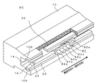
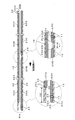
- FIG. 2 is a perspective view illustrating an example of a main part of the configuration of the transport device 80.
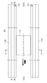
- FIG. 3 is a plan view illustrating a configuration example of the transport device 80.
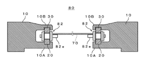
- FIG. 4 is a cross-sectional view taken along line AA of the transport device 80 shown in FIG.
- FIG. 5 is a cross-sectional view illustrating a configuration example of a main part of the transport device 80 illustrated in FIG. 4.
- FIG. 6 is a cross-sectional view taken along the line BB of the transport device 80 shown in FIG.
- the transport device 80 includes a transport rail (rail portion) 10, a chain 82, a lower key material 20, and an upper key material 30, as shown in FIGS.
- the transport rail 10 is composed of a pair of transport rails 10 and 10 arranged to face each other in the width direction of the printed circuit board 70, and the reflow apparatus main body 40. Are laid along the longitudinal direction (conveyance path H1).
- a metal material such as aluminum is used for the transport rail 10.
- the pair of transport rails 10 and 10 has a substantially U-shaped side surface opened on opposite sides, and has a lower rail 10A provided below the chain 82 and an upper rail 10B provided above the chain 82. is doing.
- a groove 12 for attaching the lower key material 20 is formed in the inner surface of the lower rail 10 ⁇ / b> A facing the upper rail 10 ⁇ / b> B along the longitudinal direction of the transport rail 10.
- the width W ⁇ b> 1 of the groove 12 is selected to be substantially the same as the width W ⁇ b> 2 of the lower key material 20, and the depth D ⁇ b> 1 is the chain 82 when the chain 82 is placed on the upper surface of the lower key material 20.
- the depth is such that the lower end of the inner plate 82a is not in contact with the inner surface of the lower rail 10A.
- the groove part 12 comprises an example of a 1st guide part.
- a groove 14 for attaching the upper key material 30 is formed along the longitudinal direction of the transport rail 10.
- the width W3 of the groove portion 14 is selected to be slightly larger than the width W4 of the upper key member 30, and a gap A1 is formed between the groove portion 14 and the upper key member 30.
- the depth D2 of the groove portion 14 is selected so that a slight gap A2 is formed between the upper surface of the upper key material 30 and the groove upper surface of the groove portion 14 when the upper key material 30 is disposed on the bush 82c of the chain 82.
- the groove part 14 comprises an example of a 2nd guide part.
- the chain 82 has a pair of inner plates 82a, 82a, a pair of outer plates 82b, 82b, a bush 82c, a pin 82d, and a holding pin 82e.
- the two inner plates 82a and 82a are press-fitted through a bush 82c and coupled.
- the pin 82d is inserted inside the bush 82c, and outer plates 82b and 82b are press-fitted and coupled to both ends of the pin 82d and outside the inner plates 82a and 82a, respectively.
- the holding pin 82e holds the printed circuit board 70, and is provided so as to protrude from the plate surface side of the outer plate 82b disposed on the transport rail 10 side facing each other.
- the printed circuit board 70 is placed on the holding pins 82e and is transported along the transport path H1.
- a pair of chains 82 is shown, but actually, a plurality of inner links having an inner plate 82a and a bush 82c and a plurality of outer links having an outer plate 82b and a pin 82d are alternately arranged. Concatenated and configured.
- the lower key member 20 is a long columnar body as shown in FIGS. 2 to 6, and is made of a metal material having excellent corrosion resistance and heat resistance, such as stainless steel (SUS).
- the lower key material 20 is fitted into the groove portion 12 so that the upper side of the lower key material 20 is exposed from the groove portion 12 and supports the bush 82c of the traveling chain 82 slidably on the upper surface portion thereof. Further, the lower key material 20 is fitted into the groove portion 12 without a gap, and is fixed to the groove portion 12 so as not to move in the transport path H1 and the direction orthogonal thereto.
- the width W2 of the lower key member 20 is selected to be substantially the same as the length of the bush 82c in the longitudinal direction.
- the lower key material 20 constitutes an example of a first support member.
- the lower key material 20 is divided into a plurality of key materials 20A, 20B, 20C, and 20D, and adjacent key materials 20A and 20B, key materials 20B and 20C, and key materials 20C and 20D. Is fitted into the groove 12 with a predetermined interval X1.
- the interval X1 is selected based on the expansion coefficient of the lower key material 20 and the like.
- the key materials 20B and 20C are shown for the sake of convenience as an example in which adjacent key materials are separated.
- the example which comprised the lower key material 20 by four is shown, it is not limited to this.
- a taper portion 22 that is inclined downward from the upper surface portion is provided at each of both ends in the longitudinal direction of the lower key material 20.
- a tapered portion 22a is provided at the end of the key member 20A on the carry-in port 40a side
- a tapered portion 22d is provided at the end of the key member 20D on the carry-out port 40b side.
- These tapered portions 22a and 22d function as guide portions for smoothly transporting the chain 82 inside and outside the tunnel of the reflow apparatus main body 40.
- a tapered portion 22b is provided at an end portion of the key material 20B facing the key material 20C
- a tapered portion 22c is provided at an end portion of the key material 20C facing the key material 20B.
- each lower key member 20 is fixed on the upstream side with respect to the conveyance path H1 of the printed circuit board 70, and the downstream side is a free end.
- a stopper 23 provided on the lower key material 20 is fixed by being inserted into the recess 11 of the groove 12. This is because when the lower key material 20 expands due to heat, the lower key material 20 is configured to expand in the transport direction side.
- the running direction of the chain 82 and the extending direction of the lower key material 20 coincide with each other, and therefore, the extension of the lower key material 20 is not subjected to stress due to the running of the chain 82. There will be no hindrance to the 82.
- the chain 82 travels to cause vibration of the lower key material 20 with the fixed side as a base point.
- the free end of the lower key material 20 is transferred to the transport path.
- the lower key material 20 is stretched in the direction opposite to the conveying direction due to the force that is lifted inward and hinders the chain traveling or due to heat, the chain 82 is traveling in the conveying direction.
- the extension of the lower key material 20 affects the travel of the chain 82, as stress is applied to the lower key material along with the expansion, and the lower key material 20 swells in the transport path and impedes the travel of the chain 82. May affect.
- the upper key material 30 is a long columnar body like the lower key material 20, and is made of a metal material having excellent corrosion resistance and heat resistance, such as stainless steel (SUS).
- the upper key member 30 is inserted into a space formed by the groove portion 14 and the chain 82, and is placed on the bush 82c of the chain 82 by its own weight. As a result, the bush 82c of the chain 82 slides in contact with the lower surface portion of the upper key member 30, and the inner plate 82a of the chain 82 is supported by the upper key member 30, thereby restricting the traveling direction of the chain 82. .
- a gap A1 is provided between the peripheral surface of the upper key member 30 and the groove peripheral surface of the groove portion 14, and between the upper surface of the upper key member 30 and the groove upper surface of the groove portion 14.
- a gap A2 is provided, and the upper key member 30 is disposed in the groove portion 14 with play. That is, the upper key member 30 is disposed in the groove portion 14 so as to be movable up and down and left and right through the gaps A1 and A2.
- the upper key member 30 constitutes an example of a second support member.
- the upper key member 30 is divided into a plurality of key members 30A, 30B, and 30C (support members). This is because the upper key member 30 is divided and smoothly attached to the groove portion 14.
- the plurality of key members 30A, 30B, and 30C are attached by sequentially inserting the lower key member 20 and the chain 82 into the space portion formed by the groove portion 14 and the chain 82. Therefore, a stopper 34 for preventing the previously inserted upper key material 30 (key material 30C) from dropping or jumping out from the carry-out port 40b side of the groove portion 14 is provided at the other end of the groove portion 14 on the carry-out port 40b side. Is provided.
- the upper key material 30 is composed of three, but the present invention is not limited to this.
- a taper portion 32 that is inclined from the lower surface portion toward the upper outside is provided at the end of the key material 30 ⁇ / b> A on the carry-in port 40 a side.
- the tapered portion 32 functions as a guide portion for ensuring a wide entrance of the chain 82 and smoothly transporting the chain 82 into the reflow apparatus main body 40.
- the end portion 30a of the upper key material 30 (key material 30A) on the carry-in port 40a side is a distance X2 from the end portion 20a on the carry-in port 40a side of the lower key material 20 (key material 20A). It is provided at a position shifted to the downstream side of the transport path H1. This is because, when the end portion 20a of the key material 20A and the end portion 30a of the key material 30A are set at the same position, the entrance between the key material 20A and the key material 30A becomes narrow, so the carry-in port 40a.
- the upper key material 30 is inserted into the space formed between the upper part of the chain 82 and the groove 14 of the transport rail 10 from the carry-in entrance 40a side. Since the upper key member 30 is divided into a plurality of pieces, these are sequentially inserted into the space portion. Since the stop portion 34 is provided on the carry-out port 40 b side of the groove portion 14, the upper key material 30 is pushed in until the previously inserted upper key material 30 is stopped by the stop portion 34. In this way, the transport device 80 can be configured.
- the upper key member 30 is movably disposed in the groove portion 14 via the gaps A1 and A2, even when the chain 82 vibrates during running, Since the key member 30 can absorb the vibration in the vertical direction of the chain 82, the chain 82 can be driven stably. Further, even when the upper key material 30 and the chain 82 are expanded by the material, the upper key material 30 can absorb the expansion in the range of the gaps A1 and A2, so that the chain 82 can be run stably. . As a result, the situation where the operation of the chain 82 stops can be avoided.
- the technical scope of the present invention is not limited to the above-described embodiment, and includes those in which various modifications are made to the above-described embodiment without departing from the spirit of the present invention.
- the guide portion may be formed in a convex shape instead of the groove. .
- the key material may be provided with a concave portion so as to engage with the convex portion.
- this invention is applicable also to a flow type soldering apparatus and the similar conveying apparatus.
Landscapes
- Engineering & Computer Science (AREA)
- Mechanical Engineering (AREA)
- Manufacturing & Machinery (AREA)
- Microelectronics & Electronic Packaging (AREA)
- Electric Connection Of Electric Components To Printed Circuits (AREA)
Abstract
基板を搬送するチェーンの走行を安定させるために、本発明は、リフロー装置のトンネル内にはプリント基板を搬送する搬送レール(10)が敷設され、搬送レール(10)の下部レール(10A)には溝部(12)が形成され、上部レール(10B)には溝部(14)が形成され、下部キー材(20)は、溝部(12)に嵌め込まれ、チェーン(82)の下部を支持し、上部キー材(30)は、その自重によりチェーン(82)のブッシュ(82c)の上面に載置されると共に、溝部(14)に隙間(A1),(A2)を介して移動可能に配置され、チェーン(82)の上部を支持する。また、本発明によれば、例えば、チェーンが走行中に振動した場合、上部キー材(30)によってチェーン(82)の上下方向の振動が吸収され、チェーンの安定した走行が確保される。
Description
本発明は、基板のはんだ付けを行うはんだ付け装置の基板搬送等に使用される搬送装置に関する。詳しくは、チェーンの上部を支持する第2の支持部材をレール部の第2の溝部に隙間を介して移動可能に配置することで、チェーンの振動や膨張等を吸収してチェーンを安定して走行させるものである。
プリント基板と電子部品とのはんだ付けを行う場合には、一般にはんだ付け装置が利用される。はんだ付け装置は、一般的にリフロー方式とフロー方式に大別できる。リフロー方式のはんだ付け装置では、基板を搬送する搬送装置と、トンネル状のリフロー装置本体(マッフル)とを備えている。リフロー装置本体の内部には、予備加熱ゾーンと本加熱ゾーンと冷却ゾーンとが設けられている。メタルマスクによってソルダ―ペーストをプリント基板に印刷し、電子部品を載置した後に、予備加熱ゾーンおよび本加熱ゾーンでは、搬送装置によって搬送された基板に対して熱風を吹き付けて、ソルダ―ペーストのはんだを溶融させて基板の電極に電子部品等を固着させる。冷却ゾーンでは、予備加熱ゾーンおよび本加熱ゾーンで加熱された基板を冷却してはんだを固化させる。このような一連の処理により、プリント基板のはんだ付けが行われる。
搬送装置には、高温環境に対する耐熱性や耐熱強度が必要とされるため、一般にブッシュ付きチェーンが使用されている。ブッシュ付きチェーンは、基板の両端を支持するために一対で構成され、リフロー装置本体のトンネル内に沿って走行している。一対のブッシュ付きチェーンの対向するプレート面には、基板を保持するための複数の保持ピンが設けられ、この保持ピンに基板が載置されることで、基板がリフロー装置本体のトンネル内の各ゾーンに搬送される。
ここで、リフロー装置を走行するブッシュ付きチェーンにおいては、走行中に一対のチェーン間の間隔が広くなったり、チェーンの振動が激しくなる場合があり、保持ピンに載置されたプリント基板が落下したり、基板の搬送不良によりはんだ付け処理に影響を及ぼすことがあった。
このチェーンの搬送不良を防止するために、チェーンの上部および下部のそれぞれにチェーンの走行をガイドするガイド部材を設けたリフローはんだ付け装置が提案されている(特許文献1参照)。例えば、このはんだ付け装置では、上部チェーンガイドと中間部チェーンガイドとによって上段に配置されたチェーンを支持することで、チェーンの安定した走行を図っている。
しかしながら、上記特許文献1に開示されるリフローはんだ付け装置では以下のような問題がある。すなわち、上部チェーンガイドはチェーン上部に接触すると共に上部支持部に一体形成され、中間部チェーンガイドはチェーン下部に接触すると共に支持部材に固定された構成となっており、チェーンが上部チェーンガイドと中間部チェーンガイドとの間に隙間なく固定して取り付けられている。そのため、チェーンが走行中に振動した場合には、チェーンの振動を上部チェーンガイドおよび中間部チェーンガイドで吸収できず、その振動によってチェーンの動作が停止してしまうという問題がある。また、上部チェーンガイドや中間部チェーンガイドの材質による膨張によりチェーンが押圧され、チェーンの動作が停止してしまうという問題もある。
また、フロー方式のはんだ付け装置では、あらかじめ溶融しているはんだを上方に向けて噴流させ、噴流面にプリント基板を接触させてはんだ付けを行う装置であって、上述のリフロー装置と同様な搬送装置を有しているため、同様の問題を抱えている。さらに、はんだ付け装置に拘わらずに、この種の搬送装置においても同様の問題を抱えている。
そこで、本発明は、上記課題を解決するものであって、基板を搬送するチェーンの走行を安定させることを可能とした搬送装置を提供することを目的とする。
上述した課題を解決するために、搬送用チェーンと、チェーンの下方に設けられた第1の案内部とチェーンの上方に設けられた第2の案内部とを有し、チェーンを基板の搬送方向に沿って走行させるレール部と、レール部の第1の案内部に取り付けられ、チェーンの下部を支持する第1の支持部材と、レール部の第2の案内部に移動可能に配置され、チェーンの上部を支持する第2の支持部材とを備えるものである。
本発明において、第2の支持部材は、第2の案内部に間隙を介して配置され、隙間の範囲内で移動可能に構成されている。そのため、チェーンが走行中に振動した場合、第2の支持部材によってチェーンの振動が吸収され、チェーンの安定した走行が確保される。また、第2の支持部材やチェーンがその材質により膨張した場合でも、第2の支持部材によって隙間の範囲で膨張が吸収され、チェーンの動作が停止する事態を回避できる。
本発明によれば、第2の支持部材を第2の案内部に間隙を介して移動可能に配置するので、チェーンが走行中に振動した場合、第2の支持部材によってチェーンの振動を吸収でき、その結果、チェーンを安定して走行させることができる。
以下、一例としてリフロー装置に適用される搬送装置に発明を実施した場合の最良の形態(以下実施の形態とする)について説明する。
[リフロー装置の構成例]
まず、本発明の一実施形態に係るリフロー装置100の概略構成について説明する。図1は、リフロー装置100の構成の一例を示している。図1に示すように、リフロー装置100は、リフロー装置本体40と搬送装置80とヒータ50とファン60とモータ62とを備えている。リフロー装置本体40は、搬入口40aと搬出口40bとを有するトンネル状の匡体であって、搬入口40aから搬出口40bに至る搬送経路H1に沿って予備加熱ゾーンZ1と本加熱ゾーンZ2と冷却ゾーンZ3とを有している。
[リフロー装置の構成例]
まず、本発明の一実施形態に係るリフロー装置100の概略構成について説明する。図1は、リフロー装置100の構成の一例を示している。図1に示すように、リフロー装置100は、リフロー装置本体40と搬送装置80とヒータ50とファン60とモータ62とを備えている。リフロー装置本体40は、搬入口40aと搬出口40bとを有するトンネル状の匡体であって、搬入口40aから搬出口40bに至る搬送経路H1に沿って予備加熱ゾーンZ1と本加熱ゾーンZ2と冷却ゾーンZ3とを有している。
搬送装置80は、リフロー装置本体40内の搬送経路H1に沿ってプリント基板70を搬送するものであり、無端状のブッシュ付きチェーン82(以下チェーン82という)とスプロケット86とを有している。チェーン82は、図示しない駆動用モータの回転力が伝達された4個のスプロケット86によって張架された状態で、リフロー装置本体40のトンネル内の搬送経路H1、リフロー装置本体40の側方および下方を周回するように敷設されている。なお、搬送装置80については後述する。
ヒータ50、ファン60およびモータ62は、予備加熱ゾーンZ1および本加熱ゾーンZ2のそれぞれに設置され、搬送装置80の上下方向のそれぞれに対向して配置されている。ヒータ50は、リフロー装置本体40内部の気体を加熱させて高温の熱風を生成する。ファン60は、例えばシロッコファンからなり、モータ62の駆動により回転駆動してヒータ50によって加熱された熱風をプリント基板70の上下方向から吹き付ける。これにより、プリント基板70のはんだが溶融され、プリント基板70の電極に電子部品等が固着される。なお、本例では、予備加熱ゾーンZ1および本加熱ゾーンZ2に設置されるヒータ50、ファン60およびモータ62は、同一の構成のものを用いている。
冷却部92は、例えば冷却部材とファンとモータ等を有し、冷却ゾーンZ3に設置されている。冷却部92は、予備加熱ゾーンZ1および本加熱ゾーンZ2で加熱されたプリント基板70を冷却して溶融したはんだを固化する。
[搬送装置の構成例]
次に、搬送装置80の構成の一例について説明する。図2は、搬送装置80の構成の要部の一例を示す斜視図である。図3は、搬送装置80の構成例を示す平面図である。図4は、図3に示す搬送装置80のA-A線に沿った断面図である。図5は、図4に示す搬送装置80の要部の構成例を示す断面図である。図6は、図3に示す搬送装置80のB-B線に沿った断面図である。
次に、搬送装置80の構成の一例について説明する。図2は、搬送装置80の構成の要部の一例を示す斜視図である。図3は、搬送装置80の構成例を示す平面図である。図4は、図3に示す搬送装置80のA-A線に沿った断面図である。図5は、図4に示す搬送装置80の要部の構成例を示す断面図である。図6は、図3に示す搬送装置80のB-B線に沿った断面図である。
搬送装置80は、図2~図6に示すように、搬送レール(レール部)10とチェーン82と下部キー材20と上部キー材30とを有している。搬送レール10は、図4に示すように、プリント基板70の幅方向の両端部のそれぞれを支持するために、対向して配置された一対の搬送レール10,10で構成され、リフロー装置本体40の長手方向(搬送経路H1)に沿うようにして敷設されている。搬送レール10には、例えばアルミニウム等の金属材料が用いられる。
一対の搬送レール10,10は、互いに対向する側が開口した側面略コの字形状をなし、チェーン82の下方に設けられた下部レール10Aとチェーン82の上方に設けられた上部レール10Bとを有している。下部レール10Aの上部レール10Bと対向した内面部には、下部キー材20を取り付けるための溝部12が搬送レール10の長手方向に沿って形成されている。図5に示すように、溝部12の幅W1は、下部キー材20の幅W2と略同一に選定され、その深さD1は下部キー材20の上面にチェーン82を載置したときにチェーン82を構成する内プレート82aの下端が下部レール10Aの内面部に接触しないような深さとされる。なお、溝部12は、第1の案内部の一例を構成している。
上部レール10Bの下部レール10Aと対向した内面部には、上部キー材30を取り付けるための溝部14が搬送レール10の長手方向に沿って形成されている。図5に示すように、溝部14の幅W3は、上部キー材30の幅W4よりも若干広くなるように選定され、溝部14と上部キー材30との間に隙間A1ができるように構成される。溝部14の深さD2は、上部キー材30をチェーン82のブッシュ82c上に配置したときに上部キー材30の上面と溝部14の溝上面との間に若干の隙間A2ができるように選定される。なお、溝部14は、第2の案内部の一例を構成している。
チェーン82は、図5に示すように、一対の内プレート82a,82aと一対の外プレート82b,82bとブッシュ82cとピン82dと保持ピン82eとを有している。2枚の内プレート82a,82aはブッシュ82cを介して圧入して結合されている。ピン82dはブッシュ82cの内側に挿入され、ピン82dの両端でかつ内プレート82a,82aの外側のそれぞれには外プレート82b,82bが圧入して結合されている。保持ピン82eは、プリント基板70を保持するものであり、互いに対向する搬送レール10側に配置された外プレート82bのプレート面側に突出して設けられている。プリント基板70は、保持ピン82e上に載置されて搬送経路H1に沿って搬送される。なお、本例では、一組のチェーン82を示しているが、実際には、内プレート82aおよびブッシュ82cを有する複数の内リンクと、外プレート82bおよびピン82dを有する複数の外リンクとが交互に連結されて構成される。
下部キー材20は、図2~図6に示すように、長尺の柱状体であって、例えばステンレス(SUS)等の耐食性、耐熱性に優れた金属材料から構成されている。下部キー材20は、溝部12に嵌め込まれ、下部キー材20の上部側が溝部12から露出した状態とされ、走行するチェーン82のブッシュ82cをその上面部でスライド可能に支持する。また、下部キー材20は、溝部12に対して隙間なく嵌め込まれ、搬送経路H1およびこれに直交する方向に移動しないように溝部12に固定されている。下部キー材20の幅W2は、ブッシュ82cの長手方向の長さと略同一に選定される。なお、下部キー材20は、第1の支持部材の一例を構成している。
下部キー材20は、図6に示すように、複数のキー材20A,20B,20C,20Dに分割されて構成され、隣接するキー材20A,20B、キー材20B,20C、キー材20C,20Dが所定の間隔X1を隔てて溝部12に嵌め込まれている。これは、例えば下部キー材20の材質に基づく膨張により下部キー材20が伸張する場合があるので、隣接する下部キー材20間にある程度のクリアランスを持たせておく必要があるからである。したがって、間隔X1は、下部キー材20の膨張率等に基づいて選定される。なお、図6では、隣接するキー材を離間させた例を便宜上キー材20B,20Cのみ示している。また、下部キー材20を4本で構成した例を示しているが、これに限定されることはない。
下部キー材20の長手方向の両端部のそれぞれには、その上面部から下方に向かって傾斜したテーパー部22が設けられている。具体的には、キー材20Aの搬入口40a側の端部にはテーパー部22aが設けられ、キー材20Dの搬出口40b側の端部にはテーパー部22dが設けられている。これらのテーパー部22a,22dは、リフロー装置本体40のトンネル内部および外部にチェーン82を円滑に搬送するためのガイド部として機能する。また、キー材20Bのキー材20Cと対向した端部にはテーパー部22bが設けられ、キー材20Cのキー材20Bと対向した端部にはテーパー部22cが設けられている。これらのテーパー部22b,22cは、リフロー装置本体40のトンネル内部でチェーン82を円滑に搬送するためのガイド部として機能する。
なお、本例では、各下部キー材20は、図6に示すように、プリント基板70の搬送経路H1に対して上流側において、固定されており、下流側は自由端となっている。具体的には下部キー材20に設けられたストッパー23が、溝部12の凹部11に挿入されることで、固定されるようにしている。これは、熱によって下部キー材20が膨張した場合に、下部キー材20が、搬送方向側に伸張するように構成するためである。これによって、チェーン82の走行方向と下部キー材20の伸張方向とが一致するため、下部キー材20の伸張がチェーン82の走行によってストレスを受けることがないため、下部キー材20の伸張がチェーン82の走行に支障を来たすことがない。下流側を固定し上流側を自由端とした場合には、チェーン82の走行によって下部キー材20に固定側を基点とした振動が発生し、その結果、下部キー材20の自由端が搬送経路内に持ち上がる力を受け、チェーン走行に支障をきたしたり、熱によって、下部キー材20は搬送方向と反対側に伸張する一方でチェーン82は搬送方向に走行しているので、下部キー材20の伸張に伴って下部キー材にストレスが加わり、搬送経路内に下部キー材20が膨らんでしまい、チェーン82の走行を阻害するというような、下部キー材20の伸張がチェーン82の走行に影響を及ぼす場合がある。
上部キー材30は、下部キー材20と同様に、長尺の柱状体であって、例えばステンレス(SUS)等の耐食性、耐熱性に優れた金属材料から構成されている。上部キー材30は、溝部14とチェーン82とで構成される空間部に挿入され、自重によりチェーン82のブッシュ82c上に載置される。これにより、チェーン82のブッシュ82cが上部キー材30の下面部に接触した状態でスライドし、チェーン82の内プレート82aが上部キー材30によって支持されることでチェーン82の走行方向が規制される。
図5に示すように、上部キー材30の周面と溝部14の溝周面との間には隙間A1が設けられると共に、上部キー材30の上面と溝部14の溝上面との間には隙間A2が設けられ、上部キー材30は遊びを有した状態で溝部14に配置される。すなわち、上部キー材30は、隙間A1,A2を介して上下左右に移動可能に溝部14に配置される。なお、上部キー材30は、第2の支持部材の一例を構成している。
また、上部キー材30は、図6に示すように、複数のキー材30A,30B,30C(支持部材)に分割されて構成されている。これは、上部キー材30を分割することで溝部14に円滑に取り付けるためである。ここで、複数のキー材30A,30B,30Cは、下部キー材20およびチェーン82を取り付けた後に、溝部14とチェーン82とで構成される空間部に順次に挿入することで取り付けが行われる。そのため、溝部14の搬出口40b側の他端には、先に挿入した上部キー材30(キー材30C)が溝部14の搬出口40b側から落下または飛び出ないようにするための止め部34が設けられている。なお、本例では、上部キー材30を3本で構成した例を示しているが、これに限定されることはない。
キー材30Aの搬入口40a側の端部には、図6に示すように、その下面部から外側上方に向かって傾斜したテーパー部32が設けられている。このテーパー部32は、チェーン82の進入口を広く確保して、チェーン82をリフロー装置本体40の内部に円滑に搬送するためのガイド部として機能する。
上部キー材30(キー材30A)の搬入口40a側の端部30aは、図6に示すように、下部キー材20(キー材20A)の搬入口40a側の端部20aよりも距離X2だけ搬送経路H1の下流側にずれた位置に設けられている。これは、キー材20Aの端部20aとキー材30Aの端部30aとを同一位置とした場合には、キー材20Aとキー材30Aと間の進入口が狭くなってしまうため、搬入口40aから搬入されるチェーン82がキー材20A,30Aに接触して噛み込み、チェーン82の走行が停止してしまう場合があるからである。上部キー材30(キー材30A)と下部キー材20(キー材20A)とをずらして配置することで、進入口の開口が広くなり、搬入口40aから搬入されるチェーン82を下部キー材20でガイドしてから、上部キー材30でチェーン82をガイドするので、チェーン82の噛み込みを防止でき、安定したチェーン82の走行を確保できる。
[搬送装置(キー材)の組み立て例]
次に、搬送装置80の組み立ての一例について図2~図6を用いて説明する。まず、下部キー材20を溝部12の所定位置に嵌め込む。このとき、上述したように、ストッパー23を凹部11に挿入し、隣接する下部キー材20,20同士は、所定の間隔X1を隔てて溝部14に嵌め込む。続けて、下部キー材20の上面部に、連結していない状態のチェーン82を下部キー材20をガイドとして取り付けた後に、4箇所のスプロケット86にチェーン82を張架させた状態でチェーン82を連結する。
次に、搬送装置80の組み立ての一例について図2~図6を用いて説明する。まず、下部キー材20を溝部12の所定位置に嵌め込む。このとき、上述したように、ストッパー23を凹部11に挿入し、隣接する下部キー材20,20同士は、所定の間隔X1を隔てて溝部14に嵌め込む。続けて、下部キー材20の上面部に、連結していない状態のチェーン82を下部キー材20をガイドとして取り付けた後に、4箇所のスプロケット86にチェーン82を張架させた状態でチェーン82を連結する。
次に、上部キー材30を、チェーン82の上部と搬送レール10の溝部14との間に形成される空間部に搬入口40a側から挿入する。上部キー材30は、複数本に分割されているので、これらを順次、空間部に挿入して行く。溝部14の搬出口40b側には、止め部34が設けられているので、先に挿入した上部キー材30が止め部34によって停止するまで上部キー材30を押し込む。このようにして、搬送装置80を構成することができる。
以上説明したように、本実施の形態によれば、上部キー材30は、溝部14に隙間A1,A2を介して移動可能に配置されるため、チェーン82が走行中に振動した場合でも、上部キー材30によってチェーン82の上下方向の振動を吸収することができるので、チェーン82を安定させて走行させることができる。また、上部キー材30やチェーン82がその材質により膨張した場合でも、上部キー材30が隙間A1,A2の範囲で膨張を吸収することができるので、チェーン82を安定させて走行させることができる。その結果、チェーン82の動作が停止してしまう事態を回避できる。
なお、本発明の技術範囲は、上述した実施形態に限定されるものではなく、本発明の趣旨を逸脱しない範囲において、上述した実施形態に種々の変更を加えたものを含む。上述の実施の形態においては、第1及び第2の案内部として、溝部12及び溝部14として構成した場合につき説明したが、溝に代えて凸部状に案内部を形成するようにしても良い。このように案内部を凸部状に形成した場合、この凸部に係合するようにキー材に凹部を設ければ良い。
さらに、一例としてリフロー装置に適用される搬送装置の給油装置に本発明を実施した場合について説明したが、フロー方式のはんだ付け装置や同様の搬送装置においても本発明を適用できる。
10・・・搬送レール、12,14・・・溝部、20・・・下部キー材、22,22a,22b,22c,22d・・・テーパー部、20A,20B,20C,20D・・・支持部材、30・・・上部キー材、30A,30B,30D・・・支持部材、32・・・テーパー部、82・・・ブッシュ付きチェーン
Claims (7)
- 搬送用チェーンと、
前記チェーンの下方に設けられた第1の案内部と前記チェーンの上方に設けられた第2の案内部とを有し、前記チェーンを前記基板の搬送方向に沿って走行させるレール部と、
前記レール部の前記第1の案内部に取り付けられ、前記チェーンの下部を支持する第1の支持部材と、
前記レール部の前記第2の案内部に移動可能に配置され、前記チェーンの上部を支持する第2の支持部材と
を備えることを特徴とする搬送装置。 - 前記第1の支持部材は、前記基板の搬送方向に対して伸張可能なように、前記案内部に搬送方向の上流側が固定されていることを特徴とする請求項1に記載の搬送装置。
- 前記第1の支持部材は、複数の支持部材で構成され、
互いに隣接する前記支持部材が所定の間隔を隔てて配置された
ことを特徴とする請求項1または請求項2に記載の搬送装置。 - 前記第1の支持部材の長手方向の両端部の少なくとも一方は、前記チェーンと対向する面がテーパー面とされたことを特徴とする請求項1乃至請求項3のいずれか一項に記載の搬送装置。
- 前記第2の支持部材の前記基板の搬入口側端部は、前記第1の支持部材の搬入口側端部から所定の距離だけ搬送経路の下流側にずれて配置された
ことを特徴とする請求項1乃至請求項4のいずれか一項に記載の搬送装置。 - 前記第2の支持部材の前記基板の搬入口側端部は、前記チェーンと対向する面がテーパー面とされた
ことを特徴とする請求項1乃至請求項5のいずれか一項に記載の搬送装置。 - 前記第2の支持部材は、複数の支持部材で構成された
ことを特徴とする請求項1乃至請求項6のいずれか一項に記載の搬送装置。
Priority Applications (1)
| Application Number | Priority Date | Filing Date | Title |
|---|---|---|---|
| CN201180055615.9A CN103221171B (zh) | 2010-11-19 | 2011-11-16 | 输送装置 |
Applications Claiming Priority (2)
| Application Number | Priority Date | Filing Date | Title |
|---|---|---|---|
| JP2010258596A JP5299409B2 (ja) | 2010-11-19 | 2010-11-19 | 搬送装置 |
| JP2010-258596 | 2010-11-19 |
Publications (1)
| Publication Number | Publication Date |
|---|---|
| WO2012067155A1 true WO2012067155A1 (ja) | 2012-05-24 |
Family
ID=46084078
Family Applications (1)
| Application Number | Title | Priority Date | Filing Date |
|---|---|---|---|
| PCT/JP2011/076426 Ceased WO2012067155A1 (ja) | 2010-11-19 | 2011-11-16 | 搬送装置 |
Country Status (3)
| Country | Link |
|---|---|
| JP (1) | JP5299409B2 (ja) |
| CN (1) | CN103221171B (ja) |
| WO (1) | WO2012067155A1 (ja) |
Families Citing this family (2)
| Publication number | Priority date | Publication date | Assignee | Title |
|---|---|---|---|---|
| CN102745457A (zh) * | 2012-07-05 | 2012-10-24 | 无锡金洋铝业有限公司 | 一种异型双t型轨道 |
| CN117066625A (zh) * | 2023-08-30 | 2023-11-17 | 四川景恒科技有限公司 | 一种多腔室隧道真空回流焊炉 |
Citations (7)
| Publication number | Priority date | Publication date | Assignee | Title |
|---|---|---|---|---|
| JPS61200654U (ja) * | 1985-06-07 | 1986-12-16 | ||
| JPH01118091A (ja) * | 1987-10-30 | 1989-05-10 | Matsushita Electric Ind Co Ltd | 加熱炉用搬送装置 |
| JPH03216268A (ja) * | 1990-01-22 | 1991-09-24 | Toyo Radiator Co Ltd | 熱交換器ろう付け用ハンガ |
| JPH0486609U (ja) * | 1990-11-30 | 1992-07-28 | ||
| JPH04344869A (ja) * | 1991-05-17 | 1992-12-01 | Denkoo:Kk | 熱処理装置 |
| JPH0645747A (ja) * | 1992-07-23 | 1994-02-18 | Matsushita Electric Ind Co Ltd | リフロー装置 |
| JP2003179342A (ja) * | 2001-12-10 | 2003-06-27 | Senju Metal Ind Co Ltd | リフロー炉 |
Family Cites Families (9)
| Publication number | Priority date | Publication date | Assignee | Title |
|---|---|---|---|---|
| JPS61200654A (ja) * | 1985-02-28 | 1986-09-05 | Futaba Corp | 螢光表示装置 |
| JPH01133668A (ja) * | 1987-11-20 | 1989-05-25 | Kenji Kondo | プリント基板の保持搬送方法およびその装置 |
| JPH0486609A (ja) * | 1990-07-27 | 1992-03-19 | Sumitomo Electric Ind Ltd | 光コネクタ |
| JP4401537B2 (ja) * | 2000-05-26 | 2010-01-20 | 千住金属工業株式会社 | リフロー炉 |
| JP2002037431A (ja) * | 2000-07-27 | 2002-02-06 | Nec Saitama Ltd | 板状物体の搬送機構及びリフロー装置 |
| JP4559656B2 (ja) * | 2001-04-03 | 2010-10-13 | 株式会社タムラ製作所 | 搬送装置および加熱装置 |
| MY131417A (en) * | 2002-11-25 | 2007-08-30 | Senju Metal Industry Co | Solder reflow oven |
| CN100522444C (zh) * | 2003-12-26 | 2009-08-05 | 株式会社田村制作所 | 焊锡连接装置 |
| TW200524496A (en) * | 2004-01-07 | 2005-07-16 | Senju Metal Industry | Reflow furnace |
-
2010
- 2010-11-19 JP JP2010258596A patent/JP5299409B2/ja active Active
-
2011
- 2011-11-16 WO PCT/JP2011/076426 patent/WO2012067155A1/ja not_active Ceased
- 2011-11-16 CN CN201180055615.9A patent/CN103221171B/zh active Active
Patent Citations (7)
| Publication number | Priority date | Publication date | Assignee | Title |
|---|---|---|---|---|
| JPS61200654U (ja) * | 1985-06-07 | 1986-12-16 | ||
| JPH01118091A (ja) * | 1987-10-30 | 1989-05-10 | Matsushita Electric Ind Co Ltd | 加熱炉用搬送装置 |
| JPH03216268A (ja) * | 1990-01-22 | 1991-09-24 | Toyo Radiator Co Ltd | 熱交換器ろう付け用ハンガ |
| JPH0486609U (ja) * | 1990-11-30 | 1992-07-28 | ||
| JPH04344869A (ja) * | 1991-05-17 | 1992-12-01 | Denkoo:Kk | 熱処理装置 |
| JPH0645747A (ja) * | 1992-07-23 | 1994-02-18 | Matsushita Electric Ind Co Ltd | リフロー装置 |
| JP2003179342A (ja) * | 2001-12-10 | 2003-06-27 | Senju Metal Ind Co Ltd | リフロー炉 |
Also Published As
| Publication number | Publication date |
|---|---|
| CN103221171A (zh) | 2013-07-24 |
| CN103221171B (zh) | 2015-04-15 |
| JP2012106273A (ja) | 2012-06-07 |
| JP5299409B2 (ja) | 2013-09-25 |
Similar Documents
| Publication | Publication Date | Title |
|---|---|---|
| JP4993015B2 (ja) | 搬送装置の給油装置 | |
| JP5463129B2 (ja) | リフロー装置 | |
| US8186563B2 (en) | Automatic soldering device and carrier device | |
| JP5299409B2 (ja) | 搬送装置 | |
| JP2012106273A5 (ja) | ||
| JP6133631B2 (ja) | リフロー装置 | |
| JP5264079B2 (ja) | 加熱装置 | |
| JP4073861B2 (ja) | リフロー炉 | |
| JP7550253B2 (ja) | 搬送加熱装置 | |
| JP2016525031A (ja) | 移送装置、特に延伸装置用サイド案内レール | |
| JP2003179342A (ja) | リフロー炉 | |
| JP3211354B2 (ja) | リフロー加熱装置 | |
| JP2002240920A (ja) | 搬送装置および加熱装置 | |
| JP4784796B2 (ja) | 搬送コンベアを有する機器における被搬送物の固定用治具 | |
| JP2005197302A (ja) | 搬送装置 | |
| JPH032375Y2 (ja) | ||
| JP2010067881A (ja) | リフロー装置 | |
| KR200255705Y1 (ko) | 납땜 장치용 인쇄회로기판 이송 장치 | |
| JP2002100864A (ja) | リフロー半田付け装置 | |
| JPH0918134A (ja) | 加熱装置における被加熱板の搬送方法 | |
| JP2013004789A (ja) | リフロー装置 | |
| JP2022071912A (ja) | グリス供給ユニット及び搬送加熱装置 | |
| JPH0550222A (ja) | 自動半田付装置 | |
| JPH06194052A (ja) | 不活性ガス雰囲気炉 | |
| JP2006032679A (ja) | プリント基板の反り防止治具 |
Legal Events
| Date | Code | Title | Description |
|---|---|---|---|
| 121 | Ep: the epo has been informed by wipo that ep was designated in this application |
Ref document number: 11841707 Country of ref document: EP Kind code of ref document: A1 |
|
| DPE2 | Request for preliminary examination filed before expiration of 19th month from priority date (pct application filed from 20040101) | ||
| NENP | Non-entry into the national phase |
Ref country code: DE |
|
| 122 | Ep: pct application non-entry in european phase |
Ref document number: 11841707 Country of ref document: EP Kind code of ref document: A1 |