WO2012063572A1 - 電動車両のブレーキ制御装置 - Google Patents
電動車両のブレーキ制御装置 Download PDFInfo
- Publication number
- WO2012063572A1 WO2012063572A1 PCT/JP2011/072601 JP2011072601W WO2012063572A1 WO 2012063572 A1 WO2012063572 A1 WO 2012063572A1 JP 2011072601 W JP2011072601 W JP 2011072601W WO 2012063572 A1 WO2012063572 A1 WO 2012063572A1
- Authority
- WO
- WIPO (PCT)
- Prior art keywords
- brake
- motor
- value
- vehicle speed
- target deceleration
- Prior art date
Links
Images


Classifications
-
- B—PERFORMING OPERATIONS; TRANSPORTING
- B60—VEHICLES IN GENERAL
- B60T—VEHICLE BRAKE CONTROL SYSTEMS OR PARTS THEREOF; BRAKE CONTROL SYSTEMS OR PARTS THEREOF, IN GENERAL; ARRANGEMENT OF BRAKING ELEMENTS ON VEHICLES IN GENERAL; PORTABLE DEVICES FOR PREVENTING UNWANTED MOVEMENT OF VEHICLES; VEHICLE MODIFICATIONS TO FACILITATE COOLING OF BRAKES
- B60T8/00—Arrangements for adjusting wheel-braking force to meet varying vehicular or ground-surface conditions, e.g. limiting or varying distribution of braking force
- B60T8/17—Using electrical or electronic regulation means to control braking
-
- B—PERFORMING OPERATIONS; TRANSPORTING
- B60—VEHICLES IN GENERAL
- B60T—VEHICLE BRAKE CONTROL SYSTEMS OR PARTS THEREOF; BRAKE CONTROL SYSTEMS OR PARTS THEREOF, IN GENERAL; ARRANGEMENT OF BRAKING ELEMENTS ON VEHICLES IN GENERAL; PORTABLE DEVICES FOR PREVENTING UNWANTED MOVEMENT OF VEHICLES; VEHICLE MODIFICATIONS TO FACILITATE COOLING OF BRAKES
- B60T13/00—Transmitting braking action from initiating means to ultimate brake actuator with power assistance or drive; Brake systems incorporating such transmitting means, e.g. air-pressure brake systems
- B60T13/10—Transmitting braking action from initiating means to ultimate brake actuator with power assistance or drive; Brake systems incorporating such transmitting means, e.g. air-pressure brake systems with fluid assistance, drive, or release
- B60T13/12—Transmitting braking action from initiating means to ultimate brake actuator with power assistance or drive; Brake systems incorporating such transmitting means, e.g. air-pressure brake systems with fluid assistance, drive, or release the fluid being liquid
- B60T13/16—Transmitting braking action from initiating means to ultimate brake actuator with power assistance or drive; Brake systems incorporating such transmitting means, e.g. air-pressure brake systems with fluid assistance, drive, or release the fluid being liquid using pumps directly, i.e. without interposition of accumulators or reservoirs
- B60T13/20—Transmitting braking action from initiating means to ultimate brake actuator with power assistance or drive; Brake systems incorporating such transmitting means, e.g. air-pressure brake systems with fluid assistance, drive, or release the fluid being liquid using pumps directly, i.e. without interposition of accumulators or reservoirs with control of pump driving means
-
- B—PERFORMING OPERATIONS; TRANSPORTING
- B60—VEHICLES IN GENERAL
- B60T—VEHICLE BRAKE CONTROL SYSTEMS OR PARTS THEREOF; BRAKE CONTROL SYSTEMS OR PARTS THEREOF, IN GENERAL; ARRANGEMENT OF BRAKING ELEMENTS ON VEHICLES IN GENERAL; PORTABLE DEVICES FOR PREVENTING UNWANTED MOVEMENT OF VEHICLES; VEHICLE MODIFICATIONS TO FACILITATE COOLING OF BRAKES
- B60T13/00—Transmitting braking action from initiating means to ultimate brake actuator with power assistance or drive; Brake systems incorporating such transmitting means, e.g. air-pressure brake systems
- B60T13/10—Transmitting braking action from initiating means to ultimate brake actuator with power assistance or drive; Brake systems incorporating such transmitting means, e.g. air-pressure brake systems with fluid assistance, drive, or release
- B60T13/58—Combined or convertible systems
- B60T13/585—Combined or convertible systems comprising friction brakes and retarders
- B60T13/586—Combined or convertible systems comprising friction brakes and retarders the retarders being of the electric type
-
- B—PERFORMING OPERATIONS; TRANSPORTING
- B60—VEHICLES IN GENERAL
- B60T—VEHICLE BRAKE CONTROL SYSTEMS OR PARTS THEREOF; BRAKE CONTROL SYSTEMS OR PARTS THEREOF, IN GENERAL; ARRANGEMENT OF BRAKING ELEMENTS ON VEHICLES IN GENERAL; PORTABLE DEVICES FOR PREVENTING UNWANTED MOVEMENT OF VEHICLES; VEHICLE MODIFICATIONS TO FACILITATE COOLING OF BRAKES
- B60T8/00—Arrangements for adjusting wheel-braking force to meet varying vehicular or ground-surface conditions, e.g. limiting or varying distribution of braking force
- B60T8/17—Using electrical or electronic regulation means to control braking
- B60T8/1755—Brake regulation specially adapted to control the stability of the vehicle, e.g. taking into account yaw rate or transverse acceleration in a curve
-
- B—PERFORMING OPERATIONS; TRANSPORTING
- B60—VEHICLES IN GENERAL
- B60T—VEHICLE BRAKE CONTROL SYSTEMS OR PARTS THEREOF; BRAKE CONTROL SYSTEMS OR PARTS THEREOF, IN GENERAL; ARRANGEMENT OF BRAKING ELEMENTS ON VEHICLES IN GENERAL; PORTABLE DEVICES FOR PREVENTING UNWANTED MOVEMENT OF VEHICLES; VEHICLE MODIFICATIONS TO FACILITATE COOLING OF BRAKES
- B60T8/00—Arrangements for adjusting wheel-braking force to meet varying vehicular or ground-surface conditions, e.g. limiting or varying distribution of braking force
- B60T8/32—Arrangements for adjusting wheel-braking force to meet varying vehicular or ground-surface conditions, e.g. limiting or varying distribution of braking force responsive to a speed condition, e.g. acceleration or deceleration
- B60T8/34—Arrangements for adjusting wheel-braking force to meet varying vehicular or ground-surface conditions, e.g. limiting or varying distribution of braking force responsive to a speed condition, e.g. acceleration or deceleration having a fluid pressure regulator responsive to a speed condition
- B60T8/40—Arrangements for adjusting wheel-braking force to meet varying vehicular or ground-surface conditions, e.g. limiting or varying distribution of braking force responsive to a speed condition, e.g. acceleration or deceleration having a fluid pressure regulator responsive to a speed condition comprising an additional fluid circuit including fluid pressurising means for modifying the pressure of the braking fluid, e.g. including wheel driven pumps for detecting a speed condition, or pumps which are controlled by means independent of the braking system
- B60T8/404—Control of the pump unit
- B60T8/4045—Control of the pump unit involving ON/OFF switching
-
- B—PERFORMING OPERATIONS; TRANSPORTING
- B60—VEHICLES IN GENERAL
- B60T—VEHICLE BRAKE CONTROL SYSTEMS OR PARTS THEREOF; BRAKE CONTROL SYSTEMS OR PARTS THEREOF, IN GENERAL; ARRANGEMENT OF BRAKING ELEMENTS ON VEHICLES IN GENERAL; PORTABLE DEVICES FOR PREVENTING UNWANTED MOVEMENT OF VEHICLES; VEHICLE MODIFICATIONS TO FACILITATE COOLING OF BRAKES
- B60T8/00—Arrangements for adjusting wheel-braking force to meet varying vehicular or ground-surface conditions, e.g. limiting or varying distribution of braking force
- B60T8/32—Arrangements for adjusting wheel-braking force to meet varying vehicular or ground-surface conditions, e.g. limiting or varying distribution of braking force responsive to a speed condition, e.g. acceleration or deceleration
- B60T8/34—Arrangements for adjusting wheel-braking force to meet varying vehicular or ground-surface conditions, e.g. limiting or varying distribution of braking force responsive to a speed condition, e.g. acceleration or deceleration having a fluid pressure regulator responsive to a speed condition
- B60T8/48—Arrangements for adjusting wheel-braking force to meet varying vehicular or ground-surface conditions, e.g. limiting or varying distribution of braking force responsive to a speed condition, e.g. acceleration or deceleration having a fluid pressure regulator responsive to a speed condition connecting the brake actuator to an alternative or additional source of fluid pressure, e.g. traction control systems
- B60T8/4809—Traction control, stability control, using both the wheel brakes and other automatic braking systems
- B60T8/4827—Traction control, stability control, using both the wheel brakes and other automatic braking systems in hydraulic brake systems
- B60T8/4863—Traction control, stability control, using both the wheel brakes and other automatic braking systems in hydraulic brake systems closed systems
- B60T8/4872—Traction control, stability control, using both the wheel brakes and other automatic braking systems in hydraulic brake systems closed systems pump-back systems
-
- B—PERFORMING OPERATIONS; TRANSPORTING
- B60—VEHICLES IN GENERAL
- B60W—CONJOINT CONTROL OF VEHICLE SUB-UNITS OF DIFFERENT TYPE OR DIFFERENT FUNCTION; CONTROL SYSTEMS SPECIALLY ADAPTED FOR HYBRID VEHICLES; ROAD VEHICLE DRIVE CONTROL SYSTEMS FOR PURPOSES NOT RELATED TO THE CONTROL OF A PARTICULAR SUB-UNIT
- B60W10/00—Conjoint control of vehicle sub-units of different type or different function
- B60W10/04—Conjoint control of vehicle sub-units of different type or different function including control of propulsion units
- B60W10/08—Conjoint control of vehicle sub-units of different type or different function including control of propulsion units including control of electric propulsion units, e.g. motors or generators
-
- B—PERFORMING OPERATIONS; TRANSPORTING
- B60—VEHICLES IN GENERAL
- B60W—CONJOINT CONTROL OF VEHICLE SUB-UNITS OF DIFFERENT TYPE OR DIFFERENT FUNCTION; CONTROL SYSTEMS SPECIALLY ADAPTED FOR HYBRID VEHICLES; ROAD VEHICLE DRIVE CONTROL SYSTEMS FOR PURPOSES NOT RELATED TO THE CONTROL OF A PARTICULAR SUB-UNIT
- B60W30/00—Purposes of road vehicle drive control systems not related to the control of a particular sub-unit, e.g. of systems using conjoint control of vehicle sub-units, or advanced driver assistance systems for ensuring comfort, stability and safety or drive control systems for propelling or retarding the vehicle
- B60W30/18—Propelling the vehicle
- B60W30/18009—Propelling the vehicle related to particular drive situations
- B60W30/18109—Braking
- B60W30/18127—Regenerative braking
-
- B—PERFORMING OPERATIONS; TRANSPORTING
- B60—VEHICLES IN GENERAL
- B60T—VEHICLE BRAKE CONTROL SYSTEMS OR PARTS THEREOF; BRAKE CONTROL SYSTEMS OR PARTS THEREOF, IN GENERAL; ARRANGEMENT OF BRAKING ELEMENTS ON VEHICLES IN GENERAL; PORTABLE DEVICES FOR PREVENTING UNWANTED MOVEMENT OF VEHICLES; VEHICLE MODIFICATIONS TO FACILITATE COOLING OF BRAKES
- B60T2270/00—Further aspects of brake control systems not otherwise provided for
- B60T2270/60—Regenerative braking
- B60T2270/604—Merging friction therewith; Adjusting their repartition
Definitions
- the present invention is applied to a hybrid vehicle or the like, and achieves a target deceleration by the sum of basic hydraulic pressure and regenerative components, and performs regenerative cooperative brake control that compensates for insufficient regenerative components by increasing the basic hydraulic pressure.
- the present invention relates to a vehicle brake control device.
- This conventional device generates a wheel cylinder pressure higher than the master cylinder pressure by controlling the differential pressure valve installed between the master cylinder and the wheel cylinder and pumping up the pressure by the hydraulic pump. It is said. In a scene where there is no need to increase the pressure due to the pressurization, the operation of the pump motor is stopped.
- the present invention has been made paying attention to the above-mentioned problem, and when the pump motor being stopped is restarted to generate a braking force, the feeling of cuckling braking can be suppressed and the brake feeling can be easily handled.
- An object is to provide a brake control device for an electric vehicle.
- a brake control device for an electric vehicle comprises a master cylinder, a wheel cylinder, a brake hydraulic pressure actuator, a regenerative braking force control means, a regenerative cooperative brake control means, and a motor stop control means. And means for providing a motor restart control means.
- the master cylinder generates a master cylinder pressure corresponding to the brake operation.
- the wheel cylinder is provided on each of the front and rear wheels, and applies a hydraulic braking force to each wheel according to the wheel cylinder pressure.
- the brake hydraulic pressure actuator is interposed between the master cylinder and the wheel cylinder, and is driven by a pump motor, and the difference between the wheel cylinder pressure and the master cylinder pressure when the pump motor is operated.
- a differential pressure valve for controlling the pressure.
- the regenerative braking force control means is connected to a traveling electric motor coupled to a drive wheel, and controls a regenerative braking force generated by the traveling electric motor.
- the regenerative cooperative brake control means achieves a target deceleration at the time of brake operation by a sum of basic fluid pressure by the master cylinder pressure and regenerative braking by the regenerative braking force, and provides insufficient regeneration by the brake hydraulic pressure actuator.
- Control to compensate for the pressurization by The motor stop control means stops the pump motor in a driving state when the vehicle speed becomes less than a first predetermined vehicle speed.
- the motor restarting control means is configured such that when the pump motor is stopped, the vehicle speed exceeds a second predetermined vehicle speed, and the brake operation is performed, the target deceleration value requested by the driver is requested. A value lower than the deceleration value is set, and the pump motor is restarted.
- the target deceleration value requested by the driver is set in the motor restart control means.
- a value lower than the speed value is set, and the pump motor is restarted.
- control is performed to achieve the set target deceleration by the sum of the basic hydraulic pressure, the regeneration, and the pressurization.
- the required hydraulic pressure is low and the pump motor is the target. Transiently over-rotating toward the rotational speed. For this reason, the actual hydraulic pressure generated by the pressurized portion transiently overshoots.
- the target deceleration value is set to a value lower than the target deceleration value requested by the driver in advance.
- the deceleration sharing ratio is lowered, and the target rotational speed of the pump motor is kept low. Therefore, it is possible to prevent the deceleration that rapidly increases due to the transient over-rotation of the pump motor, and the vehicle deceleration can be equivalent to the target deceleration required by the driver.
- the brake feeling can be suppressed and the brake feeling can be easily handled.
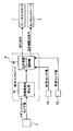
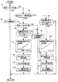
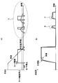
- FIG. 1 is a brake system diagram illustrating a configuration of a hybrid vehicle by front wheel drive to which a brake control device according to a first embodiment is applied. It is a brake fluid pressure circuit diagram showing the VDC brake fluid pressure unit in the brake control device of Example 1. It is a control block diagram which shows the regeneration cooperation brake control system in the brake control apparatus of Example 1. It is a flowchart which shows the structure and flow of a regeneration cooperation brake control process performed with the integrated controller in the brake control apparatus of Example 1.
- FIG. FIG. 5 is a deceleration characteristic diagram showing a relationship of deceleration with respect to driver input when a driver requested deceleration is obtained by a negative pressure booster during a brake operation.
- FIG. 1 is a brake system diagram illustrating a configuration of a hybrid vehicle by front wheel drive to which a brake control device according to a first embodiment is applied. It is a brake fluid pressure circuit diagram showing the VDC brake fluid pressure unit in the brake control device of Example 1. It is a control block diagram which shows the regeneration cooperation brake control
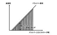
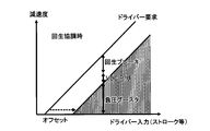
- FIG. 6 is a deceleration characteristic diagram showing a relationship of deceleration with respect to driver input when an offset gap is set based on driver requested deceleration so that a basic hydraulic pressure is generated by a negative pressure booster during brake operation.
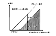
- FIG. 5 is a deceleration characteristic diagram showing a relationship of deceleration with respect to driver input when generating a maximum regenerative torque that compensates a driver requested deceleration by a negative pressure booster and a regenerative brake during a brake operation.
- FIG. 6 is a deceleration characteristic diagram showing a relationship of deceleration with respect to driver input during regenerative coordination in which a driver-requested deceleration is compensated by a negative pressure booster, a regenerative brake, and a VDC brake hydraulic pressure unit during brake operation.
- Vehicle speed, motor drive / stop characteristics (a), deceleration target value, and deceleration when a vehicle equipped with a brake control device of a comparative example is operated with a slow brake as the vehicle shifts from a stopped state to an extremely low vehicle speed 6 is a time chart showing each characteristic (b) of an actual value.
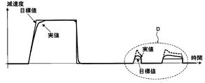
- FIG. 4 is a time chart showing characteristics of a deceleration target value and a deceleration actual value when a hybrid vehicle equipped with the brake control device of the first embodiment performs a slow braking operation as the vehicle shifts from a stopped state to an extremely low vehicle speed. .
- FIG. 1 shows a configuration of a front-wheel drive hybrid vehicle (an example of an electric vehicle) to which the brake control device of the first embodiment is applied
- FIG. 2 shows a VDC brake hydraulic unit (an example of a brake hydraulic actuator).
- the brake system configuration will be described with reference to FIGS. 1 and 2.
- the brake deceleration generation system of the brake control device of the first embodiment includes a brake fluid pressure generating device 1, a VDC brake fluid pressure unit 2 (brake fluid pressure actuator), a stroke sensor 3, and a left sensor.
- a front wheel wheel cylinder 4FL, a right front wheel wheel cylinder 4FR, a left rear wheel wheel cylinder 4RL, a right rear wheel wheel cylinder 4RR, and an electric motor 5 for traveling are provided.
- the brake deceleration generation system of the first embodiment is a regenerative cooperative brake system having a configuration using an existing VDC system (VDC is an abbreviation of “Vehicle Dynamics Control”) mounted on an actual vehicle (engine vehicle).
- VDC vehicle behavior control
- VDC control vehicle behavior control
- the vehicle posture is detected by a sensor.For example, if it is judged as oversteer, the front wheel outside the corner is braked. Conversely, if it is judged as understeer, the driving power is reduced and the tire inside the corner of the rear wheel. To brake.
- the brake fluid pressure generating device 1 is a basic fluid pressure generating means for generating a basic fluid pressure according to a brake operation by a driver.
- the brake fluid pressure generating device 1 includes a brake pedal 11, a negative pressure booster 12, a master cylinder 13, and a reserve tank 14. That is, the driver's brake pedal force applied to the brake pedal 11 is boosted by the negative pressure booster 12, and the primary hydraulic pressure and the secondary hydraulic pressure by the master cylinder pressure are generated by the master cylinder 13. At this time, the deceleration generated by the master cylinder pressure is designed to be smaller than the driver's required deceleration.
- the VDC brake fluid pressure unit 2 is interposed between the brake fluid pressure generator 1 and the wheel cylinders 4FL, 4FR, 4RL, 4RR of each wheel.
- the VDC brake hydraulic pressure unit 2 includes hydraulic pumps 22 and 22 driven by a VDC motor 21 (pump motor), and is a brake hydraulic pressure actuator that controls increase / hold / depressurization of the master cylinder pressure.
- the VDC brake fluid pressure unit 2 and the brake fluid pressure generator 1 are connected by a primary fluid pressure pipe 61 and a secondary fluid pressure pipe 62.
- the VDC brake hydraulic unit 2 and the wheel cylinders 4FL, 4FR, 4RL, 4RR of each wheel are connected by a left front wheel hydraulic pipe 63, a right front wheel hydraulic pipe 64, a left rear wheel hydraulic pipe 65, and a right rear wheel hydraulic pipe 66. ing. That is, at the time of brake operation, the master cylinder pressure generated by the brake fluid pressure generator 1 is pressurized by the VDC brake fluid pressure unit 2 and applied to the wheel cylinders 4FL, 4FR, 4RL, 4RR of each wheel to provide the hydraulic braking force. Trying to get.
- the specific configuration of the VDC brake hydraulic unit 2 includes a VDC motor 21, hydraulic pumps 22 and 22 driven by the VDC motor 21, reservoirs 23 and 23, and a master cylinder pressure sensor 24. And having.
- a first M / C cut solenoid valve 25 differential pressure valve
- a second M / C cut solenoid valve 26 differential pressure valve
- the first M / C cut solenoid valve 25 and the second M / C cut solenoid valve 26 control the differential pressure between the wheel cylinder pressure (downstream pressure) and the master cylinder pressure (upstream pressure) when the VDC motor 21 is operated.
- the stroke sensor 3 is means for detecting a brake pedal operation amount by a driver.
- This stroke sensor 3 is a component added to an existing VDC system as a configuration for detecting a target deceleration, which is necessary information for regenerative cooperative brake control.
- the wheel cylinders 4FL, 4FR, 4RL, and 4RR are set on the front and rear brake discs, and the hydraulic pressure from the VDC brake hydraulic unit 2 is applied. Then, when hydraulic pressure is applied to each wheel cylinder 4FL, 4FR, 4RL, 4RR, a hydraulic braking force is applied to the front and rear wheels by clamping the brake disc with a brake pad.
- the travel electric motor 5 is provided as a travel drive source for the left and right front wheels (drive wheels) and has a drive motor function and a power generator function.
- the electric motor 5 for traveling transmits driving force to the left and right front wheels by driving the motor while consuming battery power during power running. During regeneration, the load is applied to the rotational drive of the left and right front wheels to convert it into electrical energy, and the generated power is charged to the battery. That is, the load applied to the rotational drive of the left and right front wheels is the regenerative braking force.
- the driving system for the left and right front wheels (drive wheels) provided with the traveling electric motor 5 is provided with an engine 10 as a traveling drive source in addition to the traveling electric motor 5, and is driven to the left and right front wheels via the transmission 11. Transmit power.
- the brake deceleration control system of the brake control device includes a brake controller 7, a motor controller 8 (regenerative braking force control means), an integrated controller 9, and an engine controller 12. I have.
- the brake controller 7 inputs the hydraulic pressure command from the integrated controller 9 and the pressure information from the master cylinder pressure sensor 24 of the VDC brake hydraulic pressure unit 2 during regenerative cooperative brake control. Then, a drive command is output to the VDC motor 21 and solenoid valves 25, 26, 27, 28 of the VDC brake hydraulic unit 2 according to a predetermined control law. The brake controller 7 performs the VDC control, TCS control, ABS control, etc. in addition to the regenerative cooperative brake control.
- the motor controller 8 is connected to a traveling electric motor 5 connected to left and right front wheels, which are drive wheels, via an inverter 13, and when a regenerative braking force command is input from the integrated controller 9 during regenerative cooperative brake control, the motor controller 8 It is a regenerative braking force control means for controlling the regenerative braking force generated by the electric motor 5 in accordance with an input command.
- the motor controller 8 also has a function of controlling the motor torque and the motor rotation speed generated by the traveling electric motor 5 according to the traveling state and the vehicle state during traveling.
- the integrated controller 9 achieves the target deceleration by the sum of the basic hydraulic pressure by the master cylinder pressure and the regeneration by the regenerative braking force when braking, and pressurizes the insufficient regeneration by the VDC brake hydraulic unit 2 Perform regenerative cooperative brake control that compensates for the minute.
- the integrated controller 9 includes battery charge capacity information from the battery controller 91, vehicle speed information from the vehicle speed sensor 92, brake operation information from the brake switch 93, brake pedal operation amount information from the stroke sensor 3, and master cylinder pressure sensor 24. Master cylinder pressure information, etc. are input.
- wheel speed rotation number detecting means capable of detecting a vehicle speed up to an extremely low vehicle speed range is used.
- FIG. 3 shows a regenerative cooperative brake control system in the brake control device of the first embodiment.
- the basic configuration of the regenerative cooperative brake control will be described based on FIG.
- the regenerative cooperative brake control system according to the first embodiment includes a brake controller 7, a motor controller 8, and an integrated controller 9.
- the integrated controller 9 includes a target deceleration calculation unit 9a and a regenerative cooperative brake control unit 9b.
- the target deceleration calculation unit 9 a calculates the target deceleration based on the pedal stroke sensor value from the stroke sensor 3.
- the regenerative cooperative brake control unit 9b receives the target deceleration from the target deceleration calculation unit 9a, the MC pressure sensor value from the master cylinder pressure sensor 24, and the vehicle speed sensor value from the vehicle speed sensor 92. Then, the basic hydraulic pressure is determined based on the MC pressure sensor value, the regenerative component and the pressurized component are determined based on the vehicle speed sensor value, and the target deceleration is the sum of basic hydraulic pressure component + regenerative component + pressurized component. Perform the regenerative cooperative brake control calculation to achieve. In accordance with this calculation result, a hydraulic pressure command corresponding to the pressurization is output to the brake controller 7 and a regenerative braking force command corresponding to the regenerative is output to the motor controller 8.
- FIG. 4 is a flowchart showing the configuration and flow of regenerative cooperative brake control processing executed by the integrated controller 8 in the brake control device of the first embodiment (regenerative cooperative brake control means). Hereinafter, each step of FIG. 4 will be described.
- step S1 it is determined whether or not the vehicle speed V is less than a first predetermined value (first predetermined vehicle speed). If YES (vehicle speed V ⁇ first predetermined value), the process proceeds to step S2, and if NO (vehicle speed V ⁇ first predetermined value), the process proceeds to step S3.
- the “first predetermined value (first predetermined vehicle speed)” is set to a value in the extremely low vehicle speed range immediately before the vehicle stops.
- step S2 following the determination that the vehicle speed V ⁇ the first predetermined value (first predetermined vehicle speed) in step S1, the motor drive of the VDC motor 21 is stopped and the process proceeds to return.
- step S3 following the determination that vehicle speed V ⁇ first predetermined value (first predetermined vehicle speed) in step S1, the previous motor drive state of the VDC motor 21 is determined. If it is ON (motor drive state), the process proceeds to step S11. If it is OFF (motor stop state), the process proceeds to step S4.
- step S4 following the determination that the motor is stopped (OFF) in step S3, it is determined whether or not the vehicle speed V exceeds a second predetermined value (second predetermined vehicle speed). If YES (vehicle speed V> second predetermined value), the process proceeds to step S6. If NO (vehicle speed V ⁇ second predetermined value), the process proceeds to step S5.
- the “second predetermined value (second predetermined vehicle speed)” has a relationship of first predetermined value (first predetermined vehicle speed) ⁇ second predetermined value (second predetermined vehicle speed), and the first predetermined value used in step S1. A value larger than a predetermined value (first predetermined vehicle speed) is used. The reason why the two values are made different is to prevent ON / OFF hunting of the DC motor 21.
- step S7 following the determination that the pedal stroke sensor value> 0 in step S6, it corresponds to the brake pedal stroke based on the brake pedal stroke and the first target deceleration rate calculation map (described in the frame of step S7).
- the target deceleration is calculated and the process proceeds to step S8.
- the first target deceleration calculation map is a region characteristic in which the brake pedal stroke is equal to or less than a predetermined value in the map characteristics of stroke-target deceleration, and the vehicle speed V is equal to or higher than a first predetermined value (first predetermined vehicle speed).
- the characteristic is set lower than the map characteristic of the second target deceleration rate calculation map (described in the frame of step S12) used sometimes.
- the amount of reduction in the target deceleration is at least the actual deceleration due to the over-rotation of the VDC motor 21 from the value according to the second target deceleration calculation map (described in the frame of step S12) for obtaining the target deceleration requested by the driver. Is set to a value obtained by subtracting the amount of overshoot.
- step S8 following the calculation of the target deceleration in step S7, the basic hydraulic pressure component is determined based on the MC pressure sensor value, the regeneration component and the pressurization component are determined based on the vehicle speed sensor value, A regenerative cooperative brake control calculation that is achieved by the sum of basic hydraulic pressure + regeneration + pressurization is performed, and the process proceeds to step S9.
- step S9 following the regenerative cooperative brake control calculation in step S8, the hydraulic pressure command value corresponding to the pressurization is determined, and the hydraulic pressure command for obtaining the hydraulic pressure command value is output to the brake controller 7, and the process proceeds to step S10. move on.
- a regenerative braking force command value corresponding to the regenerative component is determined, and a regenerative braking force command for obtaining a regenerative braking force command value is output to the motor controller 8.
- step S10 following the determination of the hydraulic pressure command value in step S9, the motor drive of the VDC motor 21 is restarted, the necessary deceleration is generated by the basic hydraulic pressure, the regenerative component, and the pressurized component, and the process proceeds to return.
- step S12 following the determination that the pedal stroke sensor value> 0 in step S11, the brake pedal stroke is handled based on the brake pedal stroke and the second target deceleration calculation map (described in the frame of step S12).
- the target deceleration is calculated and the process proceeds to step S13.
- the second target deceleration calculation map is set to the target deceleration map characteristic that obtains the target deceleration by setting the deceleration that appears in the driver's brake pedal operation, that is, the driver's required deceleration as the target deceleration. ing.
- step S13 following the calculation of the target deceleration in step S12, the basic hydraulic pressure component is determined based on the MC pressure sensor value, the regeneration component and the pressurization component are determined based on the vehicle speed sensor value, Regenerative cooperative brake control calculation achieved by the sum of basic hydraulic pressure + regeneration + pressurization is performed, and the process proceeds to step S14.
- step S14 following the regenerative cooperative brake control calculation in step S13, a hydraulic pressure command value corresponding to the pressurization is determined, and a hydraulic pressure command for obtaining the hydraulic pressure command value is output to the brake controller 7, and the flow proceeds to step S15. move on.
- a regenerative braking force command value corresponding to the regenerative component is determined, and a regenerative braking force command for obtaining a regenerative braking force command value is output to the motor controller 8.
- step S15 following the determination of the hydraulic pressure command value in step S14, the VDC motor 21 is driven, the necessary deceleration is generated by the basic hydraulic pressure component, the regenerative component, and the pressurized component, and the process proceeds to return.
- Regenerative cooperative braking system using VDC Regenerative coordinated brake control using VDC is the amount of fluid pressure that cannot be compensated for by the VDC brake fluid pressure unit when the scene that cannot be compensated for by the basic fluid pressure and the regenerative component only with respect to the driver's required deceleration. This is the control that achieves the driver's required deceleration by pressurizing.
- a regenerative cooperative brake system using VDC for performing this regenerative cooperative brake control will be described with reference to FIGS.
- a deceleration requested by the driver is obtained by a basic hydraulic pressure component by a negative pressure booster during brake operation.
- the basic hydraulic pressure by the negative pressure booster during braking is offset from the driver requested deceleration so that the deceleration gap is set so that the driver requested deceleration is not reached. To do.
- the deceleration gap is insufficient with respect to the deceleration requested by the driver. Therefore, as shown in FIG. 7, when the maximum regenerative torque is generated, the deceleration requested by the driver is compensated by a negative pressure booster (basic hydraulic pressure component) and a regenerative brake (regenerative component).
- the deceleration requested by the driver may not be compensated for by the regeneration alone. Therefore, as shown in FIG. 8, the deceleration requested by the driver is compensated by a negative pressure booster (basic hydraulic pressure component), a regenerative brake (regenerative component), and a VDC brake hydraulic unit (pressurized component).
- a negative pressure booster basic hydraulic pressure component
- a regenerative brake regenerative component
- VDC brake hydraulic unit pressurized component
- an inexpensive regenerative cooperative brake system using VDC can be configured by simply changing the characteristics of the negative pressure booster, the characteristics of the VDC brake hydraulic unit, and adding a stroke sensor to the existing conventional VDC. Can do. That is, the safety function of the conventional VDC is expanded (safety function + regenerative cooperation function).
- step S1 Regenerative cooperative brake control action when vehicle speed V ⁇ first predetermined value (first predetermined vehicle speed)
- vehicle speed V is equal to or higher than the first predetermined value (first predetermined vehicle speed)
- step S11 is satisfied
- step S3 The process of step S3 ⁇ step S11 ⁇ step S12 ⁇ step S13 ⁇ step S14 ⁇ step S15 ⁇ return is repeated.
- step S12 the target deceleration corresponding to the brake pedal stroke is calculated based on the brake pedal stroke and the second target deceleration calculation map (described in the frame of step S12).
- step S13 the basic hydraulic pressure component is determined based on the MC pressure sensor value, the regeneration component and the pressurization component are determined based on the vehicle speed sensor value, and the target deceleration is determined as the basic hydraulic pressure component + regeneration component + pressurization. Regenerative cooperative brake control calculation that is achieved with the sum of minutes is performed.
- step S ⁇ b> 14 a hydraulic pressure command value corresponding to the pressurization is determined, and a hydraulic pressure command for obtaining the hydraulic pressure command value is output to the brake controller 7.
- a regenerative braking force command value corresponding to the regenerative component is determined, and a regenerative braking force command for obtaining the regenerative braking force command value is output to the motor controller 8.
- the VDC motor 21 is driven, and regenerative cooperative brake control is performed in which the necessary deceleration is generated by the basic hydraulic pressure component, the regenerative component, and the pressurized component.
- step S1 the vehicle speed V becomes lower than the first predetermined value (first predetermined vehicle speed)
- step S2 the VDC motor 21 is stopped in step S2.
- step S4 vehicle speed V> second predetermined value
- step S1 vehicle speed condition in step S4 (vehicle speed V> second predetermined value) is satisfied, as long as the brake operation condition in step S6 is not satisfied, in the flowchart of FIG. 4, step S1 ⁇ step S3 ⁇ step S4 ⁇ step S6 The flow of going from step S5 to return is repeated, and the drive stop state of the VDC motor 21 is maintained.
- the VDC motor 21 operated simultaneously with the brake operation is stopped when the vehicle speed V becomes lower than the first predetermined value (first predetermined vehicle speed). For this reason, the operating frequency and operating time of the VDC motor 21 can be reduced, and the durability reliability of the VDC motor 21 can be improved.
- step S4 Vehicle speed condition (vehicle speed V> second predetermined value) in step S4 and the brake operation condition in step S6 are satisfied.
- the process proceeds from S1, step S3, step S4, step S6, step S7, step S8, step S9, and step S10.
- step S7 the target deceleration corresponding to the brake pedal stroke is calculated based on the brake pedal stroke and the first target deceleration calculation map (described in the frame of step S7).
- step S8 the basic hydraulic pressure is determined based on the MC pressure sensor value, the regenerative component and the pressurized component are determined based on the vehicle speed sensor value, and the target deceleration is determined as the basic hydraulic pressure component + regenerative component + pressurized component.
- the regenerative cooperative brake control calculation achieved with the sum of In step S ⁇ b> 9 a hydraulic pressure command value corresponding to the pressurization amount is determined, and a hydraulic pressure command for obtaining the hydraulic pressure command value is output to the brake controller 7.
- step S10 the motor drive of the VDC motor 21 is resumed, and regenerative cooperative brake control is performed to generate the necessary deceleration by the basic hydraulic pressure, the regenerative component, and the pressurized component.
- a brake control device that has only one map as a target deceleration setting map and sets a normal target deceleration required by the driver bar even in a slow brake operation scene with motor restart. Let it be a comparative example. Then, a comparative operation when a vehicle equipped with the brake control device of the comparative example and a hybrid vehicle equipped with the brake control device of the first embodiment encounter the following slow brake operation scene with the same motor restart will be described. To do.
- the slow brake operation scene refers to the start of the brake operation at time t1 and the operation of the pump motor as shown in FIG. Then, the operation of the pump motor is stopped at time t2 when the vehicle speed reaches a predetermined value, and the vehicle stops at time t3 immediately after that. Then, at time t4 after stopping the pump motor operation, the brake motor is operated at a very low speed due to creep torque or the like, and at time t5, the gentle brake operation is performed and the pump motor is operated. Then, the operation of the pump motor is stopped at time t6 when the vehicle speed reaches a predetermined value.
- the brake motor is operated at a very low speed due to creep torque or the like, and at time t8, a gentle brake operation is performed and the pump motor is operated.
- Example 1 As shown in the time domain characteristics indicated by the arrow A in FIG. 9A, the slow braking operation is performed at the time t5 and the time t8, and the stopped VDC motor 21 is restored.
- the target deceleration value is set to a value lower than the target deceleration value requested by the driver as shown in FIG.
- the deceleration sharing ratio due to the pressurized hydraulic pressure is lowered, and the target rotational speed of the VDC motor 21 is kept low. That is, the basic hydraulic pressure in the slow brake operation region is almost zero (see FIG. 8).
- the pressurization is obtained by controlling the differential pressure valves (first M / C cut solenoid valve 25, second M / C cut solenoid valve 26) and pumping up by the hydraulic pumps 22 and 22. For this reason, when the pressurization amount is lowered, the pump-up boosting width is reduced, and the target rotational speed of the VDC motor 21 for driving the hydraulic pumps 22 and 22 is kept low.
- the occurrence of deceleration overshoot in which the deceleration (actual value) rapidly increases due to the transient overspeed of the VDC motor 21 is prevented as shown by the time domain characteristics of the arrow D in FIG.
- the actual deceleration value of the vehicle can be equivalent to the target deceleration required by the driver (the deceleration target value in FIG. 9B).
- the amount of decrease in the target deceleration is set to a value obtained by subtracting at least the amount of overshoot of the actual deceleration due to over-rotation of the VDC motor 21 from the target deceleration value requested by the driver.
- the actual deceleration value when the motor is restarted substantially matches the desired deceleration target value by setting the target deceleration reduction range in consideration of the actual deceleration due to motor rotation overshoot. Become. Therefore, the ease of handling of the brake feeling is enhanced, such as suppressing the feeling of braking while generating the vehicle deceleration expected by the driver bar.
- the target deceleration value is determined by the first target deceleration calculation map using the brake pedal stroke as a parameter.
- the region characteristic in which the brake pedal stroke is a predetermined value or less is obtained.
- the vehicle speed V is set to a characteristic lower than the characteristic of the second target deceleration calculation map used when the vehicle speed V is equal to or higher than the first predetermined value (first predetermined value).
- the target deceleration is set with the characteristic that the volume is lowered during the slow braking operation
- the target deceleration is set with the characteristic that represents the required deceleration of the driver bar during the sudden braking operation. Therefore, at the time of restarting the motor, it is possible to achieve both suppression of the cuckling brake feeling with respect to the slow braking operation and ensuring the response of the requested deceleration with respect to the sudden braking operation.
- a master cylinder 13 that generates a master cylinder pressure corresponding to the brake operation
- Wheel cylinders 4FL, 4FR, 4RL, 4RR which are provided on each of the front and rear wheels and apply a hydraulic braking force to each wheel according to the wheel cylinder pressure
- Hydraulic pumps 22 and 22 that are interposed between the master cylinder 13 and the wheel cylinders 4FL, 4FR, 4RL, and 4RR and are driven by a pump motor (VDC motor 21), and the pump motor (VDC motor 21).
- VDC brake Brake hydraulic actuator having differential pressure valves (first M / C cut solenoid valve 25, second M / C cut solenoid valve 26) for controlling the differential pressure between the wheel cylinder pressure and the master cylinder pressure Hydraulic unit 2), Regenerative braking force control means (motor controller 8) connected to the driving electric motor 5 connected to the drive wheel and controlling the regenerative braking force generated by the driving electric motor 5;
- Regenerative cooperative brake control means integrated controller 9, FIG.
- step S1 that performs control to compensate for the pressure applied by Motor stop control means (step S1 ⁇ step S2 in FIG. 4) for stopping the pump motor (VDC motor 21) in a driving state when the vehicle speed V becomes lower than a first predetermined vehicle speed (first predetermined value);
- the pump motor (VDC motor 21) is stopped (OFF in step S3), the vehicle speed V exceeds the second predetermined vehicle speed (second predetermined value) (YES in step S4), and a brake operation is performed. If this is the case (YES in step S6), the target deceleration value is set to a value lower than the target deceleration value requested by the driver (step S7), and the pump motor (VDC motor 21) is restarted.
- Motor restart control means (steps S4 to S10 in FIG. 4); Is provided. For this reason, when restarting the pump motor (VDC motor 21) that has been stopped to generate a braking force, it is possible to suppress the cuckling brake feeling and to make the brake feeling easy to handle.
- the motor restart control means requests the target deceleration value from the driver when the vehicle speed V is equal to or higher than the first predetermined vehicle speed (first predetermined value).
- the value is set to a value obtained by subtracting at least the amount of overshoot of the actual deceleration due to over-rotation of the pump motor (VDC motor 21) from the target deceleration value to be performed (step S7). For this reason, in addition to the effect of (1), it is possible to improve the ease of handling of the brake feeling, such as suppressing the feeling of cuckling brakes while generating the vehicle deceleration expected by the driver.
- the motor restarting control means uses the target deceleration map (first deceleration map) with the target deceleration value as a parameter and the brake pedal operation amount (brake pedal stroke).
- a target deceleration calculation map), and in the target deceleration map (first target deceleration calculation map), the brake pedal operation amount (brake pedal stroke) has a region characteristic that is equal to or less than a predetermined value, and the vehicle speed V is a first predetermined value.
- the characteristic was set to be lower than the characteristic of the target deceleration map (second target deceleration calculation map) used when the vehicle speed (first predetermined value) or higher (step S7).
- Example 1 As mentioned above, although the brake control apparatus of the electric vehicle of this invention has been demonstrated based on Example 1, it is not restricted to this Example 1 about a concrete structure, It concerns on each claim of a claim Design changes and additions are allowed without departing from the scope of the invention.
- the second predetermined value (second predetermined vehicle speed) in step S4 is set to a value larger than the first predetermined value (first predetermined vehicle speed) used in step S1, and ON / OFF hunting of the VDC motor 21 is performed.
- An example to prevent is shown.
- the same value may be used for the first predetermined value (first predetermined vehicle speed) and the second predetermined value (second predetermined vehicle speed).
- the motor restart control is also established as a relationship of the first predetermined value (first predetermined vehicle speed)> the second predetermined value (second predetermined vehicle speed).
- the target deceleration is set using the target deceleration calculation map when the stopped VDC motor 21 is restarted to generate the braking force.
- the stopped pump motor is restarted by a calculation process in which a predetermined correction amount is subtracted from the target deceleration obtained from the normal target deceleration map.
- An example of calculating the target deceleration when starting and generating the braking force may be used.
- Example 1 shows an example in which the VDC motor 21 is turned on simultaneously with the brake operation, and the VDC motor 21 is turned off when the vehicle is in a stop area.
- an example of performing motor ON / OFF control that turns off the VDC motor in an area where no pressurization is required among all the deceleration areas due to the brake operation may be used.
- Example 1 shows an example in which the VDC brake hydraulic unit 2 shown in FIG. 2 is used as a brake hydraulic actuator.
- any brake hydraulic actuator may be used as long as it has a hydraulic pump driven by a VDC motor and a differential pressure valve that controls the differential pressure between the wheel cylinder pressure and the master cylinder pressure when the pump motor is operated. .
- Example 1 shows an example in which the brake control device of the present invention is applied to a front-wheel drive hybrid vehicle.
- the vehicle is an electric vehicle such as a rear-wheel drive hybrid vehicle, an electric vehicle, a fuel cell vehicle, etc. and performs regenerative cooperative brake control using a hydraulic braking force and a regenerative braking force
- the brake control device of the present invention is applied. can do.
Landscapes
- Engineering & Computer Science (AREA)
- Transportation (AREA)
- Mechanical Engineering (AREA)
- Physics & Mathematics (AREA)
- Fluid Mechanics (AREA)
- Chemical & Material Sciences (AREA)
- Combustion & Propulsion (AREA)
- Automation & Control Theory (AREA)
- Regulating Braking Force (AREA)
- Electric Propulsion And Braking For Vehicles (AREA)
- Braking Systems And Boosters (AREA)
Abstract
Description
前記マスターシリンダは、ブレーキ操作に応じたマスターシリンダ圧を発生する。
前記ホイールシリンダは、前後輪の各輪に設けられ、ホイールシリンダ圧に応じて各輪に液圧制動力を与える。
前記ブレーキ液圧アクチュエータは、前記マスターシリンダと前記ホイールシリンダとの間に介装され、ポンプ用モータにより駆動する液圧ポンプと、前記ポンプ用モータの作動時、ホイールシリンダ圧とマスターシリンダ圧の差圧を制御する差圧弁と、を有する。
前記回生制動力制御手段は、駆動輪に連結された走行用電動モータに接続され、前記走行用電動モータにより発生する回生制動力を制御する。
前記回生協調ブレーキ制御手段は、ブレーキ操作時、目標減速度を、前記マスターシリンダ圧による基本液圧分と前記回生制動力による回生分の総和で達成し、不足する回生分を前記ブレーキ液圧アクチュエータによる加圧分で補償する制御を行う。
前記モータ停止制御手段は、駆動状態の前記ポンプ用モータを、車速が第1所定車速未満になると停止する。
前記モータ再起動時制御手段は、前記ポンプ用モータが停止状態で、車速が第2所定車速を超え、かつ、ブレーキ操作が行われたとき、前記目標減速度の値を、ドライバーが要求する目標減速度の値よりも低い値に設定し、前記ポンプ用モータを再起動する。
例えば、ポンプ用モータの作動停止後、再び極低速で進みながら緩ブレーキ操作をすることにより、ポンプ用モータを再起動させるようなシーンの場合、要求液圧が低く、かつ、ポンプ用モータが目標回転数に向けて過渡的に過回転になる。このため、加圧分により発生する実液圧が過渡的にオーバーシュートする。
これに対し、停止したポンプ用モータを再起動させるシーンにおいて、予め目標減速度の値を、ドライバーが要求する目標減速度の値より低い値に設定しておくため、加圧分の液圧による減速度分担比率が下げられ、ポンプ用モータの目標回転数が低く抑えられる。したがって、ポンプ用モータの過渡的な過回転により急増する減速度の発生が防止され、車両の減速度を、ドライバーが要求する目標減速度相当にすることができる。
この結果、停止中のポンプ用モータを再起動して制動力を発生させるとき、カックンブレーキ感を抑制し、扱いやすいブレーキフィーリングにすることができる。
図1は、実施例1のブレーキ制御装置を適用した前輪駆動によるハイブリッド車(電動車両の一例)の構成を示し、図2は、VDCブレーキ液圧ユニット(ブレーキ液圧アクチュエータの一例)を示す。以下、図1および図2に基づきブレーキシステム構成を説明する。
この走行用電動モータ5が設けられる左右前輪(駆動輪)の駆動系には、走行用電動モータ5以外に、走行用駆動源としてエンジン10が設けられ、変速機11を介して左右前輪へ駆動力を伝達する。
実施例1の回生協調ブレーキ制御系は、図3に示すように、ブレーキコントローラ7と、モータコントローラ8と、統合コントローラ9と、を備えている。
ここで、「第1所定値(第1所定車速)」は、車両が停止する直前の極低車速域の値に設定される。
ここで、「第2所定値(第2所定車速)」は、第1所定値(第1所定車速)<第2所定値(第2所定車速)という関係にあり、ステップS1で用いた第1所定値(第1所定車速)よりも大きな値を用いている。このように両者の値を異ならせているのは、DCモータ21のON/OFFハンチングを防止するためである。
ここで、第1目標減速度算出マップは、ストローク-目標減速度のマップ特性のうち、ブレーキペダルストロークが所定値以下の領域特性を、車速Vが第1所定値(第1所定車速)以上のときに用いる第2目標減速度算出マップ(ステップS12の枠内記載)のマップ特性よりも嵩下げした特性に設定している。このとき、目標減速度の下げ幅は、ドライバーが要求する目標減速度を得る第2目標減速度算出マップ(ステップS12の枠内記載)による値から、少なくともVDCモータ21の過回転による実減速度のオーバーシュート分を差し引いた値に設定している。
このとき、回生分がある場合には、回生分に対応する回生制動力指令値を決定し、回生制動力指令値を得る回生制動力指令をモータコントローラ8に出力する。
ここで、第2目標減速度算出マップは、ドライバーのブレーキペダル操作にあらわれた減速度、つまり、ドライバーの要求減速度を目標減速度とし、この目標減速度を得る目標減速度マップ特性に設定している。
このとき、回生分がある場合には、回生分に対応する回生制動力指令値を決定し、回生制動力指令値を得る回生制動力指令をモータコントローラ8に出力する。
まず、「VDCを利用した回生協調ブレーキシステムについて」の説明を行う。続いて、実施例1のハイブリッド車のブレーキ制御装置における作用を、「車速V≧第1所定値(第1所定車速)のときの回生協調ブレーキ制御作用」、「車速V<第1所定値(第1所定車速)のときのモータ停止制御作用」、「モータ再起動を伴うブレーキ操作シーンにおける回生協調ブレーキ制御作用」に分けて説明する。
VDCを利用した回生協調ブレーキ制御は、ドライバーの要求減速度に対し、基本液圧分と回生分だけでは補償しきれないシーンが発生すると、VDCブレーキ液圧ユニットによって補償しきれない分の液圧を加圧し、ドライバーの要求減速度を達成する制御である。
この回生協調ブレーキ制御を行うためのVDCを利用した回生協調ブレーキシステムについて、図5~図8に基づいて説明する。
車速Vが第1所定値(第1所定車速)以上であり、かつ、VDCモータ21がモータ駆動状態で、ステップS11のブレーキ操作条件が成立しているときには、図4のフローチャートにおいて、ステップS1→ステップS3→ステップS11→ステップS12→ステップS13→ステップS14→ステップS15→リターンへと進む流れが繰り返される。
車速Vが第1所定値(第1所定車速)未満になったときには、図4のフローチャートにおいて、ステップS1→ステップS2へと進み、ステップS2にて、VDCモータ21が駆動停止される。そして、VDCモータ21が駆動停止状態になると、車速Vが第1所定値(第1所定車速)以上になり、かつ、ステップS4の車速条件(車速V>第2所定値)が成立しない限り、図4のフローチャートにおいて、ステップS1→ステップS3→ステップS4→ステップS5→リターンへと進む流れが繰り返され、VDCモータ21の駆動停止状態が維持される。また、ステップS4の車速条件(車速V>第2所定値)が成立しても、ステップS6のブレーキ操作条件が成立しない限り、図4のフローチャートにおいて、ステップS1→ステップS3→ステップS4→ステップS6→ステップS5→リターンへと進む流れが繰り返され、VDCモータ21の駆動停止状態が維持される。
VDCモータ21を停止した後、極低車速でブレーキ操作をした場合、ステップS4の車速条件(車速V>第2所定値)とステップS6のブレーキ操作条件が成立すると、図4のフローチャートにおいて、ステップS1→ステップS3→ステップS4→ステップS6→ステップS7→ステップS8→ステップS9→ステップS10へと進む。
すなわち、緩ブレーキ操作領域での基本液圧分は、ほぼゼロとなる(図8参照)。また、極低車速域での回生分は、ほとんど望めない。つまり、目標減速度を低下させると、主に加圧分の液圧による減速度分担比率が下げられることになる。そして、加圧分は、差圧弁(第1M/Cカットソレノイドバルブ25、第2M/Cカットソレノイドバルブ26)のコントロールと、液圧ポンプ22,22によるポンプアップ昇圧により得られる。このため、加圧分が下げられると、ポンプアップ昇圧幅が小さくなり、液圧ポンプ22,22を駆動させるVDCモータ21の目標回転数が低く抑えられる。
すなわち、モータ回転オーバーシュートによる実減速度の発生を考慮した目標減速度の下げ幅設定により、モータ再起動時における減速度の実値が、本来あるべき減速度の目標値にほぼ一致することになる。
したがって、ドラーバーが期待する車両減速度を発生しながら、カックンブレーキ感を抑制するというように、ブレーキフィーリングの扱いやすさが高められる。
すなわち、緩ブレーキ操作のときには、嵩下げした特性にて目標減速度が設定され、急ブレーキ操作のときには、ドラーバーの要求減速度をあらわす特性にて目標減速度が設定されることになる。
したがって、モータ再起動時、緩ブレーキ操作に対するカックンブレーキ感の抑制と、急ブレーキ操作に対する要求減速度の応答性確保と、の両立が図られる。
実施例1のハイブリッド車のブレーキ制御装置にあっては、下記に列挙する効果を得ることができる。
前後輪の各輪に設けられ、ホイールシリンダ圧に応じて各輪に液圧制動力を与えるホイールシリンダ4FL,4FR,4RL,4RRと、
前記マスターシリンダ13と前記ホイールシリンダ4FL,4FR,4RL,4RRとの間に介装され、ポンプ用モータ(VDCモータ21)により駆動する液圧ポンプ22,22と、前記ポンプ用モータ(VDCモータ21)の作動時、ホイールシリンダ圧とマスターシリンダ圧の差圧を制御する差圧弁(第1M/Cカットソレノイドバルブ25、第2M/Cカットソレノイドバルブ26)と、を有するブレーキ液圧アクチュエータ(VDCブレーキ液圧ユニット2)と、
駆動輪に連結された走行用電動モータ5に接続され、前記走行用電動モータ5により発生する回生制動力を制御する回生制動力制御手段(モータコントローラ8)と、
ブレーキ操作時、目標減速度を、前記マスターシリンダ圧による基本液圧分と前記回生制動力による回生分の総和で達成し、不足する回生分を前記ブレーキ液圧アクチュエータ(VDCブレーキ液圧ユニット2)による加圧分で補償する制御を行う回生協調ブレーキ制御手段(統合コントローラ9、図4)と、
駆動状態の前記ポンプ用モータ(VDCモータ21)を、車速Vが第1所定車速(第1所定値)未満になると停止するモータ停止制御手段(図4のステップS1→ステップS2)と、
前記ポンプ用モータ(VDCモータ21)が停止状態で(ステップS3でOFF)、車速Vが第2所定車速(第2所定値)を超え(ステップS4でYES)、かつ、ブレーキ操作が行われたとき(ステップS6でYES)、前記目標減速度の値を、ドライバーが要求する目標減速度の値よりも低い値に設定し(ステップS7)、前記ポンプ用モータ(VDCモータ21)を再起動するモータ再起動時制御手段(図4のステップS4~ステップS10)と、
を備える。
このため、停止中のポンプ用モータ(VDCモータ21)を再起動して制動力を発生させるとき、カックンブレーキ感を抑制し、扱いやすいブレーキフィーリングにすることができる。
このため、上記(1)の効果に加え、ドラーバーが期待する車両減速度を発生しながら、カックンブレーキ感を抑制するというように、ブレーキフィーリングの扱いやすさを高めることができる。
このため、上記(1)または(2)の効果に加え、ポンプ用モータ(VDCモータ21)の再起動時、緩ブレーキ操作に対するカックンブレーキ感の抑制と、急ブレーキ操作に対する要求減速度の応答性確保と、の両立を図ることができる。
Claims (3)
- ブレーキ操作に応じたマスターシリンダ圧を発生するマスターシリンダと、
前後輪の各輪に設けられ、ホイールシリンダ圧に応じて各輪に液圧制動力を与えるホイールシリンダと、
前記マスターシリンダと前記ホイールシリンダとの間に介装され、ポンプ用モータにより駆動する液圧ポンプと、前記ポンプ用モータの作動時、ホイールシリンダ圧とマスターシリンダ圧の差圧を制御する差圧弁と、を有するブレーキ液圧アクチュエータと、
駆動輪に連結された走行用電動モータに接続され、前記走行用電動モータにより発生する回生制動力を制御する回生制動力制御手段と、
ブレーキ操作時、目標減速度を、前記マスターシリンダ圧による基本液圧分と前記回生制動力による回生分の総和で達成し、不足する回生分を前記ブレーキ液圧アクチュエータによる加圧分で補償する制御を行う回生協調ブレーキ制御手段と、
駆動状態の前記ポンプ用モータを、車速が第1所定車速未満になると停止するモータ停止制御手段と、
前記ポンプ用モータが停止状態で、車速が第2所定車速を超え、かつ、ブレーキ操作が行われたとき、前記目標減速度の値を、ドライバーが要求する目標減速度の値よりも低い値に設定し、前記ポンプ用モータを再起動するモータ再起動時制御手段と、
を備えることを特徴とする電動車両のブレーキ制御装置。 - 請求項1に記載された電動車両のブレーキ制御装置において、
前記モータ再起動時制御手段は、前記目標減速度の値を、車速が第1所定車速以上のときのドライバーが要求する目標減速度の値から、少なくとも前記ポンプ用モータの過回転による実減速度のオーバーシュート分を差し引いた値に設定することを特徴とする電動車両のブレーキ制御装置。 - 請求項1または請求項2に記載された電動車両のブレーキ制御装置において、
前記モータ再起動時制御手段は、前記目標減速度の値を、ブレーキペダル操作量をパラメータとする目標減速度マップで決め、該目標減速度マップのうち、ブレーキペダル操作量が所定値以下の領域特性を、車速が第1所定車速以上のときに用いる目標減速度マップの特性よりも嵩下げした特性に設定したことを特徴とする電動車両のブレーキ制御装置。
Priority Applications (4)
| Application Number | Priority Date | Filing Date | Title |
|---|---|---|---|
| JP2012542847A JP5447690B2 (ja) | 2010-11-08 | 2011-09-30 | 電動車両のブレーキ制御装置 |
| US13/820,114 US8998352B2 (en) | 2010-11-08 | 2011-09-30 | Vehicle brake control device for an electrically driven vehicle |
| CN201180053888.XA CN103201146B (zh) | 2010-11-08 | 2011-09-30 | 用于电力驱动车辆的制动控制装置 |
| EP11840515.8A EP2639122B1 (en) | 2010-11-08 | 2011-09-30 | Electric vehicle brake control device |
Applications Claiming Priority (2)
| Application Number | Priority Date | Filing Date | Title |
|---|---|---|---|
| JP2010249877 | 2010-11-08 | ||
| JP2010-249877 | 2010-11-08 |
Publications (1)
| Publication Number | Publication Date |
|---|---|
| WO2012063572A1 true WO2012063572A1 (ja) | 2012-05-18 |
Family
ID=46050726
Family Applications (1)
| Application Number | Title | Priority Date | Filing Date |
|---|---|---|---|
| PCT/JP2011/072601 WO2012063572A1 (ja) | 2010-11-08 | 2011-09-30 | 電動車両のブレーキ制御装置 |
Country Status (5)
| Country | Link |
|---|---|
| US (1) | US8998352B2 (ja) |
| EP (1) | EP2639122B1 (ja) |
| JP (1) | JP5447690B2 (ja) |
| CN (1) | CN103201146B (ja) |
| WO (1) | WO2012063572A1 (ja) |
Cited By (3)
| Publication number | Priority date | Publication date | Assignee | Title |
|---|---|---|---|---|
| JP2015116085A (ja) * | 2013-12-13 | 2015-06-22 | トヨタ自動車株式会社 | 車両制御装置 |
| JP2019127211A (ja) * | 2018-01-26 | 2019-08-01 | 株式会社Subaru | 車両用制御装置 |
| WO2022091879A1 (ja) * | 2020-10-26 | 2022-05-05 | 日立Astemo株式会社 | 車両用ブレーキ装置 |
Families Citing this family (8)
| Publication number | Priority date | Publication date | Assignee | Title |
|---|---|---|---|---|
| CN103354790B (zh) * | 2011-02-09 | 2016-04-06 | 铃木株式会社 | 混合动力车辆的驱动控制设备及混合动力车辆 |
| KR102286743B1 (ko) * | 2014-11-05 | 2021-08-09 | 현대모비스 주식회사 | 차량용 회생제동 시스템 제어 방법 |
| US10011255B2 (en) * | 2014-11-07 | 2018-07-03 | Honda Motor Co., Ltd. | Vehicle brake system and vehicle brake system control method |
| KR101704176B1 (ko) * | 2015-03-23 | 2017-02-07 | 현대자동차주식회사 | 하이브리드 차량의 제동 제어 방법 |
| US10696164B2 (en) | 2017-05-18 | 2020-06-30 | Ford Global Technologies, Llc | Optimizing regenerative braking efficiency in a hybrid vehicle |
| KR102563595B1 (ko) * | 2018-10-05 | 2023-08-03 | 현대자동차주식회사 | 전동식 부스터 타입 제동 시스템의 킥-백 제어 시스템 및 방법 |
| US11498428B2 (en) | 2019-10-28 | 2022-11-15 | Caterpillar Inc. | Directional shift variable brake disengagement |
| JP7172950B2 (ja) * | 2019-10-31 | 2022-11-16 | トヨタ自動車株式会社 | 車両用ブレーキシステム |
Citations (4)
| Publication number | Priority date | Publication date | Assignee | Title |
|---|---|---|---|---|
| JPH0911875A (ja) * | 1995-06-30 | 1997-01-14 | Mitsubishi Motors Corp | 車両の旋回制御装置 |
| JP2000280890A (ja) * | 1999-03-30 | 2000-10-10 | Unisia Jecs Corp | ブレーキ装置 |
| JP2002331925A (ja) * | 2001-05-11 | 2002-11-19 | Toyota Motor Corp | 液圧源装置 |
| JP2006096218A (ja) | 2004-09-30 | 2006-04-13 | Advics:Kk | 車両用ブレーキ装置 |
Family Cites Families (6)
| Publication number | Priority date | Publication date | Assignee | Title |
|---|---|---|---|---|
| JP4296991B2 (ja) * | 2004-06-08 | 2009-07-15 | 株式会社アドヴィックス | 車両用ブレーキ装置 |
| US8366210B2 (en) * | 2006-04-03 | 2013-02-05 | Advics Co., Ltd. | Braking apparatus for vehicle |
| JP4623090B2 (ja) * | 2007-12-25 | 2011-02-02 | トヨタ自動車株式会社 | ブレーキ制御装置 |
| JP5107075B2 (ja) * | 2008-01-31 | 2012-12-26 | トヨタ自動車株式会社 | 制動装置 |
| JP5150410B2 (ja) * | 2008-08-25 | 2013-02-20 | 日立オートモティブシステムズ株式会社 | ブレーキ装置 |
| JP5691453B2 (ja) * | 2010-12-03 | 2015-04-01 | 日産自動車株式会社 | 電動車両のブレーキ制御装置 |
-
2011
- 2011-09-30 US US13/820,114 patent/US8998352B2/en not_active Expired - Fee Related
- 2011-09-30 WO PCT/JP2011/072601 patent/WO2012063572A1/ja active Application Filing
- 2011-09-30 CN CN201180053888.XA patent/CN103201146B/zh not_active Expired - Fee Related
- 2011-09-30 EP EP11840515.8A patent/EP2639122B1/en not_active Not-in-force
- 2011-09-30 JP JP2012542847A patent/JP5447690B2/ja not_active Expired - Fee Related
Patent Citations (4)
| Publication number | Priority date | Publication date | Assignee | Title |
|---|---|---|---|---|
| JPH0911875A (ja) * | 1995-06-30 | 1997-01-14 | Mitsubishi Motors Corp | 車両の旋回制御装置 |
| JP2000280890A (ja) * | 1999-03-30 | 2000-10-10 | Unisia Jecs Corp | ブレーキ装置 |
| JP2002331925A (ja) * | 2001-05-11 | 2002-11-19 | Toyota Motor Corp | 液圧源装置 |
| JP2006096218A (ja) | 2004-09-30 | 2006-04-13 | Advics:Kk | 車両用ブレーキ装置 |
Non-Patent Citations (1)
| Title |
|---|
| See also references of EP2639122A4 |
Cited By (5)
| Publication number | Priority date | Publication date | Assignee | Title |
|---|---|---|---|---|
| JP2015116085A (ja) * | 2013-12-13 | 2015-06-22 | トヨタ自動車株式会社 | 車両制御装置 |
| JP2019127211A (ja) * | 2018-01-26 | 2019-08-01 | 株式会社Subaru | 車両用制御装置 |
| DE102018132271A1 (de) | 2018-01-26 | 2019-08-01 | Subaru Corporation | Fahrzeugsteuervorrichtung |
| US11465509B2 (en) | 2018-01-26 | 2022-10-11 | Subaru Corporation | Vehicle control apparatus |
| WO2022091879A1 (ja) * | 2020-10-26 | 2022-05-05 | 日立Astemo株式会社 | 車両用ブレーキ装置 |
Also Published As
| Publication number | Publication date |
|---|---|
| US8998352B2 (en) | 2015-04-07 |
| CN103201146B (zh) | 2015-07-15 |
| EP2639122B1 (en) | 2017-11-08 |
| US20130154344A1 (en) | 2013-06-20 |
| JP5447690B2 (ja) | 2014-03-19 |
| EP2639122A1 (en) | 2013-09-18 |
| JPWO2012063572A1 (ja) | 2014-05-12 |
| EP2639122A4 (en) | 2015-03-18 |
| CN103201146A (zh) | 2013-07-10 |
Similar Documents
| Publication | Publication Date | Title |
|---|---|---|
| JP5447690B2 (ja) | 電動車両のブレーキ制御装置 | |
| JP5768352B2 (ja) | 電動車両のブレーキ制御装置 | |
| JP5699041B2 (ja) | ブレーキ制御装置 | |
| JP6056340B2 (ja) | 制動制御装置 | |
| JP5270654B2 (ja) | ブレーキ制御装置 | |
| JP5668856B2 (ja) | 車両のブレーキ制御装置 | |
| JP2006311791A (ja) | 車両用ブレーキ制御装置 | |
| JP2015051672A (ja) | ブレーキシステム及びブレーキ装置及びブレーキ制御方法 | |
| JP5797542B2 (ja) | ブレーキ装置 | |
| JP5630130B2 (ja) | 電動車両のブレーキ制御装置 | |
| JP4526342B2 (ja) | 4輪駆動車両の運動制御装置 | |
| JP2013177024A (ja) | 電動車両のブレーキ制御装置 | |
| JP5853573B2 (ja) | 制動力制御装置 | |
| JP2012131306A (ja) | 電動車両のブレーキ制御装置 | |
| JP5853682B2 (ja) | 車両のブレーキ制御装置 | |
| JP2012025389A (ja) | 車両用ブレーキ制御装置 | |
| JP2014080126A (ja) | 車両のブレーキ制御装置 | |
| JP2013032142A (ja) | 車両のブレーキ制御装置 | |
| JP5879974B2 (ja) | 車両のブレーキ制御装置 | |
| JP5889664B2 (ja) | ブレーキ制御装置 | |
| JP5799741B2 (ja) | ブレーキ制御装置 | |
| JP5966662B2 (ja) | 車両のブレーキ制御装置 | |
| JP5683305B2 (ja) | ブレーキ制御装置 | |
| JP5872412B2 (ja) | ブレーキ制御装置 | |
| JP5567791B2 (ja) | 車両の制動力制御装置 |
Legal Events
| Date | Code | Title | Description |
|---|---|---|---|
| 121 | Ep: the epo has been informed by wipo that ep was designated in this application |
Ref document number: 11840515 Country of ref document: EP Kind code of ref document: A1 |
|
| WWE | Wipo information: entry into national phase |
Ref document number: 2012542847 Country of ref document: JP |
|
| REEP | Request for entry into the european phase |
Ref document number: 2011840515 Country of ref document: EP |
|
| WWE | Wipo information: entry into national phase |
Ref document number: 2011840515 Country of ref document: EP |
|
| WWE | Wipo information: entry into national phase |
Ref document number: 13820114 Country of ref document: US |
|
| NENP | Non-entry into the national phase |
Ref country code: DE |