WO2012057239A1 - 係留装置及びそれを用いたステアリング係留機構 - Google Patents
係留装置及びそれを用いたステアリング係留機構 Download PDFInfo
- Publication number
- WO2012057239A1 WO2012057239A1 PCT/JP2011/074740 JP2011074740W WO2012057239A1 WO 2012057239 A1 WO2012057239 A1 WO 2012057239A1 JP 2011074740 W JP2011074740 W JP 2011074740W WO 2012057239 A1 WO2012057239 A1 WO 2012057239A1
- Authority
- WO
- WIPO (PCT)
- Prior art keywords
- mooring
- fixing
- fixed
- mooring device
- members
- Prior art date
- Legal status (The legal status is an assumption and is not a legal conclusion. Google has not performed a legal analysis and makes no representation as to the accuracy of the status listed.)
- Ceased
Links
Images

Classifications
-
- F—MECHANICAL ENGINEERING; LIGHTING; HEATING; WEAPONS; BLASTING
- F16—ENGINEERING ELEMENTS AND UNITS; GENERAL MEASURES FOR PRODUCING AND MAINTAINING EFFECTIVE FUNCTIONING OF MACHINES OR INSTALLATIONS; THERMAL INSULATION IN GENERAL
- F16G—BELTS, CABLES, OR ROPES, PREDOMINANTLY USED FOR DRIVING PURPOSES; CHAINS; FITTINGS PREDOMINANTLY USED THEREFOR
- F16G11/00—Means for fastening cables or ropes to one another or to other objects; Caps or sleeves for fixing on cables or ropes
- F16G11/02—Means for fastening cables or ropes to one another or to other objects; Caps or sleeves for fixing on cables or ropes with parts deformable to grip the cable or cables; Fastening means which engage a sleeve or the like fixed on the cable
- F16G11/025—Fastening means which engage a sleeve or the like fixed on the cable, e.g. caps
-
- B—PERFORMING OPERATIONS; TRANSPORTING
- B62—LAND VEHICLES FOR TRAVELLING OTHERWISE THAN ON RAILS
- B62D—MOTOR VEHICLES; TRAILERS
- B62D1/00—Steering controls, i.e. means for initiating a change of direction of the vehicle
- B62D1/02—Steering controls, i.e. means for initiating a change of direction of the vehicle vehicle-mounted
- B62D1/16—Steering columns
-
- F—MECHANICAL ENGINEERING; LIGHTING; HEATING; WEAPONS; BLASTING
- F16—ENGINEERING ELEMENTS AND UNITS; GENERAL MEASURES FOR PRODUCING AND MAINTAINING EFFECTIVE FUNCTIONING OF MACHINES OR INSTALLATIONS; THERMAL INSULATION IN GENERAL
- F16G—BELTS, CABLES, OR ROPES, PREDOMINANTLY USED FOR DRIVING PURPOSES; CHAINS; FITTINGS PREDOMINANTLY USED THEREFOR
- F16G11/00—Means for fastening cables or ropes to one another or to other objects; Caps or sleeves for fixing on cables or ropes
- F16G11/02—Means for fastening cables or ropes to one another or to other objects; Caps or sleeves for fixing on cables or ropes with parts deformable to grip the cable or cables; Fastening means which engage a sleeve or the like fixed on the cable
-
- Y—GENERAL TAGGING OF NEW TECHNOLOGICAL DEVELOPMENTS; GENERAL TAGGING OF CROSS-SECTIONAL TECHNOLOGIES SPANNING OVER SEVERAL SECTIONS OF THE IPC; TECHNICAL SUBJECTS COVERED BY FORMER USPC CROSS-REFERENCE ART COLLECTIONS [XRACs] AND DIGESTS
- Y10—TECHNICAL SUBJECTS COVERED BY FORMER USPC
- Y10T—TECHNICAL SUBJECTS COVERED BY FORMER US CLASSIFICATION
- Y10T24/00—Buckles, buttons, clasps, etc.
- Y10T24/31—Plural fasteners having intermediate flaccid connector
- Y10T24/318—Strap connector
Definitions
- the present invention relates to a mooring device, and more particularly, to a mooring device for mooring a heavy member that can be energized.
- the present invention also relates to a steering mooring mechanism using the mooring device.
- the two weight members are moored by a mooring device.
- the anchoring device has terminals attached to both ends of the wire, and anchors both terminals by fixing the terminals at one end and the other end to one and the other weight members, respectively.
- Patent Documents 1 to 3 disclose wire ropes or control cables that may be used as the mooring device.
- the wire rope disclosed in Patent Document 1 is attached by caulking a metal round wire terminal to the end of the wire.
- the wire rope is fixed to the weight member by tightening a bolt inserted into the round wire terminal into a screw hole provided in the weight member.
- control cable disclosed in Patent Document 2 has a resin terminal having a spherical recess formed at the end of a wire.
- the control cable is fixed to the weight member by fitting a pin having a spherical portion attached to the weight member into a spherical recess formed in the terminal.
- control cable disclosed in Patent Document 2 uses a resin terminal, the fixing strength of the terminal to the weight member is weakened. Therefore, this control cable is also not suitable for use as a mooring device.
- the present invention has been made in view of the above-described problems, and can easily and firmly connect heavy members to each other, prevent energization, and cause malfunction of electronic components and the like disposed in the vicinity.
- An object of the present invention is to provide a mooring device that does not generate noise and heat.
- an object of the present invention is to provide a steering mooring mechanism using the mooring device.
- the mooring device of the present invention is a mooring device having a fixing member fixed to each of two energized members to be energized and a metal connecting member for connecting the fixing members to each other.
- at least one of the fixing members includes a metal fixing body fixed to the mooring target member, and a connection body made of a non-conducting material that connects the fixing body and the connecting member in a non-contact manner.
- the connecting member is de-energized with the mooring target member on the side where the non-energized fixing member is fixed.
- the fixed body of the non-energizing fixing member fixed to the mooring target member is connected to the connecting member in a non-contact manner by the connecting body, two mooring target members that can be energized are connected. It can be moored in a non-energized state and does not cause noise or heat generation that causes malfunction of electronic components disposed around.
- the mooring device can be firmly fixed to the mooring target member because the fixed body is made of metal.
- the mooring device of the present invention uses a fixed body in which the fixing portion used when fixing to the mooring target member and the support portion connected by the connecting member and the connecting body are separated by the extending portion.
- the fixing portion can be firmly fixed to the mooring target member without being affected by the connection body.
- the support portion of the fixed body covered with the connection body is provided so as to extend in both directions perpendicular to the extension portion, the tensile force applied to the fixed body is distributed to the support portion.
- the fixed body can be prevented from coming off from the connection body.
- the side limbs of the fixed body covered by the connection body are provided so as to extend in parallel with the extending part from the tip of the support part. Can be dispersed in the side limbs to prevent the fixed body from coming off the connecting body.
- the steering mooring mechanism of the present invention can securely moor the vehicle steering operation mechanism and the power steering mechanism, which are two members to be energized, without energizing them. it can.
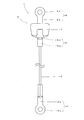
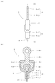
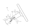
- the top view of the mooring apparatus of this invention (A) Enlarged side view of the non-energized fixing member, (b) AA sectional view of the non-conductive fixing member shown in (a). The schematic side view of a steering mooring mechanism. The enlarged side view of a steering mooring mechanism.
- the mooring device 1 of the present invention includes a connecting member 2, a non-energizing fixing member 3 provided at one end of the connecting member 2, and an energizing fixing member 4 provided at the other end of the connecting member 2. It is comprised by.
- the connecting member 2 is a wire made of a metal such as iron.
- a metal terminal body 5 is attached to one end of the connecting member 2. As shown in FIG. 2 (b), the terminal body 5 is formed in a columnar body portion 5a in an annular shape on an outer peripheral surface of a hole 5b that opens at one end and fixes the connecting member 2.
- the one end of the connecting member 2 is inserted into the hole 5b, the one end of the connecting member 2 is fixed by caulking the main body 5a.
- the first recess 5c is formed in the vicinity of the center in the longitudinal direction of the main body 5a, and its cross-sectional shape is substantially U-shaped.
- the second recess 5d is provided at a substantially middle point between the other end of the main body 5a and the first recess 5c.
- the second concave portion 5d includes a bottom surface parallel to the longitudinal direction of the main body portion 5a, a side surface on one end side of the main body portion 5a inclined toward the first concave portion 5c, and the other end side of the main body portion 5a perpendicular to the bottom surface. And side surfaces.
- the non-energizing fixing member 3 includes a fixing body 6 made of a metal such as iron, and a polyamide that connects the fixing body 6 and the terminal body 5 in a non-contact manner. And a connection body 7 made of a resin material that is hard and non-conductive.
- the fixed body 6 has a flat plate shape, and as shown in FIG. 2B, the other end side is formed in a circular shape and a through hole is formed in the center thereof, and the fixed portion 6a.
- An extension portion 6b extending straight from the extension portion 6b, and support portions 6c and 6d extending straight from the left and right ends of the extension portion 6b in a direction perpendicular to the extension portion 6b, and the support portions 6c and 6d, respectively.
- Side limbs 6e and 6f extending in parallel to the extension 6b are provided on the opposite side of the extension 6b from the respective tips.
- the side surfaces of the side limbs 6e and 6f opposite to each other are inclined and extended so as to gradually approach toward one end side.
- the connecting body 7 is connected to the other end side of the first recess 5c of the terminal body 5, the support portions 6c and 6d of the fixed body 6 and the side limb portions 6e and 6f. Between the limbs 6e and 6f, the other end of the terminal body 5 is connected to the side limbs in a non-contact state by covering with the resin material. In the connecting body 7, the resin material constituting the connecting body 7 also enters the second recess 5 d of the terminal body 5.
- connection body 7 has the terminal material 5 and the fixed body 6 positioned in advance in a molding die outside the drawing as described above, for example, and the resin material before curing in the molding die outside the drawing. Can be formed by injecting and then curing.
- the energization fixing member 4 is made of a flat metal such as iron, and as shown in FIG. 1, one end side is formed in a circular shape, and a fixing portion 4a in which a through hole is formed in the center, A connecting portion 4b that extends straight from the fixing portion 4a to the other end side and has a tip end side formed in a cylindrical shape for inserting the other end of the connecting member 2 is provided. After the other end of the connecting member 2 is inserted into the connecting portion 4b, the other end of the connecting member 2 is fixed by crimping.
- the mooring device 1 configured as described above includes a steering operation mechanism 8 disposed in an automobile (not shown) and power steering as two energized members to be energized. This can be used when the steering mooring mechanism 10 is constructed by mooring the mechanism 9.
- the steering operation mechanism 8 is used to connect a steering wheel 8 a for a driver to operate, and to rotate in conjunction with the steering wheel 8 a and to the power steering mechanism 9. It is configured by a cylindrical connecting portion 8b opened at the tip, and a steering column 8c that houses an interlocking mechanism for interlocking the steering wheel 8a and the connecting portion 8b.
- the steering column 8c is made of a material such as metal that can be energized.
- the steering column 8c is held in an automobile not shown in the drawing while allowing movement in a direction approaching and moving away from the power steering mechanism 9 in order to absorb an impact when an accident occurs.
- the power steering mechanism 9 assists rotation of the steering wheel 8a by the driver, and a control box that houses an assist mechanism for assisting rotation of the steering wheel 8a.
- 9a and a connecting shaft 9b that protrudes from the end of the control box 9a on the steering operation mechanism 8 side and is connected to the connecting portion 8b and rotated together by being inserted into the connecting portion 8b.
- the control box 9a is made of a material that can be energized, such as metal, and is held in a vehicle outside the figure so as not to move.
- the connecting shaft 9b is connected while maintaining non-conductivity, for example, by sandwiching a non-conducting material (not shown) between the connecting portions 8b. Further, the connecting shaft 9b changes the amount of insertion into the connecting portion 8b due to an impact when an unillustrated automobile is involved in an accident or the like, causing the steering operation mechanism 8 to approach and separate from the power steering mechanism 9. Absorbs shock and protects the driver.
- the mooring device 1 is provided with a bolt 11a in which the non-energizing fixing member 3 is inserted into a through hole provided in the fixing portion 6a of the fixing body 6 in the steering column 8c. It is fixed to the steering column 8c by tightening into a screw hole outside the figure. Further, the energization fixing member 4 tightens a bolt 11b inserted through a through hole provided in the fixing portion 4a into a screw hole (not shown) provided in the control box 9a, thereby the control box 9a. Fixed to. The steering mooring mechanism 10 is configured by these fixations.
- the mooring device 1 is deenergized based on the fact that the terminal body 5 and the stationary body 6 are connected by the connection body 7 in a non-contact manner. Therefore, the non-energizing fixing member 3, the connecting member 2, and the energizing fixing member 4 are not energized. Moreover, since the connection member 2 is arrange
- the steering column 8c and the steering wheel 8a are not energized via the mooring device 1, and the connecting portion 8b and the connecting shaft 9b are connected with non-energization as described above. Therefore, the steering operation mechanism 8 and the power steering mechanism 9 are not energized, and problems such as noise, heat generation, malfunctions and failures of surrounding electronic components do not occur.
- the steering column 8c and the control box 9a are connected by bolts 11a and 11b. It can be tightened strongly.
- the fixed body 6 in which the fixed portion 6a fixed to the steering column 8c and the support portions 6c and 6d are separated by the extending portion 6b is used. Therefore, in the mooring device 1, the fixing portion 6 a is fixed to the steering column 8 c by the resin material, and the support portion 6 c, 6 d, etc. are covered so that the influence of the thick connecting body 7 is increased by the fixing portion 6 a. It can be performed firmly in a small space without receiving.
- the terminal material 5 when the terminal material 5 is subjected to a strong tensile force by fitting the resin material constituting the connection body 7 into the second recess 5 d of the terminal body 5, It is possible to prevent the terminal body 5 from coming off the connection body 7.
- the support portions 6 c and 6 d of the fixed body 6 covered with the resin material constituting the connection body 7 extend in the vertical direction with respect to the extension portion 6 b, respectively.
- the tensile force can be distributed to the support portions 6c and 6d. Therefore, it is possible to prevent the fixed body 6 from coming off the connection body 7.
- the side limbs 6e and 6f of the fixed body 6 that is also covered with the resin material that constitutes the connection body 7 extend in parallel to the extending portion 6b, a strong twisting force is applied to the fixed body 6. Can be distributed to the side limbs 6e and 6f. Therefore, it is possible to prevent the fixed body 6 from being detached from the connection body 7.
- the mooring device 1 connects the steering operation mechanism 8 to the power steering mechanism 9 to prevent its falling, so that the driver's safety can be ensured.
- the mooring device 1 and the steering mooring mechanism 10 shown in the present embodiment are only one aspect of the mooring device and the steering mooring mechanism according to the present invention, and various modifications may be made without departing from the gist of the present invention. Is possible.
- the mooring device 1 can be used not only when forming the steering mooring mechanism 10 but also when mooring any two mooring target members.
- the mooring device 1 can be suitably used when the two mooring target members are energizable and heavy, and it is necessary to moor both of them so that they cannot be energized.
- connection member 2 of the mooring device 1 is covered with the non-conductive tube having non-conductive property and flexibility so that the connection member 2 may be brought into contact with the non-conductive fixed member 3 or the steering column 8c. It may not be energized. Moreover, you may ensure non-conducting property by coating the connection member 2 with a non-conducting material instead of a non-conducting tube.
- the mooring apparatus according to the present invention can be used when mooring a mooring target member.
- the steering mooring mechanism according to the present invention can be used as a steering mooring mechanism for mooring a steering operation mechanism and a power steering mechanism in an automobile.
Landscapes
- Engineering & Computer Science (AREA)
- General Engineering & Computer Science (AREA)
- Mechanical Engineering (AREA)
- Chemical & Material Sciences (AREA)
- Combustion & Propulsion (AREA)
- Transportation (AREA)
- Steering Controls (AREA)
- Flexible Shafts (AREA)
Abstract
Description
2 連結部材
3 非通電固定部材
4 通電固定部材
5 端末体
5d 第2凹部
6 固定体
6a 固定部
6b 延出部
6c、6d 支持部
6e、6f 側肢部
7 接続体
8 ステアリング操作機構
9 パワーステアリング機構
10 ステアリング係留機構
Claims (5)
- 2つの通電可能な係留対象部材にそれぞれ固定される固定部材と、該固定部材同士を連結する金属製の連結部材とを有する係留装置であって、
前記固定部材の少なくとも一方は、前記係留対象部材に固定される金属製の固定体と、該固定体と前記連結部材とを非接触に接続する非通電材料製の接続体とを有する非通電固定部材として構成することにより、
前記連結部材は、前記非通電固定部材が固定される側の前記係留対象部材と非通電にされることを特徴とする係留装置。 - 前記固定体は、前記係留対象部材に固定するときに用いられる貫通孔が形成された固定部と、該固定部から前記連結部材側に向かって延びる延出部と、該延出部の前記連結部材側の端部から当該延出部に対して垂直方向両側に延びる支持部とを有し、
前記接続体は前記支持部を覆うことを特徴とする請求項1記載の係留装置。 - 前記固定体は、前記支持部の両端近傍から前記延出部の延びる方向と平行に延び、前記連結部材の端部を間に挟むように設けられた側肢部を有し、
前記接続体は前記側肢部を覆うことを特徴とする請求項2記載の係留装置。 - 前記連結部材の端部には、凹部を有する金属製の端末体が設けられており、
前記接続体は前記端末体の凹部を覆うことを特徴とする請求項1~3の何れかに記載の係留装置。 - 請求項1~4の何れかに記載の係留装置を備え、
前記係留対象部材が、車両のステアリング操作機構と、パワーステアリング機構とであることを特徴とするステアリング係留機構。
Priority Applications (2)
| Application Number | Priority Date | Filing Date | Title |
|---|---|---|---|
| CN201180052358.3A CN103201534B (zh) | 2010-10-28 | 2011-10-27 | 系留装置及使用了该系留装置的转向系留机构 |
| US13/880,433 US9291239B2 (en) | 2010-10-28 | 2011-10-27 | Mooring device and steering mooring mechanism using same |
Applications Claiming Priority (2)
| Application Number | Priority Date | Filing Date | Title |
|---|---|---|---|
| JP2010242458A JP5735255B2 (ja) | 2010-10-28 | 2010-10-28 | 係留装置及びそれを用いたステアリング係留機構 |
| JP2010-242458 | 2010-10-28 |
Publications (1)
| Publication Number | Publication Date |
|---|---|
| WO2012057239A1 true WO2012057239A1 (ja) | 2012-05-03 |
Family
ID=45993944
Family Applications (1)
| Application Number | Title | Priority Date | Filing Date |
|---|---|---|---|
| PCT/JP2011/074740 Ceased WO2012057239A1 (ja) | 2010-10-28 | 2011-10-27 | 係留装置及びそれを用いたステアリング係留機構 |
Country Status (4)
| Country | Link |
|---|---|
| US (1) | US9291239B2 (ja) |
| JP (1) | JP5735255B2 (ja) |
| CN (1) | CN103201534B (ja) |
| WO (1) | WO2012057239A1 (ja) |
Families Citing this family (2)
| Publication number | Priority date | Publication date | Assignee | Title |
|---|---|---|---|---|
| JP2014189188A (ja) * | 2013-03-27 | 2014-10-06 | Showa Corp | ステアリング装置 |
| CN109533366B (zh) * | 2018-11-13 | 2021-04-30 | 中国直升机设计研究所 | 一种双自由度系留装置及其设计方法 |
Citations (4)
| Publication number | Priority date | Publication date | Assignee | Title |
|---|---|---|---|---|
| JPS52163658U (ja) * | 1976-06-04 | 1977-12-12 | ||
| JPH09210140A (ja) * | 1996-01-29 | 1997-08-12 | Tokyo Seiko Co Ltd | ワイヤ・ロープ端末の封止構造 |
| JPH11178182A (ja) * | 1997-12-05 | 1999-07-02 | Hien Electric Industries Ltd | ケーブル吊り下げ用螺旋状支持具とその施工方法 |
| JP2002191115A (ja) * | 2000-12-20 | 2002-07-05 | Yazaki Corp | プーリングアイ |
Family Cites Families (33)
| Publication number | Priority date | Publication date | Assignee | Title |
|---|---|---|---|---|
| US3533302A (en) * | 1969-03-17 | 1970-10-13 | Elmer K Hansen | Apparatus for locking a tiltable steering column in an adjusted position |
| JPS5845167Y2 (ja) * | 1977-10-20 | 1983-10-14 | 株式会社クボタ | オフセット型トラクタ |
| JPS607260Y2 (ja) * | 1979-06-27 | 1985-03-11 | マツダ株式会社 | 自動車用ハンドルの安全装置 |
| US4462606A (en) * | 1981-02-12 | 1984-07-31 | Hon Corporation International | Foldable and portable vehicle |
| SE8206967D0 (sv) * | 1982-12-07 | 1982-12-07 | Riggarna Sundman Larsson & Jos | Vantskruv |
| USRE34359E (en) * | 1987-04-17 | 1993-08-31 | Nippon Seiko Kabushiki Kaisha | Electric steering apparatus |
| JP2685235B2 (ja) | 1988-07-29 | 1997-12-03 | 株式会社東芝 | 薄膜磁気ヘッドの製造方法 |
| JPH0816756B2 (ja) | 1988-08-10 | 1996-02-21 | シャープ株式会社 | 透過型アクティブマトリクス液晶表示装置 |
| JPH0248639U (ja) * | 1988-09-30 | 1990-04-04 | ||
| US5037131A (en) * | 1989-08-05 | 1991-08-06 | Alps Electric Co., Ltd. | Protecting device for cables of a steering column |
| US5439252A (en) * | 1993-04-22 | 1995-08-08 | Trw Inc. | Dual pivot steering column |
| DE4340429C1 (de) * | 1993-11-27 | 1995-04-06 | Lemfoerder Metallwaren Ag | Teleskopierbare Lenksäule für Kraftfahrzeuge |
| US5534665A (en) * | 1994-04-29 | 1996-07-09 | General Motors Corporation | Wiring harness shroud |
| US5492031A (en) * | 1995-03-31 | 1996-02-20 | Ford Motor Company | Steering column transmission shifting assembly |
| US5606892A (en) * | 1995-03-31 | 1997-03-04 | Ford Motor Company | Modular steering column assembly |
| US5957613A (en) * | 1998-08-10 | 1999-09-28 | General Motors Corporation | Turnbuckle actuator |
| US7165786B1 (en) * | 1998-12-21 | 2007-01-23 | Douglas Autotech Corporation | Non-newtonian flow fluid-locking mechanism for vehicles |
| DE19962494A1 (de) * | 1998-12-25 | 2000-07-06 | Nsk Ltd | Elektrische Lenksäulenvorrichtung |
| JP2001196146A (ja) * | 2000-01-11 | 2001-07-19 | Tokai Rika Co Ltd | 車両用ロールコネクタ構造 |
| US6390505B1 (en) * | 2000-04-19 | 2002-05-21 | International Truck Intellectual Property Company, L.L.C. | Steering column adjustment system using force feedback system |
| KR100377435B1 (ko) * | 2000-12-01 | 2003-03-26 | 주식회사 만도 | 차량용 스티어링 컬럼의 위치조절장치 |
| JP3862150B2 (ja) * | 2001-07-23 | 2006-12-27 | 矢崎総業株式会社 | ワイヤハーネス余長吸収装置 |
| US6612198B2 (en) * | 2001-11-01 | 2003-09-02 | Delphi Technologies, Inc. | Lash-free cable drive |
| US7178422B2 (en) * | 2004-07-02 | 2007-02-20 | Delphi Technologies, Inc. | Electrical tilt and telescope locking mechanism |
| JP4456431B2 (ja) * | 2004-07-29 | 2010-04-28 | 株式会社東海理化電機製作所 | ステアリングロック装置 |
| US7114429B1 (en) * | 2004-09-22 | 2006-10-03 | Turn One, Inc. | Power steering assist apparatus and method of retrofitting |
| SE0402552D0 (sv) * | 2004-10-22 | 2004-10-22 | Moorlink Ab | Anchoring device |
| US7384068B2 (en) * | 2004-12-03 | 2008-06-10 | Delphi Technologies, Inc. | Snap in tilt bumper |
| JP2006180620A (ja) * | 2004-12-22 | 2006-07-06 | Yazaki Corp | 常時給電装置 |
| JP2007076440A (ja) * | 2005-09-13 | 2007-03-29 | Toyota Motor Corp | 車体前部構造 |
| JP5551524B2 (ja) * | 2010-06-21 | 2014-07-16 | 中央発條株式会社 | ステアリング装置および連結ワイヤ |
| JP5942452B2 (ja) * | 2012-02-07 | 2016-06-29 | 株式会社ジェイテクト | ステアリング装置 |
| US8723039B2 (en) * | 2012-03-27 | 2014-05-13 | Toyota Motor Engineering & Manufacturing North America, Inc. | Wire harness with slack absorption |
-
2010
- 2010-10-28 JP JP2010242458A patent/JP5735255B2/ja active Active
-
2011
- 2011-10-27 US US13/880,433 patent/US9291239B2/en active Active
- 2011-10-27 CN CN201180052358.3A patent/CN103201534B/zh active Active
- 2011-10-27 WO PCT/JP2011/074740 patent/WO2012057239A1/ja not_active Ceased
Patent Citations (4)
| Publication number | Priority date | Publication date | Assignee | Title |
|---|---|---|---|---|
| JPS52163658U (ja) * | 1976-06-04 | 1977-12-12 | ||
| JPH09210140A (ja) * | 1996-01-29 | 1997-08-12 | Tokyo Seiko Co Ltd | ワイヤ・ロープ端末の封止構造 |
| JPH11178182A (ja) * | 1997-12-05 | 1999-07-02 | Hien Electric Industries Ltd | ケーブル吊り下げ用螺旋状支持具とその施工方法 |
| JP2002191115A (ja) * | 2000-12-20 | 2002-07-05 | Yazaki Corp | プーリングアイ |
Also Published As
| Publication number | Publication date |
|---|---|
| US20130205547A1 (en) | 2013-08-15 |
| JP2012091741A (ja) | 2012-05-17 |
| US9291239B2 (en) | 2016-03-22 |
| JP5735255B2 (ja) | 2015-06-17 |
| CN103201534B (zh) | 2016-03-16 |
| CN103201534A (zh) | 2013-07-10 |
Similar Documents
| Publication | Publication Date | Title |
|---|---|---|
| US8926246B2 (en) | Bolt support structure | |
| US8382156B2 (en) | Impact absorbing steering apparatus | |
| US20150214812A1 (en) | Connector protection structure for motor | |
| WO2014129534A1 (ja) | バッテリーポスト端子の固定構造 | |
| JP5112465B2 (ja) | ルーフマウントアンテナ取付構造 | |
| US9669781B2 (en) | Steering apparatus | |
| JP5937177B2 (ja) | 可撓性溶接圧着部を備えるバスバーを有する電気デバイス | |
| JP2015050074A (ja) | ねじ止め端子の接続構造 | |
| JP2009070656A (ja) | 中継コネクタ | |
| JP5735255B2 (ja) | 係留装置及びそれを用いたステアリング係留機構 | |
| US9660363B2 (en) | Battery terminal | |
| US20170054225A1 (en) | Joint connector and wire harness | |
| US11235669B2 (en) | High voltage battery for a motor vehicle | |
| JP5809569B2 (ja) | 電気接続箱 | |
| CN108688589B (zh) | 车辆布线部件 | |
| JP5698967B2 (ja) | バッテリーターミナル | |
| WO2016157967A1 (ja) | ガス圧式アクチュエータ | |
| CN105438214B (zh) | 用于引导至少一条供应线缆的车体过渡系统 | |
| KR200385451Y1 (ko) | 철도차량의 씨형 레일 결합구조 | |
| KR20140068581A (ko) | 차량용 트랜스미션마운팅브라켓의 장착구조 | |
| US20110291369A1 (en) | Suspension unit | |
| CN107428235B (zh) | 运输工具和连接电化学储能器与能够电驱动的运输工具的自载动力源的装置 | |
| JP5578554B2 (ja) | 電力ケーブル接続用のアダプタ | |
| KR101582855B1 (ko) | 능동형 스태빌라이저 | |
| KR20200025335A (ko) | 차량용 조향장치 |
Legal Events
| Date | Code | Title | Description |
|---|---|---|---|
| WWE | Wipo information: entry into national phase |
Ref document number: 201180052358.3 Country of ref document: CN |
|
| 121 | Ep: the epo has been informed by wipo that ep was designated in this application |
Ref document number: 11836372 Country of ref document: EP Kind code of ref document: A1 |
|
| WWE | Wipo information: entry into national phase |
Ref document number: 13880433 Country of ref document: US |
|
| NENP | Non-entry into the national phase |
Ref country code: DE |
|
| 122 | Ep: pct application non-entry in european phase |
Ref document number: 11836372 Country of ref document: EP Kind code of ref document: A1 |