WO2012053641A1 - 蓄光体の製造方法及びこれにより製造された蓄光体並びに蓄光体を用いたネイル用ストーン - Google Patents
蓄光体の製造方法及びこれにより製造された蓄光体並びに蓄光体を用いたネイル用ストーン Download PDFInfo
- Publication number
- WO2012053641A1 WO2012053641A1 PCT/JP2011/074319 JP2011074319W WO2012053641A1 WO 2012053641 A1 WO2012053641 A1 WO 2012053641A1 JP 2011074319 W JP2011074319 W JP 2011074319W WO 2012053641 A1 WO2012053641 A1 WO 2012053641A1
- Authority
- WO
- WIPO (PCT)
- Prior art keywords
- layer
- laminate
- luminous
- luminous body
- producing
- Prior art date
- Legal status (The legal status is an assumption and is not a legal conclusion. Google has not performed a legal analysis and makes no representation as to the accuracy of the status listed.)
- Ceased
Links
Images




Classifications
-
- C—CHEMISTRY; METALLURGY
- C03—GLASS; MINERAL OR SLAG WOOL
- C03B—MANUFACTURE, SHAPING, OR SUPPLEMENTARY PROCESSES
- C03B19/00—Other methods of shaping glass
- C03B19/10—Forming beads
-
- A—HUMAN NECESSITIES
- A44—HABERDASHERY; JEWELLERY
- A44C—PERSONAL ADORNMENTS, e.g. JEWELLERY; COINS
- A44C17/00—Gems or the like
-
- A—HUMAN NECESSITIES
- A45—HAND OR TRAVELLING ARTICLES
- A45D—HAIRDRESSING OR SHAVING EQUIPMENT; EQUIPMENT FOR COSMETICS OR COSMETIC TREATMENTS, e.g. FOR MANICURING OR PEDICURING
- A45D29/00—Manicuring or pedicuring implements
-
- C—CHEMISTRY; METALLURGY
- C03—GLASS; MINERAL OR SLAG WOOL
- C03B—MANUFACTURE, SHAPING, OR SUPPLEMENTARY PROCESSES
- C03B19/00—Other methods of shaping glass
- C03B19/06—Other methods of shaping glass by sintering, e.g. by cold isostatic pressing of powders and subsequent sintering, by hot pressing of powders, by sintering slurries or dispersions not undergoing a liquid phase reaction
-
- C—CHEMISTRY; METALLURGY
- C03—GLASS; MINERAL OR SLAG WOOL
- C03B—MANUFACTURE, SHAPING, OR SUPPLEMENTARY PROCESSES
- C03B19/00—Other methods of shaping glass
- C03B19/10—Forming beads
- C03B19/1005—Forming solid beads
-
- A—HUMAN NECESSITIES
- A45—HAND OR TRAVELLING ARTICLES
- A45D—HAIRDRESSING OR SHAVING EQUIPMENT; EQUIPMENT FOR COSMETICS OR COSMETIC TREATMENTS, e.g. FOR MANICURING OR PEDICURING
- A45D29/00—Manicuring or pedicuring implements
- A45D2029/005—Printing or stamping devices for applying images or ornaments to nails
-
- Y—GENERAL TAGGING OF NEW TECHNOLOGICAL DEVELOPMENTS; GENERAL TAGGING OF CROSS-SECTIONAL TECHNOLOGIES SPANNING OVER SEVERAL SECTIONS OF THE IPC; TECHNICAL SUBJECTS COVERED BY FORMER USPC CROSS-REFERENCE ART COLLECTIONS [XRACs] AND DIGESTS
- Y10—TECHNICAL SUBJECTS COVERED BY FORMER USPC
- Y10T—TECHNICAL SUBJECTS COVERED BY FORMER US CLASSIFICATION
- Y10T428/00—Stock material or miscellaneous articles
- Y10T428/25—Web or sheet containing structurally defined element or component and including a second component containing structurally defined particles
-
- Y—GENERAL TAGGING OF NEW TECHNOLOGICAL DEVELOPMENTS; GENERAL TAGGING OF CROSS-SECTIONAL TECHNOLOGIES SPANNING OVER SEVERAL SECTIONS OF THE IPC; TECHNICAL SUBJECTS COVERED BY FORMER USPC CROSS-REFERENCE ART COLLECTIONS [XRACs] AND DIGESTS
- Y10—TECHNICAL SUBJECTS COVERED BY FORMER USPC
- Y10T—TECHNICAL SUBJECTS COVERED BY FORMER US CLASSIFICATION
- Y10T428/00—Stock material or miscellaneous articles
- Y10T428/29—Coated or structually defined flake, particle, cell, strand, strand portion, rod, filament, macroscopic fiber or mass thereof
- Y10T428/2982—Particulate matter [e.g., sphere, flake, etc.]
- Y10T428/2991—Coated
- Y10T428/2993—Silicic or refractory material containing [e.g., tungsten oxide, glass, cement, etc.]
- Y10T428/2996—Glass particles or spheres
Definitions
- the present invention relates to a method of manufacturing a luminous body, a luminous body manufactured thereby, and a nail stone using the luminous body. More specifically, the present invention relates to a method of producing a luminous body containing at least a luminous material and a glass material, a luminous body manufactured thereby, and a nail stone using the luminous body.
- Patent Document 1 luminous powder is filled in a hollow portion of a glass tube and stretched to form fibrous glass, and the fibrous glass is charged into a heating furnace arranged in an inclined shape and melted at a melting point or higher to cause surface tension. Manufactures small glass beads. Further, in Patent Document 2, the phosphorescent cullet is fired by a fluid firing method to manufacture glass beads. In any of the manufacturing methods, the apparatus used is complicated and large-scale, and the manufacturing process is also complicated.
- the granular material containing a light emission part is baked by baking the mixed material which consists of a luminous material and a glass material, producing plate-like glass, grinding the plate-like glass to a predetermined particle size, and firing again. Form. Therefore, the production efficiency of the particulate portion including the light emitting portion is low, and the production process is still complicated.
- the shape of the particulate portion may also vary.
- the present invention is directed to a method of producing a luminous body capable of efficiently producing a granular luminous body with simple equipment, and a luminous body produced thereby and a nail using the luminous body Intended to provide a stone.
- the feature of the method of producing a luminous body according to the present invention is that, in the method of producing a luminous body containing at least a luminous material and a glass material, at least the luminous material and the glass material are mixed and paste-like The mixture is laminated in a plurality of layers to form a granular laminate, and the laminate is fired to melt and molded by surface tension in a molten state.
- the laminate before firing has low fluidity.
- the laminate becomes more fluid and becomes liquid, and surface tension is generated in the laminate.
- the surface tension is a tension that acts along the surface so that the surface shrinks to itself as small as possible, and a tension is generated according to the shape of the laminate.
- the surface tension also varies depending on the type of liquid. Therefore, the shape changes due to the surface tension in the molten state, and it can be formed into a desired shape.
- the formed laminate may be moved to a furnace and fired by a resin support layer having adhesiveness with the laminate. Since the resin-made support layer is burned off by firing, a luminous body can be manufactured more efficiently.
- the laminate may be sequentially laminated on the surface of the support layer, and the baking may be performed in a state where the laminate is oriented on the support layer.
- the laminate can be formed on a resin, and formation by printing or the like is easy. And since it bakes in the state which a laminated body is located on a support layer, the bad influence given to the surface of the luminous body after baking can be suppressed, and a finishing precision can be improved.
- the support layer is a transfer layer of transfer paper
- the transfer paper is provided with the transfer layer on a backing via an adhesive layer made of a water-soluble material, and the transfer paper is dipped in water. It is desirable that the adhesive layer be dissolved, and the transfer layer be separated from the mount in a state of holding the laminate and be transferred to a furnace. As a result, the laminate is formed on the transfer paper having the backing sheet, so that the dimensional accuracy is further improved.
- the transfer layer can be formed thin, and by soaking in water, separation from the backing sheet is easy, and work efficiency is further improved.
- the luminous material is blended so as to be 1% by weight or more and 40% by weight or less with respect to the total amount of the luminous material and the glass material.
- the luminous material is blended so as to be 1% by weight or more and 40% by weight or less with respect to the total amount of the luminous material and the glass material.
- the laminate may be formed of a mixture of a plurality of kinds of compounding amounts of the luminous material. Further, the laminate may be composed of plural types of layers having different areas of the layers. By making the amount of the phosphorescent pigment and the amount of the glass material different in the layers of the laminate, a difference occurs in the surface tension, and it is possible to stably form the desired shape with high accuracy.
- a coated layer of the glass material may be provided under the lowermost layer of the laminate and / or above the uppermost layer.
- the content of the phosphorescent material is increased, irregularities are generated on the surface due to the phosphorescent pigment present on the surface of the produced luminous body, and the smoothness is lowered.
- the smoothness can be improved by forming the lowermost layer and / or the uppermost layer as a coat layer made of a glass material.
- the light emission performance can be maintained by using a glass material.
- the thickness of the coating layer may be different from that of the other layers. This makes it possible to obtain a precise shape and to form a thick laminate. Therefore, a luminous body with good luminous performance can be generated efficiently.
- the laminate may be formed by performing screen printing a plurality of times.
- the manufacturing equipment is simple, many can be made simultaneously, and the manufacturing efficiency is good.
- the mixture may contain a medium, and may be dried each time the layer is formed. If the organic solvent contained in the medium remains at the time of firing, it becomes soot and darkens. By drying each time a layer is formed, the organic solvent is vaporized to prevent a decrease in light emission performance.
- the luminous body manufactured by the manufacturing method of the luminous body in any one of the said can be used as a stone for nails, for example.
- the luminous body 1 according to the present invention is a granular sintered body containing at least a luminous pigment as a luminous material and a glass frit as a glass material.
- the luminous body 1 is formed by laminating a paste-like mixture 2 prepared by mixing a luminous pigment and a glass frit in a plurality of layers to form a granular laminate 3 and firing the laminate 3 to melt it. Molded by surface tension in the molten state.
- the luminous body 1 which concerns on 1st embodiment exhibits substantially cube shape.
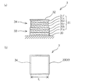
- the luminous body 1 is obtained by firing a granular laminate 3 as shown in FIG.
- the laminate 3 includes a luminous layer 31 having a six-layer structure of the mixture 2 and coat layers 30 and 32.
- the laminated body 3 exhibits substantially square shape by planar view.
- the luminous layer 31 is composed of a lower layer portion 33 composed of the first layer 31a to the third layer 31c and an upper layer portion 34 composed of the fourth layer 31d to the sixth layer 31f.
- the area of the plane orthogonal to the stacking direction is larger in each layer 31a-31c of the lower layer portion 33 than in each layer 31d-31f of the upper layer portion 34.
- the finish of the surface of the luminous body 1 becomes smooth.
- the side length L of the upper layer portion 34 is set to be about 10% smaller than one side of the lower layer portion 33.
- the base coat layer 30 is provided under the lower layer of the first layer 31 a as the lowermost layer, and the overcoat layer 32 is provided on the sixth layer 31 f as the uppermost layer of the phosphorescent layer 31.
- These coat layers 30, 32 are made of glass frit not containing a phosphorescent pigment.
- the base coat layer 30 is useful for sharpening the corners as described later.
- the luminous pigment contained in the luminous layer 31 has a large particle diameter, unevenness may be formed on the surface of the luminous body 1 by the luminous pigment.
- the overcoat layer 32 containing no phosphorescent pigment
- the overcoat layer 32 is melted by firing of the laminate 3 to prevent unevenness on the surface and make it smooth, and at the same time make corners (ends) of the laminate 3 smooth. It can be finished.
- the coat layers 30 and 32 symmetrically in the vertical direction, the balance of the surface tension at the time of melting of the laminate 3 is maintained, so that the generation of the nonuniform surface tension is prevented and the variation of the shape is prevented. Can.
- Each layer constituting the luminous layer 31 is thicker than the coat layers 30 and 32.
- the content of the luminous pigment per unit area can be efficiently increased.
- the coat layers 30 and 32 do not contain the phosphorescent pigment, the surface tension acts more largely than the phosphorescent layer 31. This makes it possible to finish the molded luminous body smoothly and to improve the light emission performance efficiently.
- the luminous pigment for example, a pigment obtained by adding and firing an activator of a rare earth element and a coactivator based on an aluminate compound of an alkaline earth metal as a main component is used.
- the alkaline earth metal include at least one or more metal elements such as calcium, strontium and barium, and alloys of these metal elements and magnesium.
- activators of rare earth elements include europium, dysprosium and the like.
- the coactivator include elements such as lanthanum, cerium, praseodymium, neodymium, samarium, cadmium, terbium, dyspronium and the like.
- the phosphorescent pigments include CaS: Bi (purple-blue emitting), CaSrS: Bi (blue emitting), ZnS: Cu (green-emitting), ZnCdS: Cu (yellow to orange emitting) And the like) can also be used.
- the above-mentioned compounds may be appropriately mixed and used, and it is possible to use other inorganic fluorescent pigments and organic fluorescent pigments having luminous property.
- the material of the glass frit may be, for example, at least one alkaline earth metal mainly composed of silicon oxide, aluminum oxide, boron oxide and alkali oxide and selected from the group consisting of calcium oxide, strontium oxide and magnesium oxide. An oxide is used.
- the material of the glass frit is not limited to the above-mentioned material, but it is preferable to use one which melts (liquefys) at a temperature at which the above-mentioned phosphorescent pigment can exist in solid form. Further, it is desirable to use a glass frit material having high transparency after firing. The light emission of the phosphorescent pigment is not inhibited, and the deterioration of the light emission performance is prevented.
- This manufacturing process generally includes a mixture forming process of forming a paste-like mixture 2, a laminate forming process of laminating the prepared paste-like mixture 2 in a plurality of layers to form a laminate 3, and a laminate 3 And baking it into a desired shape by surface tension at the time of melting.
- each powder of the luminous pigment and the glass frit and the liquid medium are mixed to form a paste-like mixture 2.
- the luminous pigment is blended so as to be in the range of 1% by weight to 40% by weight. If it is within this numerical range, it can be molded into a desired shape by the surface tension at the time of melting of the laminate 3 in the firing step without the light emission performance of the phosphorescent pigment being lowered.
- an appropriate amount of liquid medium is mixed with the total amount of the prepared solid components (powdery luminous pigment and glass frit) to prepare paste-like mixture 2.
- the medium 4 for example, one liquid or two liquid type such as acrylic type, alkyd type, epoxy type, urethane type, acrylic silicon type, fluorine type and melamine type can be used.
- the medium is not limited to the above-described materials as long as it serves as a link between the powdery luminous pigment and the glass frit in order to be formed into the granular luminous body 1.
- additives such as a dye other than the phosphorescent pigment, the glass frit, and the medium may be added within a range that does not affect the light emission performance.
- the mixture 2 described above is screen-printed on the transfer paper 20 as a support member by the printing machine 10 to simultaneously form a plurality of the laminates 3 described above.
- the transfer paper 20 is composed of a transfer layer 22 as a support layer consisting of a base 21 and a resin film, and a water-soluble adhesive layer 23 for bonding these.
- a transfer layer 22 may be made of any material that has adhesiveness to the laminate 3 and that burns off when the laminate 3 is fired.
- the adhesive layer 23 is made of, for example, a paste for transfer paper such as starch, dextrin, polyvinyl alcohol, polyvinyl pyrrolidone, gum arabic, water-soluble acrylic resin and the like.
- the screen plate 12 'in which the opening 13 is formed is attached to the printing machine 10.
- the transfer paper 20 is placed on the table 11, and the transfer paper 20 is aligned with the attached screen plate 12 '.
- the transfer sheet 20 is fixed to the base 11 by a fixing member such as a tape so as not to cause positional displacement during screen printing.
- the base coat layer 30 is formed using the screen plate 12 'of 150 mesh.
- a paste-like glass material 2 'in which a medium and a glass frit are mixed is disposed on the screen plate 12', and the squeegee is moved on the upper surface of the screen plate 12 '.
- the glass material 2 ′ is applied so as to be pushed out to the lower surface side through the opening 13, and is applied (printed) on the transfer layer 22 of the transfer paper 20 to form the coat layer 30.
- the screen version 12 ' is then replaced with a different screen version 12 of the mesh. Since the particles of the phosphorescent pigment are large, the screen plate 12 which allows the phosphorescent pigment contained in the mixture 2 to pass through the opening 13 is selected. Moreover, the luminous layer 31 can be made thick by using the screen plate having a larger opening than the above-mentioned screen plate. Thereby, content of the luminous pigment per unit area can be increased, and the light emission performance of the luminous body 1 can be improved. In the present embodiment, the 60 mesh screen 12 is replaced.
- the paste-like mixture 2 is disposed on the screen plate 12 and the squeegee 14 is moved on the upper surface of the screen plate 12.
- the mixture 2 is applied (printed) through the opening 13 to form the first layer 31 a of the luminous layer 31 on the upper surface of the base coat layer 30.
- the layers are laminated for the number of times of printing, and the laminate 3 is sequentially laminated on the surface 22 a of the transfer layer 22.
- the luminous layer 31 having a six-layer structure of the first layer 31a to the sixth layer 31f is formed by performing screen printing six times. Then, the screen plate 12 is replaced with the 150-mesh screen plate 12 ′ again, and the overcoat layer 32 is formed on the sixth layer 31 f of the luminous layer 31.
- the shape of the opening 13 can be appropriately set to a polygonal shape such as a triangle or a quadrangle, a circle, an ellipse, or the like. Further, the opening 13 may have a plurality of openings of the same shape as in this embodiment, or may have a plurality of openings of different shapes and sizes. In the present embodiment, the openings 13 have a substantially rectangular shape, and a plurality of the openings 13 are formed at appropriate intervals.
- the medium used for the mixture 2 and glass material 2 ' may contain the organic solvent containing carbon.
- carbon of the organic solvent becomes soot and darkens, and the luminance of the phosphor 1 decreases. Therefore, a drying process is provided to dry the medium each time a layer is formed.
- the organic solvent present in the layer is completely vaporized and eliminated, thereby preventing the decrease in the luminance of the luminous body 1.
- the layer is dried every time the screen printing described above is performed to evaporate and evaporate the organic solvent. The drying step is performed, for example, by exposing to warm air for a predetermined time.
- the transfer paper 20 is dipped in water.
- the water-soluble adhesive layer 23 is dissolved, and the transfer layer 22 is peeled and separated from the backing 21 while the laminate 3 is held by the transfer layer 22.
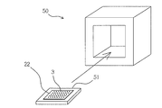
- the plurality of stacks 3 are placed on the baking base 51 by the transfer layer 22 and moved to the furnace 50.
- the surface tension of the laminate 3 is set by placing the laminate 3 in the furnace 50 in a state where the laminate 3 is positioned (oriented) on the transfer layer 22 on the underlayment 51 and firing at a predetermined temperature (for example, 800.degree. C.). Mold using.
- the transfer layer 22 is burned off by firing.
- an alumina sheet is used as the base for firing 51, but it is not particularly limited as long as the laminate 3 does not sinter, so long as it has a material and a structure.
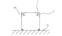
- the surface tension is a tension that acts along the surface so that the surface of the liquid shrinks as much as possible.
- the glass frit contained in the laminate 3 is melted to become a liquid glass component, and surface tension is generated in the laminate 3.
- the phosphorescent pigment has a melting point higher than that of the glass frit, and exists as a solid at the melting temperature of the glass frit. Therefore, surface tension ST which arises in layered product 3 changes with contents (blending quantity) of a luminous pigment.
- 30% by weight of the luminous pigment is contained with respect to the total amount of the prepared solid components (powdery luminous pigment and glass frit).
- a predetermined temperature for example, 800 ° C.
- the substantially square laminate 3 is rounded at each side and at the corners due to the surface tension ST.
- a light storage body 1 having a substantially cubic shape is obtained by the surface tension ST.
- the luminous pigment is prepared to be 30% by weight with respect to the total amount of the luminous pigment and the glass frit, and the laminate 3 having a substantially rectangular shape is fired to obtain the luminous body 1.
- the phosphorescent pigment is blended so as to be 5% by weight or more and 20% by weight or less based on the total amount of the phosphorescent pigment and the glass frit.
- the content of the phosphorescent pigment of the laminate 3 at the time of firing is smaller than that in the first embodiment. Therefore, the surface tension ST generated at the time of firing becomes large. Therefore, it becomes possible to manufacture spherical luminous body 1A as shown to FIG. 6 (a) (d). For example, 10% by weight of the phosphorescent pigment is blended with respect to the total amount of the phosphorescent pigment and the glass frit.
- the openings 13 of the screen plate 12 may be formed in a substantially circular shape in the laminate formation step.
- the coat layers 30 and 32 which make a pair the upper and lower sides of the luminous layer 31 of the laminated body 3 were provided.
- the coat layer 32 is not formed.
- the coat layer 30 may be appropriately provided in accordance with the shape. Further, the coat layers 30 and 32 can be provided only on one of the upper and lower layers.
- the shape of the luminous body 1 is not limited to the substantially cubic shape of the first embodiment or the spherical shape of the second embodiment.
- the phosphorescent layers 31 and 31A of the laminates 3 and 3A are formed by laminating the same mixture 2.
- each layer of the upper layer portion 34B and the middle layer portion 35B is formed of a mixture of 10% of luminous pigment content
- each layer of the lower layer portion 33B is formed of a mixture of 30% of luminous pigment.
- the surface tension in the molten state acts more greatly as the content of the phosphorescent pigment is smaller (the blending amount is smaller). Therefore, in the present embodiment, the surface tension acts largely on the upper layer portion 34B and the intermediate layer portion 35B to form a spherical surface. As a result, it is shaped as a hemispherical luminous body 1B.
- the laminate 3C has different areas of the lower layer portion 33C, the upper layer portion 34C and the middle layer portion 35C. Form a layer of seeds in steps. Then, each of the portions 33C to 35C is formed of a mixture of three kinds of luminous pigment contents different from each other.
- the lower layer portion 33C is a mixture of a 30% content of luminous pigment
- the middle layer portion 35C is a mixture of 20% content of luminous pigment
- the upper portion 34C is a mixture of 10% content of phosphorescent pigment. 3C is generated.
- the surface tension acts more greatly toward the upper layer portion 34B. As a result, it is molded as a substantially conical luminous body 1C.
- the area of the layer of the laminated body 3 was varied, and it formed in step shape.
- the arrangement of the plurality of types of layers having different layer areas can be set as appropriate without being limited to the stepped shape.
- the thickness of the several layer of the laminated body 3 was made the same.
- the laminate 3 can also be composed of multiple types of layers having different layer thicknesses.
- the surface tension of the molten state of the laminate 3 is adjusted by appropriately selecting and combining the blending amount of the phosphorescent pigment and the shape of the laminate 3 to manufacture the phosphor 1 having a desired shape. it can.
- screen printing is performed six times using the 60-mesh screen plate 12 to form a six-layered luminous layer 31, and a 150-mesh screen plate 12 'is used.
- the cover coat layer 32 was formed.
- the mesh of the screen plate and the number of times of printing are not limited to these, and can be selected appropriately.
- each layer of the luminous layer 31 of the laminate 3 is formed using the screen plate 12 of the same mesh.
- the production of the spherical luminous body 1A is not limited to screen printing, but, for example, the droplets of the mixture 2 are dropped onto the above-described transfer paper 20, and the droplets are formed on the underlayment 51 and fired. It does not matter.
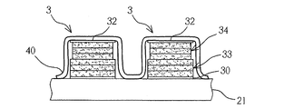
- the support layer 40 may be formed from above after printing of the laminate 3.
- the support layer 40 is made of, for example, a material such as the adhesive layer 23, in addition to resin materials such as acrylic ester copolymer, vinyl resin, cellulose resin, and other hydrocarbons.
- the support layer 40 is not particularly limited as long as it has adhesiveness with the laminate 3 and is a material that is burned off when the laminate 3 is fired. Then, the plurality of stacks 3 may be moved and placed on the base 51 and baked together with the support layer 40. Thereby, the support layer 40 is burnt out and the luminous body 1 is generated.
- the present invention can be used as a method of manufacturing a luminous body and a luminous body manufactured by the method and a luminous body.
- the luminous body manufactured by the manufacturing method according to the present invention can be used, for example, as a stone for nails, and can also be used as an accessory for artificial gems and the like.
Landscapes
- Chemical & Material Sciences (AREA)
- Engineering & Computer Science (AREA)
- Manufacturing & Machinery (AREA)
- Materials Engineering (AREA)
- Organic Chemistry (AREA)
- Dispersion Chemistry (AREA)
- Laminated Bodies (AREA)
- Adornments (AREA)
- Illuminated Signs And Luminous Advertising (AREA)
Priority Applications (2)
| Application Number | Priority Date | Filing Date | Title |
|---|---|---|---|
| US13/880,899 US9005760B2 (en) | 2010-10-22 | 2011-10-21 | Process for producing phosphorescent body and phosphorescent body produced by the process, and nail stone including phosphorescent body |
| KR1020137009636A KR101405069B1 (ko) | 2010-10-22 | 2011-10-21 | 축광체의 제조방법 및 이에 의해 제조된 축광체와 축광체를 이용한 네일용 스톤 |
Applications Claiming Priority (2)
| Application Number | Priority Date | Filing Date | Title |
|---|---|---|---|
| JP2010237753 | 2010-10-22 | ||
| JP2010-237753 | 2010-10-22 |
Publications (1)
| Publication Number | Publication Date |
|---|---|
| WO2012053641A1 true WO2012053641A1 (ja) | 2012-04-26 |
Family
ID=45975349
Family Applications (1)
| Application Number | Title | Priority Date | Filing Date |
|---|---|---|---|
| PCT/JP2011/074319 Ceased WO2012053641A1 (ja) | 2010-10-22 | 2011-10-21 | 蓄光体の製造方法及びこれにより製造された蓄光体並びに蓄光体を用いたネイル用ストーン |
Country Status (4)
| Country | Link |
|---|---|
| US (1) | US9005760B2 (enExample) |
| JP (1) | JP5392865B2 (enExample) |
| KR (1) | KR101405069B1 (enExample) |
| WO (1) | WO2012053641A1 (enExample) |
Cited By (1)
| Publication number | Priority date | Publication date | Assignee | Title |
|---|---|---|---|---|
| WO2015198939A1 (ja) * | 2014-06-23 | 2015-12-30 | コドモエナジー株式会社 | 粒状蓄光体の製造方法及び粒状蓄光体並びにガラス衝突防止安全マーク及び避難誘導用マーク |
Families Citing this family (3)
| Publication number | Priority date | Publication date | Assignee | Title |
|---|---|---|---|---|
| JP6435861B2 (ja) * | 2013-11-06 | 2018-12-12 | 東レ株式会社 | 立体構造物の製造方法、シンチレータパネルの製造方法及びシンチレータパネル |
| JP6324632B2 (ja) | 2015-01-06 | 2018-05-16 | フィリップス ライティング ホールディング ビー ヴィ | 3d印刷用のプリンタヘッド |
| KR102462131B1 (ko) | 2021-03-25 | 2022-11-03 | 현대제철 주식회사 | 용해로 버너 장치 |
Citations (4)
| Publication number | Priority date | Publication date | Assignee | Title |
|---|---|---|---|---|
| JP2005213457A (ja) * | 2004-01-30 | 2005-08-11 | Jsr Corp | プラズマディスプレイパネル用無機粉体含有樹脂組成物、転写フィルムおよびプラズマディスプレイパネルの製造方法 |
| JP2007112685A (ja) * | 2005-10-24 | 2007-05-10 | Mkk:Kk | 蓄光性発光体の製造方法 |
| JP2009203356A (ja) * | 2008-02-28 | 2009-09-10 | Toray Ind Inc | 転写成形用ガラスペースト、構造体の製造方法およびディスプレイ用部材の製造方法 |
| JP2010180380A (ja) * | 2009-02-09 | 2010-08-19 | Arise Corporate Corp | ガラス被覆蓄光性発光体粒子及びその製造方法 |
Family Cites Families (9)
| Publication number | Priority date | Publication date | Assignee | Title |
|---|---|---|---|---|
| JPS60176933A (ja) | 1984-02-20 | 1985-09-11 | Shigaken | 蓄光螢光性のガラス繊維及びガラス小球の製造方法 |
| JPH09278496A (ja) | 1996-04-12 | 1997-10-28 | Takagi Kogyo Kk | 発光性ガラスタイルとその製造法 |
| JPH1143349A (ja) | 1997-04-28 | 1999-02-16 | Kurasutaa Technol Kk | 蓄光素材並びにその製造方法 |
| JP3789038B2 (ja) * | 1998-04-02 | 2006-06-21 | 日本カーバイド工業株式会社 | 情報表示装置 |
| JP2004359480A (ja) | 2003-06-03 | 2004-12-24 | Kajiwara Tensha:Kk | 転写紙 |
| WO2004113449A1 (ja) * | 2003-06-17 | 2004-12-29 | Jsr Corporation | プラズマディスプレイパネル用転写フィルム並びにプラズマディスプレイパネルおよびその製造方法 |
| JP2007182529A (ja) * | 2005-05-11 | 2007-07-19 | Nippon Electric Glass Co Ltd | 蛍光体複合ガラス、蛍光体複合ガラスグリーンシート及び蛍光体複合ガラスの製造方法 |
| JP5044181B2 (ja) | 2006-09-27 | 2012-10-10 | アライズ・コーポレート株式会社 | 蓄光性発光体の製造方法 |
| JP4338749B2 (ja) | 2006-10-25 | 2009-10-07 | 株式会社サカイ・シルクスクリーン | 蓄光板の製造方法及び蓄光板 |
-
2011
- 2011-10-21 WO PCT/JP2011/074319 patent/WO2012053641A1/ja not_active Ceased
- 2011-10-21 JP JP2011231846A patent/JP5392865B2/ja active Active
- 2011-10-21 US US13/880,899 patent/US9005760B2/en active Active
- 2011-10-21 KR KR1020137009636A patent/KR101405069B1/ko active Active
Patent Citations (4)
| Publication number | Priority date | Publication date | Assignee | Title |
|---|---|---|---|---|
| JP2005213457A (ja) * | 2004-01-30 | 2005-08-11 | Jsr Corp | プラズマディスプレイパネル用無機粉体含有樹脂組成物、転写フィルムおよびプラズマディスプレイパネルの製造方法 |
| JP2007112685A (ja) * | 2005-10-24 | 2007-05-10 | Mkk:Kk | 蓄光性発光体の製造方法 |
| JP2009203356A (ja) * | 2008-02-28 | 2009-09-10 | Toray Ind Inc | 転写成形用ガラスペースト、構造体の製造方法およびディスプレイ用部材の製造方法 |
| JP2010180380A (ja) * | 2009-02-09 | 2010-08-19 | Arise Corporate Corp | ガラス被覆蓄光性発光体粒子及びその製造方法 |
Cited By (3)
| Publication number | Priority date | Publication date | Assignee | Title |
|---|---|---|---|---|
| WO2015198939A1 (ja) * | 2014-06-23 | 2015-12-30 | コドモエナジー株式会社 | 粒状蓄光体の製造方法及び粒状蓄光体並びにガラス衝突防止安全マーク及び避難誘導用マーク |
| JP2017057138A (ja) * | 2014-06-23 | 2017-03-23 | コドモエナジー株式会社 | 粒状蓄光体並びにこれを用いたガラス衝突防止安全マーク及び避難誘導用マーク |
| JPWO2015198939A1 (ja) * | 2014-06-23 | 2017-04-20 | コドモエナジー株式会社 | 粒状蓄光体の製造方法 |
Also Published As
| Publication number | Publication date |
|---|---|
| KR20130056341A (ko) | 2013-05-29 |
| JP2012106918A (ja) | 2012-06-07 |
| US20130263872A1 (en) | 2013-10-10 |
| KR101405069B1 (ko) | 2014-06-10 |
| JP5392865B2 (ja) | 2014-01-22 |
| US9005760B2 (en) | 2015-04-14 |
Similar Documents
| Publication | Publication Date | Title |
|---|---|---|
| TWI475730B (zh) | 藍光led上之含透明粒子的磷光體層 | |
| US8164254B2 (en) | Light-emitting device and manufacturing method thereof | |
| CN102986032B (zh) | 发光结构及其制法 | |
| JP5392865B2 (ja) | 蓄光体の製造方法及びこれにより製造された蓄光体並びに蓄光体を用いたネイル用ストーン | |
| KR100655945B1 (ko) | 전계방출디스플레이패널용형광체패턴의제조방법,전계방출디스플레이패널용감광성소자,전계방출디스플레이패널용형광체패턴및전계방출디스플레이패널 | |
| CN110136595A (zh) | 一种显示面板及其制备方法、显示装置 | |
| JP2003041245A (ja) | 液状化カラー発光発色蓄光材及びその製造方法 | |
| CN103606614A (zh) | 一种白光led用荧光板及其制备工艺 | |
| JP6028294B2 (ja) | 絵柄付き蓄光体の製造方法 | |
| KR100852295B1 (ko) | 무기 입자 함유 조성물, 전사 필름 및 플라즈마디스플레이 패널의 제조 방법 | |
| JP4623572B2 (ja) | 蓄光機能を有する焼成物の製法及び蓄光機能を有する焼成物からなる避難誘導用表示部材 | |
| WO2010090312A1 (ja) | ガラス被覆蓄光性発光体粒子の製造方法 | |
| JP3996129B2 (ja) | チキソトロピー性を有する多孔性の化学発光反応体組成物 | |
| JP2004359480A (ja) | 転写紙 | |
| KR200426648Y1 (ko) | 축광성 타일 | |
| JP3436338B2 (ja) | ブラウン管用金属化発光スクリーンの製造方法 | |
| CN2497994Y (zh) | 发光艺术陶瓷画 | |
| KR102447368B1 (ko) | 하이브리드형 백색 발광장치 및 그의 제조방법 | |
| KR100589372B1 (ko) | 플라즈마 디스플레이 패널 | |
| JP4759615B2 (ja) | プラズマディスプレイパネル及びその製造方法 | |
| KR19990004794A (ko) | 플라즈마 표시소자의 형광층 형성방법 | |
| WO2006003888A1 (ja) | 粒状体、およびこれを用いたプラズマディスプレイパネルの蛍光面の形成方法 | |
| KR20040077526A (ko) | 무기 입자 함유 조성물, 전사 필름 및 플라즈마디스플레이 패널의 제조 방법 | |
| JP2000011887A5 (enExample) | ||
| JPH0494054A (ja) | 蛍光ランプ及びその製造方法 |
Legal Events
| Date | Code | Title | Description |
|---|---|---|---|
| 121 | Ep: the epo has been informed by wipo that ep was designated in this application |
Ref document number: 11834480 Country of ref document: EP Kind code of ref document: A1 |
|
| ENP | Entry into the national phase |
Ref document number: 20137009636 Country of ref document: KR Kind code of ref document: A |
|
| NENP | Non-entry into the national phase |
Ref country code: DE |
|
| WWE | Wipo information: entry into national phase |
Ref document number: 13880899 Country of ref document: US |
|
| 122 | Ep: pct application non-entry in european phase |
Ref document number: 11834480 Country of ref document: EP Kind code of ref document: A1 |