WO2012043150A1 - Appareil de formation de couche - Google Patents
Appareil de formation de couche Download PDFInfo
- Publication number
- WO2012043150A1 WO2012043150A1 PCT/JP2011/070119 JP2011070119W WO2012043150A1 WO 2012043150 A1 WO2012043150 A1 WO 2012043150A1 JP 2011070119 W JP2011070119 W JP 2011070119W WO 2012043150 A1 WO2012043150 A1 WO 2012043150A1
- Authority
- WO
- WIPO (PCT)
- Prior art keywords
- base portion
- vacuum chamber
- mask
- substrate
- drive mechanism
- Prior art date
Links
Images


Classifications
-
- H—ELECTRICITY
- H10—SEMICONDUCTOR DEVICES; ELECTRIC SOLID-STATE DEVICES NOT OTHERWISE PROVIDED FOR
- H10K—ORGANIC ELECTRIC SOLID-STATE DEVICES
- H10K71/00—Manufacture or treatment specially adapted for the organic devices covered by this subclass
- H10K71/10—Deposition of organic active material
- H10K71/16—Deposition of organic active material using physical vapour deposition [PVD], e.g. vacuum deposition or sputtering
-
- C—CHEMISTRY; METALLURGY
- C23—COATING METALLIC MATERIAL; COATING MATERIAL WITH METALLIC MATERIAL; CHEMICAL SURFACE TREATMENT; DIFFUSION TREATMENT OF METALLIC MATERIAL; COATING BY VACUUM EVAPORATION, BY SPUTTERING, BY ION IMPLANTATION OR BY CHEMICAL VAPOUR DEPOSITION, IN GENERAL; INHIBITING CORROSION OF METALLIC MATERIAL OR INCRUSTATION IN GENERAL
- C23C—COATING METALLIC MATERIAL; COATING MATERIAL WITH METALLIC MATERIAL; SURFACE TREATMENT OF METALLIC MATERIAL BY DIFFUSION INTO THE SURFACE, BY CHEMICAL CONVERSION OR SUBSTITUTION; COATING BY VACUUM EVAPORATION, BY SPUTTERING, BY ION IMPLANTATION OR BY CHEMICAL VAPOUR DEPOSITION, IN GENERAL
- C23C14/00—Coating by vacuum evaporation, by sputtering or by ion implantation of the coating forming material
- C23C14/04—Coating on selected surface areas, e.g. using masks
- C23C14/042—Coating on selected surface areas, e.g. using masks using masks
-
- C—CHEMISTRY; METALLURGY
- C23—COATING METALLIC MATERIAL; COATING MATERIAL WITH METALLIC MATERIAL; CHEMICAL SURFACE TREATMENT; DIFFUSION TREATMENT OF METALLIC MATERIAL; COATING BY VACUUM EVAPORATION, BY SPUTTERING, BY ION IMPLANTATION OR BY CHEMICAL VAPOUR DEPOSITION, IN GENERAL; INHIBITING CORROSION OF METALLIC MATERIAL OR INCRUSTATION IN GENERAL
- C23C—COATING METALLIC MATERIAL; COATING MATERIAL WITH METALLIC MATERIAL; SURFACE TREATMENT OF METALLIC MATERIAL BY DIFFUSION INTO THE SURFACE, BY CHEMICAL CONVERSION OR SUBSTITUTION; COATING BY VACUUM EVAPORATION, BY SPUTTERING, BY ION IMPLANTATION OR BY CHEMICAL VAPOUR DEPOSITION, IN GENERAL
- C23C14/00—Coating by vacuum evaporation, by sputtering or by ion implantation of the coating forming material
- C23C14/22—Coating by vacuum evaporation, by sputtering or by ion implantation of the coating forming material characterised by the process of coating
- C23C14/24—Vacuum evaporation
-
- H—ELECTRICITY
- H05—ELECTRIC TECHNIQUES NOT OTHERWISE PROVIDED FOR
- H05B—ELECTRIC HEATING; ELECTRIC LIGHT SOURCES NOT OTHERWISE PROVIDED FOR; CIRCUIT ARRANGEMENTS FOR ELECTRIC LIGHT SOURCES, IN GENERAL
- H05B33/00—Electroluminescent light sources
- H05B33/10—Apparatus or processes specially adapted to the manufacture of electroluminescent light sources
-
- H—ELECTRICITY
- H10—SEMICONDUCTOR DEVICES; ELECTRIC SOLID-STATE DEVICES NOT OTHERWISE PROVIDED FOR
- H10K—ORGANIC ELECTRIC SOLID-STATE DEVICES
- H10K59/00—Integrated devices, or assemblies of multiple devices, comprising at least one organic light-emitting element covered by group H10K50/00
-
- H—ELECTRICITY
- H10—SEMICONDUCTOR DEVICES; ELECTRIC SOLID-STATE DEVICES NOT OTHERWISE PROVIDED FOR
- H10K—ORGANIC ELECTRIC SOLID-STATE DEVICES
- H10K59/00—Integrated devices, or assemblies of multiple devices, comprising at least one organic light-emitting element covered by group H10K50/00
- H10K59/80—Constructional details
- H10K59/88—Dummy elements, i.e. elements having non-functional features
-
- H—ELECTRICITY
- H10—SEMICONDUCTOR DEVICES; ELECTRIC SOLID-STATE DEVICES NOT OTHERWISE PROVIDED FOR
- H10K—ORGANIC ELECTRIC SOLID-STATE DEVICES
- H10K71/00—Manufacture or treatment specially adapted for the organic devices covered by this subclass
-
- H—ELECTRICITY
- H10—SEMICONDUCTOR DEVICES; ELECTRIC SOLID-STATE DEVICES NOT OTHERWISE PROVIDED FOR
- H10K—ORGANIC ELECTRIC SOLID-STATE DEVICES
- H10K71/00—Manufacture or treatment specially adapted for the organic devices covered by this subclass
- H10K71/10—Deposition of organic active material
- H10K71/16—Deposition of organic active material using physical vapour deposition [PVD], e.g. vacuum deposition or sputtering
- H10K71/166—Deposition of organic active material using physical vapour deposition [PVD], e.g. vacuum deposition or sputtering using selective deposition, e.g. using a mask
Definitions
- the present invention relates to a film forming apparatus.
- the transport method in an organic EL display panel manufacturing apparatus has a substrate size of, for example, a fourth-generation half-cut size or less, and the glass substrate is not bent due to gravity. ing.
- an alignment driving mechanism that aligns a substrate (substrate tray) and a mask (mask tray) in a vertical state is disclosed in, for example, Patent Document 1.
- An alignment drive mechanism is used, which is similar to that used in horizontal conveyance, in which the alignment drive unit is arranged in a direction perpendicular to the substrate / mask surface. Since it protrudes greatly in the conveyance direction and the direction perpendicular to the horizontal direction), a large installation space is required, which is not preferable.
- the present invention has been made in view of the current situation as described above, and the alignment drive mechanism is divided into two upper and lower parts and installed in a chamber as a rigid body, thereby realizing space saving while ensuring alignment accuracy. It is an object of the present invention to provide an extremely practical film forming apparatus that can handle a large substrate of a generation or more.
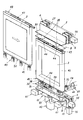
- a film forming apparatus for forming a film by attaching a film forming material to a substrate 2 held in an upright state in a vacuum chamber 1 through a mask 3, and an alignment frame 4 having the mask 3 attached in an upright state.
- An alignment drive mechanism that adjusts and moves relative to the substrate 2 and aligns the mask 3 and the substrate 2 so that the mask 3 is in an appropriate position with respect to the substrate 2 is provided.
- an upper side fixed base portion 5 provided outside the vacuum chamber 1 and fixed to the upper side of the vacuum chamber 1, and an X direction and a Y direction parallel to the mask surface with respect to the upper side fixed base portion 5
- an upper side moving base part 6 which is movable to the upper side of the vacuum chamber 1 and one end of which is supported by the upper side moving base part 6 so as to be rotatable in the ⁇ direction which is the rotational direction on the mask surface.
- Upper through-hole 7 provided An upper drive mechanism comprising an upper connecting body 8 connected to the upper part of the alignment frame 4 in the vacuum chamber 1 or fixed to the lower side of the vacuum chamber 1 provided outside the vacuum chamber 1
- a lower-side fixed base portion 9 a lower-side moving base portion 10 movable in the X and Y directions parallel to the mask surface relative to the lower-side fixed base portion 9, and one end rotating on the mask surface
- the other end is supported by the lower moving base 10 so as to be rotatable in the ⁇ direction, and the other end is formed at the lower portion of the alignment frame 4 in the vacuum chamber 1 through a lower through hole 11 provided in the lower portion of the vacuum chamber 1.
- the lower-side drive mechanism is composed of a lower-side connecting body 12 to be connected, and the upper-side connecting body 8 and the lower-side connecting body 12 are connected to the alignment frame 4 through the upper through hole 7 and the lower through-hole. Seal the holes 11 in an airtight state.
- Those of the film forming apparatus characterized by via a bellows 34, 35 provided in the vacuum chamber 1.
- the film forming apparatus performs film formation by depositing a film forming material on a substrate 2 held in an upright state in a vacuum chamber 1 through a mask 3, and the alignment frame has the mask 3 attached in an upright state.
- 4 is provided with an alignment driving mechanism for aligning the mask 3 and the substrate 2 so that the mask 3 is in an appropriate position with respect to the substrate 2 by adjusting and moving the substrate 4 with respect to the substrate 2.
- the driving mechanism is provided on the outside of the vacuum chamber 1 and fixed to the upper side of the vacuum chamber 1. The driving mechanism is fixed to the upper side of the vacuum chamber 1.
- An upper side moving base portion 6 that can move in the Y direction, one end of which is supported by the upper side moving base portion 6 so as to be rotatable in the ⁇ direction that is the rotation direction on the mask surface, and the other end of the vacuum chamber 1.
- Upper penetration An upper drive mechanism composed of an upper connecting body 8 connected to the upper part of the alignment frame 4 in the vacuum chamber 1 through a hole 7, and provided outside the vacuum chamber 1 and fixed to the lower side of the vacuum chamber 1.
- the other end is supported by the lower moving base 10 so as to be rotatable in the ⁇ direction, and the other end is formed at the lower portion of the alignment frame 4 in the vacuum chamber 1 through a lower through hole 11 provided in the lower portion of the vacuum chamber 1.
- a lower drive mechanism comprising a lower connection body 12 to be connected, and the connection portion of the upper connection body 8 and the lower connection body 12 to the alignment frame 4 is the upper through-hole 7 and the lower part. Seal each through hole 11 in an airtight state.
- the film forming apparatus performs film formation by depositing a film forming material on a substrate 2 held in an upright state in a vacuum chamber 1 through a mask 3, and the alignment frame has the mask 3 attached in an upright state.
- 4 is provided with an alignment driving mechanism for aligning the mask 3 and the substrate 2 so that the mask 3 is in an appropriate position with respect to the substrate 2 by adjusting and moving the substrate 4 with respect to the substrate 2.
- the driving mechanism is provided on the outside of the vacuum chamber 1 and fixed to the upper side of the vacuum chamber 1. The driving mechanism is fixed to the upper side of the vacuum chamber 1.
- An upper side moving base portion 6 that can move in the Y direction, one end of which is supported by the upper side moving base portion 6 so as to be rotatable in the ⁇ direction that is the rotation direction on the mask surface, and the other end of the vacuum chamber 1.
- Upper penetration An upper drive mechanism comprising an upper connecting body 8 connected to the upper portion of the alignment frame 4 in the vacuum chamber 1 through a hole 7 or provided on the lower side of the vacuum chamber 1 provided outside the vacuum chamber 1.
- the lower end of the alignment frame 4 in the vacuum chamber 1 is supported by the lower-side moving base portion 10 so as to be rotatable in the ⁇ direction which is the rotation direction, and the other end is provided through a lower through hole 11 provided in the lower portion of the vacuum chamber 1.
- a lower drive mechanism comprising a lower connecting body 12 connected to the upper drive mechanism or the lower drive mechanism is provided with an X-direction drive device or a Y-direction drive device or both.
- the alignment frame 4 can be adjusted and moved in the X, Y, and ⁇ directions via the upper side connection body 8 or the lower side connection body 12, and the upper side connection body 8 and the lower side connection body.
- the connecting portion of 12 to the alignment frame 4 is provided in the vacuum chamber 1 through bellows 34 and 35 for sealing the upper through hole 7 and the lower through hole 11 in an airtight state, respectively.
- the present invention relates to a film forming apparatus.
- the film forming apparatus performs film formation by depositing a film forming material on a substrate 2 held in an upright state in a vacuum chamber 1 through a mask 3, and the alignment frame has the mask 3 attached in an upright state.
- 4 is provided with an alignment driving mechanism for aligning the mask 3 and the substrate 2 so that the mask 3 is in an appropriate position with respect to the substrate 2 by adjusting and moving the substrate 4 with respect to the substrate 2.
- the driving mechanism is provided on the outside of the vacuum chamber 1 and fixed to the upper side of the vacuum chamber 1. The driving mechanism is fixed to the upper side of the vacuum chamber 1.
- An upper side moving base portion 6 that can move in the Y direction, one end of which is supported by the upper side moving base portion 6 so as to be rotatable in the ⁇ direction that is the rotation direction on the mask surface, and the other end of the vacuum chamber 1.
- Upper penetration An upper drive mechanism composed of an upper connecting body 8 connected to the upper part of the alignment frame 4 in the vacuum chamber 1 through a hole 7, and provided outside the vacuum chamber 1 and fixed to the lower side of the vacuum chamber 1.
- the other end is supported by the lower moving base 10 so as to be rotatable in the ⁇ direction, and the other end is formed at the lower portion of the alignment frame 4 in the vacuum chamber 1 through a lower through hole 11 provided in the lower portion of the vacuum chamber 1.
- a lower-side drive mechanism comprising a lower-side connecting body 12 to be connected, and the upper-side drive mechanism and the lower-side drive mechanism are each provided with an X-direction drive device and / or a Y-direction drive device,
- This X direction drive By moving the upper side moving base part 6 and the lower side moving base part 10 with respect to the upper side fixed base part 5 and the lower side fixed base part 9 in the X direction and the Y direction by the Y-direction drive device,
- the alignment frame 4 can be adjusted and moved in the X, Y, and ⁇ directions via the upper side connection body 8 and the lower side connection body 12, and the upper side connection body 8 and the lower side connection body 12.
- the connecting portion to the alignment frame 4 is provided in the vacuum chamber 1 via bellows 34 and 35 for sealing the upper through hole 7 and the lower through hole 11 in an airtight state, respectively.
- the present invention relates to a membrane device.
- the Y-direction drive device provided in the lower-side drive mechanism that moves the lower-side movement base portion 10 in the Y-direction that is the vertical direction parallel to the mask surface includes the lower-side movement base portions 10. 5.
- each of the film forming apparatuses is configured to be independently movable, and the upper-side drive mechanism is not provided with the Y-direction drive device.
- the upper-side moving base portion 6 is connected to the upper-side fixed base portion 5 via a linear motion guide portion that guides the upper-side moving base portion 6 in the X direction and the Y direction with respect to the upper-side fixed base portion 5.
- the upper side connecting body 8 is connected to each upper side moving base part 6 via a rotation guide part that guides the upper side connecting body in the ⁇ direction with respect to each upper side moving base part 6.
- the lower-side moving base portion 10 is connected to the lower-side fixed base portion 9 via a linear motion guide portion that guides the lower-side moving base portion 10 in the X and Y directions with respect to the lower-side fixed base portion 9.
- the lower-side connecting body 12 is connected to each lower-side moving base portion 10 via a rotation guide portion that guides the lower-side connecting body 12 in the ⁇ direction with respect to each lower-side moving base portion 10.
- the present invention is configured as described above, it achieves a space saving while ensuring alignment accuracy, and is a very practical film forming apparatus that can be applied to a large substrate of the fourth generation or higher.
- the upper side moving base portion 6 and the lower side moving base portion 10 are respectively fixed to the upper and lower fixed bases. It moves with respect to the parts 5 and 9 so that it moves integrally with the alignment frame 4 and the alignment frame 4 via the upper side connecting body 8 or the lower side connecting body 12 provided in each of the moving base parts 6 and 10.
- the mask 3 to be attached is adjusted and moved in the X, Y, and ⁇ directions with respect to the substrate 2.
- the present invention relates to the upper side fixed base portion 5 or the lower side fixed base portion 6 of the upper side driving mechanism or the lower side driving mechanism arranged outside or in the lower side of the vacuum chamber 1 (chamber).
- an alignment driving mechanism is used as in the prior art. It is possible to arrange compactly above or below the vacuum chamber 1 or both without projecting in the direction perpendicular to the conveyance direction and the horizontal direction, and to reduce the installation space on the plane layout as much as possible. Can do.
- each fixed base part 5 and 9 is provided in the chamber as a rigid body, sufficient alignment accuracy can be ensured. Further, the central space can be enlarged, and installation of a substrate cooling mechanism, a mask cooling mechanism, a mask suction mechanism, or the like is facilitated accordingly. Further, the holding moment of the mask 3 is reduced, the influence on the alignment accuracy can be reduced, and the increase in the substrate size can be dealt with. Accordingly, the drive mechanism can be made as compact as possible, and the distance between the drive mechanism and the connecting portion between each of the connecting bodies 8 and 12 can be shortened, so that precise alignment adjustment movement is possible.
- a driving device for moving the upper and lower moving base parts 6 and 10 can be provided separately on the upper and lower parts of the vacuum chamber 1, for example, a pair (two pieces) provided at predetermined intervals.
- a ball screw device to move in the Y direction (two axes for each moving base portion).
- a ball screw mechanism (one axis) for moving the upper side moving base portion 6 in the X direction relative to the upper side fixed base portion 5 can be provided on the upper side (each upper side moving base). Since the part 6 and the lower side moving base part 10 are connected by the upper side connecting body 8 and the lower side connecting body 12, they move in conjunction with each other).
- the alignment frame 4 can be adjusted and moved freely in the X, Y, and ⁇ directions, and the upper driving device can be reduced.
- connection parts of the respective connecting bodies 8 and 12 to the alignment frame 4 are arranged in the vacuum chamber 1 (vacuum side), and all the frictional contact portions of the alignment drive mechanism are outside the vacuum chamber 1 (atmosphere). Therefore, the interior of the vacuum chamber 1 can be maintained in a clean atmosphere, and the thin film to be formed can be of higher quality.
- the present invention realizes space saving while ensuring alignment accuracy, and is extremely practical for handling a large substrate of the fourth generation or higher.
- the present invention is applied to a film forming chamber of a film forming apparatus (vacuum evaporation apparatus) provided with a transport mechanism for transporting a substrate and a mask (vertical transport) in a vertically upright state standing vertically to a horizontal direction. It is applied.
- a film forming apparatus vacuum evaporation apparatus
- a transport mechanism for transporting a substrate and a mask vertical transport in a vertically upright state standing vertically to a horizontal direction. It is applied.
- this embodiment is a film forming apparatus for forming a film by depositing a film forming material on a substrate 2 held in an upright state in a vacuum chamber 1 through a mask 3, and the mask 3 is in an upright state.
- An alignment driving mechanism that adjusts and moves the alignment frame 4 attached to the substrate 2 to align the mask 3 with the substrate 2 so that the mask 3 is in an appropriate position with respect to the substrate 2.
- the alignment drive mechanism is provided outside the vacuum chamber 1 and is fixed to the upper side of the vacuum chamber 1.
- the alignment drive mechanism is provided on the mask surface with respect to the upper side fixed base portion 5.
- An upper-side moving base portion 6 that can move in parallel X and Y directions, one end is supported by the upper-side moving base portion 6 so as to be rotatable in the ⁇ direction, which is the rotation direction on the mask surface, and the other end.
- An upper drive mechanism comprising an upper connecting body 8 connected to the upper part of the alignment frame 4 in the vacuum chamber 1 through the upper through hole 7 and a lower portion of the vacuum chamber 1 provided outside the vacuum chamber 1.
- the alignment frame 4 in the vacuum chamber 1 is supported by the lower-side moving base portion 10 so as to be rotatable in the ⁇ direction which is the upper rotation direction, and the other end through a lower through hole 11 provided in the lower portion of the vacuum chamber 1.
- the lower side driving mechanism is composed of a lower side connecting body 12 connected to the lower part of the upper side connecting body 8, and the upper side connecting body 8 and the lower side connecting body 12 are connected to the alignment frame 4 at the upper through hole 7. And the lower through-hole 11 are hermetically sealed. Through the bellows 34, 35 is sealed with a state in which provided in the vacuum chamber 1.
- the vacuum chamber 1 (deposition chamber) is connected in a straight line to each of the chambers on the carry-in side and the carry-out side via a gate valve so as to maintain an airtight state, and has an appropriate pressure reducing mechanism.
- an evaporation source for the film forming material is arranged so as to face the substrate 2, and when the film is formed, an alignment driving mechanism is used to superpose the substrate 2 and the mask 3 in a state where they are aligned at appropriate positions.
- the glass substrate 2 is attached to the substrate tray 41
- the mask 3 is attached to a frame-shaped mask frame (not shown), and this mask frame is a frame-shaped mask. It is attached to the tray 42 (when the substrate size is 5th generation or 5.5th generation).
- a mask with the mask 3 attached to the mask frame may be employed depending on the substrate size (for example, in the case of the sixth generation).
- an upper guide body 43 having a substantially U shape in cross section is provided on the upper portion of the mask tray 42.
- a round bar-shaped lower guide body 45 is provided below the mask tray 42.
- the mask 3 is conveyed by the lower guide body 45 while being guided by a conveying roller 46 (V roller) provided on the inner lower surface side of the vacuum chamber 1. Specifically, the transport roller 46 is erected on the bottom surface of the vacuum chamber 1. An insertion hole 39 is provided in the bottom surface of the lower guide body 45, and the mask 3 can be fixed at the time of alignment by inserting a positioning pin 38 to be described later.
- V roller conveying roller
- the substrate tray 41 is provided with an upper guide body 48 that is substantially U-shaped in cross-section, with which the guide roller 47 abuts, and a lower guide body 50 that is transported while being guided by the transport roller 49 (V roller). Yes.
- the bottom surface of the upper guide body 48 and the bottom surface of the lower guide body 50 are provided with insertion holes into which the substrate tray lock pins are inserted.
- a cooling plate for cooling the substrate tray 41 and a mask 3 (made of a magnetic material such as Invar) and the substrate 2 are provided.
- a recess is provided for providing a plate 51 having a magnet plate to be brought into close contact with.
- alignment marks are respectively provided on the front side corners of the substrate 2 and the back side corners of the mask 3 (a pair of corners at diagonal positions).
- This alignment mark is configured to be visible by an alignment camera 54 comprising a CCD camera, a lens and illumination through alignment mark visualizing holes 52 and 53 provided in the substrate tray 41 and the plate 51.
- the alignment is performed by controlling the alignment drive mechanism based on the image from the alignment camera 54.
- the alignment drive mechanism will be described in detail.
- the upper-side moving base portion 6 is connected to the upper-side fixed base portion 5 via a linear motion guide portion that guides the upper-side moving base portion 6 in the X and Y directions with respect to the upper-side fixed base portion 5.
- the upper-side connecting body 8 is connected to each upper-side moving base portion 6 via a rotation guide portion that guides the upper-side connecting body in the ⁇ direction with respect to each upper-side moving base portion 6.
- the lower-side moving base portion 10 is connected to the lower-side fixed base portion 5 via a linear motion guide portion that guides the lower-side moving base portion 10 in the X and Y directions with respect to the lower-side fixed base portion 9.
- the lower-side connecting body 12 is connected to the lower-side moving base portions 10 via a rotation guide portion that guides the lower-side connecting body 12 in the ⁇ direction with respect to the lower-side moving base portions 10. ing.
- the upper fixed base portion 5 is provided in a fixed state outside the upper wall surface of the vacuum chamber 1 (chamber).
- a plate-like upper side X-direction moving base 14 is provided via two LM (Linear Motion) guides formed by fitting the upper side X-direction moving base 14 on the mounting surface parallel to the mask surface of the upper side X-direction.
- a plate-like upper side Y-direction movement base 17 is provided via two LM guides formed by fitting a guide block 19 on a rail 18 extending in the (vertical direction) to constitute the upper side movement base portion 6. ing.
- the surface facing the mounting surface of the upper side fixed base portion 5 of the upper side X-direction moving base 14 is set to a surface parallel to the mask surface, and the mounting flat surface of the guide block 16 is mounted and fixed on this surface. Further, the surface of the upper side Y-direction moving base 17 facing the mounting surface of the upper side X-direction moving base 14 is set to a surface parallel to the mask surface, and the mounting flat surface of the guide block 19 is attached and fixed to this surface.
- the lower side fixed base portion 9 is provided in a fixed state on the lower wall surface outside the vacuum chamber 1 on the lower side.
- a movable base 20 is provided, and two LM guides are formed by fitting a guide block 25 to a rail 24 extending in the X direction on a mounting surface parallel to the mask surface of the lower Y-direction movable base 20.
- a plate-like lower side X-direction moving base 23 is provided to constitute the lower side moving base portion 10.
- the surface facing the mounting surface of the lower side fixed base portion 9 of the lower side Y-direction moving base 20 is set to a surface parallel to the mask surface, and the mounting flat surface of the guide block 22 is fixedly mounted on this surface. Further, the lower surface of the lower X direction moving base 23 and the mounting surface of the lower Y direction moving base 20 facing the mounting surface are set parallel to the mask surface, and the mounting flat surface of the guide block 25 is fixedly mounted on this surface.
- the vertical arrangement relationship between the X-direction movement base and the Y-direction movement base is reversed by the upper and lower drive mechanisms in consideration of balance, but they may be matched.
- the upper side moving base part 6 and the lower side moving base part 10 are provided in pairs (two each) on the left and right sides.
- each upper side moving base portion 6 On the mounting surface parallel to the mask surface of each upper side moving base portion 6, a cross-sectional bearing L-shaped plate member of the upper side connecting body 8 is provided via a cross roller bearing 13 provided so that the outer ring can turn with respect to the inner ring.
- a vertical surface of one base portion 27 is provided, and the base portion 27 is provided on each upper moving base portion 6 in a erected state.
- a cross-sectional view of the lower coupling body 12 is provided on the mounting surface parallel to the mask surface of each lower side moving base portion 10 via a cross roller bearing 26 provided so that the outer ring can turn with respect to the inner ring.
- a vertical surface of one base portion 29 made of an L-shaped plate material is provided, and the base portion 29 is provided in a state of being erected on each lower-side moving base portion 6.
- the mask 3 is attached in an upright state to the left and right ends (positions corresponding to the cross roller bearings 13) of the horizontal plane orthogonal to the vertical surface of the base portion 27 of the upper side connecting body 8 provided on the upper side moving base portion 6, respectively.
- a connecting cylinder 28 connected to the alignment frame 4 is erected.
- each connecting cylinder 28 is introduced into the vacuum chamber 1 through the upper through-hole 7 of the vacuum chamber 1, and a guide roller 44 (in the mask positioning and fixing position) is provided at this leading end for guiding the mask.
- a horizontal plate 30 connected to the alignment frame 4 is connected in an erected state.
- the guide roller 44 includes a roller body 70 that contacts the inner bottom surface of the upper guide body 43, a roller body 71 that contacts the inner surface, and these roller bodies 70 and 71 are rotatable.
- the roller holder 72 is held, and a pair of slide bushes 73 that support the roller holder 72 so as to be movable toward and away from the surface of the horizontal plate 30.
- the roller holder 72 is biased in a direction away from the horizontal plate 30 by a biasing mechanism such as a spring.
- the horizontal plate 30 is provided with a positioning pin 36 having a fitting portion to be fitted into the fitting hole 37 of the mask 3 at the tip.
- the positioning pin 36 is provided between the slide bushes 73 of the guide roller 44, and the tip thereof is provided so as to protrude from an insertion hole provided at the center of the roller holder 72 of the guide roller 44.
- the insertion portion at the tip of the positioning pin 36 is normally configured not to protrude from the roller bodies 70 and 71.
- the roller holding body 72 is pushed up against the urging force of the urging mechanism, the roller body It is configured so as to protrude (exposure) from 70 and 71 and be fitted into the fitting hole 37 of the upper guide body 43.
- the mask 3 (mask tray 42) is pushed upward by a positioning pin 38, which will be described later, and the roller holder 72 is pushed up by the upper guide body 43 via the roller body 70, the fitting portion at the tip of the positioning pin 36 is exposed. Then, it is inserted into the insertion hole 37 of the upper guide body 43.
- a metal bellows 34 (expandable tube) is provided so as to cover the connecting cylinder 28.
- One end of the bellows 34 is disposed at the peripheral edge of the upper through hole 7, and the other end is disposed on the upper surface side of the horizontal plate 30, whereby the upper through hole 7 is sealed in an airtight state.
- the lower side is provided with masks 3 at left and right end portions (positions corresponding to the cross roller bearings 26) of the horizontal plane orthogonal to the vertical surface of the base portion 29 of the lower side connecting body 12 provided on the lower side moving base portion 10, respectively.
- a connecting cylinder 31 connected to the alignment frame 4 attached in an upright state is erected.
- each connecting cylinder 31 is introduced into the vacuum chamber 1 through the lower through hole 11 of the vacuum chamber 1, and a horizontal plate 33 connected to the alignment frame 4 is connected to the distal end portion in an erected state.
- the connecting cylinder 31 has a leading end that passes through the horizontal plate 33 (in a state where airtightness without gaps can be maintained) and protrudes upward, and is inserted into the connecting cylinder 31 from the leading end of the connecting cylinder 31.
- a cylindrical body 60 that protrudes in a state that can maintain airtightness without a gap is provided, and a positioning pin 38 can be protruded and retracted from the tip by an appropriate protruding and retracting drive mechanism 61 such as an eccentric cam mechanism inside the cylindrical body 60. Is provided.
- the protruding amount of the positioning pin 38 is pushed up so that at least the lower guide body 50 of the mask tray 42 is separated from the conveying roller 46 by being inserted into the insertion hole 39, and the roller body 70 is driven by the upper guide body 43 of the mask tray 42.
- the roller holding body 72 is pushed up through the position so that the insertion portion at the tip of the positioning pin 36 can be exposed.
- outer peripheral surface of the positioning pin 38 and the inner peripheral surface of the tip of the cylindrical body 60 are configured to be able to slide in and out while maintaining airtightness.
- the positioning pin 38 protrudes from the tip of the cylindrical body 60 and is inserted into the insertion hole 39 of the mask 3, and the mask 3 (mask tray 42) is pushed up and the roller holding body 72 is pushed up by the upper guide body 43.
- the mask 3 can be positioned and fixed with respect to the upper connection body 8 and the lower connection body 12 by inserting the exposed insertion portion of the exposed positioning pin 36 into the insertion hole 37, and the mask 3 is aligned with the alignment frame 4. Can be fixed together.
- a metal bellows 35 is provided so as to cover the connecting cylinder 31.
- One end of the bellows 35 is disposed on the peripheral edge of the lower through hole 11, and the other end is disposed on the lower surface side of the horizontal plate 33, whereby the lower through hole 11 is sealed in an airtight state.
- the alignment frame 4 is connected to the horizontal plates 30 and 33, respectively. Therefore, the alignment frame 4 and the coupling bodies 8 and 12 move together. That is, the alignment frame 4 is moved in the X, Y, and ⁇ directions together with the coupling bodies 8 and 12 that move in the X, Y, and ⁇ directions under the influence of the movement of the left and right moving base portions 6 and 10. Moving.
- the alignment frame 4 is provided with a cooling mechanism for cooling the mask.
- the upper side drive mechanism and the lower side drive mechanism are each provided with an X-direction drive device and / or a Y-direction drive device, and the X-direction drive device and the Y-direction drive device provide the upper part.
- the upper side connecting body 8 and the lower side moving base portion 10 are moved.
- the alignment frame 4 can be adjusted and moved in the X, Y, and ⁇ directions via the side coupling body 12.
- the ball screw device includes a motor 55 that can rotate forward and backward, and a ball screw 56 (fixed portion) that is rotated by the motor 55, and an axial direction of the ball screw 56 that is engaged with the ball screw 56 and rotated by the ball screw 56. And a nut 57 (moving part) that moves to
- a motor 55 and a ball screw 56 are provided on the left and right ends of the lower fixed base portion 9 (attachment surface thereof), and this ball screw 56 extends in the Y direction.
- the lower-side fixed base 20 of the lower-side Y-direction moving base 20 of the lower-side moving base 10 provided at the left and right ends of the lower-side fixed base 9 is fixed between the two rails 21 in parallel.
- a nut 57 that is screwed with the ball screw 56 is attached to the surface facing the base portion 9, and is driven in the Y direction.
- a motor 55 and a ball screw 56 are placed on the lower side Y-direction moving base 20 of the lower side moving base portion 10 provided at the right end, and the ball screw 56 extends between the rails 24 extending in the X direction.
- a nut 57 that is screwed with the ball screw 56 is attached to the surface of the lower side X-direction moving base 23 that faces the lower side Y-direction moving base 20 and is driven in the X direction. It is configured as follows.
- a motor 55 and a ball screw 56 are provided at one end (right end) of the upper side fixed base portion 5 (attachment surface thereof), and the rail is provided between the rails 15 where the ball screw 56 extends in the X direction.
- 15 is fixed to be parallel to the upper side fixed base portion 5, and the upper side moving base portion 6 provided at the right end of the upper side fixed base portion 5 is opposed to the upper side fixed base portion 5 of the upper side X-direction moving base 14.
- a nut 57 to be screwed with the ball screw 56 is attached and configured to be driven in the X direction.
- the upper side connecting body 8 and the lower side connecting body 12 and the alignment frame 4 move together, the above four ball screw devices (hereinafter, the lower side X direction driving device is referred to as A, lower left side Y direction).
- the lower side X direction driving device is referred to as A, lower left side Y direction.
- the lower side X-direction moving base 23 is sent leftward by A
- the upper side X-direction moving base 14 is sent rightward by D
- the lower side Y-direction moving base left is sent by B.
- the alignment frame 4 (mask 3) can also be rotated via the cross roller bearing by feeding 20 upward and feeding the lower Y side moving base 20 on the right side downward by C.
- the mask 3 can be precisely aligned with the substrate 2 based on the alignment mark.
- the mass is canceled by supplying air pressure corresponding to the load, and the Y-axis drive load A balancer cylinder 62 for reducing the above is provided.
- the connecting portion with the lower drive mechanism is connected via an LM guide 63 so as not to limit the alignment operation.
- the lock mechanism of the substrate 2 and the reciprocating mechanism with respect to the mask 3 are configured as follows.
- the lock mechanism of the substrate 2 includes an eccentric cam 32 that raises the substrate 2 (substrate tray 41), and a bottom surface of the lower guide body 50 of the substrate tray 41 that is raised by the eccentric cam 32.
- a substrate tray lock pin (moves back and forth with respect to the mask 3 together with the eccentric cam 32) to be inserted into the insertion hole, and a guide roller to be inserted into a V-shaped groove provided on the bottom surface of the upper guide body 48 when the substrate tray 41 is raised. It consists of 47 tapered roller bodies.
- the reciprocating mechanism with respect to the mask 3 includes a support 66 for supporting the eccentric cam 32, a support 69 for supporting the guide roller 47, and vacuuming the supports 66 and 69.
- the LM guide 67 is slidably supported with respect to the tank 1 in a direction orthogonal to the surface direction of the mask 3 and the horizontal direction, and a slide moving mechanism 75 for slidingly moving these supports 66 and 69.
- the slide moving mechanism 75 includes a servo motor and a ball screw unit driven by the servo motor, and a moving base 78 that moves in the direction perpendicular to the surface direction of the mask 3 along the LM guide 76 by the ball screw unit. And a connecting portion 74 that connects the moving base 78 and the supports 66 and 69.
- reference numeral 64 is a rotating shaft for rotating the eccentric cam 32
- 65 is a drive motor for driving the rotating shaft 64
- 68 is a reciprocating mechanism for preventing excessive adhesion when the substrate 2 is pressed against the mask 3.
- the spring 77 is a bellows.
- the mask 3 and the substrate 2 are transferred to the film forming chamber by a transfer mechanism (transfer roller and guide roller), respectively.
- transfer roller and guide roller are arranged in parallel in two rows for mask transport and substrate transport in a direction perpendicular to the transport direction and the horizontal direction. Of course, three or more rows may be juxtaposed.
- the positioning pins 36 and 38 and the substrate tray lock pin are respectively inserted into the insertion holes by a pre-alignment mechanism that mechanically temporarily positions the mask 3 and the substrate 2 transferred to the film forming chamber with an arm or the like. Adjust and move to a position where it can be inserted.
- the positioning pins 36 and 38 are inserted into the insertion holes 37 and 39 of the pre-aligned mask 3, and the mask 3 (mask tray 42) is fixed to the coupling bodies 8 and 12.
- the substrate tray 41 is raised by the rotation of a part of the eccentric cam 32 of the transport roller, and the alignment position (the position where the alignment mark of the mask 3 and the substrate 2 overlaps to some extent).
- the substrate tray lock pin is inserted into the insertion hole at this alignment position and fixed to the vacuum chamber 1.
- the position correction amount of the mask tray 42 is calculated in the drive control device based on the position information of the alignment mark acquired by the CCD camera, and the alignment frame 4 is calculated from this position correction amount.
- the movement amount of the mask 3 feed amount by each X-direction drive device and Y-direction drive device
- each drive device is driven based on the calculated movement amount to align the mask 3 with respect to the substrate 2. Align).
- the substrate 2 is moved by a reciprocating mechanism so as to be close to the mask 3 (FIG. 4), the substrate 2 and the mask 3 are brought into close contact with each other, and a plate provided with a cooling plate and a magnet plate in the concave portion of the substrate tray 41.
- the position information of the alignment mark is obtained by the CCD camera, and the drive control device determines whether the alignment is within the reference dimension. If the alignment mark is within the reference dimension, The film formation is started as it is, and if it is not within the reference dimension, the position correction amount and the movement amount are calculated, and the alignment is repeated until it is within the reference dimension.
- the alignment is performed by moving the mask 3 side, but it may be configured similarly so as to move the substrate 2 side.
- the upper side driving mechanism and the lower side driving mechanism are provided above and below the vacuum chamber 1, respectively, but the upper side driving mechanism provided with the X direction driving device and the Y direction driving device. Or it is good also as a structure which provides only a lower side drive mechanism.
- the alignment of the substrate 2 and the mask 3 conveyed in an upright state in the film forming chamber (chamber) including the vacuum chamber 1 is performed by using the upper-side moving base portion 6 and the lower portion.
- the side moving base portion 10 is moved with respect to the upper and lower fixed base portions 5 and 9, respectively, and alignment is performed via the upper side connecting body 8 and the lower side connecting body 12 provided on the upper and lower moving base portions 6 and 10, respectively.
- the alignment drive mechanism is set in the transport direction as in the prior art. Without projecting in a direction perpendicular to the horizontal direction, it is possible to divide and arrange in a compact manner above and below the vacuum chamber 1 and to reduce the installation space on the plane layout as much as possible. .
- each fixed base part 5 and 9 is provided in the chamber as a rigid body, sufficient alignment accuracy can be ensured.
- the central space can be enlarged, and installation of a mask cooling mechanism, a substrate suction mechanism, and the like is facilitated accordingly.
- the holding moment of the mask 3 is reduced, the influence on the alignment accuracy can be reduced, and the increase in the substrate size can be dealt with. Therefore, the drive mechanism can be divided into upper and lower parts, and the distance between the drive mechanism and the connecting portion between the connecting bodies 8 and 12 can be shortened. Is possible.
- a driving device for moving the upper and lower moving base parts 6 and 10 can be provided separately on the upper and lower parts of the vacuum chamber 1, and a pair (two) of them provided at a predetermined interval.
- a ball screw mechanism (one axis) for moving the upper side moving base portion 6 in the X direction with respect to the upper side fixed base portion 5 is provided on the upper side, and the amount of movement of each moving base portion by each driving device is set.
- connection parts of the respective connecting bodies 8 and 12 to the alignment frame 4 are arranged in the vacuum chamber 1 (vacuum side), and all the frictional contact portions of the alignment drive mechanism are outside the vacuum chamber 1 (atmosphere). Therefore, the interior of the vacuum chamber 1 can be maintained in a clean atmosphere, and the thin film to be formed can be of higher quality.
- the present embodiment achieves space saving while ensuring alignment accuracy, and is extremely practical in that it can be applied to a large substrate of the fourth generation or higher.
Landscapes
- Chemical & Material Sciences (AREA)
- Engineering & Computer Science (AREA)
- Manufacturing & Machinery (AREA)
- Chemical Kinetics & Catalysis (AREA)
- Materials Engineering (AREA)
- Mechanical Engineering (AREA)
- Metallurgy (AREA)
- Organic Chemistry (AREA)
- Physical Vapour Deposition (AREA)
- Electroluminescent Light Sources (AREA)
Abstract
Priority Applications (2)
| Application Number | Priority Date | Filing Date | Title |
|---|---|---|---|
| CN201180046526.8A CN103154304B (zh) | 2010-09-30 | 2011-09-05 | 成膜装置 |
| KR1020137006250A KR101846982B1 (ko) | 2010-09-30 | 2011-09-05 | 성막 장치 |
Applications Claiming Priority (2)
| Application Number | Priority Date | Filing Date | Title |
|---|---|---|---|
| JP2010-220263 | 2010-09-30 | ||
| JP2010220263A JP5639431B2 (ja) | 2010-09-30 | 2010-09-30 | 成膜装置 |
Publications (1)
| Publication Number | Publication Date |
|---|---|
| WO2012043150A1 true WO2012043150A1 (fr) | 2012-04-05 |
Family
ID=45892623
Family Applications (1)
| Application Number | Title | Priority Date | Filing Date |
|---|---|---|---|
| PCT/JP2011/070119 WO2012043150A1 (fr) | 2010-09-30 | 2011-09-05 | Appareil de formation de couche |
Country Status (5)
| Country | Link |
|---|---|
| JP (1) | JP5639431B2 (fr) |
| KR (1) | KR101846982B1 (fr) |
| CN (1) | CN103154304B (fr) |
| TW (1) | TWI585222B (fr) |
| WO (1) | WO2012043150A1 (fr) |
Cited By (9)
| Publication number | Priority date | Publication date | Assignee | Title |
|---|---|---|---|---|
| WO2014127560A1 (fr) * | 2013-02-22 | 2014-08-28 | 京东方科技集团股份有限公司 | Régleur de bord de film |
| CN104046952A (zh) * | 2013-03-15 | 2014-09-17 | 住友重机械工业株式会社 | 基板传送托盘及成膜装置 |
| JP2017538864A (ja) * | 2014-12-10 | 2017-12-28 | アプライド マテリアルズ インコーポレイテッドApplied Materials,Incorporated | 処理チャンバにおいて基板をマスキングするためのマスク構成、基板上に層を堆積させるための装置、及び、処理チャンバにおいて基板をマスキングするためのマスク構成の位置を合わせる方法 |
| JP2018504526A (ja) * | 2015-01-12 | 2018-02-15 | アプライド マテリアルズ インコーポレイテッドApplied Materials,Incorporated | 処理チャンバ内での層堆積中に基板キャリアとマスクキャリアを支持するための保持装置、基板を支持する基板キャリアとマスクキャリアを位置合わせするための方法 |
| CN110114502A (zh) * | 2017-10-05 | 2019-08-09 | 株式会社爱发科 | 溅射装置 |
| JP2020518123A (ja) * | 2018-04-03 | 2020-06-18 | アプライド マテリアルズ インコーポレイテッドApplied Materials,Incorporated | 真空チャンバ内でキャリアを位置合わせするための装置および真空システム、ならびにキャリアを位置合わせする方法 |
| JP2020518122A (ja) * | 2018-04-03 | 2020-06-18 | アプライド マテリアルズ インコーポレイテッドApplied Materials,Incorporated | 真空チャンバ内でキャリアを操作するための装置、真空堆積システム、および真空チャンバ内でキャリアを操作する方法 |
| EP4273293A1 (fr) * | 2022-05-03 | 2023-11-08 | Samsung Display Co., Ltd. | Appareil et procédé de fabrication de dispositif d'affichage |
| EP4273294A1 (fr) * | 2022-05-03 | 2023-11-08 | Samsung Display Co., Ltd. | Appareil de fabrication de dispositif d'affichage et procédé de fabrication de dispositif d'affichage |
Families Citing this family (22)
| Publication number | Priority date | Publication date | Assignee | Title |
|---|---|---|---|---|
| JP2014015633A (ja) * | 2012-07-05 | 2014-01-30 | Sumitomo Heavy Ind Ltd | 成膜装置、及び成膜装置用搬送トレイ |
| JP2014077170A (ja) * | 2012-10-10 | 2014-05-01 | Sumitomo Heavy Ind Ltd | 成膜装置 |
| CN104018117A (zh) * | 2013-03-01 | 2014-09-03 | 昆山允升吉光电科技有限公司 | 一种掩模框架及其对应的掩模组件 |
| JP6250999B2 (ja) * | 2013-09-27 | 2017-12-20 | キヤノントッキ株式会社 | アライメント方法並びにアライメント装置 |
| CN104404466A (zh) * | 2014-12-26 | 2015-03-11 | 合肥京东方光电科技有限公司 | 磁控溅射镀膜方法及系统 |
| TWI576302B (zh) * | 2015-05-28 | 2017-04-01 | 友達光電股份有限公司 | 板體分離設備及板體分離方法 |
| CN109154062B (zh) * | 2016-05-18 | 2021-10-26 | 应用材料公司 | 无接触对齐载具组件的方法、处理载具组件的基板的方法、和无接触对齐载具组件的设备 |
| KR20180056990A (ko) * | 2016-11-21 | 2018-05-30 | 한국알박(주) | 막 증착 장치 및 방법 |
| KR102359244B1 (ko) * | 2016-11-21 | 2022-02-08 | 한국알박(주) | 막 증착 방법 |
| KR20180056989A (ko) * | 2016-11-21 | 2018-05-30 | 한국알박(주) | 막 증착 장치 및 방법 |
| WO2018153480A1 (fr) * | 2017-02-24 | 2018-08-30 | Applied Materials, Inc. | Agencement de positionnement pour un support de substrat et un support de masque, système de transport pour un support de substrat et un support de masque, et procédés associés |
| WO2018166636A1 (fr) * | 2017-03-17 | 2018-09-20 | Applied Materials, Inc. | Appareil de traitement sous vide d'un substrat, système de traitement sous vide d'un substrat, et procédé de transport d'un support de substrat et d'un support de masque dans une chambre à vide |
| CN108966676B (zh) * | 2017-03-17 | 2023-08-04 | 应用材料公司 | 在真空系统处理掩模装置的方法、掩模处理组件和用于在基板上沉积材料的真空系统 |
| CN106987798B (zh) * | 2017-04-17 | 2020-02-11 | 京东方科技集团股份有限公司 | 一种镀膜装置 |
| CN109642309B (zh) * | 2017-05-17 | 2021-08-17 | 埃马金公司 | 高精准度蔽荫掩模沉积系统及其方法 |
| KR102156038B1 (ko) * | 2017-06-29 | 2020-09-15 | 가부시키가이샤 아루박 | 성막 장치 |
| KR102153644B1 (ko) * | 2017-06-30 | 2020-09-09 | 가부시키가이샤 아루박 | 성막 장치, 마스크 프레임, 얼라인먼트 방법 |
| JP6662840B2 (ja) * | 2017-12-11 | 2020-03-11 | 株式会社アルバック | 蒸着装置 |
| JP6662841B2 (ja) * | 2017-12-21 | 2020-03-11 | 株式会社アルバック | 蒸着装置 |
| JP2020515708A (ja) * | 2018-04-03 | 2020-05-28 | アプライド マテリアルズ インコーポレイテッドApplied Materials,Incorporated | キャリアをデバイスに締結するための構成装置 |
| KR20210033529A (ko) * | 2018-08-07 | 2021-03-26 | 어플라이드 머티어리얼스, 인코포레이티드 | 재료 증착 장치, 진공 증착 시스템, 및 대면적 기판을 프로세싱하는 방법 |
| KR102468292B1 (ko) * | 2018-08-29 | 2022-11-16 | 어플라이드 머티어리얼스, 인코포레이티드 | 제1 캐리어 및 제2 캐리어를 이송하기 위한 장치, 기판을 수직으로 프로세싱하기 위한 프로세싱 시스템, 및 이를 위한 방법들 |
Citations (3)
| Publication number | Priority date | Publication date | Assignee | Title |
|---|---|---|---|---|
| JP2004027291A (ja) * | 2002-06-25 | 2004-01-29 | Tokki Corp | 蒸着装置 |
| JP2005240121A (ja) * | 2004-02-27 | 2005-09-08 | Hitachi Zosen Corp | 真空蒸着用アライメント装置 |
| JP2010140840A (ja) * | 2008-12-15 | 2010-06-24 | Hitachi High-Technologies Corp | 有機elデバイス製造装置及び成膜装置並びに液晶表示基板製造装置 |
Family Cites Families (5)
| Publication number | Priority date | Publication date | Assignee | Title |
|---|---|---|---|---|
| JP4463492B2 (ja) * | 2003-04-10 | 2010-05-19 | 株式会社半導体エネルギー研究所 | 製造装置 |
| JP4609756B2 (ja) | 2005-02-23 | 2011-01-12 | 三井造船株式会社 | 成膜装置のマスク位置合わせ機構および成膜装置 |
| CN100587103C (zh) * | 2005-08-25 | 2010-02-03 | 日立造船株式会社 | 真空蒸镀用校准装置 |
| TWI401832B (zh) * | 2008-12-15 | 2013-07-11 | Hitachi High Tech Corp | Organic electroluminescent light making device, film forming apparatus and film forming method, liquid crystal display substrate manufacturing apparatus, and calibration apparatus and calibration method |
| JP2011096393A (ja) * | 2009-10-27 | 2011-05-12 | Hitachi High-Technologies Corp | 有機elデバイス製造装置及びその製造方法並びに成膜装置及び成膜方法 |
-
2010
- 2010-09-30 JP JP2010220263A patent/JP5639431B2/ja active Active
-
2011
- 2011-09-05 KR KR1020137006250A patent/KR101846982B1/ko active IP Right Grant
- 2011-09-05 WO PCT/JP2011/070119 patent/WO2012043150A1/fr active Application Filing
- 2011-09-05 CN CN201180046526.8A patent/CN103154304B/zh active Active
- 2011-09-27 TW TW100134788A patent/TWI585222B/zh active
Patent Citations (3)
| Publication number | Priority date | Publication date | Assignee | Title |
|---|---|---|---|---|
| JP2004027291A (ja) * | 2002-06-25 | 2004-01-29 | Tokki Corp | 蒸着装置 |
| JP2005240121A (ja) * | 2004-02-27 | 2005-09-08 | Hitachi Zosen Corp | 真空蒸着用アライメント装置 |
| JP2010140840A (ja) * | 2008-12-15 | 2010-06-24 | Hitachi High-Technologies Corp | 有機elデバイス製造装置及び成膜装置並びに液晶表示基板製造装置 |
Cited By (14)
| Publication number | Priority date | Publication date | Assignee | Title |
|---|---|---|---|---|
| WO2014127560A1 (fr) * | 2013-02-22 | 2014-08-28 | 京东方科技集团股份有限公司 | Régleur de bord de film |
| CN104046952A (zh) * | 2013-03-15 | 2014-09-17 | 住友重机械工业株式会社 | 基板传送托盘及成膜装置 |
| KR102164588B1 (ko) * | 2014-12-10 | 2020-10-13 | 어플라이드 머티어리얼스, 인코포레이티드 | 프로세싱 챔버에서 기판을 마스킹하기 위한 마스크 어레인지먼트, 기판 상에 층을 증착하기 위한 장치, 및 프로세싱 챔버에서 기판을 마스킹하기 위한 마스크 어레인지먼트를 정렬하기 위한 방법 |
| JP2017538864A (ja) * | 2014-12-10 | 2017-12-28 | アプライド マテリアルズ インコーポレイテッドApplied Materials,Incorporated | 処理チャンバにおいて基板をマスキングするためのマスク構成、基板上に層を堆積させるための装置、及び、処理チャンバにおいて基板をマスキングするためのマスク構成の位置を合わせる方法 |
| US11718904B2 (en) | 2014-12-10 | 2023-08-08 | Applied Materials, Inc. | Mask arrangement for masking a substrate in a processing chamber, apparatus for depositing a layer on a substrate, and method for aligning a mask arrangement for masking a substrate in a processing chamber |
| KR20190104464A (ko) * | 2014-12-10 | 2019-09-09 | 어플라이드 머티어리얼스, 인코포레이티드 | 프로세싱 챔버에서 기판을 마스킹하기 위한 마스크 어레인지먼트, 기판 상에 층을 증착하기 위한 장치, 및 프로세싱 챔버에서 기판을 마스킹하기 위한 마스크 어레인지먼트를 정렬하기 위한 방법 |
| US10837111B2 (en) | 2015-01-12 | 2020-11-17 | Applied Materials, Inc. | Holding arrangement for supporting a substrate carrier and a mask carrier during layer deposition in a processing chamber, apparatus for depositing a layer on a substrate, and method for aligning a substrate carrier supporting a substrate and a mask carrier |
| JP2018504526A (ja) * | 2015-01-12 | 2018-02-15 | アプライド マテリアルズ インコーポレイテッドApplied Materials,Incorporated | 処理チャンバ内での層堆積中に基板キャリアとマスクキャリアを支持するための保持装置、基板を支持する基板キャリアとマスクキャリアを位置合わせするための方法 |
| CN110114502A (zh) * | 2017-10-05 | 2019-08-09 | 株式会社爱发科 | 溅射装置 |
| CN110114502B (zh) * | 2017-10-05 | 2021-11-19 | 株式会社爱发科 | 溅射装置 |
| JP2020518122A (ja) * | 2018-04-03 | 2020-06-18 | アプライド マテリアルズ インコーポレイテッドApplied Materials,Incorporated | 真空チャンバ内でキャリアを操作するための装置、真空堆積システム、および真空チャンバ内でキャリアを操作する方法 |
| JP2020518123A (ja) * | 2018-04-03 | 2020-06-18 | アプライド マテリアルズ インコーポレイテッドApplied Materials,Incorporated | 真空チャンバ内でキャリアを位置合わせするための装置および真空システム、ならびにキャリアを位置合わせする方法 |
| EP4273293A1 (fr) * | 2022-05-03 | 2023-11-08 | Samsung Display Co., Ltd. | Appareil et procédé de fabrication de dispositif d'affichage |
| EP4273294A1 (fr) * | 2022-05-03 | 2023-11-08 | Samsung Display Co., Ltd. | Appareil de fabrication de dispositif d'affichage et procédé de fabrication de dispositif d'affichage |
Also Published As
| Publication number | Publication date |
|---|---|
| KR20130139867A (ko) | 2013-12-23 |
| TWI585222B (zh) | 2017-06-01 |
| CN103154304B (zh) | 2015-06-03 |
| TW201229260A (en) | 2012-07-16 |
| KR101846982B1 (ko) | 2018-04-10 |
| JP5639431B2 (ja) | 2014-12-10 |
| CN103154304A (zh) | 2013-06-12 |
| JP2012072478A (ja) | 2012-04-12 |
Similar Documents
| Publication | Publication Date | Title |
|---|---|---|
| JP5639431B2 (ja) | 成膜装置 | |
| WO2012090753A1 (fr) | Appareil de formation de film | |
| JP2012140671A5 (fr) | ||
| JP6999769B2 (ja) | 成膜装置、制御方法、及び電子デバイスの製造方法 | |
| KR100844968B1 (ko) | 기판조립장치와 기판조립방법 | |
| KR101173512B1 (ko) | 진공 증착용 얼라인먼트 장치 | |
| KR101993532B1 (ko) | 성막장치, 성막방법, 및 전자 디바이스 제조방법 | |
| JP4624236B2 (ja) | 真空蒸着用アライメント装置 | |
| US10276797B2 (en) | Vapor deposition device, vapor deposition method, and method for manufacturing organic electroluminescence element | |
| CN115790455B (zh) | 一种喷墨打印基板平整度检测系统 | |
| CN113388806B (zh) | 掩膜安装装置及方法、成膜装置及方法、以及基板载置器 | |
| KR20160048852A (ko) | Xy 스테이지, 얼라인먼트 장치, 증착 장치 | |
| KR20150096438A (ko) | 성막 장치 | |
| KR20160138363A (ko) | 기판 조립 장치와 그것을 이용한 기판 조립 방법 | |
| JP7159238B2 (ja) | 基板キャリア、成膜装置、及び成膜方法 | |
| KR20200125397A (ko) | 얼라인먼트 장치, 성막 장치, 얼라인먼트 방법, 성막 방법 및 전자 디바이스의 제조 방법 | |
| JP4596794B2 (ja) | 真空蒸着用アライメント装置 | |
| JP5153813B2 (ja) | 真空蒸着用アライメント装置 | |
| CN113851406A (zh) | 对准装置、成膜装置、对准方法、电子器件的制造方法及存储介质 | |
| JP2021102810A (ja) | 回転駆動装置、これを含む成膜装置、電子デバイスの製造方法 | |
| CN110494587B (zh) | 用于处理基板的方法、用于真空处理的设备和真空处理系统 | |
| JP2009229258A (ja) | 基板搬送装置及び基板検査装置 | |
| KR102080127B1 (ko) | 기판 어태치 장치 및 방법 | |
| KR100860480B1 (ko) | 패널기판의 위치보정기능을 갖는 러빙장치 | |
| JP2022115267A (ja) | アライメント装置、成膜装置および調整方法 |
Legal Events
| Date | Code | Title | Description |
|---|---|---|---|
| WWE | Wipo information: entry into national phase |
Ref document number: 201180046526.8 Country of ref document: CN |
|
| 121 | Ep: the epo has been informed by wipo that ep was designated in this application |
Ref document number: 11828711 Country of ref document: EP Kind code of ref document: A1 |
|
| ENP | Entry into the national phase |
Ref document number: 20137006250 Country of ref document: KR Kind code of ref document: A |
|
| NENP | Non-entry into the national phase |
Ref country code: DE |
|
| 122 | Ep: pct application non-entry in european phase |
Ref document number: 11828711 Country of ref document: EP Kind code of ref document: A1 |