WO2012042609A1 - ターボ過給機付き内燃機関 - Google Patents
ターボ過給機付き内燃機関 Download PDFInfo
- Publication number
- WO2012042609A1 WO2012042609A1 PCT/JP2010/066924 JP2010066924W WO2012042609A1 WO 2012042609 A1 WO2012042609 A1 WO 2012042609A1 JP 2010066924 W JP2010066924 W JP 2010066924W WO 2012042609 A1 WO2012042609 A1 WO 2012042609A1
- Authority
- WO
- WIPO (PCT)
- Prior art keywords
- fuel cut
- bypass valve
- opening
- control
- internal combustion
- Prior art date
Links
Images


Classifications
-
- F—MECHANICAL ENGINEERING; LIGHTING; HEATING; WEAPONS; BLASTING
- F02—COMBUSTION ENGINES; HOT-GAS OR COMBUSTION-PRODUCT ENGINE PLANTS
- F02D—CONTROLLING COMBUSTION ENGINES
- F02D41/00—Electrical control of supply of combustible mixture or its constituents
- F02D41/02—Circuit arrangements for generating control signals
- F02D41/04—Introducing corrections for particular operating conditions
- F02D41/12—Introducing corrections for particular operating conditions for deceleration
- F02D41/123—Introducing corrections for particular operating conditions for deceleration the fuel injection being cut-off
-
- F—MECHANICAL ENGINEERING; LIGHTING; HEATING; WEAPONS; BLASTING
- F02—COMBUSTION ENGINES; HOT-GAS OR COMBUSTION-PRODUCT ENGINE PLANTS
- F02B—INTERNAL-COMBUSTION PISTON ENGINES; COMBUSTION ENGINES IN GENERAL
- F02B37/00—Engines characterised by provision of pumps driven at least for part of the time by exhaust
- F02B37/12—Control of the pumps
- F02B37/18—Control of the pumps by bypassing exhaust from the inlet to the outlet of turbine or to the atmosphere
-
- F—MECHANICAL ENGINEERING; LIGHTING; HEATING; WEAPONS; BLASTING
- F02—COMBUSTION ENGINES; HOT-GAS OR COMBUSTION-PRODUCT ENGINE PLANTS
- F02D—CONTROLLING COMBUSTION ENGINES
- F02D41/00—Electrical control of supply of combustible mixture or its constituents
- F02D41/0002—Controlling intake air
- F02D41/0007—Controlling intake air for control of turbo-charged or super-charged engines
-
- F—MECHANICAL ENGINEERING; LIGHTING; HEATING; WEAPONS; BLASTING
- F02—COMBUSTION ENGINES; HOT-GAS OR COMBUSTION-PRODUCT ENGINE PLANTS
- F02D—CONTROLLING COMBUSTION ENGINES
- F02D41/00—Electrical control of supply of combustible mixture or its constituents
- F02D41/02—Circuit arrangements for generating control signals
- F02D41/04—Introducing corrections for particular operating conditions
- F02D41/12—Introducing corrections for particular operating conditions for deceleration
- F02D41/123—Introducing corrections for particular operating conditions for deceleration the fuel injection being cut-off
- F02D41/126—Introducing corrections for particular operating conditions for deceleration the fuel injection being cut-off transitional corrections at the end of the cut-off period
-
- F—MECHANICAL ENGINEERING; LIGHTING; HEATING; WEAPONS; BLASTING
- F01—MACHINES OR ENGINES IN GENERAL; ENGINE PLANTS IN GENERAL; STEAM ENGINES
- F01N—GAS-FLOW SILENCERS OR EXHAUST APPARATUS FOR MACHINES OR ENGINES IN GENERAL; GAS-FLOW SILENCERS OR EXHAUST APPARATUS FOR INTERNAL COMBUSTION ENGINES
- F01N2560/00—Exhaust systems with means for detecting or measuring exhaust gas components or characteristics
- F01N2560/02—Exhaust systems with means for detecting or measuring exhaust gas components or characteristics the means being an exhaust gas sensor
- F01N2560/025—Exhaust systems with means for detecting or measuring exhaust gas components or characteristics the means being an exhaust gas sensor for measuring or detecting O2, e.g. lambda sensors
-
- F—MECHANICAL ENGINEERING; LIGHTING; HEATING; WEAPONS; BLASTING
- F02—COMBUSTION ENGINES; HOT-GAS OR COMBUSTION-PRODUCT ENGINE PLANTS
- F02B—INTERNAL-COMBUSTION PISTON ENGINES; COMBUSTION ENGINES IN GENERAL
- F02B29/00—Engines characterised by provision for charging or scavenging not provided for in groups F02B25/00, F02B27/00 or F02B33/00 - F02B39/00; Details thereof
- F02B29/04—Cooling of air intake supply
- F02B29/0406—Layout of the intake air cooling or coolant circuit
-
- F—MECHANICAL ENGINEERING; LIGHTING; HEATING; WEAPONS; BLASTING
- F02—COMBUSTION ENGINES; HOT-GAS OR COMBUSTION-PRODUCT ENGINE PLANTS
- F02D—CONTROLLING COMBUSTION ENGINES
- F02D2200/00—Input parameters for engine control
- F02D2200/02—Input parameters for engine control the parameters being related to the engine
- F02D2200/08—Exhaust gas treatment apparatus parameters
- F02D2200/0802—Temperature of the exhaust gas treatment apparatus
-
- F—MECHANICAL ENGINEERING; LIGHTING; HEATING; WEAPONS; BLASTING
- F02—COMBUSTION ENGINES; HOT-GAS OR COMBUSTION-PRODUCT ENGINE PLANTS
- F02D—CONTROLLING COMBUSTION ENGINES
- F02D41/00—Electrical control of supply of combustible mixture or its constituents
- F02D41/02—Circuit arrangements for generating control signals
- F02D41/021—Introducing corrections for particular conditions exterior to the engine
- F02D41/0235—Introducing corrections for particular conditions exterior to the engine in relation with the state of the exhaust gas treating apparatus
-
- Y—GENERAL TAGGING OF NEW TECHNOLOGICAL DEVELOPMENTS; GENERAL TAGGING OF CROSS-SECTIONAL TECHNOLOGIES SPANNING OVER SEVERAL SECTIONS OF THE IPC; TECHNICAL SUBJECTS COVERED BY FORMER USPC CROSS-REFERENCE ART COLLECTIONS [XRACs] AND DIGESTS
- Y02—TECHNOLOGIES OR APPLICATIONS FOR MITIGATION OR ADAPTATION AGAINST CLIMATE CHANGE
- Y02T—CLIMATE CHANGE MITIGATION TECHNOLOGIES RELATED TO TRANSPORTATION
- Y02T10/00—Road transport of goods or passengers
- Y02T10/10—Internal combustion engine [ICE] based vehicles
- Y02T10/12—Improving ICE efficiencies
Definitions
- This invention relates to an internal combustion engine with a turbocharger.
- Patent Document 1 discloses a diesel engine including a variable displacement turbocharger.
- This conventional diesel engine includes an exhaust purification catalyst in an exhaust passage downstream of the turbocharger turbine.
- the applicant has recognized the following documents including the above-mentioned documents as related to the present invention.
- the exhaust gas discharged from the internal combustion engine may contain manganese oxide.
- the exhaust purification catalyst As the deposition of manganese oxide on the exhaust purification catalyst proceeds, there is a problem that the exhaust purification catalyst is clogged. Such a problem of clogging due to manganese oxide becomes more conspicuous in an internal combustion engine with a turbocharger. This is due to the following reasons. That is, one of the main causes of clogging of the exhaust purification catalyst due to manganese oxide is a component (more specifically, a component inclined with respect to the front end face of the exhaust purification catalyst among the exhaust gas flow components at the inlet of the exhaust purification catalyst.
- the present invention has been made to solve the above-described problems, and provides an internal combustion engine with a turbocharger that can satisfactorily suppress clogging of an exhaust purification catalyst due to manganese oxide contained in exhaust gas.
- the purpose is to do.
- a first invention is an internal combustion engine with a turbocharger, A turbocharger provided with an exhaust passage having a turbine operated by exhaust energy of the internal combustion engine; An exhaust purification catalyst that is disposed in the exhaust passage downstream of the turbine and purifies exhaust gas; An exhaust bypass passage for bypassing the turbine; A bypass valve responsible for opening and closing the exhaust bypass passage;
- the control for opening the bypass valve or the opening of the bypass valve at the start time of the fuel cut in at least a part of the execution period of the fuel cut Bypass valve opening control means for executing control to be larger than the opening of It is characterized by providing.
- the second invention is the first invention, wherein Further comprising catalyst temperature acquisition means for detecting or estimating the temperature of the exhaust purification catalyst;
- the bypass valve opening control means opens the bypass valve when the fuel cut is being performed and the temperature of the exhaust purification catalyst is higher than a first predetermined value, or the bypass valve The control is performed such that the opening is made larger than the opening at the start of the fuel cut.
- the third invention is the first or second invention, wherein Further provided is a bypass valve closing control means for executing control to close the bypass valve or to make the opening degree of the bypass valve smaller than the opening degree during execution of the fuel cut when returning from the fuel cut. It is characterized by.
- 4th invention is 2nd invention.
- the bypass valve opening control means reduces the temperature of the exhaust purification catalyst to the second predetermined value or less.
- the fifth invention is the second or fourth invention, wherein An air-fuel ratio control means for controlling the air-fuel ratio of the internal combustion engine;
- the bypass valve opening control means when returning from the fuel cut, when the rich operation is performed in a state where the air-fuel ratio is made richer than the stoichiometric air-fuel ratio by the air-fuel ratio control means,
- a second post-return opening control execution means for performing the control for opening the bypass valve or the control for making the opening degree of the bypass valve larger than the opening degree at the start time of the fuel cut.
- the sixth invention is the fifth invention, wherein
- the second post-return opening control execution means closes the bypass valve when the rich operation is switched to the stoichiometric operation with the air-fuel ratio being the stoichiometric air-fuel ratio after returning from the fuel cut. It includes a bypass valve closing control means for executing control or control for making the opening degree of the bypass valve larger than the opening degree during execution of the fuel cut.
- the fuel cut in which the exhaust gas contains a large amount of oil serving as a binder when manganese oxide is deposited on the exhaust purification catalyst, and the gas having a high oxygen concentration passes through the exhaust purification catalyst. Is performed, the gas flow rate through the turbine is reduced.
- the vertical component with respect to the cell wall in the vicinity of the front end surface of the exhaust purification catalyst can be reduced. For this reason, oil adhesion to the cell wall (inner wall surface) of the exhaust purification catalyst can be suppressed.
- the exhaust purification catalyst is prevented under a high temperature condition while preventing a decrease in torque responsiveness during acceleration by reducing the opportunity and period of opening the bypass valve during execution of fuel cut. It is possible to prevent the deposition of manganese oxide from being promoted.
- the control for opening the bypass valve (or the control for increasing the opening degree of the bypass valve) is performed only during the fuel cut, the response of torque during acceleration It is possible to prevent the deposition of manganese oxide on the exhaust purification catalyst from being promoted while preventing a decrease in property.
- the fourth invention it is possible to further suppress the acceleration of the deposition of manganese oxide on the exhaust purification catalyst under a high temperature condition.
- manganese oxidation is performed by performing control to open the bypass valve (or control to increase the opening degree of the bypass valve) in a situation where the amount of manganese oxide contained in the exhaust gas increases. It is possible to further suppress clogging of the exhaust purification catalyst due to substances.
- the opportunity to perform the control for opening the bypass valve (or the control for increasing the opening degree of the bypass valve) after returning from the fuel cut is limited to the time of rich operation. It is possible to prevent the deposition of manganese oxide on the exhaust purification catalyst from being promoted while preventing a decrease in torque response.
- FIG. 1 is a diagram for explaining a system configuration of an internal combustion engine 10 with a turbocharger according to Embodiment 1 of the present invention.
- the system of this embodiment includes an internal combustion engine 10.
- the internal combustion engine 10 is a gasoline engine.
- the intake system of the internal combustion engine 10 includes an intake manifold 12 and an intake pipe (intake passage) 14 connected to the intake manifold 12. Air is taken into the intake pipe 14 from the atmosphere and distributed to the combustion chambers of the respective cylinders via the intake manifold 12.
- An air cleaner 16 is attached to the inlet of the intake pipe 14.
- An air flow meter 18 that outputs a signal corresponding to the flow rate of air sucked into the intake pipe 14 is provided in the vicinity of the downstream side of the air cleaner 16.
- a throttle valve 20 is provided upstream of the intake manifold 12.
- An intercooler 22 that cools the compressed air is provided upstream of the throttle valve 20.
- a compressor 24a of the turbocharger 24 is installed in the middle of the intake pipe 14 from the air flow meter 18 to the throttle valve 20, a compressor 24a of the turbocharger 24 is installed.
- the compressor 24a is integrally connected to the turbine 24b via a connecting shaft.
- the turbine 24b is installed in the middle of an exhaust pipe (exhaust passage) 26, which will be described later, and operates by the exhaust energy of the exhaust gas.
- the compressor 24a is rotationally driven by the exhaust energy of the exhaust gas input to the turbine 24b.
- the exhaust system of the internal combustion engine 10 includes an exhaust manifold 28 and the exhaust pipe 26 connected to the exhaust manifold 28. Exhaust gas discharged from each cylinder of the internal combustion engine 10 is collected in the exhaust manifold 28 and discharged to the exhaust pipe 26 via the exhaust manifold 28.
- an upstream catalyst (SC: start catalyst) 30 and A downstream catalyst (UFC: underfloor catalyst) 32 is arranged in series. More specifically, the catalysts 30 and 32 are formed in a honeycomb shape by forming a plurality of cells (not shown) partitioned by cell walls (not shown) in the exhaust gas flow direction. . Further, a main air-fuel ratio sensor 34 that emits a substantially linear output with respect to the air-fuel ratio of the exhaust gas flowing into the upstream catalyst 30 is disposed upstream of the upstream catalyst 30.
- a sub O2 sensor 36 that generates a lean output when it is lean is disposed.
- the exhaust pipe 26 is connected to an exhaust bypass passage 38 that bypasses the turbine 24b and connects the inlet side and the outlet side of the turbine 24b.
- a waste gate valve (WGV) 40 is installed in the exhaust pipe 26 near the turbine 24b as a bypass valve for opening and closing the exhaust bypass passage 38.
- the turbocharger 24 is equipped with a pressure regulating actuator 42 for controlling the WGV 40.
- the actuator 42 is connected to the other end of an air pipe 44 having one end connected to the intake pipe 14 upstream of the compressor 24a.
- An electromagnetic valve 46 that opens and closes the air pipe 44 is installed in the middle of the air pipe 44.
- the opening degree of the WGV 40 can be adjusted via the rod 48 by adjusting the pressure of air acting on the actuator 42 via the air pipe 44 by opening and closing the electromagnetic valve 46.
- the waste gate valve is not limited to the pressure regulating type, and may be, for example, an electric type valve.
- the control system of the internal combustion engine 10 includes an ECU (Electronic Control Unit) 50.
- ECU Electronic Control Unit
- various sensors for detecting the operating state of the internal combustion engine 10 such as a crank angle sensor 52 for detecting the engine speed are connected to the input unit of the ECU 50.
- various actuators for controlling the internal combustion engine 10 such as a fuel injection valve 54 for supplying fuel to each cylinder are connected to the output portion of the ECU 50.
- one of the main causes of the clogging of the upstream catalyst 30 due to the manganese oxide is that the exhaust gas flows at the inlet of the upstream catalyst 30 arranged immediately below the turbine 24b with respect to the front end surface of the upstream catalyst 30. It can be considered that the tilted component (more specifically, the vertical component with respect to the cell wall near the front end face) is large. Further, in the internal combustion engine 10 provided with the turbocharger 24, the flow of exhaust gas after passing through the turbine 24b becomes a swirl flow, so that the vertical component becomes large at the inlet of the upstream catalyst 30. Therefore, in the internal combustion engine 10 including the turbocharger 24, the upstream catalyst 30 is easily clogged with manganese oxide.
- oil engine oil contained in the exhaust gas serves as a binder and deposits on the cell wall of the upstream catalyst 30. And the deposition of manganese oxide on the cell wall of the upstream catalyst 30 is promoted when the atmosphere temperature of the upstream catalyst 30 is high and the upstream catalyst 30 is in an oxidizing atmosphere.
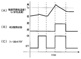
- FIG. 2 is a timing chart for explaining characteristic control in the first embodiment of the present invention. More specifically, FIG. 2 (A) shows a waveform representing the open / closed state of the WGV 40, and FIG. 2 (B) is ON when a predetermined fuel cut permission condition is satisfied during operation of the internal combustion engine 10. The waveform showing the success or failure of the fuel cut flag is shown. As shown in FIGS. 2A and 2B, when the fuel cut flag is turned ON, the WGV 40 is switched from a closed state (fully closed state) to an open state (for example, fully open state). Then, the WGV 40 is returned to the closed state when returning from the fuel cut when the fuel cut flag is turned off thereafter.
- a closed state fully closed state
- an open state for example, fully open state
- the throttle valve 20 is closed, so that the pressure in the cylinder becomes negative and oil rises easily. For this reason, during the fuel cut, a large amount of oil that becomes a binder when manganese oxide is deposited in the upstream catalyst 30 is easily contained in the exhaust gas discharged in the cylinder in the form of mist. . In addition, during the fuel cut in which fresh air with a high oxygen concentration flows through the upstream catalyst 30, the upstream catalyst 30 is in an oxidizing atmosphere, so that the deposition of manganese oxide is facilitated.
- the WGV 40 is in operation during a fuel cut in which a large amount of such oil mist is contained in the exhaust gas and a gas having high oxygen concentration (fresh air) flows through the upstream catalyst 30. Is controlled to be in an open state, the gas flow rate passing through the turbine 24b is reduced. Thereby, since the said vertical component of an exhaust gas flow can be made small, adhesion of the oil to the cell wall (inner wall surface) of the upstream catalyst 30 can be suppressed.
- oil adhesion to the upstream catalyst 30 that causes the accumulation of manganese oxide on the upstream catalyst 30 can be prevented, so that the manganese oxide during operation of the internal combustion engine 10 can be prevented. It is possible to satisfactorily suppress the clogging of the upstream catalyst 30 caused by the above.
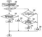
- FIG. 3 is a flowchart showing a control routine executed by the ECU 50 in order to realize the control of the first embodiment. Note that this routine is periodically executed at predetermined intervals while the internal combustion engine 10 is being started. In the routine shown in FIG. 3, it is first determined whether or not the fuel cut is being executed based on the success or failure of the fuel cut flag (step 100).
- the WGV 40 is controlled (or maintained) in the open state (step 102).
- the WGV 40 is controlled (or maintained) in the closed state (step 104).
- the control for switching the WGV 40 from the closed state to the open state is executed at the start of the fuel cut, and the WGV 40 is maintained in the open state during the fuel cut. . Then, at the time of return from the fuel cut, the WGV 40 that has been open until then is switched to the closed state.
- the vertical component of the exhaust gas flow can be reduced during the fuel cut. Therefore, the upstream catalyst 30 is clogged with manganese oxide by preventing oil from adhering to the upstream catalyst 30. Can be suppressed satisfactorily.
- the upstream catalyst 30 corresponds to the “exhaust purification catalyst” in the first invention
- the WGV 40 corresponds to the “bypass valve” in the first invention.
- the “bypass valve opening control means” according to the first aspect of the present invention is realized by the ECU 50 executing the processing of steps 100 and 102 described above.
- the “bypass valve closing control means” in the third aspect of the present invention is realized by the ECU 50 executing the processing of steps 100 and 104 described above.
- Embodiment 2 a second embodiment of the present invention will be described with reference to FIG. 4 and FIG.
- the system of the present embodiment can be realized by causing the ECU 50 to execute a routine shown in FIG. 5 described later instead of the routine shown in FIG. 3 using the hardware configuration shown in FIG.
- FIG. 4 is a timing chart for explaining characteristic control in Embodiment 2 of the present invention. More specifically, FIG. 4A shows a waveform representing a change in the catalyst atmosphere temperature T (or exhaust temperature), FIG. 4B shows a waveform representing the open / closed state of the WGV 40, and FIG. C) shows a waveform representing the success or failure of the fuel cut flag.
- the deposition of manganese oxide on the upstream catalyst 30 is promoted when the ambient temperature of the upstream catalyst 30 (hereinafter sometimes simply referred to as “catalyst ambient temperature T”) is high. Further, since the turbine rotational speed is lowered by opening the WGV 40, in order to sufficiently ensure the torque response when acceleration is required when returning from the fuel cut, even during the fuel cut is being executed. It can be said that the WGV 40 is desirably closed as much as possible.
- the WGV 40 is controlled to be in the open state when the fuel cut is being executed and the catalyst atmosphere temperature T is higher than the first predetermined value Ta.
- the catalyst atmosphere temperature T is higher than the first predetermined value Ta when the fuel cut flag is turned on (that is, at the start of fuel cut)
- the catalyst atmosphere temperature T during fuel cut is shown. Even if becomes equal to or less than the first predetermined value Ta, the example in which the WGV 40 is continuously opened when the fuel cut is in progress is shown.
- FIG. 5 is a flowchart showing a control routine executed by the ECU 50 in order to realize the control of the second embodiment.
- the same steps as those shown in FIG. 3 in the first embodiment are denoted by the same reference numerals, and the description thereof is omitted or simplified.
- the current catalyst atmosphere temperature T is estimated (calculated) based on the engine speed NE and the engine load factor KL calculated based on the intake air amount (step 200).
- the acquisition of the catalyst atmosphere temperature T is not limited to the estimation as described above, and a temperature sensor may be separately provided for the upstream catalyst 30 and may be detected by the temperature sensor.
- step 100 it is determined whether or not a fuel cut is being executed. As a result, if it is determined that the fuel cut is being performed, it is then determined whether or not the catalyst atmosphere temperature T acquired in step 200 is higher than a first predetermined value Ta (step 202). ).
- the first predetermined value Ta in step 202 is a value set in advance as a guideline for determining whether or not to open the WGV 40 during fuel cut in relation to the catalyst atmosphere temperature T.
- step 202 If it is determined in the above step 202 that the catalyst atmosphere temperature T is higher than the first predetermined value Ta, the WGV 40 is controlled (or maintained) in the open state (step 204). On the other hand, if it is determined in step 202 that the catalyst atmosphere temperature T is equal to or lower than the first predetermined value Ta, the WGV 40 is controlled (or maintained) in the closed state even while the fuel cut is being executed ( Step 206).
- the WGV 40 is switched from the closed state to the open state only when the fuel cut is being executed and the catalyst atmosphere temperature T is higher than the first predetermined value Ta.
- the catalyst atmosphere temperature T is higher than the first predetermined value Ta.
- the “catalyst temperature acquisition means” is realized by the ECU 50 executing the processing of step 200 described above.
- Embodiment 3 FIG. Next, Embodiment 3 of the present invention will be described with reference to FIG. 6 and FIG.
- the system of the present embodiment can be realized by causing the ECU 50 to execute a routine shown in FIG. 7 described later instead of the routine shown in FIG. 5 using the hardware configuration shown in FIG.
- FIG. 6 is a timing chart for explaining characteristic control in the third embodiment of the present invention. More specifically, FIG. 6A shows a waveform representing a change in the catalyst atmosphere temperature T (or exhaust temperature), FIG. 6B shows a waveform representing the open / closed state of the WGV 40, and FIG. C) shows a waveform representing the success or failure of the fuel cut flag.
- the catalyst atmosphere temperature T is less than the second predetermined value Tb ( ⁇ first predetermined value Ta) at the time of natural recovery from the fuel cut. If it is higher, control is performed to keep the WGV 40 in an open state until the catalyst atmosphere temperature T becomes equal to or lower than the second predetermined value Tb even after returning from the fuel cut.
- Tb second predetermined value
- the WGV 40 when the catalyst atmosphere temperature T is higher than the first predetermined value Ta when the fuel cut flag is turned on (that is, at the start of the fuel cut), the WGV 40 is used until the return from the fuel cut. Is continuously opened, and the WGV 40 is continuously opened until the catalyst atmosphere temperature T becomes equal to or lower than the second predetermined value Tb after returning from the fuel cut.
- FIG. 7 is a flowchart showing a control routine executed by the ECU 50 in order to realize the control of the third embodiment.
- the same steps as those shown in FIG. 5 in the second embodiment that is, steps 200, 100, and 202 to 206) are denoted by the same reference numerals, and the description thereof is omitted or simplified. .
- the idle flag is ON and the fuel cut return counter A is smaller than the predetermined value B.
- the idle flag is a flag for determining whether or not the accelerator pedal is in the idle position.
- the fuel cut return counter A is a counter that is counted from the fuel cut return start point, and is a value that is counted up using the timer function of the ECU 50 or the integrated intake air amount.
- the predetermined value B is a threshold value for determining whether or not the present time is at the time of return from the fuel cut or immediately after the return using the fuel cut return counter A.
- step 300 If it is determined in step 300 that the idle flag is ON and the fuel cut return counter A is smaller than the predetermined value B, the driver does not issue an accelerator request, And it can be judged that it is at the time of return from fuel cut or immediately after return. That is, in this case, it can be determined that the vehicle is in a natural return from a fuel cut or immediately after a natural return in which no accelerator request has been issued. In this case, it is then determined whether or not the catalyst atmosphere temperature T is higher than a second predetermined value Tb (step 302).
- the second predetermined value Tb in step 302 is a value set in advance as a guideline for determining whether or not to return the WGV 40 to the closed state after the natural recovery from the fuel cut in relation to the catalyst atmosphere temperature T. .
- the control for opening the WGV 40 is continued (step 304).
- the WGV 40 is controlled to be closed (step 306).
- step 300 determines whether the natural return from the fuel cut or not immediately after the natural return (for example, at the forced return from the fuel cut).
- the WGV 40 is controlled to be closed ( Or maintained) (step 306).
- the atmosphere of the upstream catalyst 30 is cooled to the second predetermined value Tb or less. Until the WGV 40 is opened, control is performed. Thereby, it is possible to further suppress the acceleration of the deposition of manganese oxide on the upstream catalyst 30 under a high temperature condition.
- the ECU 50 executes the series of processes of steps 100 and 300 to 306, thereby realizing the “first-return-opening control execution means” in the fourth aspect of the invention. Yes.
- Embodiment 4 FIG. Next, a fourth embodiment of the present invention will be described with reference to FIGS.
- the system of the present embodiment can be realized by causing the ECU 50 to execute a routine shown in FIG. 9 described later instead of the routine shown in FIG. 5 using the hardware configuration shown in FIG.
- FIG. 8 is a timing chart for explaining characteristic control in Embodiment 4 of the present invention. More specifically, FIG. 8A shows a waveform representing a change in the catalyst atmosphere temperature T (or exhaust temperature), and FIG. 8B shows that the air-fuel ratio is richer than the stoichiometric air-fuel ratio after fuel cut.
- FIG. 8C shows a waveform representing success / failure of the A / F rich operation flag after the fuel cut return that is turned ON when a predetermined execution condition for performing A / F rich operation under control is established.
- FIG. 8D shows a waveform representing the success or failure of the fuel cut flag.
- an A / F rich operation for the purpose of reducing NOx may be performed after the natural return from the fuel cut.
- the amount of manganese oxide contained in the exhaust gas increases. Therefore, in the present embodiment, as shown in FIG. 8, when the A / F rich operation flag after returning from the fuel cut is turned ON during the natural return from the fuel cut, the flag is set even after the fuel cut is returned. Control to open the WGV 40 is performed until is turned off.
- the catalyst atmosphere temperature T is higher than the first predetermined value Ta when the fuel cut flag is turned on (that is, at the start of the fuel cut)
- the WGV 40 is restored until the fuel cut is restored. Is continuously opened, and the WGV 40 is continuously opened during the A / F rich operation after returning from the fuel cut.
- FIG. 9 is a flowchart showing a control routine executed by the ECU 50 in order to realize the control of the fourth embodiment. 9, the same steps as those shown in FIG. 5 in the second embodiment (that is, steps 200, 100, and 202 to 206) are denoted by the same reference numerals, and the description thereof is omitted or simplified. .
- step 400 if it is determined in step 100 that the fuel cut is not being executed, it is then determined whether or not the idle flag is ON (step 400). As a result, when the idle flag is ON, that is, when the accelerator request is not issued, it is then determined whether or not the A / F rich operation flag after returning from the fuel cut is ON. (Step 402).
- step 402 If it is determined in step 402 above that the A / F rich operation flag after the fuel cut recovery is ON, the A / F rich operation is performed during the natural recovery when the accelerator request is not issued. It can be judged that there is. In this case, control for opening the WGV 40 is performed (step 404). On the other hand, if it is determined in step 402 that the A / F rich operation flag after fuel cut recovery is not ON (that is, the A / F rich operation after natural recovery is completed and the air-fuel ratio is calculated theoretically. When the stoichiometric operation (normal operation) performed as the air-fuel ratio is executed), the WGV 40 is controlled (or maintained) in the closed state (step 406).
- the WGV 40 is opened. Control is performed. Thereby, clogging of the upstream catalyst 30 by manganese oxide can further be suppressed.
- the WGV 40 when the normal stoichiometric operation is switched after the A / F rich operation is performed, the WGV 40 is switched from the open state to the closed state. Thereby, the responsiveness of the torque can be suppressed from being lowered while the clogging of the upstream catalyst 30 is suppressed by opening the WGV 40 during the A / F rich operation.
- control according to the fourth embodiment when the A / F rich operation is performed at the time of natural return from the fuel cut, control is performed to open the WGV 40 even after the fuel cut is returned. I have to. Further, the control according to the fourth embodiment may be implemented in combination with the control according to the third embodiment as appropriate.
- the ECU 50 controls the air-fuel ratio by controlling the fuel injection amount using the fuel injection valve 54 based on the output of the main A / F sensor 34 and the like.
- the “air-fuel ratio control means” according to the present invention executes the series of processes of steps 100 and 400 to 406, thereby realizing the “second post-return opening control execution means” according to the fifth invention. Yes.
- the “bypass valve closing control means” according to the sixth aspect of the present invention is realized by the ECU 50 executing the processing of steps 402 and 406 described above.
- the WGV 40 when the fuel cut is executed, the WGV 40 is controlled from the closed state to the open state, and in the first embodiment, when returning from the fuel cut (in other embodiments) In the embodiment, the WGV 40 is controlled from the open state to the closed state at a predetermined timing in the control of the second to fourth embodiments.
- the control mode of the bypass valve of the present invention in relation to the implementation of fuel cut is not limited to this. That is, when the bypass valve (WGV 40 or the like) is opened at a predetermined opening according to the operating state of the internal combustion engine at the start of the fuel cut, the opening of the bypass valve during the fuel cut is determined as the fuel cut.
- the catalyst temperature used for the control in the present invention is not limited to the catalyst atmosphere temperature T obtained by the above-described method, and is, for example, a value obtained by substituting the actually measured exhaust temperature, or the detected or estimated catalyst bed temperature. There may be.
Abstract
Description
尚、出願人は、本発明に関連するものとして、上記の文献を含めて、以下に記載する文献を認識している。
内燃機関の排気エネルギにより作動するタービンを排気通路に備えるターボ過給機と、
前記タービンよりも下流側の前記排気通路に配置され、排気ガスを浄化するための排気浄化触媒と、
前記タービンをバイパスする排気バイパス通路と、
前記排気バイパス通路の開閉を担うバイパス弁と、
前記内燃機関のフューエルカットが実行される場合に、当該フューエルカットの実行期間中の少なくとも一部の期間において、前記バイパス弁を開放する制御、または前記バイパス弁の開度を前記フューエルカットの開始時点の開度よりも大きくする制御を実行するバイパス弁開き制御手段と、
を備えることを特徴とする。
前記排気浄化触媒の温度を検出または推定する触媒温度取得手段を更に備え、
前記バイパス弁開き制御手段は、前記フューエルカットの実行中であって、前記排気浄化触媒の前記温度が第1所定値よりも高い場合に、前記バイパス弁を開放する前記制御、または前記バイパス弁の開度を前記フューエルカットの開始時点の開度よりも大きくする前記制御を実行することを特徴とする。
前記フューエルカットからの復帰時に、前記バイパス弁を閉塞する制御、または前記バイパス弁の開度を前記フューエルカットの実行中の開度よりも小さくする制御を実行するバイパス弁閉じ制御手段を更に備えることを特徴とする。
前記バイパス弁開き制御手段は、前記フューエルカットからの復帰時に、前記排気浄化触媒の前記温度が第2所定値よりも高い場合には、前記排気浄化触媒の前記温度が前記第2所定値以下になるまで、前記バイパス弁を開放する前記制御、または前記バイパス弁の開度を前記フューエルカットの開始時点の開度よりも大きくする前記制御を実施する第1復帰後開き制御実行手段を含むことを特徴とする。
前記内燃機関の空燃比を制御する空燃比制御手段を更に備え、
前記バイパス弁開き制御手段は、前記フューエルカットからの復帰時に、前記空燃比制御手段により前記空燃比を理論空燃比よりもリッチ側の空燃比とした状態でリッチ運転が行われる場合には、前記バイパス弁を開放する前記制御、または前記バイパス弁の開度を前記フューエルカットの開始時点の開度よりも大きくする前記制御を実施する第2復帰後開き制御実行手段を含むことを特徴とする。
前記第2復帰後開き制御実行手段は、前記フューエルカットからの復帰後に、前記リッチ運転から前記空燃比を理論空燃比とした状態でのストイキ運転に切り替えられた場合に、前記バイパス弁を閉塞する制御、または前記バイパス弁の開度を前記フューエルカットの実行中の開度よりも大きくする制御を実行するバイパス弁閉じ制御手段を含むことを特徴とする。
[システム構成の説明]
図1は、本発明の実施の形態1におけるターボ過給機付き内燃機関10のシステム構成を説明するための図である。本実施形態のシステムは、内燃機関10を備えている。内燃機関10は、ここでは一例として、ガソリンエンジンであるものとする。内燃機関10の吸気系は、吸気マニホールド12と、吸気マニホールド12に接続される吸気管(吸気通路)14とを備えている。空気は大気中から吸気管14に取り込まれ、吸気マニホールド12を介して各気筒の燃焼室に分配される。
ところで、使用燃料の性状如何(例えば、ガソリンの添加剤として、無鉛のMMT(メチルシクロペンタディエニールマンガントリカルボニル)などが使用されている場合)によっては、内燃機関10から排出される排気ガス中にマンガン酸化物が含まれる場合がある。このマンガン酸化物の上流触媒30への堆積が進行すると、上流触媒30に目詰まりが生じてしまうという問題がある。このようなマンガン酸化物による目詰まりの問題は、本実施形態の内燃機関10のようにターボ過給機付き内燃機関においてより顕著となる。これは、以下のような理由による。すなわち、マンガン酸化物による上流触媒30の目詰まりが生ずる主因の1つは、タービン24bの直下に配置された上流触媒30の入口において、排気ガスの流れのうち、上流触媒30の前端面に対して傾斜した成分(より具体的には、前端面の近傍のセル壁に対する垂直成分)が大きいことであると考えられる。また、ターボ過給機24を備える内燃機関10では、タービン24b通過後の排気ガスの流れが旋回流となるため、上流触媒30の入口において上記垂直成分が大きくなる。従って、ターボ過給機24を備える内燃機関10では、マンガン酸化物による上流触媒30の目詰まりが生じ易くなる。
以上説明したマンガン酸化物による上流触媒30の目詰まりを抑制するためには、排気ガスの流れの上記垂直成分が大きくなることを防止するためにWGV40を開状態にすることが有効である。しかしながら、WGV40を開くことによるタービン回転数の低下によって内燃機関10に加速が要求された場合のトルクの応答性の低下等を招くため、内燃機関10の運転中にWGV40を常時開状態とすることは好ましくない。そこで、本実施形態では、以下の図2に示すような制御を行うこととした。
図2(A)および(B)に示すように、フューエルカットフラグがONとされた場合には、WGV40を閉状態(全閉状態)から開状態(例えば、全開状態)に切り替えるようにした。そして、その後にフューエルカットフラグがOFFとされたことに伴うフューエルカットからの復帰時に、WGV40を閉状態に戻すようにした。
図3に示すルーチンでは、先ず、フューエルカットフラグの成否に基づいてフューエルカットの実行中であるか否かが判定される(ステップ100)。
また、ECU50が上記ステップ100および104の処理を実行することにより前記
第3の発明における「バイパス弁閉じ制御手段」が実現されている。
次に、図4および図5を参照して、本発明の実施の形態2について説明する。
本実施形態のシステムは、図1に示すハードウェア構成を用いて、ECU50に図3に示すルーチンに代えて後述の図5に示すルーチンを実行させることにより実現することができるものである。
次に、図6および図7を参照して、本発明の実施の形態3について説明する。
本実施形態のシステムは、図1に示すハードウェア構成を用いて、ECU50に図5に示すルーチンに代えて後述の図7に示すルーチンを実行させることにより実現することができるものである。
次に、図8および図9を参照して、本発明の実施の形態4について説明する。
本実施形態のシステムは、図1に示すハードウェア構成を用いて、ECU50に図5に示すルーチンに代えて後述の図9に示すルーチンを実行させることにより実現することができるものである。
また、ECU50が上記ステップ402および406の処理を実行することにより前記第6の発明における「バイパス弁閉じ制御手段」が実現されている。
14 吸気管
18 エアフローメータ
20 スロットルバルブ
24 ターボ過給機
24a コンプレッサ
24b タービン
26 排気管
30 上流触媒(SC)
32 下流触媒(UFC)
34 メイン空燃比センサ
36 サブO2センサ
38 排気バイパス通路
40 ウェイストゲートバルブ(WGV)
42 WGVのアクチュエータ
44 空気配管
46 電磁弁
48 ロッド
50 ECU(Electronic Control Unit)
52 クランク角センサ
54 燃料噴射弁
Claims (6)
- 内燃機関の排気エネルギにより作動するタービンを排気通路に備えるターボ過給機と、
前記タービンよりも下流側の前記排気通路に配置され、排気ガスを浄化するための排気浄化触媒と、
前記タービンをバイパスする排気バイパス通路と、
前記排気バイパス通路の開閉を担うバイパス弁と、
前記内燃機関のフューエルカットが実行される場合に、当該フューエルカットの実行期間中の少なくとも一部の期間において、前記バイパス弁を開放する制御、または前記バイパス弁の開度を前記フューエルカットの開始時点の開度よりも大きくする制御を実行するバイパス弁開き制御手段と、
を備えることを特徴とするターボ過給機付き内燃機関。 - 前記排気浄化触媒の温度を検出または推定する触媒温度取得手段を更に備え、
前記バイパス弁開き制御手段は、前記フューエルカットの実行中であって、前記排気浄化触媒の前記温度が第1所定値よりも高い場合に、前記バイパス弁を開放する前記制御、または前記バイパス弁の開度を前記フューエルカットの開始時点の開度よりも大きくする前記制御を実行することを特徴とする請求項1記載のターボ過給機付き内燃機関。 - 前記フューエルカットからの復帰時に、前記バイパス弁を閉塞する制御、または前記バイパス弁の開度を前記フューエルカットの実行中の開度よりも小さくする制御を実行するバイパス弁閉じ制御手段を更に備えることを特徴とする請求項1または2記載のターボ過給機付き内燃機関。
- 前記バイパス弁開き制御手段は、前記フューエルカットからの復帰時に、前記排気浄化触媒の前記温度が第2所定値よりも高い場合には、前記排気浄化触媒の前記温度が前記第2所定値以下になるまで、前記バイパス弁を開放する前記制御、または前記バイパス弁の開度を前記フューエルカットの開始時点の開度よりも大きくする前記制御を実施する第1復帰後開き制御実行手段を含むことを特徴とする請求項2記載のターボ過給機付き内燃機関。
- 前記内燃機関の空燃比を制御する空燃比制御手段を更に備え、
前記バイパス弁開き制御手段は、前記フューエルカットからの復帰時に、前記空燃比制御手段により前記空燃比を理論空燃比よりもリッチ側の空燃比とした状態でリッチ運転が行われる場合には、前記バイパス弁を開放する前記制御、または前記バイパス弁の開度を前記フューエルカットの開始時点の開度よりも大きくする前記制御を実施する第2復帰後開き制御実行手段を含むことを特徴とする請求項2または4記載のターボ過給機付き内燃機関。 - 前記第2復帰後開き制御実行手段は、前記フューエルカットからの復帰後に、前記リッチ運転から前記空燃比を理論空燃比とした状態でのストイキ運転に切り替えられた場合に、前記バイパス弁を閉塞する制御、または前記バイパス弁の開度を前記フューエルカットの実行中の開度よりも大きくする制御を実行するバイパス弁閉じ制御手段を含むことを特徴とする請求項5記載のターボ過給機付き内燃機関。
Priority Applications (5)
| Application Number | Priority Date | Filing Date | Title |
|---|---|---|---|
| US13/383,564 US8607565B2 (en) | 2010-09-29 | 2010-09-29 | Internal combustion engine with turbocharger |
| PCT/JP2010/066924 WO2012042609A1 (ja) | 2010-09-29 | 2010-09-29 | ターボ過給機付き内燃機関 |
| CN201080042844.2A CN102549249B (zh) | 2010-09-29 | 2010-09-29 | 带涡轮增压器的内燃机 |
| EP10853386.0A EP2520783B1 (en) | 2010-09-29 | 2010-09-29 | Internal combustion engine with turbocharger |
| JP2011552656A JP5246350B2 (ja) | 2010-09-29 | 2010-09-29 | ターボ過給機付き内燃機関 |
Applications Claiming Priority (1)
| Application Number | Priority Date | Filing Date | Title |
|---|---|---|---|
| PCT/JP2010/066924 WO2012042609A1 (ja) | 2010-09-29 | 2010-09-29 | ターボ過給機付き内燃機関 |
Publications (1)
| Publication Number | Publication Date |
|---|---|
| WO2012042609A1 true WO2012042609A1 (ja) | 2012-04-05 |
Family
ID=45892113
Family Applications (1)
| Application Number | Title | Priority Date | Filing Date |
|---|---|---|---|
| PCT/JP2010/066924 WO2012042609A1 (ja) | 2010-09-29 | 2010-09-29 | ターボ過給機付き内燃機関 |
Country Status (5)
| Country | Link |
|---|---|
| US (1) | US8607565B2 (ja) |
| EP (1) | EP2520783B1 (ja) |
| JP (1) | JP5246350B2 (ja) |
| CN (1) | CN102549249B (ja) |
| WO (1) | WO2012042609A1 (ja) |
Cited By (6)
| Publication number | Priority date | Publication date | Assignee | Title |
|---|---|---|---|---|
| JP2014092045A (ja) * | 2012-11-01 | 2014-05-19 | Toyota Motor Corp | 内燃機関の制御装置 |
| JP2014227954A (ja) * | 2013-05-23 | 2014-12-08 | 三菱自動車工業株式会社 | エンジンの制御装置 |
| JP2017096158A (ja) * | 2015-11-24 | 2017-06-01 | トヨタ自動車株式会社 | 内燃機関の制御装置 |
| JP2020133624A (ja) * | 2019-02-18 | 2020-08-31 | トヨタ自動車株式会社 | 車載内燃機関の制御装置 |
| US10830167B2 (en) | 2017-05-19 | 2020-11-10 | Toyota Jidosha Kabushiki Kaisha | Exhaust gas purification system for an internal combustion engine |
| US10968804B2 (en) | 2018-08-29 | 2021-04-06 | Toyota Jidosha Kabushiki Kaisha | Controller and control method for internal combustion engine |
Families Citing this family (7)
| Publication number | Priority date | Publication date | Assignee | Title |
|---|---|---|---|---|
| US9527498B2 (en) * | 2012-08-29 | 2016-12-27 | Ford Global Technologies, Llc | Method to limit temperature increase in a catalyst and detect a restricted exhaust path in a vehicle |
| AT514577B1 (de) | 2013-10-09 | 2015-02-15 | Ge Jenbacher Gmbh & Co Og | Verfahren zum Betreiben einer mit einem Generator gekoppelten Brennkraftmaschine |
| WO2015068504A1 (ja) * | 2013-11-07 | 2015-05-14 | 本田技研工業株式会社 | 排気構造 |
| US9382829B2 (en) | 2014-10-21 | 2016-07-05 | Toyota Motor Engineering & Manufacturing North America, Inc. | Bypass exhaust pathway to allow gases to bypass the start catalyst of a vehicle |
| JP6296045B2 (ja) * | 2015-12-08 | 2018-03-20 | トヨタ自動車株式会社 | 内燃機関の制御装置 |
| DE102018216589A1 (de) * | 2018-09-27 | 2020-04-02 | Bayerische Motoren Werke Aktiengesellschaft | Verfahren zum Betreiben einer fremd gezündeten Brennkraftmaschine |
| CN112752901A (zh) * | 2018-10-01 | 2021-05-04 | 沃尔沃卡车集团 | 用于控制内燃发动机的方法、计算机程序、计算机可读介质、控制单元、内燃发动机和车辆 |
Citations (5)
| Publication number | Priority date | Publication date | Assignee | Title |
|---|---|---|---|---|
| JP2000265893A (ja) * | 1999-03-15 | 2000-09-26 | Fuji Heavy Ind Ltd | 多気筒エンジン |
| JP2006152878A (ja) * | 2004-11-26 | 2006-06-15 | Denso Corp | 過給機付きエンジンの制御装置 |
| JP2007332849A (ja) * | 2006-06-14 | 2007-12-27 | Hino Motors Ltd | 排気浄化装置 |
| JP2007332872A (ja) * | 2006-06-15 | 2007-12-27 | Toyota Motor Corp | 過給機付内燃機関の排気整流装置 |
| JP2009275527A (ja) * | 2008-05-12 | 2009-11-26 | Toyota Motor Corp | 過給機付内燃機関の排気浄化装置 |
Family Cites Families (12)
| Publication number | Priority date | Publication date | Assignee | Title |
|---|---|---|---|---|
| JPH1162602A (ja) | 1997-08-09 | 1999-03-05 | Toyota Motor Corp | 可変容量型ターボチャージャの制御装置 |
| DE10031924A1 (de) * | 2000-06-30 | 2002-01-10 | Bosch Gmbh Robert | Überprüfung von Katalysatorheizmassnahmen bei Brennkraftmaschinen |
| JP3593962B2 (ja) | 2000-08-24 | 2004-11-24 | トヨタ自動車株式会社 | 内燃機関の排気浄化装置 |
| JP3716799B2 (ja) * | 2002-02-20 | 2005-11-16 | トヨタ自動車株式会社 | 機関一時停止を伴う車輌用内燃機関の運転方法 |
| DE102004009791A1 (de) * | 2004-02-28 | 2005-09-22 | Daimlerchrysler Ag | Verfahren zur beschleunigten Erwärmung einer Reinigungseinrichtung im Abgasstrang einer Brennkraftmaschine und Brennkraftmaschine |
| JP2008157139A (ja) * | 2006-12-25 | 2008-07-10 | Toyota Motor Corp | 過給機付内燃機関 |
| JP5037263B2 (ja) * | 2007-03-02 | 2012-09-26 | 本田技研工業株式会社 | 内燃機関の制御装置 |
| DE102007017413A1 (de) * | 2007-04-13 | 2008-10-16 | Daimler Ag | Verfahren zum Betreiben einer Brennkraftmaschine im Schiebebetrieb mit Kraftstoffabschaltung |
| CN102365434B (zh) * | 2009-04-02 | 2013-12-25 | 丰田自动车株式会社 | 排气净化催化剂的升温系统 |
| US8086390B2 (en) * | 2009-10-30 | 2011-12-27 | GM Global Technology Operations LLC | Pumping loss reduction systems and methods |
| US8347611B2 (en) * | 2009-12-23 | 2013-01-08 | Ford Global Technologies, Llc | Methods and systems for emission system control |
| EP2615281A4 (en) * | 2010-12-07 | 2014-05-14 | Toyota Motor Co Ltd | CONTROL DEVICE FOR INTERNAL COMBUSTION ENGINE |
-
2010
- 2010-09-29 WO PCT/JP2010/066924 patent/WO2012042609A1/ja active Application Filing
- 2010-09-29 JP JP2011552656A patent/JP5246350B2/ja not_active Expired - Fee Related
- 2010-09-29 CN CN201080042844.2A patent/CN102549249B/zh not_active Expired - Fee Related
- 2010-09-29 US US13/383,564 patent/US8607565B2/en active Active
- 2010-09-29 EP EP10853386.0A patent/EP2520783B1/en not_active Not-in-force
Patent Citations (5)
| Publication number | Priority date | Publication date | Assignee | Title |
|---|---|---|---|---|
| JP2000265893A (ja) * | 1999-03-15 | 2000-09-26 | Fuji Heavy Ind Ltd | 多気筒エンジン |
| JP2006152878A (ja) * | 2004-11-26 | 2006-06-15 | Denso Corp | 過給機付きエンジンの制御装置 |
| JP2007332849A (ja) * | 2006-06-14 | 2007-12-27 | Hino Motors Ltd | 排気浄化装置 |
| JP2007332872A (ja) * | 2006-06-15 | 2007-12-27 | Toyota Motor Corp | 過給機付内燃機関の排気整流装置 |
| JP2009275527A (ja) * | 2008-05-12 | 2009-11-26 | Toyota Motor Corp | 過給機付内燃機関の排気浄化装置 |
Non-Patent Citations (1)
| Title |
|---|
| See also references of EP2520783A4 * |
Cited By (8)
| Publication number | Priority date | Publication date | Assignee | Title |
|---|---|---|---|---|
| JP2014092045A (ja) * | 2012-11-01 | 2014-05-19 | Toyota Motor Corp | 内燃機関の制御装置 |
| JP2014227954A (ja) * | 2013-05-23 | 2014-12-08 | 三菱自動車工業株式会社 | エンジンの制御装置 |
| JP2017096158A (ja) * | 2015-11-24 | 2017-06-01 | トヨタ自動車株式会社 | 内燃機関の制御装置 |
| US10458348B2 (en) | 2015-11-24 | 2019-10-29 | Toyota Jidosha Kabushiki Kaisha | Control apparatus for an internal combustion engine |
| US10830167B2 (en) | 2017-05-19 | 2020-11-10 | Toyota Jidosha Kabushiki Kaisha | Exhaust gas purification system for an internal combustion engine |
| DE102018207915B4 (de) | 2017-05-19 | 2024-03-14 | Toyota Jidosha Kabushiki Kaisha | Abgasreinigungssystem für einen Verbrennungsmotor |
| US10968804B2 (en) | 2018-08-29 | 2021-04-06 | Toyota Jidosha Kabushiki Kaisha | Controller and control method for internal combustion engine |
| JP2020133624A (ja) * | 2019-02-18 | 2020-08-31 | トヨタ自動車株式会社 | 車載内燃機関の制御装置 |
Also Published As
| Publication number | Publication date |
|---|---|
| CN102549249B (zh) | 2014-02-19 |
| EP2520783A1 (en) | 2012-11-07 |
| CN102549249A (zh) | 2012-07-04 |
| US20120137677A1 (en) | 2012-06-07 |
| JPWO2012042609A1 (ja) | 2014-02-03 |
| EP2520783A4 (en) | 2014-05-14 |
| JP5246350B2 (ja) | 2013-07-24 |
| US8607565B2 (en) | 2013-12-17 |
| EP2520783B1 (en) | 2016-01-06 |
Similar Documents
| Publication | Publication Date | Title |
|---|---|---|
| JP5246350B2 (ja) | ターボ過給機付き内燃機関 | |
| US7895838B2 (en) | Exhaust gas recirculation apparatus of an internal combustion engine and control method thereof | |
| JP6540682B2 (ja) | 内燃機関の制御装置及び内燃機関の制御装置の異常診断システム | |
| CN103732902A (zh) | 固定比率egr系统 | |
| JP5187123B2 (ja) | 内燃機関の制御装置 | |
| JP5169439B2 (ja) | 内燃機関制御装置及び内燃機関制御システム | |
| JP2005240756A (ja) | エンジンの制御装置 | |
| WO2012086002A1 (ja) | 過給機付き内燃機関の制御装置 | |
| WO2012157108A1 (ja) | 内燃機関の制御装置 | |
| EP1925798B1 (en) | Exhaust gas purifying device for an internal combustion engine | |
| EP2211044B1 (en) | EGR controller and EGR control method for internal combustion engine | |
| US7418334B2 (en) | Method for operating an internal combustion engine comprising an exhaust gas purification system | |
| JP2007303437A (ja) | 内燃機関の制御装置 | |
| JP4613812B2 (ja) | ディーゼルエンジン | |
| JP2008008241A (ja) | エンジンの制御装置 | |
| EP2395223B1 (en) | Internal combustion engine exhaust purifying device and exhaust purifying method | |
| JP2010159672A (ja) | エンジンの排気浄化装置 | |
| JP4736978B2 (ja) | 内燃機関の排気還流装置 | |
| JP4506324B2 (ja) | 過給機付き車両用内燃機関のegrシステム | |
| JP4468287B2 (ja) | 内燃機関の排ガス浄化装置 | |
| JP4501761B2 (ja) | 内燃機関の制御装置 | |
| JP2008038624A (ja) | 内燃機関の排気浄化装置、及び方法 | |
| JP2007303355A (ja) | 内燃機関のegr制御装置 | |
| JP2008051042A (ja) | 過給機付きエンジンの制御装置 | |
| JP5074717B2 (ja) | 内燃機関の燃料噴射制御装置 |
Legal Events
| Date | Code | Title | Description |
|---|---|---|---|
| WWE | Wipo information: entry into national phase |
Ref document number: 201080042844.2 Country of ref document: CN |
|
| WWE | Wipo information: entry into national phase |
Ref document number: 2011552656 Country of ref document: JP |
|
| WWE | Wipo information: entry into national phase |
Ref document number: 2010853386 Country of ref document: EP |
|
| WWE | Wipo information: entry into national phase |
Ref document number: 13383564 Country of ref document: US |
|
| 121 | Ep: the epo has been informed by wipo that ep was designated in this application |
Ref document number: 10853386 Country of ref document: EP Kind code of ref document: A1 |
|
| NENP | Non-entry into the national phase |
Ref country code: DE |