WO2012029774A1 - モータ制御装置及びこれを搭載した移動体 - Google Patents
モータ制御装置及びこれを搭載した移動体 Download PDFInfo
- Publication number
- WO2012029774A1 WO2012029774A1 PCT/JP2011/069596 JP2011069596W WO2012029774A1 WO 2012029774 A1 WO2012029774 A1 WO 2012029774A1 JP 2011069596 W JP2011069596 W JP 2011069596W WO 2012029774 A1 WO2012029774 A1 WO 2012029774A1
- Authority
- WO
- WIPO (PCT)
- Prior art keywords
- unit
- motor
- power
- power line
- terminal
- Prior art date
- Legal status (The legal status is an assumption and is not a legal conclusion. Google has not performed a legal analysis and makes no representation as to the accuracy of the status listed.)
- Ceased
Links
Images











Classifications
-
- B—PERFORMING OPERATIONS; TRANSPORTING
- B60—VEHICLES IN GENERAL
- B60L—PROPULSION OF ELECTRICALLY-PROPELLED VEHICLES; SUPPLYING ELECTRIC POWER FOR AUXILIARY EQUIPMENT OF ELECTRICALLY-PROPELLED VEHICLES; ELECTRODYNAMIC BRAKE SYSTEMS FOR VEHICLES IN GENERAL; MAGNETIC SUSPENSION OR LEVITATION FOR VEHICLES; MONITORING OPERATING VARIABLES OF ELECTRICALLY-PROPELLED VEHICLES; ELECTRIC SAFETY DEVICES FOR ELECTRICALLY-PROPELLED VEHICLES
- B60L3/00—Electric devices on electrically-propelled vehicles for safety purposes; Monitoring operating variables, e.g. speed, deceleration or energy consumption
- B60L3/0023—Detecting, eliminating, remedying or compensating for drive train abnormalities, e.g. failures within the drive train
- B60L3/003—Detecting, eliminating, remedying or compensating for drive train abnormalities, e.g. failures within the drive train relating to inverters
-
- B—PERFORMING OPERATIONS; TRANSPORTING
- B60—VEHICLES IN GENERAL
- B60L—PROPULSION OF ELECTRICALLY-PROPELLED VEHICLES; SUPPLYING ELECTRIC POWER FOR AUXILIARY EQUIPMENT OF ELECTRICALLY-PROPELLED VEHICLES; ELECTRODYNAMIC BRAKE SYSTEMS FOR VEHICLES IN GENERAL; MAGNETIC SUSPENSION OR LEVITATION FOR VEHICLES; MONITORING OPERATING VARIABLES OF ELECTRICALLY-PROPELLED VEHICLES; ELECTRIC SAFETY DEVICES FOR ELECTRICALLY-PROPELLED VEHICLES
- B60L50/00—Electric propulsion with power supplied within the vehicle
- B60L50/50—Electric propulsion with power supplied within the vehicle using propulsion power supplied by batteries or fuel cells
- B60L50/51—Electric propulsion with power supplied within the vehicle using propulsion power supplied by batteries or fuel cells characterised by AC-motors
-
- B—PERFORMING OPERATIONS; TRANSPORTING
- B60—VEHICLES IN GENERAL
- B60L—PROPULSION OF ELECTRICALLY-PROPELLED VEHICLES; SUPPLYING ELECTRIC POWER FOR AUXILIARY EQUIPMENT OF ELECTRICALLY-PROPELLED VEHICLES; ELECTRODYNAMIC BRAKE SYSTEMS FOR VEHICLES IN GENERAL; MAGNETIC SUSPENSION OR LEVITATION FOR VEHICLES; MONITORING OPERATING VARIABLES OF ELECTRICALLY-PROPELLED VEHICLES; ELECTRIC SAFETY DEVICES FOR ELECTRICALLY-PROPELLED VEHICLES
- B60L50/00—Electric propulsion with power supplied within the vehicle
- B60L50/50—Electric propulsion with power supplied within the vehicle using propulsion power supplied by batteries or fuel cells
- B60L50/60—Electric propulsion with power supplied within the vehicle using propulsion power supplied by batteries or fuel cells using power supplied by batteries
- B60L50/66—Arrangements of batteries
-
- B—PERFORMING OPERATIONS; TRANSPORTING
- B60—VEHICLES IN GENERAL
- B60L—PROPULSION OF ELECTRICALLY-PROPELLED VEHICLES; SUPPLYING ELECTRIC POWER FOR AUXILIARY EQUIPMENT OF ELECTRICALLY-PROPELLED VEHICLES; ELECTRODYNAMIC BRAKE SYSTEMS FOR VEHICLES IN GENERAL; MAGNETIC SUSPENSION OR LEVITATION FOR VEHICLES; MONITORING OPERATING VARIABLES OF ELECTRICALLY-PROPELLED VEHICLES; ELECTRIC SAFETY DEVICES FOR ELECTRICALLY-PROPELLED VEHICLES
- B60L2200/00—Type of vehicles
- B60L2200/12—Bikes
-
- B—PERFORMING OPERATIONS; TRANSPORTING
- B60—VEHICLES IN GENERAL
- B60L—PROPULSION OF ELECTRICALLY-PROPELLED VEHICLES; SUPPLYING ELECTRIC POWER FOR AUXILIARY EQUIPMENT OF ELECTRICALLY-PROPELLED VEHICLES; ELECTRODYNAMIC BRAKE SYSTEMS FOR VEHICLES IN GENERAL; MAGNETIC SUSPENSION OR LEVITATION FOR VEHICLES; MONITORING OPERATING VARIABLES OF ELECTRICALLY-PROPELLED VEHICLES; ELECTRIC SAFETY DEVICES FOR ELECTRICALLY-PROPELLED VEHICLES
- B60L2250/00—Driver interactions
- B60L2250/10—Driver interactions by alarm
-
- B—PERFORMING OPERATIONS; TRANSPORTING
- B60—VEHICLES IN GENERAL
- B60L—PROPULSION OF ELECTRICALLY-PROPELLED VEHICLES; SUPPLYING ELECTRIC POWER FOR AUXILIARY EQUIPMENT OF ELECTRICALLY-PROPELLED VEHICLES; ELECTRODYNAMIC BRAKE SYSTEMS FOR VEHICLES IN GENERAL; MAGNETIC SUSPENSION OR LEVITATION FOR VEHICLES; MONITORING OPERATING VARIABLES OF ELECTRICALLY-PROPELLED VEHICLES; ELECTRIC SAFETY DEVICES FOR ELECTRICALLY-PROPELLED VEHICLES
- B60L2250/00—Driver interactions
- B60L2250/16—Driver interactions by display
-
- Y—GENERAL TAGGING OF NEW TECHNOLOGICAL DEVELOPMENTS; GENERAL TAGGING OF CROSS-SECTIONAL TECHNOLOGIES SPANNING OVER SEVERAL SECTIONS OF THE IPC; TECHNICAL SUBJECTS COVERED BY FORMER USPC CROSS-REFERENCE ART COLLECTIONS [XRACs] AND DIGESTS
- Y02—TECHNOLOGIES OR APPLICATIONS FOR MITIGATION OR ADAPTATION AGAINST CLIMATE CHANGE
- Y02T—CLIMATE CHANGE MITIGATION TECHNOLOGIES RELATED TO TRANSPORTATION
- Y02T10/00—Road transport of goods or passengers
- Y02T10/60—Other road transportation technologies with climate change mitigation effect
- Y02T10/70—Energy storage systems for electromobility, e.g. batteries
Definitions
- the present invention relates to a motor control device including an inverter circuit.
- the present invention also relates to a moving object including an electric vehicle equipped with this motor control device.
- an inverter circuit is often used for a motor control device applied to an electric vehicle or the like.
- the inverter circuit has a function of converting DC power output from the power supply unit into AC power necessary for driving the motor.
- the inverter circuit includes a switching element composed of an FET (Field Effect Transistor) or the like, and converts the DC power into AC power by controlling the switching element and repeating conduction and interruption of current.
- FET Field Effect Transistor
- the inverter circuit when controlling a three-phase motor, corresponds to each of the upper arm side (high voltage side) and the lower arm side (low voltage side) of the three phases (U phase, V phase, W phase). Some have a total of six switching elements. The inverter circuit controls these switching elements to switch the direction of the three-phase current and gives a desired driving force to the motor.
- Such an inverter circuit is connected to an input power line wired between the power supply unit and an output power line wired between the motor. If these wirings are connected by mistake, depending on the connection state, there is a risk that the power supply unit will be short-circuited, or the switching elements of the inverter circuit may be damaged. Then, prevention of the incorrect connection of the power supply part with respect to an inverter circuit is examined, and the example can be seen in patent document 1.
- the power conversion device described in Patent Document 1 constitutes a bridge circuit in which a plurality of series connection circuit portions in which switching elements and shunt resistors of upper and lower arms of an inverter circuit are connected in series are connected in parallel.
- a method is disclosed in which an erroneous connection is detected by determining a threshold value based on whether or not the current flowing through the shunt resistor is 0 when all the lower arm sides are simultaneously conducted.
- the power conversion device described in Patent Document 1 conducts current to the switching element of the inverter circuit in a state where the power supply device is connected to the output terminal to which the load device (for example, a motor) is connected, as in normal operation. An incorrect connection is detected. Thereby, when the positive / negative power line for input from a power supply device is connected to each of the input terminal and output terminal of a power converter device, there exists a possibility that a switching element may be damaged.
- the power conversion device described in Patent Document 1 discloses a method of detecting an erroneous connection when a power supply device is connected to an output terminal.
- the power conversion device described in Patent Document 1 discloses a method of detecting an erroneous connection when a power supply device is connected to an output terminal.
- no consideration is given to detection of erroneous connection when the positive and negative power lines for input from the power supply device are connected to the input terminal and the output terminal of the power converter, respectively.
- the present invention has been made in view of the above points, and before driving the motor, the power supply unit and the motor are erroneously connected to the inverter circuit without conducting current to the switching element of the inverter circuit as in normal operation. It is an object of the present invention to provide a motor control device that can be grasped and can prevent breakage of a switching element of an inverter circuit due to the erroneous connection. It is another object of the present invention to provide a moving body including an electric vehicle with improved reliability by mounting such a motor control device.
- a motor control device includes a capacitor that smoothes fluctuations of input DC power, a voltage detection unit that detects the voltage of the capacitor, and converts DC power into AC power.
- a power line and an output power line for outputting power to the motor are individually connected to a terminal unit having a plurality of terminals
- the precharge circuit unit is controlled to charge the capacitor
- the voltage detection unit detects A control unit for determining a connection state between the input power line and the output power line in the terminal unit based on the voltage of the capacitor. It was and.
- the motor control device is mounted on a moving body including an electric vehicle.
- FIG. 1 is a side view showing an example of an electric vehicle that is a moving body equipped with a motor control device according to a first embodiment of the present invention. It is a block diagram which shows the structure of the electric vehicle of FIG. It is a schematic block diagram which shows the motor control apparatus periphery of FIG.
- FIG. 4 is a top view of an inverter unit of the motor control device shown in FIG. 3. It is a table
- FIG. 5 is a top view of the same inverter unit as in FIG. 4 and shows a connection state of erroneous connection example 1; FIG.
- FIG. 4 is a schematic configuration diagram showing the periphery of a motor control device similar to FIG. 3, and shows a connection state of erroneous connection example 1; 10 is a table showing all connection states of erroneous connection example 1.
- FIG. 9 is a top view of the same inverter unit as in FIG. 4 and shows a connection state of erroneous connection example 2.
- FIG. 9 is a schematic configuration diagram showing the periphery of a motor control device similar to that in FIG. 10 is a table showing all connection states of erroneous connection example 2.
- FIG. 9 is a top view of the same inverter unit as FIG. 4 and shows a connection state of erroneous connection example 3.
- FIG. 9 is a top view of the same inverter unit as FIG. 4 and shows a connection state of erroneous connection example 3.
- FIG. 9 is a schematic configuration diagram showing the periphery of a motor control device similar to FIG. 3, and shows a connection state of erroneous connection example 3. It is a table
- FIG. FIG. 9 is a top view of the same inverter unit as in FIG. 4 and shows a connection state of erroneous connection example 4;
- FIG. 9 is a schematic configuration diagram showing the periphery of a motor control device similar to FIG. 3, and shows a connection state of an erroneous connection example 4. It is a table
- FIG. 9 is a top view of the same inverter unit as in FIG.
- FIG. 9 is a schematic configuration diagram showing the periphery of a motor control device similar to FIG. 3, and shows a connection state of erroneous connection example 5.
- 10 is a table showing all connection states of erroneous connection example 5.
- FIG. 9 is a top view of the same inverter unit as in FIG. 4 and shows a connection state of erroneous connection example 6.
- FIG. 9 is a schematic configuration diagram showing the periphery of a motor control device similar to FIG. 3, and shows a connection state of erroneous connection example 6. It is a table
- FIG. 25 is a top view of the inverter unit of the motor control device shown in FIG. 25 and shows the connection state of erroneous connection example 7.
- FIG. 26 is a schematic configuration diagram showing the periphery of a motor control device similar to FIG. 25, and shows a connection state of an erroneous connection example 7; It is a table
- FIG. 1 is a side view showing an example of an electric vehicle equipped with a motor control device
- FIG. 2 is a block diagram showing the configuration of the electric vehicle.
- the electric vehicle 1 is an electric motorcycle having a front wheel 2 and a rear wheel 3 as shown in FIG. 1, and more specifically, an electric motorcycle.
- the electric vehicle 1 includes a main frame 4 and a swing arm 5 as a main frame.
- the front end of the main frame 4 is bent upward, and the front wheel 2 and the handle 6 are supported by the front end so as to be steerable.
- the handle 6 is provided with a throttle 7 used for acceleration / deceleration of the electric vehicle 1 and a brake lever 8 used for braking.
- a display unit 9 is provided at the center of the left and right handles 6.
- the display unit 9 displays driving information such as power ON / OFF and travel speed, and also functions as a notification unit that notifies the user of abnormality information using an error code or the like when a failure occurs in the electric vehicle 1.
- a seat 10 on which a user sits down and a battery housing portion 11 are provided at the rear end side of the main frame 4 and at a substantially central portion in the front-rear direction of the electric vehicle 1.
- the battery accommodating portion 11 is provided below the seat 10 and can accommodate the battery 12 therein.
- the seat 10 also serves as a lid for the battery housing portion 11 and is attached to the battery housing portion 11 so as to be openable and closable.
- a luggage platform 13 is provided behind the seat 10 of the main frame 4 and above the rear wheel 3.
- the swing arm 5 extends rearward from the lower part of the seat 10 and the battery accommodating part 11 at the rear part of the main frame 4.
- the rear wheel 3 is supported at the rear end of the swing arm 5.
- the rear wheel 3 is a drive wheel and includes a motor 20 that drives the rear wheel 3 between the rear wheel 3 and the swing arm 5.
- the swing arm 5 supports the motor 20 and the rear wheels 3 with their rotation axes horizontal.
- a suspension unit 14 is provided to suspend the motor 20 and the rear wheel 3 from the upper portion of the motor 20 portion of the swing arm 5 toward the upper luggage platform 13.
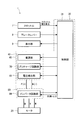
- the electric vehicle 1 is provided with a motor control device 30 as shown in FIG. 2 for controlling the operation of the entire vehicle.
- the motor control device 30 includes a control unit 31, a power supply unit 40, and an inverter unit 50.
- the power supply unit 40 includes a power supply unit 60, a precharge circuit unit 70, and a voltage detection unit 41, and the inverter unit 50 includes an inverter circuit unit 80.
- the control unit 31 is configured by a general microcomputer, and functions as a processor that controls a series of operations related to running of the electric vehicle 1 based on programs and data stored and input in the microcomputer.
- the control unit 31 sets a target torque for the motor 20 according to the degree of opening of the throttle 7 obtained from the throttle 7 operated by the user. Then, the control unit 31 controls the inverter circuit unit 80 with respect to the power supplied from the power supply unit 60 to adjust the current and voltage to be sent to the motor 20 to drive the motor 20.
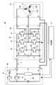
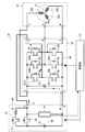
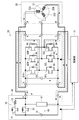
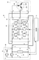
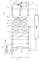
- FIGS. 3 to 5 is a schematic configuration diagram showing the periphery of the motor control device 30,
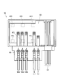
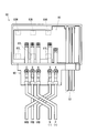
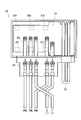
- FIG. 4 is a top view of the inverter unit 50 of the motor control device 30, and
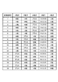
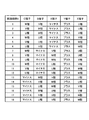
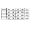
- FIG. 5 is a table showing a representative example of the connection state of each power line to the terminal portion of the inverter unit 50. It is.
- the motor 20 is a three-phase brushless motor, and includes a rotor (not shown) as a rotor and a stator 21 as a stator (see FIG. 3).
- the rotor is provided with a permanent magnet
- the stator 21 is provided with U-phase, V-phase, and W-phase coils 22U, 22V, and 22W.
- the power supply unit 40 of the motor control device 30 includes the power supply section 60, the precharge circuit section 70, and the voltage detection section 41 as described above as shown in FIG.
- the power supply unit 60 includes a battery 12 and a power supply switch 61.
- the battery 12 is a direct current power source, and the positive output terminal is set to the high voltage side, the negative output terminal is set to the low voltage side, and a direct current voltage is output between the positive output terminal and the negative output terminal.
- the power supply switch 61 is composed of a switching element and is disposed on the high voltage side of the battery 12. DC power is supplied to the inverter circuit unit 80 by turning on the switching element of the power supply switch 61 according to a command from the control unit 31.
- the precharge circuit unit 70 is installed in parallel with the power supply switch 61 and includes a switching element 71 and a resistor 72. Before the control unit 31 controls the power supply switch 61 to supply power to the inverter circuit unit 80, the control unit 31 conducts the switching element 71 of the precharge circuit unit 70 to charge the capacitor 51. Then, the control unit 31 turns on the power supply switch 61 to supply power to the inverter circuit unit 80 when the voltage of the capacitor 51 described later becomes equal to the voltage of the battery 12. Thereby, damage to the power supply switch 61 due to rapid charging can be prevented.
- the voltage detector 41 is installed between the high voltage side and the low voltage side of the battery 12.
- the voltage detection unit 41 detects the voltage of the capacitor 51 and sends the voltage information to the control unit 31 in order to drive the inverter circuit unit 80 appropriately.
- the inverter unit 50 of the motor control device 30 includes an inverter circuit unit 80 and a capacitor 51 as shown in FIG. Capacitor 51 plays a role of smoothing fluctuations of DC power output from power supply unit 60.
- the inverter circuit unit 80 includes a U-phase switching circuit 81, a V-phase switching circuit 82, and a W-phase switching circuit 83.
- Each switching circuit includes a pair of switching elements connected in series, and is connected in series between a high voltage side and a low voltage side of the battery 12 via a capacitor 51.
- the U-phase switching circuit 81 includes an upper arm side (high voltage side) switching element 81H and a lower arm side (low voltage side) switching element 81L.
- the V-phase switching circuit 82 includes an upper arm side (high voltage side) switching element 82H and a lower arm side (low voltage side) switching element 82L.
- the W-phase switching circuit 83 includes an upper arm side (high voltage side) switching element 83H and a lower arm side (low voltage side) switching element 83L.
- Each switching element includes a parasitic diode 84 whose forward direction is the reverse of the direction in which the current input to the motor 20 or the current output from the motor 20 flows.
- each switching element is controlled by the control unit 31, and the inverter circuit unit 80 converts the DC power into AC power by repeatedly conducting and interrupting the current of each switching element.
- the inverter circuit unit 80 converts the DC power into AC power by repeatedly conducting and interrupting the current of each switching element.
- a current flows through each of the U-phase, V-phase, and W-phase coils 22 U, 22 V, and 22 W of the motor 20.
- the control unit 31 changes the voltage level of the U-phase, V-phase, and W-phase voltage levels over time.
- the motor 20 or the motor control device 30 is provided with means for detecting a position related to the rotation direction of the rotor of the motor 20, and based on the position and a desired output torque of the motor 20, the control unit 31 A switching element that conducts current is selected.
- the motor 20, the power supply unit 40, and the inverter unit 50 are configured independently of each other, and are connected to each other by a power line for power and a signal line for control.
- the inverter unit 50 includes a power line terminal portion 90 and a signal line 52 as shown in FIG.
- the terminal unit 90 includes a total of five terminals, an X terminal, a Y terminal, an A terminal, a B terminal, and a C terminal.
- Positive and negative, that is, plus (P) and minus (N) input power lines for inputting power from the power supply unit 60 are individually connected to the X terminal and the Y terminal.
- U-phase, V-phase, and W-phase output power lines for outputting power to the motor 20 are individually connected to the A terminal, the B terminal, and the C terminal.
- the A terminal is wired so as to be connected between the upper arm side switching element 81 ⁇ / b> H and the lower arm side switching element 81 ⁇ / b> L connected in series in the U phase in the inverter circuit unit 80.
- a U-phase output power line is connected.
- the B terminal is wired so as to be connected between the V-phase series-connected upper arm side switching element 82H and lower arm side switching element 82L in the inverter circuit unit 80, and the V phase output power line of the motor 20 is connected. Is done.
- the C terminal is wired so as to be connected between the upper arm side switching element 83H and the lower arm side switching element 83L connected in series in the W phase in the inverter circuit unit 80, and the W phase output power line of the motor 20 is connected. Is done.
- FIGS. 3 and 4 depict a normal connection state between the input power line and the output power line in the terminal unit 90.
- tip of each power line are connected by screwing.
- the five round terminals at the tip of each power line have the same shape, and the terminals of the terminal portion 90 are also relatively close to each other, so there is a possibility that the connection is wrong.
- a connection state of each power line to the terminal unit 90 a typical example as shown in FIG. Examples 1 to 6 shown in FIG.
- the control unit 31 can determine an abnormality in the connection state of the terminal unit 90 due to an incorrect connection by a method described later.
- the control unit 31 uses the signal line 52 as a connection state output unit that outputs the abnormality information, and displays an error code or the like of the abnormality information on the display unit 9 that is a notification unit for the user.
- the abnormality information of the connection state at the terminal unit 90 of the inverter circuit unit 80 is output, the abnormality information is notified to the user, or other components are controlled based on the abnormality information. It is possible.
- the abnormality of the connection state in the terminal part 90 of the inverter circuit part 80 is alert
- FIGS. 6 to 23 Details of erroneous connection examples 1 to 6 of each power line to the terminal unit 90 will be described with reference to FIGS. 6 to 23 in addition to FIG. Note that in FIGS. 6 to 23, there are some cases where drawing of symbols that are not used in the following description is omitted.
- FIG. 6 is a top view of the inverter unit 50 similar to that of FIG. 4 showing the connection state of the erroneous connection example 1
- FIG. 7 is a schematic diagram showing the periphery of the motor control device 30 similar to FIG.
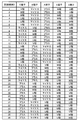
- FIG. 8 is a table showing all the connection states of the erroneous connection example 1.
- the negative (N) input power line to be connected to the Y terminal of the terminal unit 90 is connected to the C terminal to which the W-phase output power line is connected, and C The W-phase output power line to be connected to the terminal is connected to the Y terminal to which the negative (N) input power line is connected.
- the control unit 31 detects the voltage of the capacitor 51 using the voltage detection unit 41 in a state where the power is OFF (the power supply switch 61 and the switching element 71 are both OFF). If the connection is normal, the voltage of the capacitor 51 is detected. In the case of the erroneous connection example 1, since the current flows through the parasitic diode 84, the voltage of the capacitor 51 cannot be detected, that is, 0V is detected.
- connection states shown in FIGS. 5, 6, and 7 are examples of erroneous connection example 1. Similarly, there are many other connection states that are determined as erroneous connection example 1, as shown in FIG. To do.
- FIG. 9 is a top view of the inverter unit 50 similar to FIG. 4 and shows the connection state of the erroneous connection example 2
- FIG. 10 is a schematic diagram showing the periphery of the motor control device 30 similar to FIG.
- FIG. 11 is a table showing all the connection states of the erroneous connection example 2.
- the positive (P) input power line to be connected to the X terminal of the terminal unit 90 is connected to the A terminal to which the U-phase output power line is connected, and A The U-phase output power line to be connected to the terminal is connected to the X terminal to which the plus (P) input power line is connected.
- connection states shown in FIGS. 5, 9, and 10 are examples of erroneous connection example 2. Similarly, there are many other connection states that are determined as erroneous connection example 2, as shown in FIG. To do.
- the control unit 31 sets the terminal of the terminal unit 90 corresponding to the output power line based on the fact that the voltage of the capacitor 51 detected by the voltage detection unit 41 is 0V. It is determined that any one of the input power lines is connected and the connection state is abnormal. As a result, before driving the motor 20, the input power line from the power supply unit 60 is connected to the output terminal of the inverter circuit unit 80 without conducting current to the switching elements of the inverter circuit unit 80 as in normal operation. It is possible to grasp the abnormalities that have been made.
- FIG. 12 is a top view of the inverter unit 50 similar to FIG. 4 and shows the connection state of the erroneous connection example 3
- FIG. 13 is a schematic diagram showing the periphery of the motor control device 30 similar to FIG.
- FIG. 14 is a table showing all the connection states of the erroneous connection example 3, and shows a connection state of the erroneous connection example 3 in the configuration diagram.
- the negative (N) input power line to be connected to the Y terminal of the terminal unit 90 is connected to the C terminal to which the W-phase output power line is connected, and C
- the W-phase output power line to be connected to the terminal is connected to the Y terminal to which the negative (N) input power line is connected
- the plus (P) input power line to be connected to the X terminal is connected to the U-phase output power line.
- the U-phase output power line connected to the A terminal to be connected to the A terminal is connected to the X terminal to which the plus (P) input power line is connected.
- a current flows in the direction of the arrow indicated by a two-dot chain line F in FIG.
- the current is the parasitic diode 84 of the U-phase upper arm side switching element 81H of the inverter circuit unit 80, the U-phase coil 22U of the motor 20, the W-phase coil 22W, and the W-phase lower arm side of the inverter circuit unit 80. Since the battery returns to the battery 12 via the parasitic diode 84 of the switching element 83L, no electric charge is accumulated in the capacitor 51. Therefore, when the voltage detection unit 41 is used, the control unit 31 detects a voltage substantially equal to twice the voltage of the parasitic diode 84.
- connection states shown in FIGS. 5, 12, and 13 are examples of erroneous connection example 3. Similarly, there are many other connection states that are determined as erroneous connection example 3, as shown in FIG. To do.
- the control unit 31 responds to the output power line in the terminal unit 90 based on the fact that the voltage of the capacitor 51 detected by the voltage detection unit 41 is substantially equal to twice the voltage of the parasitic diode 84. It is determined that both the positive and negative input power lines are connected to the terminal to be connected and the connection state is abnormal. As a result, before driving the motor 20, the input power line from the power supply unit 60 is connected to the output terminal of the inverter circuit unit 80 without positive or negative current without conducting current to the switching elements of the inverter circuit unit 80 as in normal operation. Both can grasp the abnormality connected by mistake.
- FIG. 15 is a top view of the inverter unit 50 similar to FIG. 4 and shows the connection state of the erroneous connection example 4
- FIG. 16 is a schematic diagram showing the periphery of the motor control device 30 similar to FIG.
- FIG. 17 is a table showing all the connection states of the erroneous connection example 4, and shows the connection state of the erroneous connection example 4 in the configuration diagram.
- the positive (P) input power line to be connected to the X terminal of the terminal unit 90 is connected to the Y terminal to which the negative (N) input power line is connected
- the negative (N) input power line to be connected to the Y terminal is connected to the C terminal to which the W-phase output power line is connected
- the W-phase output power line to be connected to the C terminal is the positive (P) input power line. Is connected to the X terminal to be connected.
- connection states shown in FIGS. 5, 15, and 16 are examples of erroneous connection example 4. Similarly, there are many other connection states that are determined as erroneous connection example 4, as shown in FIG. To do.
- FIG. 18 is a top view of the inverter unit 50 similar to FIG. 4 and shows the connection state of the erroneous connection example 5
- FIG. 19 is a schematic diagram showing the periphery of the motor control device 30 similar to FIG.
- FIG. 20 is a table showing all the connection states of the erroneous connection example 5.
- the negative (N) input power line to be connected to the Y terminal of the terminal unit 90 is connected to the X terminal to which the positive (P) input power line is connected
- the positive (P) input power line to be connected to the X terminal is connected to the A terminal to which the U-phase output power line is connected
- the U-phase output power line to be connected to the A terminal is the negative (N) input power line. Is connected to the Y terminal to be connected.
- connection states shown in FIGS. 5, 18, and 19 are examples of erroneous connection example 5. Similarly, there are many other connection states that are determined as erroneous connection example 5, as shown in FIG. To do.
- the control unit 31 corresponds to the output power line in the terminal unit 90 based on the fact that the voltage of the capacitor 51 detected by the voltage detection unit 41 is the voltage of the parasitic diode 84. It is determined that one of the input power lines is connected to the terminal, and the other input power line is connected to a terminal corresponding to the input power line with a different sign, and the connection state is abnormal. As a result, before driving the motor 20, one of the positive and negative inputs from the power supply unit 60 is input to the output terminal of the inverter circuit unit 80 without conducting current to the switching element of the inverter circuit unit 80 as in normal operation. It is possible to grasp an abnormality in which the power line is connected and the other input power line is connected to the input terminal with a wrong polarity.
- FIG. 21 is a top view of the inverter unit 50 similar to FIG. 4 and shows the connection state of the erroneous connection example 6, and
- FIG. 22 is a schematic view showing the periphery of the motor control device 30 similar to FIG.
- FIG. 23 is a table showing all the connection states of the erroneous connection example 6.
- the positive (P) input power line to be connected to the X terminal of the terminal unit 90 is connected to the Y terminal to which the negative (N) input power line is connected
- the negative (N) input power line to be connected to the Y terminal is connected to the X terminal to which the positive (P) input power line is connected.
- the input power line is connected to the terminal unit 90 with the polarity reversed.
- connection states shown in FIGS. 5, 21, and 22 are examples of erroneous connection example 6.
- connection states determined as erroneous connection example 6 include the U phase and V phase as shown in FIG. , And the output power line of the W phase is replaced by a total of six types.
- the control unit 31 responds to the input power line in the terminal unit 90 based on the fact that the voltage of the capacitor 51 detected by the voltage detection unit 41 is substantially equal to twice the voltage of the parasitic diode 84. It is determined that the input power line is connected to the terminal to be reversed and the connection state is abnormal. As a result, before driving the motor 20, the input power line from the power supply unit 60 is connected to the input terminal of the inverter circuit unit 80 without positive or negative current without conducting current to the switching elements of the inverter circuit unit 80 as in normal operation. By reversing, you can grasp the abnormality connected by mistake.
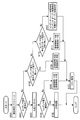
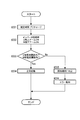
- FIG. 24 is a flowchart showing an operation related to detection of a connection state with respect to the terminal unit 90 of the inverter unit 50 according to the first embodiment of the present invention.
- the control unit 31 of the motor control device 30 executes precharge for the capacitor 51 using the precharge circuit unit 70 for a specified time (step # in FIG. 24). 101).
- This specified time is as short as possible so that the precharge can be sufficiently completed, and is determined by the specification of the capacitor 51, and can be set to, for example, 2 seconds.
- the control unit 31 checks the voltage of the capacitor 51 detected by the voltage detection unit 41 and determines whether or not the voltage is within a preset threshold value (step # 102).
- This “within threshold value” means a voltage range set for determining that the voltage of the capacitor 51 is substantially the same as the voltage of the battery 12 of the power supply unit 60, and can be changed as appropriate.
- step # 102 when the voltage of the capacitor 51 is within the threshold (Yes in step # 102), the control unit 31 turns off the switching element 71 of the precharge circuit unit 70 (step # 103). Again, the control unit 31 checks the voltage of the capacitor 51 detected by the voltage detection unit 41, and determines whether or not the voltage is within a preset threshold (step # 104).
- step # 104 If the voltage of the capacitor 51 is within the threshold value in step # 104 (Yes in step # 104), the control unit 31 turns on the power supply switch 61 of the power supply unit 60 to normally start the motor control device 30 (step # 105). ). And the operation
- control unit 31 connects the input power line and the output power line in the terminal unit 90 based on the fact that the voltage of the capacitor 51 detected by the voltage detection unit 41 is substantially the same as the voltage of the battery 12 of the power supply unit 60. It is determined that the state is normal. As a result, before the motor 20 is driven, the power supply unit 60 and the motor 20 are normally connected to the inverter circuit unit 80 without conducting current to the switching elements of the inverter circuit unit 80 as in normal operation. I can grasp that.
- step # 104 determines that the connection state between the input power line and the output power line in the terminal unit 90 is the erroneous connection example 1 described above or A determination is made that one of the abnormal connection examples 2 is abnormal (step # 106). Subsequently, the control unit 31 notifies the user of the error by displaying an error code on the display unit 9 (step # 107). And the control part 31 complete
- step # 108 the control unit 31 subsequently determines whether the voltage of the capacitor 51 is equal to the voltage of the parasitic diode 51 of the switching element of the inverter circuit unit 80. It is determined whether or not (step # 108).
- step # 108 when the voltage of the capacitor 51 is equal to the voltage of the parasitic diode 51 (Yes in step # 108), the control unit 31 is an erroneous connection example in which the connection state between the input power line and the output power line in the terminal unit 90 is described above. 4 or erroneous connection example 5 is determined (step # 109). Subsequently, the control unit 31 notifies the user of the error by displaying an error code on the display unit 9 (step # 107). And the control part 31 complete
- step # 110 the control unit 31 subsequently determines whether the voltage of the capacitor 51 is equal to twice the voltage of the parasitic diode 51. It is determined whether or not (step # 110).
- Step # 110 When the voltage of the capacitor 51 is equal to twice the voltage of the parasitic diode 51 in Step # 110 (Yes in Step # 110), the control unit 31 has previously described the connection state between the input power line and the output power line in the terminal unit 90. It is determined that there is an abnormality in erroneous connection example 3 or erroneous connection example 6 (step # 111). Subsequently, the control unit 31 notifies the user of the error by displaying an error code on the display unit 9 (step # 107). And the control part 31 complete
- step # 110 if the voltage of the capacitor 51 is not equal to twice the voltage of the parasitic diode 51 in step # 110 (No in step # 110), the control unit 31 has caused a short or open failure of the capacitor 51 or pre- It is determined that the switching element 71 of the charge circuit unit 70 has an open failure (step # 112). Subsequently, the control unit 31 notifies the user of the error by displaying an error code on the display unit 9 (step # 107). And the control part 31 complete
- the motor control device 30 determines the connection state between the input power line and the output power line in the terminal unit 90 based on the voltage of the capacitor 51 before the output of DC power from the power supply unit 60 to the inverter circuit unit 80. To do. Therefore, it is possible to grasp the erroneous connection of the power supply unit 60 and the motor 20 to the inverter circuit unit 80 without conducting current to the switching elements of the inverter circuit unit 80 as in the normal operation. In this way, it is possible to provide the motor control device 30 that can prevent the switching element of the inverter circuit unit 80 from being damaged due to erroneous connection of the power supply unit 60 or the motor 20 to the inverter circuit unit 80. Moreover, by mounting such a motor control device 30, it is possible to provide the electric vehicle 1 with improved reliability.
- FIG. 25 is a schematic configuration diagram showing the periphery of the motor control device
- FIG. 26 is a top view of the inverter unit of the motor control device, showing the connection state of misconnection example 7, and
- FIG. 27 is a motor control device similar to FIG.
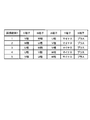
- FIG. 28 is a table showing all connection states of the misconnection example 7
- FIG. 29 is an inverter according to the second embodiment of the present invention. It is a flowchart which shows the operation
- the motor control device 30 includes a control unit 31, a power input unit 100, an inverter unit 50, and current detection units 32 and 33 shown in FIG.
- the power input unit 100 includes a voltage detection unit 101, a power supply switch 102 and a precharge circuit unit 70
- the inverter unit 50 includes an inverter circuit unit 80.
- the battery 12 is provided in the electric vehicle 1 as a separate body from the motor control device 30.
- the current detectors 32 and 33 are respectively installed corresponding to the U-phase power line and the W-phase power line extending from the inverter unit 50 toward the motor 20.
- the current detection units 32 and 33 detect the current flowing in the U phase and the current flowing in the W phase of the motor 20 and send the current information to the control unit 31.
- the motor 20, the power input unit 100, and the inverter unit 50 are each configured independently, and are connected to each other by a power line for power and a signal line for control. Therefore, the inverter unit 50 includes a power line terminal 90 and a signal line 52 (see FIG. 4). And based on such a structure, FIG. 25 is the input power line and output power line in the terminal part 90 (refer FIG. 4) provided with a total of five terminals, X terminal, Y terminal, A terminal, B terminal, and C terminal. Drawing the normal connection status.
- the five round terminals at the tip of each power line have the same shape, and the terminals of the terminal portion 90 are also relatively close to each other, as in the erroneous connection example 7 shown in FIGS. Connection may be wrong.
- the V-phase output power line to be connected to the B terminal of the terminal unit 90 is connected to the C terminal to which the W-phase output power line is connected, and the W-phase output power line to be connected to the C terminal is
- the V-phase output power line is connected to the B terminal to be connected. That is, the two input power lines are normally connected to the terminal unit 90, and the V-phase output power line and the W-phase output power line are connected to the terminal unit 90 in a reversed manner.
- the precharge ends normally because the input power line to the inverter unit 50 is in a normal connection state. Further, even after the precharge is completed, even if the voltage of the capacitor 51 is detected using the voltage detection unit 41 in a state where the control unit 31 is turned off (both the power supply switch 102 and the switching element 71 are turned off), the input power line to the inverter unit 50 Is a normal connection state, the proper voltage of the capacitor 51 is detected.
- connection state of the output power line of the inverter unit 50 is abnormal, even if power is turned on thereafter (both the power supply switch 102 and the switching element 71 are turned on) and power is supplied to the motor 20 via the inverter unit 50.
- the motor 20 does not drive normally. There is a possibility that the motor 20 becomes locked due to the inability to drive normally, and the amount of heat generated by the motor 20 becomes excessive. And there exists a possibility that the switching element of the inverter circuit part 80 may be damaged by the influence of the heat which the motor 20 generate
- the control unit 31 switches the upper arm side (high voltage side) switching element of any one of the three phases with the power OFF (the power supply switch 102 and the switching element 71 are both OFF).
- the other phase lower arm side (low voltage side) switching element for example, the U phase upper arm side switching element 81H and the W phase lower arm side switching element 83L are electrically connected to charge the capacitor 51 to the motor 20. Lead.
- the control unit 31 detects currents flowing in the U phase and the W phase of the motor 20 using the current detection units 32 and 33. In the normal connection state, a current within a predetermined threshold is detected, but in the case of erroneous connection example 7, a current that is out of the predetermined threshold is detected.
- the current detectors 32 and 33 are installed corresponding to the U phase and W phase of the motor 20 to detect the current flowing in the U phase and W phase of the motor 20.
- the combination of the two phases is an example, and the present invention is not limited to this.
- a current detection unit may be installed corresponding to the U phase and the V phase to detect the current flowing in the U phase and the V phase of the motor 20.
- the current detectors 32 and 33 are normally provided in the inverter unit 50 for the control of the motor 20 and the number of components increases because they are provided on the motor 20 side as in this embodiment. Not to do.
- the current threshold for determining the erroneous connection example 7 is an arbitrary value set in advance for the current flowing in the U phase and the W phase of the motor 20, and corresponds to the type, specification, performance, etc. of the motor 20. It can be set appropriately.
- connection states shown in FIGS. 26 and 27 are an example of erroneous connection example 7, and there are many other connection states that are similarly determined as erroneous connection example 7, as shown in FIG.
- control unit 31 of the motor control device 30 executes precharge for the capacitor 51 using the precharge circuit unit 70 for a specified time (step # in FIG. 29). 201).
- connection examples 1 to 6 and the like by checking the voltage of the capacitor 51 after precharging has been described with reference to FIG. 24 in the first embodiment, and thus description thereof is omitted here.
- control unit 31 conducts (ON) the U-phase upper arm side switching element 81H and the W-phase lower arm side switching element 83L in a state where the power is OFF (the power supply switch 102 and the switching element 71 are both OFF).
- the charge charged in the capacitor 51 is led to the motor 20 (step # 202).
- control part 31 checks the electric current which flows into the U phase and W phase of the motor 20 which the electric current detection parts 32 and 33 detected, and determines whether the electric current is in the preset threshold value (step # 203). ).
- step # 203 When the current flowing in the U phase and W phase of the motor 20 is within the threshold value in step # 203 (Yes in step # 203), the control unit 31 turns on the power supply switch 102 of the power input unit 100 to turn on the motor control device 30. Is normally activated (step # 204). And the operation
- step # 203 when the current flowing in the U phase and W phase of the motor 20 is out of the threshold value in step # 203 (No in step # 203), the control unit 31 indicates that the connection state of the output power line in the terminal unit 90 is an incorrect connection example. 7 is determined to be abnormal (step # 205). Subsequently, the control unit 31 notifies the user of the error by displaying an error code on the display unit 9 (see FIG. 1) (step # 206). And the control part 31 complete
- the current flowing through the U phase and the W phase of the motor 20 detected by the current detection units 32 and 33 before the control unit 31 supplies the DC power to the inverter circuit unit 80 in the case of erroneous connection example 7. It is determined that the connection state is abnormal because a different output power line is connected to a terminal corresponding to the output power line in the terminal unit 90 based on being out of the predetermined threshold. As a result, before driving the motor 20, the current is not conducted to the switching element of the inverter circuit unit 80 as in the normal operation, that is, by using the electric charge charged in the capacitor 51, the power is turned off (power supply switch).
- the electric vehicle 1 that is a moving body on which the motor control device 30 is mounted is described by taking the motorcycle shown in FIG. 1 as an example, but the electric vehicle to be mounted is limited to the motorcycle. However, it may be an auto tricycle or an auto four-wheel vehicle.
- the moving object to be mounted with the motor control device 30 of the present invention may be a vehicle such as a motor boat or a water play equipment, or a moving object that uses a motor as a driving source and moves unattended without a person on board. I do not care.
- condenser used in order to determine the connection state of the power line characterized by this invention are combined,
- the circuit configuration is not limited to this, and each capacitor may be provided separately. By also using a capacitor, an increase in circuit configuration can be suppressed.
- the present invention can be used in a motor control device including an inverter circuit.
Landscapes
- Engineering & Computer Science (AREA)
- Life Sciences & Earth Sciences (AREA)
- Sustainable Development (AREA)
- Sustainable Energy (AREA)
- Power Engineering (AREA)
- Transportation (AREA)
- Mechanical Engineering (AREA)
- Inverter Devices (AREA)
Abstract
モータ制御装置30は、入力された直流電力の変動分を平滑するコンデンサ51と、コンデンサ51の電圧を検出する電圧検出部41と、モータ20に電力を供給するインバータ回路部80と、インバータ回路部80に対する直流電力の供給前にコンデンサ51に充電を行うプリチャージ回路部70と、インバータ回路部80に直流電力を入力するための入力電力線とモータ20へ電力を出力するための出力電力線とが各々個別に接続される端子部90と、プリチャージ回路部70を制御してコンデンサ51に充電させ、電圧検出部41が検出したコンデンサ51の電圧に基づき端子部90における入力電力線と出力電力線との接続状態を判定する制御部31と、を備える。
Description
本発明は、インバータ回路を備えたモータ制御装置に関する。また、このモータ制御装置を搭載した電動車両を含む移動体に関する。
従来、電動車両などに適用されるモータの制御装置にはインバータ回路が利用されることが多い。インバータ回路は電源部が出力する直流電力をモータの駆動に必要な交流電力に変換する機能を備えている。インバータ回路はFET(Field Effect Transistor:電界効果トランジスタ)などで構成されるスイッチング素子を備えており、このスイッチング素子を制御して電流の導通、遮断を繰り返すことにより直流電力を交流電力に変換する。
インバータ回路は、例えば3相式のモータを制御する場合、3相(U相、V相、W相)の上アーム側(高電圧側)及び下アーム側(低電圧側)各々に対応して計6個のスイッチング素子が備えられているものがある。インバータ回路はこれらのスイッチング素子を制御して3相の電流の方向を切り替え、モータに所望の駆動力を与える。
このようなインバータ回路には電源部との間で配線される入力電力線と、モータとの間で配線される出力電力線とが接続される。そして、これらの配線を誤って接続した場合、接続状態に因っては電源部がショートする非常に危険な形になったり、インバータ回路のスイッチング素子が破損したりする虞がある。そこで、インバータ回路に対する電源部の誤接続の防止が検討され、その一例を特許文献1に見ることができる。
特許文献1に記載された電力変換装置はインバータ回路の上下アームのスイッチング素子とシャント抵抗とが直列に接続された直列接続回路部が複数個並列に接続されたブリッジ回路を構成している。そして、下アーム側全てを同時に導通させたときのシャント抵抗を流れる電流が0か否かで閾値判定して誤接続を検出する方法が開示されている。
しかしながら、特許文献1に記載された電力変換装置は負荷装置(例えばモータ)を接続すべき出力端子に電源装置が接続された状態において通常運転時と同様にインバータ回路のスイッチング素子に電流を導通させて誤接続を検出している。これにより、電源装置からの入力用の正負電力線が電力変換装置の入力端子、出力端子各々に接続された場合にスイッチング素子が破損する虞がある。
また、これに関連して、特許文献1に記載された電力変換装置では出力端子に電源装置が接続された場合について誤接続を検出する方法が開示されている。しかしながら、電源装置からの入力用の正負電力線が電力変換装置の入力端子、出力端子各々に接続された場合の誤接続の検出について考慮されていない。
本発明は上記の点に鑑みなされたものであり、モータを駆動させる前に、通常運転時と同様にインバータ回路のスイッチング素子に電流を導通させることなくインバータ回路に対する電源部やモータの誤接続を把握することができ、その誤接続に起因するインバータ回路のスイッチング素子の破損を防止することが可能なモータ制御装置を提供することを目的とする。また、このようなモータ制御装置を搭載することにより、信頼性が高められた電動車両を含む移動体を提供することを目的とする。
上記の課題を解決するため、本発明のモータ制御装置は、入力された直流電力の変動分を平滑するコンデンサと、前記コンデンサの電圧を検出する電圧検出部と、直流電力を交流電力に変換してモータに電力を供給するインバータ回路部と、前記インバータ回路部に対する前記直流電力の供給前に前記コンデンサに充電を行うプリチャージ回路部と、前記インバータ回路部に前記直流電力を入力するための入力電力線とモータへ電力を出力するための出力電力線とが各々個別に接続される複数の端子を有する端子部と、前記プリチャージ回路部を制御して前記コンデンサに充電させ、前記電圧検出部が検出した前記コンデンサの電圧に基づき前記端子部における前記入力電力線と前記出力電力線との接続状態を判定する制御部と、を備えることとした。
また本発明では、上記モータ制御装置を電動車両を含む移動体に搭載することとした。
本発明の構成によれば、インバータ回路に対する電源部、或いはモータの誤接続を把握することができる。
以下、本発明の実施形態を図1~図29に基づき説明する。
最初に、本発明の第1の実施形態に係るモータ制御装置を搭載した移動体である電動車両について、図1及び図2を用いてその構造を説明する。図1はモータ制御装置を搭載した電動車両の一例を示す側面図、図2は電動車両の構成を示すブロック図である。
電動車両1は、図1に示すように前輪2及び後輪3を備えた電動式の二輪車であり、具体的には電動式の自動二輪車である。電動車両1はメインフレーム4及びスイングアーム5が主たる骨組みとして構成されている。
メインフレーム4は前端部が上方に向かって屈曲しており、その前端部で前輪2及びハンドル6を操舵可能に支持している。ハンドル6には電動車両1の加減速時に用いるスロットル7と、制動時に用いるブレーキレバー8とが設けられている。左右のハンドル6の中央には表示部9が設けられている。表示部9は電源のON/OFFや走行速度など運転情報を表示するほか、電動車両1に障害が発生したときにその異常情報をエラーコード等によってユーザに報知する報知部として機能する。
メインフレーム4の後端側であって、電動車両1の前後方向の略中央部にはユーザが腰を掛けるシート10と、バッテリ収容部11とが備えられている。バッテリ収容部11はシート10の下方に設けられ、内部にバッテリ12を収容することができる。シート10はバッテリ収容部11の蓋の役目も果たし、バッテリ収容部11に対して開閉可能にして取り付けられている。メインフレーム4のシート10の後方であって、後輪3の上方の箇所には荷物台13が備えられている。
スイングアーム5はメインフレーム4後部の、シート10及びバッテリ収容部11の箇所の下方から後方に向かって延びている。後輪3はスイングアーム5の後端に支持されている。また、後輪3は駆動輪であり、スイングアーム5との間に後輪3を駆動させるモータ20を備えている。すなわち、スイングアーム5はモータ20及び後輪3の回転軸を水平にして支持している。また、スイングアーム5のモータ20の箇所の上部から上方の荷物台13に向かって、モータ20及び後輪3を吊り下げるサスペンションユニット14が設けられている。
また、電動車両1は車両全体の動作制御のため、図2に示すようにその内部にモータ制御装置30を備えている。モータ制御装置30は制御部31、電源ユニット40、及びインバータユニット50を備えている。そして、電源ユニット40が電源部60、プリチャージ回路部70、及び電圧検出部41を備え、インバータユニット50がインバータ回路部80を備えている。なお、制御部31は一般的なマイコンによって構成され、このマイコン内部に記憶、入力されたプログラム、データに基づいて電動車両1の走行に係る一連の動作を制御するプロセッサとして機能するものである。
電動車両1を走行させるとき、制御部31はユーザが操作するスロットル7から得られるスロットル7の開き具合に応じたモータ20に対する目標トルクを設定する。そして、制御部31は電源部60から供給される電力に対して、インバータ回路部80を制御してモータ20に送るべき電流や電圧などを調整し、モータ20を駆動させる。
続いて、モータ20及びモータ制御装置30の詳細な構成について、図1及び図2に加えて図3~図5を用いて説明する。図3はモータ制御装置30周辺を示す概略構成図、図4はモータ制御装置30のインバータユニット50の上面図、図5はインバータユニット50の端子部に対する各電力線の接続状態の代表例を示す表である。
モータ20は3相式のブラシレスモータであって、回転子であるロータ(図示せず)と、固定子であるステータ21とを備えている(図3参照)。ロータには永久磁石が設けられ、ステータ21にはU相、V相、及びW相のコイル22U、22V、及び22Wが設けられている。
モータ制御装置30の電源ユニット40は、図3に示すように前述のとおり電源部60、プリチャージ回路部70、及び電圧検出部41を備えている。
電源部60はバッテリ12と、電源供給スイッチ61とを備えている。バッテリ12は直流電源であって正出力端子を高電圧側と、負出力端子を低電圧側とし、正出力端子と負出力端子との間に直流電圧を出力する。電源供給スイッチ61はスイッチング素子で構成され、バッテリ12の高電圧側に配置されている。制御部31からの指令により電源供給スイッチ61のスイッチング素子を導通させることにより、インバータ回路部80に直流電力が供給される。
プリチャージ回路部70は電源供給スイッチ61と並列にして設置され、スイッチング素子71と、抵抗72とを備えている。制御部31は電源供給スイッチ61を制御してインバータ回路部80に電力を供給する前に、プリチャージ回路部70のスイッチング素子71を導通させてコンデンサ51を充電させる。そして、制御部31は後述するコンデンサ51の電圧がバッテリ12の電圧を同じになった時点で電源供給スイッチ61をONにしてインバータ回路部80に電力を供給する。これにより、急激な充電に起因する電源供給スイッチ61の破損を防止することができる。
電圧検出部41はバッテリ12の高電圧側と低電圧側との間に設置されている。電圧検出部41はインバータ回路部80を好適に駆動させるため、コンデンサ51の電圧を検出してその電圧情報を制御部31に送っている。
モータ制御装置30のインバータユニット50は、図3に示すようにインバータ回路部80と、コンデンサ51とを備えている。なお、コンデンサ51は電源部60が出力した直流電力の変動分を平滑する役割を果たす。
インバータ回路部80はU相用スイッチング回路81、V相用スイッチング回路82、及びW相用スイッチング回路83を備えている。各スイッチング回路は直列接続された一対のスイッチング素子を備え、コンデンサ51を介してバッテリ12の高電圧側と低電圧側との間に直列接続されている。
U相用スイッチング回路81は上アーム側(高電圧側)スイッチング素子81Hと、下アーム側(低電圧側)スイッチング素子81Lとで構成されている。V相用スイッチング回路82は上アーム側(高電圧側)スイッチング素子82Hと、下アーム側(低電圧側)スイッチング素子82Lとで構成されている。W相用スイッチング回路83は上アーム側(高電圧側)スイッチング素子83Hと、下アーム側(低電圧側)スイッチング素子83Lとで構成されている。なお、各スイッチング素子はモータ20に入力する電流またはモータ20から出力される電流が流れる方向の逆方向を順方向とする寄生ダイオード84を各々備えている。
そして、制御部31によって各スイッチング素子のスイッチング動作が制御され、インバータ回路部80は各スイッチング素子の電流の導通、遮断を繰り返すことにより直流電力を交流電力に変換する。この交流電力がモータ20に供給されることにより、モータ20のU相、V相、及びW相の各コイル22U、22V、及び22Wに電流が流れて駆動される。
インバータ回路部80が直流電力を交流電力に変換するにあたって、制御部31はU相、V相、及びW相の電圧レベルの高低関係を時間の経過とともに変化させる。なお、モータ20或いはモータ制御装置30にはモータ20のロータの回転方向に係る位置を検出する手段が設けられており、その位置と、所望するモータ20の出力トルクとに基づき、制御部31は電流を導通させるスイッチング素子を選択する。
このようなモータ20、電源ユニット40、及びインバータユニット50は各々独立して構成され、互いに動力用の電力線と、制御用の信号線とで接続されている。このため、インバータユニット50は、図4に示すように電力線用の端子部90と、信号線52とを備えている。
端子部90はX端子、Y端子、A端子、B端子、及びC端子の計5箇所の端子を備えている。X端子、Y端子には電源部60から電力を入力するための正負、すなわちプラス(P)とマイナス(N)の入力電力線が個別に接続される。A端子、B端子、及びC端子にはモータ20に電力を出力するためのU相、V相、及びW相の出力電力線が個別に接続される。
なお、図3に示すように、A端子はインバータ回路部80におけるU相の直列接続された上アーム側スイッチング素子81Hと下アーム側スイッチング素子81Lとの間に繋がるように配線され、モータ20のU相の出力電力線が接続される。また、B端子はインバータ回路部80におけるV相の直列接続された上アーム側スイッチング素子82Hと下アーム側スイッチング素子82Lとの間に繋がるように配線され、モータ20のV相の出力電力線が接続される。また、C端子はインバータ回路部80におけるW相の直列接続された上アーム側スイッチング素子83Hと下アーム側スイッチング素子83Lとの間に繋がるように配線され、モータ20のW相の出力電力線が接続される。
このような構成に基づき、図3及び図4は端子部90における入力電力線と出力電力線との正常な接続状態を描画している。なお、端子部90の各端子と各電力線の先端に取り付けられた丸端子とはネジ止めすることによって接続される。
ここで、各電力線先端の丸端子は5本とも同一の形状をなしており、端子部90の各端子も比較的近接しているので、接続を間違う可能性がある。端子部90に対する各電力線の接続状態としては図5に示したような代表的な例が挙げられる。誤接続は図5に示す例1~例6が考えられる。制御部31は誤接続による端子部90の接続状態の異常を後述する方法で判定することができる。
そして、制御部31はその異常情報を出力する接続状態出力部として信号線52を利用し、ユーザに対する報知部である表示部9に異常情報のエラーコード等を表示させる。このようにして、インバータ回路部80の端子部90における接続状態の異常情報が出力されるので、その異常情報をユーザに報知するようにしたり、異常情報に基づき他の構成要素を制御したりすることが可能である。そして、電動車両1の表示部9を介してユーザにインバータ回路部80の端子部90における接続状態の異常が報知されるので、ユーザは電動車両1の異常を容易に把握でき、修理等に迅速に対応することが可能である。
続いて、端子部90に対する各電力線の誤接続例1~例6の詳細について、図5に加えて図6~図23を用いて説明する。なお、図6~図23において、以下の説明で使用することがない符号の描画を一部省略している場合がある。
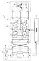
誤接続例1に関して、図6は図4と同様のインバータユニット50の上面図にして、誤接続例1の接続状態を示すもの、図7は図3と同様のモータ制御装置30周辺を示す概略構成図にして、誤接続例1の接続状態を示すもの、図8は誤接続例1のすべての接続状態を示す表である。
誤接続例1では、図6及び図7に示すように端子部90のY端子に接続すべきマイナス(N)の入力電力線がW相の出力電力線を接続すべきC端子に接続され、且つC端子に接続すべきW相の出力電力線がマイナス(N)の入力電力線を接続すべきY端子に接続されている。
この場合、電源部60によるプリチャージを開始すると、図7に二点鎖線Fで示した矢印の方向に電流が流れる。電流はインバータ回路部80のW相用下アーム側スイッチング素子83Lの寄生ダイオード84を経由して流れる。これにより、コンデンサ51が充電され、プリチャージは正常に終了する。しかしながらその後、電源をON(電源供給スイッチ61、スイッチング素子71ともにON)にしてインバータ回路部80に電力を供給すると、インバータ回路部80のスイッチング素子と電源部60との間でショートループが生じて回路が破損する。
このため、制御部31はプリチャージ終了後、電源OFF(電源供給スイッチ61、スイッチング素子71ともにOFF)の状態で電圧検出部41を用いてコンデンサ51の電圧を検出する。正常な接続状態であればコンデンサ51の電圧が検出されるが、誤接続例1の場合は電流が寄生ダイオード84を流れるのでコンデンサ51の電圧を検出できない、すなわち0Vが検出される。
なお、図5、図6及び図7に示した接続状態は誤接続例1の一例であり、同様に誤接続例1として判断される接続状態は、図8に示すように他にも多数存在する。
誤接続例2に関して、図9は図4と同様のインバータユニット50の上面図にして、誤接続例2の接続状態を示すもの、図10は図3と同様のモータ制御装置30周辺を示す概略構成図にして、誤接続例2の接続状態を示すもの、図11は誤接続例2のすべての接続状態を示す表である。
誤接続例2では、図9及び図10に示すように端子部90のX端子に接続すべきプラス(P)の入力電力線がU相の出力電力線を接続すべきA端子に接続され、且つA端子に接続すべきU相の出力電力線がプラス(P)の入力電力線を接続すべきX端子に接続されている。
この場合も誤接続例1と同様、電源部60によるプリチャージを開始すると、図10に二点鎖線Fで示した矢印の方向に電流が流れる。電流はインバータ回路部80のU相用上アーム側スイッチング素子81Hの寄生ダイオード84を経由して流れる。これにより、コンデンサ51が充電され、プリチャージは正常に終了する。制御部31はプリチャージ終了後、電源OFF(電源供給スイッチ61、スイッチング素子71ともにOFF)の状態で電圧検出部41を用いてコンデンサ51の電圧を検出すると、誤接続例1と同様に0Vを検出する。
なお、図5、図9及び図10に示した接続状態は誤接続例2の一例であり、同様に誤接続例2として判断される接続状態は、図11に示すように他にも多数存在する。
このようにして、誤接続例1及び誤接続例2のとき制御部31は、電圧検出部41が検出したコンデンサ51の電圧が0Vであることに基づき端子部90における出力電力線に対応する端子にいずれか一方の入力電力線が接続されて接続状態が異常であると判定する。その結果、モータ20を駆動させる前に、通常運転時と同様にインバータ回路部80のスイッチング素子に電流を導通させることなく、インバータ回路部80の出力用端子に電源部60からの入力電力線が接続されている異常を把握できる。
誤接続例3に関して、図12は図4と同様のインバータユニット50の上面図にして、誤接続例3の接続状態を示すもの、図13は図3と同様のモータ制御装置30周辺を示す概略構成図にして、誤接続例3の接続状態を示すもの、図14は誤接続例3のすべての接続状態を示す表である。
誤接続例3では、図12及び図13に示すように端子部90のY端子に接続すべきマイナス(N)の入力電力線がW相の出力電力線を接続すべきC端子に接続され、且つC端子に接続すべきW相の出力電力線がマイナス(N)の入力電力線を接続すべきY端子に接続され、さらにX端子に接続すべきプラス(P)の入力電力線がU相の出力電力線を接続すべきA端子に接続され、且つA端子に接続すべきU相の出力電力線がプラス(P)の入力電力線を接続すべきX端子に接続されている。
この場合、電源部60によるプリチャージを開始すると、図13に二点鎖線Fで示した矢印の方向に電流が流れる。電流はインバータ回路部80のU相用上アーム側スイッチング素子81Hの寄生ダイオード84と、モータ20のU相用コイル22Uと、W相用コイル22Wと、インバータ回路部80のW相用下アーム側スイッチング素子83Lの寄生ダイオード84とを経由してバッテリ12に戻るので、コンデンサ51には電荷が溜まらない。そこで電圧検出部41を用いると、制御部31は寄生ダイオード84の電圧の2倍に略等しい電圧を検出することになる。
なお、図5、図12及び図13に示した接続状態は誤接続例3の一例であり、同様に誤接続例3として判断される接続状態は、図14に示すように他にも多数存在する。
このようにして、誤接続例3のとき制御部31は、電圧検出部41が検出したコンデンサ51の電圧が寄生ダイオード84の電圧の2倍に略等しいことに基づき端子部90における出力電力線に対応する端子に正負両方の入力電力線が接続されて接続状態が異常であると判定する。その結果、モータ20を駆動させる前に、通常運転時と同様にインバータ回路部80のスイッチング素子に電流を導通させることなく、インバータ回路部80の出力用端子に電源部60からの入力電力線が正負両方とも間違えて接続されている異常を把握できる。
誤接続例4に関して、図15は図4と同様のインバータユニット50の上面図にして、誤接続例4の接続状態を示すもの、図16は図3と同様のモータ制御装置30周辺を示す概略構成図にして、誤接続例4の接続状態を示すもの、図17は誤接続例4のすべての接続状態を示す表である。
誤接続例4では、図15及び図16に示すように端子部90のX端子に接続すべきプラス(P)の入力電力線がマイナス(N)の入力電力線を接続すべきY端子に接続され、且つY端子に接続すべきマイナス(N)の入力電力線がW相の出力電力線を接続すべきC端子に接続され、且つC端子に接続すべきW相の出力電力線がプラス(P)の入力電力線を接続すべきX端子に接続されている。
この場合、電源部60によるプリチャージを開始すると、図16に二点鎖線Fで示した矢印の方向に電流が流れる。電流はインバータ回路部80のW相用下アーム側スイッチング素子83Lの寄生ダイオード84を経由してバッテリ12に戻るので、コンデンサ51に電荷が溜まらない。そこで電圧検出部41を用いると、制御部31は寄生ダイオード84の電圧を検出することになる。
なお、図5、図15及び図16に示した接続状態は誤接続例4の一例であり、同様に誤接続例4として判断される接続状態は、図17に示すように他にも多数存在する。
誤接続例5に関して、図18は図4と同様のインバータユニット50の上面図にして、誤接続例5の接続状態を示すもの、図19は図3と同様のモータ制御装置30周辺を示す概略構成図にして、誤接続例5の接続状態を示すもの、図20は誤接続例5のすべての接続状態を示す表である。
誤接続例5では、図18及び図19に示すように端子部90のY端子に接続すべきマイナス(N)の入力電力線がプラス(P)の入力電力線を接続すべきX端子に接続され、且つX端子に接続すべきプラス(P)の入力電力線がU相の出力電力線を接続すべきA端子に接続され、且つA端子に接続すべきU相の出力電力線がマイナス(N)の入力電力線を接続すべきY端子に接続されている。
この場合も誤接続例4と同様、電源部60によるプリチャージを開始すると、図19に二点鎖線Fで示した矢印の方向に電流が流れる。電流はインバータ回路部80のU相用上アーム側スイッチング素子81Hの寄生ダイオード84を経由してバッテリ12に戻るので、コンデンサ51に電荷が溜まらない。そこで電圧検出部41を用いると、制御部31は寄生ダイオード84の電圧を検出することになる。
なお、図5、図18及び図19に示した接続状態は誤接続例5の一例であり、同様に誤接続例5として判断される接続状態は、図20に示すように他にも多数存在する。
このようにして、誤接続例4及び例5のとき制御部31は、電圧検出部41が検出したコンデンサ51の電圧が寄生ダイオード84の電圧であることに基づき端子部90における出力電力線に対応する端子にいずれか一方の入力電力線が接続され、且つ他方の入力電力線が正負を違えて入力電力線に対応する端子に接続されて接続状態が異常であると判定する。その結果、モータ20を駆動させる前に、通常運転時と同様にインバータ回路部80のスイッチング素子に電流を導通させることなく、インバータ回路部80の出力用端子に電源部60からの正負一方の入力電力線が接続され、且つ他方の入力電力線が正負を間違えて入力用端子に接続されている異常を把握できる。
誤接続例6に関して、図21は図4と同様のインバータユニット50の上面図にして、誤接続例6の接続状態を示すもの、図22は図3と同様のモータ制御装置30周辺を示す概略構成図にして、誤接続例6の接続状態を示すもの、図23は誤接続例6のすべての接続状態を示す表である。
誤接続例6では、図21及び図22に示すように端子部90のX端子に接続すべきプラス(P)の入力電力線がマイナス(N)の入力電力線を接続すべきY端子に接続され、且つY端子に接続すべきマイナス(N)の入力電力線がプラス(P)の入力電力線を接続すべきX端子に接続されている。すなわち、入力電力線が正負を逆にして端子部90に接続されている。
この場合、電源部60によるプリチャージを開始すると、図22に二点鎖線Fで示した矢印の方向に電流が流れる。電流はインバータ回路部80の下アーム側及び上アーム側各々のスイッチング素子の寄生ダイオード84を経由してバッテリ12に戻るので、コンデンサ51に電荷が溜まらない。そこで電圧検出部41を用いると、制御部31は寄生ダイオード84の電圧の2倍に略等しい電圧を検出することになる。
なお、図5、図21及び図22に示した接続状態は誤接続例6の一例であり、同様に誤接続例6として判断される接続状態は、図23に示すようにU相、V相、及びW相の出力電力線を入れ替えることにより計6通り存在する。
このようにして、誤接続例6のとき制御部31は、電圧検出部41が検出したコンデンサ51の電圧が寄生ダイオード84の電圧の2倍に略等しいことに基づき端子部90における入力電力線に対応する端子に正負を逆にして入力電力線が接続されて接続状態が異常であると判定する。その結果、モータ20を駆動させる前に、通常運転時と同様にインバータ回路部80のスイッチング素子に電流を導通させることなく、インバータ回路部80の入力用端子に電源部60からの入力電力線が正負を逆にして間違えて接続されている異常を把握できる。
続いて、端子部90に対する各電力線の接続状態の検出に係る動作について、図24に示すフローに沿って説明する。図24は本発明の第1の実施形態に係るインバータユニット50の端子部90に対する接続状態の検出に係る動作を示すフローチャートである。
電動車両1に電源が投入されると(図24のスタート)、モータ制御装置30の制御部31はプリチャージ回路部70を用いたコンデンサ51に対するプリチャージを規定時間実行する(図24のステップ#101)。この規定時間はプリチャージを十分に完了できるできるだけ短い時間であってコンデンサ51の仕様などによって決定され、例えば2秒間といった時間を設定できる。その規定時間を経過すると、制御部31は電圧検出部41が検出したコンデンサ51の電圧をチェックし、その電圧が予め設定した閾値内であるか否かを判定する(ステップ#102)。この「閾値内」とはコンデンサ51の電圧が電源部60のバッテリ12の電圧と略同じであることを判定するために設定された電圧の範囲を意味し、適宜変更することができる。
ステップ#102においてコンデンサ51の電圧が閾値内である場合(ステップ#102のYes)、制御部31はプリチャージ回路部70のスイッチング素子71をOFFにする(ステップ#103)。そして再度、制御部31は電圧検出部41が検出したコンデンサ51の電圧をチェックし、その電圧が予め設定した閾値内であるか否かを判定する(ステップ#104)。
ステップ#104においてコンデンサ51の電圧が閾値内である場合(ステップ#104のYes)、制御部31は電源部60の電源供給スイッチ61をONにしてモータ制御装置30を正常起動させる(ステップ#105)。そして、端子部90に対する各電力線の接続状態の検出に係る動作フローを終了する(図24のエンド)。
このようにして、制御部31は、電圧検出部41が検出したコンデンサ51の電圧が電源部60のバッテリ12の電圧と略同じであることに基づき端子部90における入力電力線と出力電力線との接続状態が正常であると判定する。その結果、モータ20を駆動させる前に、通常運転時と同様にインバータ回路部80のスイッチング素子に電流を導通させることなく、インバータ回路部80に対して電源部60やモータ20が正常に接続されているのを把握できる。
一方、ステップ#104においてコンデンサ51の電圧が閾値内でない場合(ステップ#104のNo)、制御部31は端子部90における入力電力線と出力電力線との接続状態が先に説明した誤接続例1または誤接続例2の異常のいずれかであるという判定を下す(ステップ#106)。続いて、制御部31は表示部9にエラーコードを表示するなどしてユーザにエラーを報知する(ステップ#107)。そして、制御部31はモータ制御装置30を起動させることなく端子部90に対する各電力線の接続状態の検出に係る動作フローを終了する(図24のエンド)。
また、ステップ#102においてコンデンサ51の電圧が閾値内でない場合(ステップ#102のNo)、続いて制御部31はコンデンサ51の電圧がインバータ回路部80のスイッチング素子の寄生ダイオード51の電圧に等しいか否かを判定する(ステップ#108)。
ステップ#108においてコンデンサ51の電圧が寄生ダイオード51の電圧に等しい場合(ステップ#108のYes)、制御部31は端子部90における入力電力線と出力電力線との接続状態が先に説明した誤接続例4または誤接続例5の異常であるという判定を下す(ステップ#109)。続いて、制御部31は表示部9にエラーコードを表示するなどしてユーザにエラーを報知する(ステップ#107)。そして、制御部31はモータ制御装置30を起動させることなく端子部90に対する各電力線の接続状態の検出に係る動作フローを終了する(図24のエンド)。
一方、ステップ#108においてコンデンサ51の電圧が寄生ダイオード51の電圧に等しくない場合(ステップ#108のNo)、続いて制御部31はコンデンサ51の電圧が寄生ダイオード51の電圧の2倍に等しいか否かを判定する(ステップ#110)。
ステップ#110においてコンデンサ51の電圧が寄生ダイオード51の電圧の2倍に等しい場合(ステップ#110のYes)、制御部31は端子部90における入力電力線と出力電力線との接続状態が先に説明した誤接続例3または誤接続例6の異常であるという判定を下す(ステップ#111)。続いて、制御部31は表示部9にエラーコードを表示するなどしてユーザにエラーを報知する(ステップ#107)。そして、制御部31はモータ制御装置30を起動させることなく端子部90に対する各電力線の接続状態の検出に係る動作フローを終了する(図24のエンド)。
一方、ステップ#110においてコンデンサ51の電圧が寄生ダイオード51の電圧の2倍に等しくない場合(ステップ#110のNo)、制御部31はコンデンサ51がショートまたはオープンの故障を起こしている、或いはプリチャージ回路部70のスイッチング素子71がオープンの故障を起こしているという判定を下す(ステップ#112)。続いて、制御部31は表示部9にエラーコードを表示するなどしてユーザにエラーを報知する(ステップ#107)。そして、制御部31はモータ制御装置30を起動させることなく端子部90に対する各電力線の接続状態の検出に係る動作フローを終了する(図24のエンド)。
上記実施形態によれば、モータ制御装置30はインバータ回路部80に対する電源部60からの直流電力の出力前に、コンデンサ51の電圧に基づき端子部90における入力電力線と出力電力線との接続状態を判定する。したがって、通常運転時と同様にインバータ回路部80のスイッチング素子に電流を導通させることなくインバータ回路部80に対する電源部60やモータ20の誤接続を把握することができる。このようにして、インバータ回路部80に対する電源部60やモータ20の誤接続に起因するインバータ回路部80のスイッチング素子の破損を防止することが可能なモータ制御装置30を提供することができる。また、このようなモータ制御装置30を搭載することにより、信頼性が高められた電動車両1を提供することができる。
次に、本発明の第2の実施形態に係るモータ制御装置の詳細な構成について、図25~図29を用いて説明する。図25はモータ制御装置周辺を示す概略構成図、図26はモータ制御装置のインバータユニットの上面図にして、誤接続例7の接続状態を示すもの、図27は図25と同様のモータ制御装置周辺を示す概略構成図にして、誤接続例7の接続状態を示すもの、図28は誤接続例7のすべての接続状態を示す表、図29は本発明の第2の実施形態に係るインバータユニットの端子部に対する接続状態の検出に係る動作を示すフローチャートである。なお、この実施形態の基本的な構成は図1~図24を用いて説明した前記第1の実施形態と同じであるので、第1の実施形態と共通する構成要素には前と同じ符号を付し、図面の記載及びその説明を省略するものとする。
第2の実施形態に係るモータ制御装置30は、図25に示す制御部31、電源入力ユニット100、インバータユニット50及び電流検出部32、33を備えている。電源入力ユニット100は電圧検出部101、電源供給スイッチ102及びプリチャージ回路部70を備え、インバータユニット50はインバータ回路部80を備えている。なお、バッテリ12はモータ制御装置30に対して別体として電動車両1に設けられている。
電流検出部32、33はインバータユニット50からモータ20に向かって延びるU相用の電力線とW相用の電力線とに対応させて各々設置されている。電流検出部32、33はモータ20を好適に駆動させるため、モータ20のU相に流れる電流とW相に流れる電流とを検出してその電流情報を制御部31に送っている。
モータ20、電源入力ユニット100及びインバータユニット50は各々独立して構成され、互いに動力用の電力線と制御用の信号線とで接続されている。このため、インバータユニット50は電力線用の端子部90と信号線52とを備えている(図4参照)。そして、このような構成に基づき、図25はX端子、Y端子、A端子、B端子、及びC端子の計5箇所の端子を備える端子部90(図4参照)における入力電力線と出力電力線との正常な接続状態を描画している。
ここで、各電力線先端の丸端子は5本とも同一の形状をなしており、端子部90の各端子も比較的近接しているので、図26及び図27に示す誤接続例7のように接続を間違う可能性がある。誤接続例7では、端子部90のB端子に接続すべきV相の出力電力線がW相の出力電力線を接続すべきC端子に接続され、且つC端子に接続すべきW相の出力電力線がV相の出力電力線を接続すべきB端子に接続されている。すなわち、2本の入力電力線は端子部90に対して正常に接続され、V相の出力電力線とW相の出力電力線とが入れ違えて端子部90に接続されている。
この場合、電源入力ユニット100によるプリチャージを開始すると、インバータユニット50に対する入力電力線が正常な接続状態であるのでプリチャージは正常に終了する。さらにプリチャージ終了後、制御部31が電源OFF(電源供給スイッチ102、スイッチング素子71ともにOFF)の状態で電圧検出部41を用いてコンデンサ51の電圧を検出しても、インバータユニット50に対する入力電力線が正常な接続状態であるので適正なコンデンサ51の電圧が検出される。
しかしながら、インバータユニット50の出力電力線の接続状態が異常であるので、その後電源をON(電源供給スイッチ102、スイッチング素子71ともにON)にしてインバータユニット50を介してモータ20に電力を供給しても、モータ20は正常に駆動しない。モータ20が正常に駆動できないことに起因してロック状態となり、モータ20の発熱量が過大になる可能性がある。そして、モータ20で発生する熱の影響によりインバータ回路部80のスイッチング素子が破損する虞がある。
このため、制御部31はプリチャージ終了後、電源OFF(電源供給スイッチ102、スイッチング素子71ともにOFF)の状態で3相のうちいずれかの相の上アーム側(高電圧側)のスイッチング素子とその他の相の下アーム側(低電圧側)のスイッチング素子、例えばU相上アーム側スイッチング素子81HとW相下アーム側スイッチング素子83Lとを導通させてコンデンサ51に充電させた電荷をモータ20に導く。さらに、制御部31は電流検出部32、33を用いてモータ20のU相及びW相に流れる電流を検出する。正常な接続状態であれば所定の閾値内の電流が検出されるが、誤接続例7の場合は所定の閾値内から外れた電流が検出される。
なお、誤接続例7を判定するためにモータ20のU相とW相とに対応させて電流検出部32、33を設置してモータ20のU相及びW相に流れる電流を検出することにしたが、この2相の組み合わせは一例であってこれに限定されるわけではない。例えば、U相とV相とに対応させて電流検出部を設置してモータ20のU相及びV相に流れる電流を検出することにしても良い。また、電流検出部32、33はモータ20の制御などのために通常インバータユニット50に設けられるものであって、本実施形態のようにこれらをモータ20側に設けたからといって部品点数が増加するわけではない。
また、誤接続例7を判定するための電流の閾値はモータ20のU相及びW相に流れる電流について予め設定した任意の値であって、モータ20の種類や仕様、性能などに対応して適宜設定することができる。
また、図26及び図27に示した接続状態は誤接続例7の一例であり、同様に誤接続例7として判断される接続状態は、図28に示すように他にも多数存在する。
続いて、端子部90に対する出力電力線の接続状態の検出に係る動作について、図29に示すフローに沿って説明する。
電動車両1に電源が投入されると(図29のスタート)、モータ制御装置30の制御部31はプリチャージ回路部70を用いたコンデンサ51に対するプリチャージを規定時間実行する(図29のステップ#201)。
なお、プリチャージ後のコンデンサ51の電圧をチェックすることによる誤接続例1~6等の判定については前記第1の実施形態で図24を用いて説明したので、ここではその説明を省略する。
続いて、制御部31は電源OFF(電源供給スイッチ102、スイッチング素子71ともにOFF)の状態でU相上アーム側スイッチング素子81HとW相下アーム側スイッチング素子83Lとを導通(ON)させ、プリチャージでコンデンサ51に充電させた電荷をモータ20に導く(ステップ#202)。そして、制御部31は電流検出部32、33が検出したモータ20のU相及びW相に流れる電流をチェックし、その電流が予め設定した閾値内であるか否かを判定する(ステップ#203)。
ステップ#203においてモータ20のU相及びW相に流れる電流が閾値内である場合(ステップ#203のYes)、制御部31は電源入力ユニット100の電源供給スイッチ102をONにしてモータ制御装置30を正常起動させる(ステップ#204)。そして、端子部90に対する出力電力線の接続状態の検出に係る動作フローを終了する(図29のエンド)。
一方、ステップ#203においてモータ20のU相及びW相に流れる電流が閾値内から外れている場合(ステップ#203のNo)、制御部31は端子部90における出力電力線の接続状態が誤接続例7の異常であるという判定を下す(ステップ#205)。続いて、制御部31は表示部9(図1参照)にエラーコードを表示するなどしてユーザにエラーを報知する(ステップ#206)。そして、制御部31はモータ制御装置30を起動させることなく端子部90に対する出力電力線の接続状態の検出に係る動作フローを終了する(図29のエンド)。
上記実施形態によれば、誤接続例7のとき制御部31はインバータ回路部80に対する直流電力の供給前に、電流検出部32、33が検出したモータ20のU相及びW相に流れる電流が所定の閾値内から外れていることに基づき端子部90における出力電力線に対応する端子に異なる出力電力線が接続されて接続状態が異常であると判定する。その結果、モータ20を駆動させる前に、通常運転時と同様にインバータ回路部80のスイッチング素子に電流を導通させることなく、すなわちコンデンサ51に充電された電荷を用いることにより電源OFF(電源供給スイッチ102、スイッチング素子71ともにOFF)の状態でインバータ回路部80の所定の出力用端子に異なる出力電力線が接続されている異常を把握できる。このようにして、インバータ回路部80に対するモータ20の誤接続に起因するインバータ回路部80のスイッチング素子の破損を防止することが可能なモータ制御装置30を提供することができる。
以上、本発明の実施形態につき説明したが、本発明の範囲はこれに限定されるものではなく、発明の主旨を逸脱しない範囲で種々の変更を加えて実施することができる。
例えば、本発明の実施形態ではモータ制御装置30を搭載した移動体である電動車両1に、図1に示す自動二輪車を一例として掲げて説明したが、搭載対象となる電動車両は自動二輪車に限定されるわけではなく、自動三輪車や自動四輪車であっても構わない。
そして、本発明のモータ制御装置30の搭載対象となる移動体はモータボート等の船舶や水上遊具といった乗り物、さらにモータを駆動源とし、人が搭乗せず無人で移動する移動体であっても構わない。
また、上記実施形態ではインバータユニット50に設けた直流電力の変動分を平滑するためのコンデンサ51と本発明が特徴とする電力線の接続状態を判定するために用いるコンデンサとを兼用しているが、このような回路構成に限定されるわけではなく各々のコンデンサを別個に設けても構わない。コンデンサを兼用することで、回路構成の増加を抑制することが可能である。
本発明は、インバータ回路を備えたモータ制御装置において利用可能である。
1 電動車両(移動体)
2 前輪
3 後輪
9 表示部(報知部)
12 バッテリ
20 モータ
22U、22V、22W コイル
30 モータ制御装置
31 制御部
32、33 電流検出部
40 電源ユニット
41、101 電圧検出部
50 インバータユニット
51 コンデンサ
52 信号線(接続状態出力部)
60 電源部
70 プリチャージ回路部
80 インバータ回路部
81 U相スイッチング回路
82 V相スイッチング回路
83 W相スイッチング回路
81H、82H、83H 上アーム側スイッチング素子
81L、82L、83L 下アーム側スイッチング素子
84 寄生ダイオード
90 端子部
100 電源入力ユニット
2 前輪
3 後輪
9 表示部(報知部)
12 バッテリ
20 モータ
22U、22V、22W コイル
30 モータ制御装置
31 制御部
32、33 電流検出部
40 電源ユニット
41、101 電圧検出部
50 インバータユニット
51 コンデンサ
52 信号線(接続状態出力部)
60 電源部
70 プリチャージ回路部
80 インバータ回路部
81 U相スイッチング回路
82 V相スイッチング回路
83 W相スイッチング回路
81H、82H、83H 上アーム側スイッチング素子
81L、82L、83L 下アーム側スイッチング素子
84 寄生ダイオード
90 端子部
100 電源入力ユニット
Claims (11)
- 入力された直流電力の変動分を平滑するコンデンサと、
前記コンデンサの電圧を検出する電圧検出部と、
前記直流電力を交流電力に変換してモータに電力を供給するインバータ回路部と、
前記インバータ回路部に対する前記直流電力の供給前に前記コンデンサに充電を行うプリチャージ回路部と、
前記インバータ回路部に前記直流電力を入力するための入力電力線とモータへ電力を出力するための出力電力線とが各々個別に接続される複数の端子を有する端子部と、
前記プリチャージ回路部を制御して前記コンデンサに充電させ、前記電圧検出部が検出した前記コンデンサの電圧に基づき前記端子部における前記入力電力線と前記出力電力線との接続状態を判定する制御部と、
を備えたモータ制御装置。 - モータを駆動するための直流電力を出力する電源部と、
前記電源部が出力した前記直流電力の変動分を平滑するコンデンサと、
前記コンデンサの電圧を検出する電圧検出部と、
前記電源部が出力した前記直流電力を交流電力に変換してモータに電力を供給するインバータ回路部と、
前記インバータ回路部に対する前記電源部からの前記直流電力の出力前に前記コンデンサに充電を行うプリチャージ回路部と、
前記電源部から電力を入力するための入力電力線とモータへ電力を出力するための出力電力線とが各々個別に接続される複数の端子を有する端子部と、
前記プリチャージ回路部を制御して前記コンデンサに充電させ、前記電圧検出部が検出した前記コンデンサの電圧に基づき前記端子部における前記入力電力線と前記出力電力線との接続状態を判定する制御部と、
を備えたモータ制御装置。 - 前記制御部は、前記電圧検出部が検出した前記コンデンサの電圧が前記電源部の電圧と略同じであることに基づき前記端子部における前記入力電力線と前記出力電力線との前記接続状態が正常であると判定する請求項1または請求項2に記載のモータ制御装置。
- 前記制御部は、前記電圧検出部が検出した前記コンデンサの電圧が0Vであることに基づき前記端子部における前記出力電力線に対応する前記端子にいずれか一方の前記入力電力線が接続されて前記接続状態が異常であると判定する請求項1または請求項2に記載のモータ制御装置。
- 前記インバータ回路部は、複数のスイッチング素子を備え、
前記スイッチング素子は、モータに入力する電流またはモータから出力される電流が流れる方向の逆方向を順方向とする寄生ダイオードを有し、
前記制御部は、前記電圧検出部が検出した前記コンデンサの電圧が前記寄生ダイオードの電圧であることに基づき前記端子部における前記出力電力線に対応する前記端子にいずれか一方の前記入力電力線が接続され、且つ他方の前記入力電力線が正負を違えて前記入力電力線に対応する前記端子に接続されて前記接続状態が異常であると判定する請求項1または請求項2に記載のモータ制御装置。 - 前記インバータ回路部は、複数のスイッチング素子を備え、
前記スイッチング素子は、モータに入力する電流またはモータから出力される電流が流れる方向の逆方向を順方向とする寄生ダイオードを有し、
前記制御部は、前記電圧検出部が検出した前記コンデンサの電圧が前記寄生ダイオードの電圧の2倍に略等しいことに基づき前記端子部における前記入力電力線に対応する前記端子に正負を逆にして前記入力電力線が接続されて前記接続状態が異常である、または前記出力電力線に対応する前記端子に正負両方の前記入力電力線が接続されて前記接続状態が異常であると判定する請求項1または請求項2に記載のモータ制御装置。 - 入力された直流電力の変動分を平滑するコンデンサと、
複数のスイッチング素子が設けられ、入力された前記直流電力を交流電力に変換してモータに電力を供給するインバータ回路部と、
前記インバータ回路部に対する前記直流電力の供給前に前記コンデンサに充電を行うプリチャージ回路部と、
前記インバータ回路部からモータへ電力を出力するための3相の出力電力線が個別に接続される端子を有する端子部と、
モータに流れる3相の電流のうち2相の電流を検出する電流検出部と、
前記プリチャージ回路部を制御して前記コンデンサに充電させた後、3相のうちいずれかの相の上アーム側の前記スイッチング素子とその他の相の下アーム側の前記スイッチング素子とを導通させて前記コンデンサに充電させた電荷をモータに導き、前記電流検出部が検出したモータの2相に流れる電流に基づき前記端子部における前記出力電力線の接続状態を判定する制御部と、
を備えたモータ制御装置。 - 前記制御部は、前記電流検出部が検出したモータの2相に流れる電流が所定の閾値内から外れていることに基づき前記端子部における前記出力電力線に対応する前記端子に異なる前記出力電力線が接続されたときに前記接続状態が異常であると判定する請求項7に記載のモータ制御装置。
- 前記端子部における前記接続状態の異常に係る異常情報を出力する接続状態出力部を備える請求項1~請求項8のいずれか1項に記載のモータ制御装置。
- 請求項1~請求項9のいずれか1項に記載のモータ制御装置を搭載した移動体。
- 前記接続状態出力部が出力する前記異常情報をユーザに報知する報知部を備えた請求項10に記載の移動体。
Applications Claiming Priority (2)
| Application Number | Priority Date | Filing Date | Title |
|---|---|---|---|
| JP2010194843 | 2010-08-31 | ||
| JP2010-194843 | 2010-08-31 |
Publications (1)
| Publication Number | Publication Date |
|---|---|
| WO2012029774A1 true WO2012029774A1 (ja) | 2012-03-08 |
Family
ID=45772857
Family Applications (1)
| Application Number | Title | Priority Date | Filing Date |
|---|---|---|---|
| PCT/JP2011/069596 Ceased WO2012029774A1 (ja) | 2010-08-31 | 2011-08-30 | モータ制御装置及びこれを搭載した移動体 |
Country Status (1)
| Country | Link |
|---|---|
| WO (1) | WO2012029774A1 (ja) |
Cited By (5)
| Publication number | Priority date | Publication date | Assignee | Title |
|---|---|---|---|---|
| CN103342100A (zh) * | 2013-07-23 | 2013-10-09 | 北京经纬恒润科技有限公司 | 一种电动汽车的上电监控方法和系统 |
| JP2014023282A (ja) * | 2012-07-18 | 2014-02-03 | Toshiba Corp | 電気車制御装置 |
| CN104175884A (zh) * | 2014-07-04 | 2014-12-03 | 南车南京浦镇车辆有限公司 | 一种母线接触器网络控制方法 |
| CN106458037A (zh) * | 2013-12-26 | 2017-02-22 | 东海旅客铁道株式会社 | 电车控制装置 |
| WO2022218338A1 (zh) * | 2021-04-16 | 2022-10-20 | 华为数字能源技术有限公司 | 一种光伏系统、直流汇流箱及接线错误检测方法 |
Citations (3)
| Publication number | Priority date | Publication date | Assignee | Title |
|---|---|---|---|---|
| JP2004040921A (ja) * | 2002-07-04 | 2004-02-05 | Meidensha Corp | 電動車輌の制御方法 |
| JP2006304542A (ja) * | 2005-04-22 | 2006-11-02 | Toyota Motor Corp | 電圧変換装置 |
| JP2008013119A (ja) * | 2006-07-07 | 2008-01-24 | Toyota Motor Corp | 車両の動力出力装置およびその制御方法 |
-
2011
- 2011-08-30 WO PCT/JP2011/069596 patent/WO2012029774A1/ja not_active Ceased
Patent Citations (3)
| Publication number | Priority date | Publication date | Assignee | Title |
|---|---|---|---|---|
| JP2004040921A (ja) * | 2002-07-04 | 2004-02-05 | Meidensha Corp | 電動車輌の制御方法 |
| JP2006304542A (ja) * | 2005-04-22 | 2006-11-02 | Toyota Motor Corp | 電圧変換装置 |
| JP2008013119A (ja) * | 2006-07-07 | 2008-01-24 | Toyota Motor Corp | 車両の動力出力装置およびその制御方法 |
Cited By (6)
| Publication number | Priority date | Publication date | Assignee | Title |
|---|---|---|---|---|
| JP2014023282A (ja) * | 2012-07-18 | 2014-02-03 | Toshiba Corp | 電気車制御装置 |
| CN103342100A (zh) * | 2013-07-23 | 2013-10-09 | 北京经纬恒润科技有限公司 | 一种电动汽车的上电监控方法和系统 |
| CN103342100B (zh) * | 2013-07-23 | 2015-08-26 | 北京经纬恒润科技有限公司 | 一种电动汽车的上电监控方法和系统 |
| CN106458037A (zh) * | 2013-12-26 | 2017-02-22 | 东海旅客铁道株式会社 | 电车控制装置 |
| CN104175884A (zh) * | 2014-07-04 | 2014-12-03 | 南车南京浦镇车辆有限公司 | 一种母线接触器网络控制方法 |
| WO2022218338A1 (zh) * | 2021-04-16 | 2022-10-20 | 华为数字能源技术有限公司 | 一种光伏系统、直流汇流箱及接线错误检测方法 |
Similar Documents
| Publication | Publication Date | Title |
|---|---|---|
| JP5311233B2 (ja) | モータ制御装置、および、これを用いた電動パワーステアリング装置 | |
| JP6683152B2 (ja) | 異常診断装置 | |
| JP4968698B2 (ja) | 電動機の制御装置 | |
| CN101883707B (zh) | 电动动力转向装置 | |
| US8232752B2 (en) | Electric motor control apparatus | |
| JP5993616B2 (ja) | 電動機の駆動制御装置 | |
| JP5642483B2 (ja) | インバータ装置及びこれを搭載した電動車両 | |
| JP5151471B2 (ja) | 電動パワーステアリング装置 | |
| JP5945741B2 (ja) | 電動パワーステアリング装置 | |
| JP6530654B2 (ja) | 電動パワーステアリング装置 | |
| JP2012039740A (ja) | 電力変換装置 | |
| JP5971549B2 (ja) | モータ駆動回路、モータ装置、および電動車両 | |
| JP2018074880A (ja) | 回転電機システム | |
| JP4177387B2 (ja) | モータ制御装置 | |
| JP7111011B2 (ja) | 電動車両の制御装置 | |
| CN110022116B (zh) | 电动机控制装置和电动机控制装置的控制方法 | |
| JP2005210830A (ja) | モータ駆動装置の異常検出方法及び異常検出プログラム | |
| JP5169187B2 (ja) | インバータの短絡素子判定装置 | |
| JP2008137486A (ja) | 電動パワーステアリング装置 | |
| JP4794603B2 (ja) | ブラシレスモータ制御装置 | |
| JP5910295B2 (ja) | モータ駆動系の異常検出装置 | |
| CN105051553B (zh) | 负载控制装置、电动动力转向装置以及负载控制装置的控制方法 | |
| CN101507096B (zh) | 马达驱动系统及其控制方法 | |
| JP2013255297A (ja) | 車両用インバータ装置 | |
| JP2017163842A (ja) | モータ駆動回路、モータ装置、および電動車両 |
Legal Events
| Date | Code | Title | Description |
|---|---|---|---|
| 121 | Ep: the epo has been informed by wipo that ep was designated in this application |
Ref document number: 11821790 Country of ref document: EP Kind code of ref document: A1 |
|
| NENP | Non-entry into the national phase |
Ref country code: DE |
|
| 122 | Ep: pct application non-entry in european phase |
Ref document number: 11821790 Country of ref document: EP Kind code of ref document: A1 |
|
| NENP | Non-entry into the national phase |
Ref country code: JP |