WO2012029339A1 - 搬送車及び搬送方法 - Google Patents
搬送車及び搬送方法 Download PDFInfo
- Publication number
- WO2012029339A1 WO2012029339A1 PCT/JP2011/054894 JP2011054894W WO2012029339A1 WO 2012029339 A1 WO2012029339 A1 WO 2012029339A1 JP 2011054894 W JP2011054894 W JP 2011054894W WO 2012029339 A1 WO2012029339 A1 WO 2012029339A1
- Authority
- WO
- WIPO (PCT)
- Prior art keywords
- pair
- load
- transport vehicle
- right arms
- arms
- Prior art date
- Legal status (The legal status is an assumption and is not a legal conclusion. Google has not performed a legal analysis and makes no representation as to the accuracy of the status listed.)
- Ceased
Links
Images






Classifications
-
- B—PERFORMING OPERATIONS; TRANSPORTING
- B65—CONVEYING; PACKING; STORING; HANDLING THIN OR FILAMENTARY MATERIAL
- B65G—TRANSPORT OR STORAGE DEVICES, e.g. CONVEYORS FOR LOADING OR TIPPING, SHOP CONVEYOR SYSTEMS OR PNEUMATIC TUBE CONVEYORS
- B65G1/00—Storing articles, individually or in orderly arrangement, in warehouses or magazines
- B65G1/02—Storage devices
- B65G1/04—Storage devices mechanical
-
- B—PERFORMING OPERATIONS; TRANSPORTING
- B65—CONVEYING; PACKING; STORING; HANDLING THIN OR FILAMENTARY MATERIAL
- B65G—TRANSPORT OR STORAGE DEVICES, e.g. CONVEYORS FOR LOADING OR TIPPING, SHOP CONVEYOR SYSTEMS OR PNEUMATIC TUBE CONVEYORS
- B65G1/00—Storing articles, individually or in orderly arrangement, in warehouses or magazines
- B65G1/02—Storage devices
- B65G1/04—Storage devices mechanical
- B65G1/0492—Storage devices mechanical with cars adapted to travel in storage aisles
-
- B—PERFORMING OPERATIONS; TRANSPORTING
- B65—CONVEYING; PACKING; STORING; HANDLING THIN OR FILAMENTARY MATERIAL
- B65G—TRANSPORT OR STORAGE DEVICES, e.g. CONVEYORS FOR LOADING OR TIPPING, SHOP CONVEYOR SYSTEMS OR PNEUMATIC TUBE CONVEYORS
- B65G1/00—Storing articles, individually or in orderly arrangement, in warehouses or magazines
- B65G1/02—Storage devices
- B65G1/04—Storage devices mechanical
- B65G1/06—Storage devices mechanical with means for presenting articles for removal at predetermined position or level
-
- B—PERFORMING OPERATIONS; TRANSPORTING
- B65—CONVEYING; PACKING; STORING; HANDLING THIN OR FILAMENTARY MATERIAL
- B65G—TRANSPORT OR STORAGE DEVICES, e.g. CONVEYORS FOR LOADING OR TIPPING, SHOP CONVEYOR SYSTEMS OR PNEUMATIC TUBE CONVEYORS
- B65G1/00—Storing articles, individually or in orderly arrangement, in warehouses or magazines
- B65G1/02—Storage devices
- B65G1/04—Storage devices mechanical
- B65G1/06—Storage devices mechanical with means for presenting articles for removal at predetermined position or level
- B65G1/065—Storage devices mechanical with means for presenting articles for removal at predetermined position or level with self propelled cars
Definitions
- the present invention relates to a transport vehicle, and more particularly, to a transport vehicle that can transfer a load to and from a shelf without hooking the load on an arm of the transport vehicle.
- Patent Document 1 JPH11-278607A discloses a transport vehicle that includes a pair of left and right arms, and a load is transferred to and from a shelf by bringing hooks at both front and rear ends of the arm into contact with the load. Furthermore, patent document 1 is disclosing moving an arm along the running direction of a conveyance vehicle, and adjusting the space
- the inventor has found that when a load is clamped with an arm in order to position the load, the load is caught on the arm and may be damaged. However, if a gap is provided between the arm and the load to avoid this, the position to transfer the load becomes inaccurate. Therefore, a technique for transferring the load to a predetermined position without hooking the load on the arm is required.
- An object of the present invention is to position a luggage and pull it into a transport vehicle without hooking the luggage on an arm.
- An auxiliary problem of the present invention is to prevent the positional deviation of the load on the transport vehicle or the protrusion from the transport vehicle.
- Another object of the present invention is to unload a load to an accurate position without hooking it on an arm.
- This invention is a transport vehicle provided with a pair of left and right arms that can be freely moved,
- the pair of left and right arms includes hooks that can be opened and closed at both front and rear ends of the arms,
- the transport vehicle includes an arm opening / closing mechanism that changes an interval between the pair of left and right arms,
- the controller is The pair of left and right arms are moved forward so as to protrude from the transport vehicle to the position where the hook on the front end side exceeds the load while controlling the front end hook to be opened along the load gripping direction as viewed from the transport vehicle side.
- the arm opening / closing mechanism is controlled so as to open a gap between the luggage and at least one of the pair of left and right arms by closing the pair of left and right arms that are advanced and clamping the luggage, and opening the pair of left and right arms after clamping,
- the arm is controlled so as to retract the pair of left and right arms while controlling the hook on the front end side to be closed.
- the hook on the tip side may be closed from the time when the load is clamped until the start of pulling.
- Both the pair of left and right arms may be movable along the traveling direction of the conveyance vehicle, or only one arm may be movable.
- the luggage is clamped by the arm before the luggage is pulled in, so the luggage is positioned with respect to the arm. Since the arm is opened from this state and the hook on the front end side is brought into contact with the load, the load is caught on the arm, in other words, the arm hits the load strongly and does not damage the load.
- the controller is configured to control the arm opening / closing mechanism so that the load is clamped by the pair of left and right arms while the transport vehicle is traveling. If it does in this way, position shift, vibration, etc. of the load during running can be controlled.
- the controller is configured to control the hooks so that the front and rear hooks are closed while the transport vehicle is traveling. In this way, it is possible to prevent the load from protruding from the transport vehicle during traveling, and in particular, it is possible to prevent the load from falling.
- the operation of closing the hook is performed under the control of the controller. However, when the arm has been retracted, the hook may be automatically closed without a command from the controller.
- the controller controls the arm opening / closing mechanism so as to leave a gap between at least one of the pair of left and right arms and the load when unloading, and the base end side along the unloading direction as viewed from the transport vehicle.
- the pair of left and right arms are controlled so that the pair of left and right arms are advanced so as to protrude from the transport vehicle. If it does in this way, a load will not be caught by an arm at the time of unloading. If the load is clamped with an arm during traveling, the load has already been positioned with respect to the transport vehicle, and even when a gap is provided between the load and the arm when the load is unloaded, the load can be unloaded at the target position on the shelf. Even if the load is not clamped during traveling, the load is positioned with respect to the transport vehicle by temporarily clamping the load when the load is pulled into the transport vehicle. Therefore, in any case, the package can be unloaded to the correct position.
- the present invention is also a method for transporting a load by a transport vehicle having hooks that can be opened and closed at both front and rear ends, and a pair of left and right arms that can be moved back and forth, and a controller.
- a transport vehicle having hooks that can be opened and closed at both front and rear ends, and a pair of left and right arms that can be moved back and forth, and a controller.
- the pair of left and right arms are advanced so as to protrude from the transport vehicle until the hook on the tip side exceeds the load.
- Steps Next, closing the pair of left and right arms and clamping the load, After clamping, open the pair of left and right arms, leave a gap between the load and at least one of the pair of left and right arms, and further retract the pair of left and right arms with the hook on the tip side closed, to transport the load
- the step of pulling on the vehicle is performed under the control of the controller.
- the pair of left and right is executed under the control of the controller.
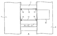
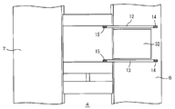
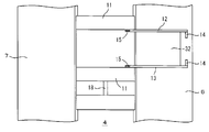
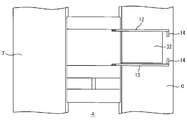
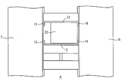
- the top view which shows the conveyance vehicle of an Example, and the shelf on either side Block diagram of transport vehicle controller and motor, and warehouse controller Flow chart showing a grabbing algorithm in the embodiment Top view showing the transport vehicle stopped at the load gripping position A top view showing the transport vehicle with its arms extended A plan view showing the transport vehicle closing the arm and clamping the load A plan view showing the carrier opening the arm and starting to pull in the luggage Top view showing luggage pulled into the transport vehicle Flow chart showing the unloading algorithm A plan view showing the load on which the transport vehicle is traveling Top view showing transport vehicle and luggage stopped at unloading position Top view showing the cargo being unloaded from the transport vehicle to the shelf Plan view showing the unloaded cargo and transport vehicle
- the transport vehicle 4 travels between a pair of left and right shelves 6 and 7, for example, travel rails 8 are provided on the shelves 6 and 7, and travels on the travel rails 8 by the wheels 9 and the travel motor 10 of the transport vehicle 4. .
- the shelves 6 and 7 are provided in multiple stages in the height direction, and the carriage 4 is provided for each stage.
- the carriage 4 is provided with a lifting platform between the shelves having different height levels.
- the delivery of articles may be made freely.
- the shelves 6 and 7 may be on at least one of the left and right sides of the transport vehicle 4.
- the automated warehouse 2 is configured by the entire transport vehicle 4 and the shelves 6 and 7.
- the transport vehicle 4 includes a pair of left and right arm retracting mechanisms 11a and 11b, 12 and 13 are top arms thereof, and the arms 12 and 13 include a pair of hooks 14 and 15 at both front and rear ends.
- the front-rear direction of the arm is the left-right direction when viewed from the transport vehicle 4.
- the direction in which the distance between the top arms 12 and 13 is changed is referred to as an arm opening / closing direction (traveling direction of the transport vehicle 4), and the left-right direction of the transport vehicle 4 is referred to as an arm retracting direction.
- the arm retracting mechanisms 11a and 11b are three-stage arms that move the middle arms 19 and 19 with respect to the base and move the top arms 12 and 13 with respect to the middle arms 19 and 19, but with two or four stages.
- Reference numeral 16 denotes an arm opening / closing motor that changes the distance between the top arms 12 and 13 by moving the arm retracting mechanism 11b back and forth along the traveling direction of the transport vehicle 4. Both arm retracting mechanisms 11 a and 11 b may be moved back and forth along the traveling direction of the transport vehicle 4.
- Reference numeral 17 denotes a nut, which is fixed to the arm retracting mechanism 11b, and the arm opening / closing motor 16 moves the arm retracting mechanism 11b by rotating the screw shaft 18 engaged with the nut 17.
- FIG. 2 shows a control system of the transport vehicle 4.
- the controller 26 of the transport vehicle 4 controls the travel motor 10, the arm opening / closing motor 16, the arm retracting motor 22, and the hook opening / closing motor 24.
- the arm retracting motor 22 is provided in each of the pair of arm retracting mechanisms 11a and 11b
- the hook opening / closing motor 24 is provided in each of the four hooks 14, 14, 15, and 15 to attach the hooks 14 and 15 to each other. Open and close.
- the load sensor 20 detects whether or not the top arms 12 and 13 have clamped the load. For example, when the arm opening / closing motor 16 is closed at a constant speed, the load sensor 20 detects that the output torque rapidly increases due to contact with the load. Alternatively, when the arm opening / closing motor 16 is driven with a constant current, it is detected that the number of rotations of the motor 16 rapidly decreases due to contact with the load.
- the controller 26 controls the traveling motor 10 to the hook opening / closing motor 24 in accordance with the algorithm shown in FIG. 3 and thereafter, communicates with the warehouse controller 28 that manages the entire automatic warehouse 2, and relates to the conveyance of articles from the warehouse controller 28. Receive a directive.
- the warehouse controller 28 includes a shelf file 30, which stores which size baggage is present at which position on the shelves 6 and 7, and the basis of the load along the longitudinal direction of the shelf as the position of the load. The end position is stored, and the size of the load and the width and depth of the load along the longitudinal direction of the shelf are stored. In addition to this, the ID of the package is also stored. Based on the data of the shelf file 30, the controller 26 can grasp at which position and how wide the load is to be grasped.
- the controller 26 When the controller 26 unloads the cargo, the base position of the unloaded cargo, its width, and the ID of the cargo are reported to the warehouse controller 28.
- the warehouse controller 28 updates the shelf file 30 according to this data. . It is not necessary to report the width of the package.
- FIG. 3 shows an algorithm for grasping a load
- FIGS. 4 to 8 schematically show the operations of the top arms 12 and 13.
- the algorithm of FIG. 3 is executed under the control of the controller 26.
- the transport vehicle is notified from the warehouse controller of the base end position along the longitudinal direction of the shelves 6 and 7 and the width of the load 32 of the load 32 to be held, and stops at a position suitable for the load holding.
- the interval between the top arms 12 and 13 is set to be slightly larger than the width of the load, both the hooks 14 and 15 are opened, and at least the hook 14 on the load 32 side (tip side) is opened.
- the clearance of the top arms 12 and 13 with respect to the load width at this time is, for example, about 5 to 30 mm (FIG. 4).
- the top arms 12 and 13 are moved forward and protruded from the transport vehicle 4. At this time, the distance between the top arms 12 and 13 is larger than the width of the load 32. It will not get caught ( Figure 5).
- Figure 5 the space between the top arms 12 and 13 is narrowed, and the load 32 is clamped.
- the arm opening / closing motor is stopped to prevent excessive pressure from being applied to the luggage. For example, at the same time, at least the hooks 14 and 14 on the front end side in the unloading direction are closed (FIG. 6).
- FIG. 9 shows the unloading algorithm
- FIGS. 10 to 13 schematically show the operations of the top arms 12 and 13 during the unloading process. 9 is executed under the control of the controller 26.
- the transport vehicle 4 travels to the unloading position, and this position is notified from the warehouse controller 28. Close the left and right hooks 14, 14, 15, and 15 and move the top arm 13 to the load 32 side so that the load 32 does not sway or protrude from the transfer vehicle 4 to the left or right during traveling. Then, the luggage 32 is clamped by the top arms 12 and 13.
- the top arm 13 is moved backward in the traveling direction. For example, a gap of about 3 to 15 mm is left between the baggage 32 and the baggage 32 (FIG. 11).
- the hook 15 at the front end side in the unloading direction is opened, and the top arms 12 and 13 are moved in the unloading direction so as to protrude from the transport vehicle 4 (FIG. 12).
- the hook 15 on the front end side in the unloading direction may be opened, for example, until the top arms 12 and 13 start retreating. Strictly speaking, when the top arms 12 and 13 retreat, the hooks 15 pass the position of the load 32. Open by.
- the top arms 12 and 13 are moved back onto the transport vehicle 4 with the hooks 14 and 15 opened.
- the hook 14 may be open or closed as long as the next position where the load is grasped is the same shelf 7 as the previous unloading. If the position at which the load is next grasped is the shelf 6 opposite to the previous unloading, the hook 14 is opened until the next load grasping operation, for example, the top arms 12 and 13 are opened simultaneously with the retreat. This is because if the hook 14 is opened while the hook 14 is in contact with the luggage 32, there is a risk of rubbing against the luggage.
- the article 32 is not caught on the top arms 12 and 13 when unloading. Further, since the load is clamped by the top arms 12 and 13 during traveling, the position does not shift or vibrate. Further, since the hooks 14 and 15 are closed, the luggage does not protrude from the transport vehicle 4. In addition, since the loaded load is unloaded by the running clamp, the load can be unloaded at an accurate position, and the position of the load is not ambiguous.
Landscapes
- Engineering & Computer Science (AREA)
- Mechanical Engineering (AREA)
- Warehouses Or Storage Devices (AREA)
Abstract
Description
この発明の補助的な課題は、搬送車上での荷物の位置ずれ、あるいは搬送車からのはみ出しを防ぐことにある。
この発明の補助的な課題は更に、荷物をアームに引っ掛けずに、正確な位置へ荷下ろしすることにある。
前記左右一対のアームは、アームの前後両端に開閉自在なフックを備え、
前記搬送車は、前記左右一対のアームの間隔を変更するアーム開閉機構と、
アームとアーム開閉機構及びフックを制御するコントローラとを備え、
前記コントローラは、荷掴み時に、
搬送車側から見て荷掴み方向に沿って先端側のフックを開いている状態に制御しながら、先端側のフックが荷物を越える位置まで、左右一対のアームを搬送車から突き出すように前進させるようにアームを制御し、
前進した左右一対のアームを閉じて荷物をクランプし、クランプ後に左右一対のアームを開くことにより、荷物と左右一対のアームの少なくとも一方の間に隙間を空けるようにアーム開閉機構を制御し、
荷物を搬送車上へ引き込むため、前記先端側のフックを閉じている状態に制御しながら、左右一対のアームを後退させるようにアームを制御するように構成されていることを特徴とする。
このようにすると、走行中の荷物の位置ずれ、振動等を抑制できる。
荷掴み時に、搬送車側から見て荷掴み方向に沿って先端側のフックを開いた状態で、先端側のフックが荷物を越える位置まで、左右一対のアームを搬送車から突き出すように前進させるステップと、
次いで左右一対のアームを閉じて荷物をクランプするステップと、
クランプ後に左右一対のアームを開き、荷物と左右一対のアームの少なくとも一方の間に隙間を空け、更に前記先端側のフックを閉じた状態で、左右一対のアームを後退させることにより、荷物を搬送車上へ引き込むステップとを、前記コントローラの制御下に実行することを特徴とする。
9 車輪 10 走行モータ 11a,b アーム出退機構
12,13 トップアーム 14,15 フック
16 アーム開閉モータ 17 ナット 18 ネジ軸
19 ミドルアーム 20 荷物センサ
22 アーム出退モータ 24 フック開閉モータ
26 コントローラ 28 倉庫コントローラ
30 棚ファイル 32 荷物
Claims (6)
- 出退自在な左右一対のアームを備えた搬送車であって、
前記左右一対のアームは、アームの前後両端に開閉自在なフックを備え、
前記搬送車は、前記左右一対のアームの間隔を変更するアーム開閉機構と、
アームとアーム開閉機構及びフックを制御するコントローラとを備え、
前記コントローラは、荷掴み時に、
搬送車側から見て荷掴み方向に沿って先端側のフックを開いている状態に制御しながら、先端側のフックが荷物を越える位置まで、左右一対のアームを搬送車から突き出すように前進させるようにアームを制御し、
前進した左右一対のアームを閉じて荷物をクランプし、クランプ後に左右一対のアームを開くことにより、荷物と左右一対のアームの少なくとも一方の間に隙間を空けるようにアーム開閉機構を制御し、
荷物を搬送車上へ引き込むため、前記先端側のフックを閉じている状態に制御しながら、左右一対のアームを後退させるようにアームを制御するように構成されていることを特徴とする、搬送車。 - 前記コントローラは、搬送車の走行中は左右一対のアームにより荷物をクランプするように、アーム開閉機構を制御するように構成されていることを特徴とする、請求項1の搬送車。
- 前記コントローラは、搬送車の走行中は、前後のフックを閉じるようにフックを制御するように構成されていることを特徴とする、請求項2の搬送車。
- 前記コントローラは荷下ろし時に、左右一対のアームの少なくとも一方と荷物との間に隙間を空けるようにアーム開閉機構を制御し、搬送車から見て荷下ろし方向に沿って基端側のフックを閉じている状態に制御し、かつ左右一対のアームを搬送車から突き出すように前進させるように左右一対のアームを制御するように構成されている、ことを特徴とする、請求項1の搬送車。
- 前後両端に開閉自在なフックを備え、かつ出退自在な左右一対のアームとコントローラとを備えた搬送車による荷物の搬送方法であって、
荷掴み時に、搬送車側から見て荷掴み方向に沿って先端側のフックを開いた状態で、先端側のフックが荷物を越える位置まで、左右一対のアームを搬送車から突き出すように前進させるステップと、
次いで左右一対のアームを閉じて荷物をクランプするステップと、
クランプ後に左右一対のアームを開き、荷物と左右一対のアームの少なくとも一方の間に隙間を空け、更に前記先端側のフックを閉じた状態で、左右一対のアームを後退させることにより、荷物を搬送車上へ引き込むステップとを、前記コントローラの制御下に実行することを特徴とする、搬送車による荷物の搬送方法。 - 荷下ろし時に、左右一対のアームの少なくとも一方と荷物との間に隙間を空け、搬送車から見て荷下ろし方向に沿って基端側のフックが閉じている状態で、左右一対のアームを搬送車から突き出すように前進させるステップを、前記コントローラの制御下に実行することを特徴とする、請求項5の搬送車による搬送方法。
Priority Applications (4)
| Application Number | Priority Date | Filing Date | Title |
|---|---|---|---|
| KR1020137007930A KR101414188B1 (ko) | 2010-08-31 | 2011-03-03 | 반송차 및 반송 방법 |
| JP2012531707A JP5448120B2 (ja) | 2010-08-31 | 2011-03-03 | 搬送車及び搬送方法 |
| US13/816,963 US9327902B2 (en) | 2010-08-31 | 2011-03-03 | Conveyor vehicle and conveyor method |
| CN201180038548.XA CN103068696B (zh) | 2010-08-31 | 2011-03-03 | 搬送车及搬送方法 |
Applications Claiming Priority (2)
| Application Number | Priority Date | Filing Date | Title |
|---|---|---|---|
| JP2010-194660 | 2010-08-31 | ||
| JP2010194660 | 2010-08-31 |
Publications (1)
| Publication Number | Publication Date |
|---|---|
| WO2012029339A1 true WO2012029339A1 (ja) | 2012-03-08 |
Family
ID=45772456
Family Applications (1)
| Application Number | Title | Priority Date | Filing Date |
|---|---|---|---|
| PCT/JP2011/054894 Ceased WO2012029339A1 (ja) | 2010-08-31 | 2011-03-03 | 搬送車及び搬送方法 |
Country Status (6)
| Country | Link |
|---|---|
| US (1) | US9327902B2 (ja) |
| JP (1) | JP5448120B2 (ja) |
| KR (1) | KR101414188B1 (ja) |
| CN (1) | CN103068696B (ja) |
| TW (1) | TWI483880B (ja) |
| WO (1) | WO2012029339A1 (ja) |
Cited By (13)
| Publication number | Priority date | Publication date | Assignee | Title |
|---|---|---|---|---|
| WO2014038308A1 (ja) * | 2012-09-05 | 2014-03-13 | 村田機械株式会社 | 移載装置 |
| JP2016155651A (ja) * | 2015-02-24 | 2016-09-01 | 村田機械株式会社 | 移載装置 |
| JP2017007786A (ja) * | 2015-06-19 | 2017-01-12 | 村田機械株式会社 | 移載装置 |
| JP2017218251A (ja) * | 2016-06-03 | 2017-12-14 | 村田機械株式会社 | 搬送車 |
| JP2018002320A (ja) * | 2016-06-27 | 2018-01-11 | 村田機械株式会社 | 走行式移載装置 |
| US9908699B2 (en) | 2016-04-27 | 2018-03-06 | Murata Machinery, Ltd. | Transport vehicle |
| JP2019529288A (ja) * | 2016-09-27 | 2019-10-17 | サヴォワ | サイズ不定荷物把持装置および対応する把持幅変更方法 |
| JP2019189392A (ja) * | 2018-04-24 | 2019-10-31 | 株式会社ダイフク | 物品搬送車 |
| WO2020203097A1 (ja) * | 2019-03-29 | 2020-10-08 | 株式会社ダイフク | 移載装置(transfer device) |
| JP2021041874A (ja) * | 2019-09-13 | 2021-03-18 | 日本車輌製造株式会社 | 台車載せ降ろし機構を備える鉄道車両用トラバーサ |
| JP2022546975A (ja) * | 2019-09-09 | 2022-11-10 | ベイジン・ジンドン・チアンシ・テクノロジー・カンパニー・リミテッド | 倉庫シャトル車両 |
| WO2024154396A1 (ja) | 2023-01-20 | 2024-07-25 | 村田機械株式会社 | 自動倉庫 |
| WO2024190084A1 (ja) | 2023-03-10 | 2024-09-19 | 村田機械株式会社 | 自動倉庫 |
Families Citing this family (4)
| Publication number | Priority date | Publication date | Assignee | Title |
|---|---|---|---|---|
| EP2620391B1 (de) * | 2012-01-30 | 2014-06-18 | CareFusion Germany 326 GmbH | Verfahren zum Auslagern von Arzneimittelpackungen |
| US20150321845A1 (en) * | 2012-09-05 | 2015-11-12 | Murata Machinery, Ltd. | Transfer device |
| CN110615378B (zh) * | 2019-08-06 | 2023-07-25 | 东杰智能科技集团股份有限公司 | 穿梭小车的托盘举升机构上的随动挂钩 |
| JP7396506B2 (ja) * | 2020-09-04 | 2023-12-12 | 村田機械株式会社 | 自動倉庫 |
Citations (3)
| Publication number | Priority date | Publication date | Assignee | Title |
|---|---|---|---|---|
| JPH1087023A (ja) * | 1996-09-11 | 1998-04-07 | Itoki Crebio Corp | 自動倉庫における移動台車の荷物移載装置 |
| JP2002068406A (ja) * | 2000-08-31 | 2002-03-08 | Itoki Crebio Corp | 自動倉庫の二重格納防止装置 |
| JP2005219833A (ja) * | 2004-02-03 | 2005-08-18 | Toyota Industries Corp | 自動倉庫の制御装置 |
Family Cites Families (10)
| Publication number | Priority date | Publication date | Assignee | Title |
|---|---|---|---|---|
| US4597710A (en) * | 1984-11-28 | 1986-07-01 | Athey Products Corporation | Trash collection vehicle side-loading apparatus |
| US4723532A (en) * | 1986-06-16 | 1988-02-09 | Bonatex Inc. | Football throwing machine |
| JP3137999B2 (ja) * | 1991-04-12 | 2001-02-26 | 株式会社アマダ | 加工機に対するワーク搬出入装置 |
| DE4409110C1 (de) * | 1994-03-17 | 1995-07-13 | Hurdis Building Trust Reg | Ladewagen |
| JP3447449B2 (ja) * | 1995-11-17 | 2003-09-16 | 株式会社イトーキクレビオ | 自動倉庫 |
| JPH11278607A (ja) | 1998-03-25 | 1999-10-12 | Murata Mach Ltd | 自動倉庫 |
| US6644906B2 (en) * | 2000-01-31 | 2003-11-11 | Bayne Machine Works, Inc. | Self-adapting refuse receptacle lift with low profile |
| US20080089764A1 (en) * | 2006-10-12 | 2008-04-17 | Felix Vistro | Combined truck and garbage container sanitizing system and associated method |
| US8079799B2 (en) * | 2007-05-09 | 2011-12-20 | Petersen Industries, Inc | Apparatus and method for lifting containers |
| TWM345803U (en) * | 2008-06-06 | 2008-12-01 | Usun Technology Co Ltd | Article loading/unloading device |
-
2011
- 2011-03-03 WO PCT/JP2011/054894 patent/WO2012029339A1/ja not_active Ceased
- 2011-03-03 KR KR1020137007930A patent/KR101414188B1/ko not_active Expired - Fee Related
- 2011-03-03 JP JP2012531707A patent/JP5448120B2/ja active Active
- 2011-03-03 US US13/816,963 patent/US9327902B2/en active Active
- 2011-03-03 CN CN201180038548.XA patent/CN103068696B/zh not_active Expired - Fee Related
- 2011-08-29 TW TW100130857A patent/TWI483880B/zh not_active IP Right Cessation
Patent Citations (3)
| Publication number | Priority date | Publication date | Assignee | Title |
|---|---|---|---|---|
| JPH1087023A (ja) * | 1996-09-11 | 1998-04-07 | Itoki Crebio Corp | 自動倉庫における移動台車の荷物移載装置 |
| JP2002068406A (ja) * | 2000-08-31 | 2002-03-08 | Itoki Crebio Corp | 自動倉庫の二重格納防止装置 |
| JP2005219833A (ja) * | 2004-02-03 | 2005-08-18 | Toyota Industries Corp | 自動倉庫の制御装置 |
Cited By (24)
| Publication number | Priority date | Publication date | Assignee | Title |
|---|---|---|---|---|
| WO2014038308A1 (ja) * | 2012-09-05 | 2014-03-13 | 村田機械株式会社 | 移載装置 |
| CN104428218B (zh) * | 2012-09-05 | 2015-11-25 | 村田机械株式会社 | 移载装置 |
| JPWO2014038308A1 (ja) * | 2012-09-05 | 2016-08-08 | 村田機械株式会社 | 移載装置 |
| US9598236B2 (en) | 2012-09-05 | 2017-03-21 | Murata Machinery, Ltd. | Transfer device |
| TWI602767B (zh) * | 2012-09-05 | 2017-10-21 | Murata Machinery Ltd | Transfer device |
| JP2016155651A (ja) * | 2015-02-24 | 2016-09-01 | 村田機械株式会社 | 移載装置 |
| JP2017007786A (ja) * | 2015-06-19 | 2017-01-12 | 村田機械株式会社 | 移載装置 |
| US9908699B2 (en) | 2016-04-27 | 2018-03-06 | Murata Machinery, Ltd. | Transport vehicle |
| JP2017218251A (ja) * | 2016-06-03 | 2017-12-14 | 村田機械株式会社 | 搬送車 |
| JP2018002320A (ja) * | 2016-06-27 | 2018-01-11 | 村田機械株式会社 | 走行式移載装置 |
| JP2019529288A (ja) * | 2016-09-27 | 2019-10-17 | サヴォワ | サイズ不定荷物把持装置および対応する把持幅変更方法 |
| JP2019189392A (ja) * | 2018-04-24 | 2019-10-31 | 株式会社ダイフク | 物品搬送車 |
| WO2020203097A1 (ja) * | 2019-03-29 | 2020-10-08 | 株式会社ダイフク | 移載装置(transfer device) |
| US12103769B2 (en) | 2019-03-29 | 2024-10-01 | Daifuku Co., Ltd. | Transfer device |
| JP2022546975A (ja) * | 2019-09-09 | 2022-11-10 | ベイジン・ジンドン・チアンシ・テクノロジー・カンパニー・リミテッド | 倉庫シャトル車両 |
| JP7443494B2 (ja) | 2019-09-09 | 2024-03-05 | ベイジン・ジンドン・チアンシ・テクノロジー・カンパニー・リミテッド | 倉庫シャトル車両 |
| JP2021041874A (ja) * | 2019-09-13 | 2021-03-18 | 日本車輌製造株式会社 | 台車載せ降ろし機構を備える鉄道車両用トラバーサ |
| JP7321646B2 (ja) | 2019-09-13 | 2023-08-07 | 日本車輌製造株式会社 | 台車載せ降ろし機構を備える鉄道車両用トラバーサ |
| WO2024154396A1 (ja) | 2023-01-20 | 2024-07-25 | 村田機械株式会社 | 自動倉庫 |
| KR20250116091A (ko) | 2023-01-20 | 2025-07-31 | 무라다기카이가부시끼가이샤 | 자동 창고 |
| EP4647369A1 (en) | 2023-01-20 | 2025-11-12 | Murata Machinery, Ltd. | Automated warehouse |
| WO2024190084A1 (ja) | 2023-03-10 | 2024-09-19 | 村田機械株式会社 | 自動倉庫 |
| KR20250135292A (ko) | 2023-03-10 | 2025-09-12 | 무라다기카이가부시끼가이샤 | 자동 창고 |
| EP4678565A1 (en) | 2023-03-10 | 2026-01-14 | Murata Machinery, Ltd. | Automated warehouse |
Also Published As
| Publication number | Publication date |
|---|---|
| TW201217245A (en) | 2012-05-01 |
| CN103068696B (zh) | 2014-09-10 |
| TWI483880B (zh) | 2015-05-11 |
| CN103068696A (zh) | 2013-04-24 |
| KR101414188B1 (ko) | 2014-07-01 |
| US9327902B2 (en) | 2016-05-03 |
| US20130142600A1 (en) | 2013-06-06 |
| JPWO2012029339A1 (ja) | 2013-10-28 |
| JP5448120B2 (ja) | 2014-03-19 |
| KR20130066678A (ko) | 2013-06-20 |
Similar Documents
| Publication | Publication Date | Title |
|---|---|---|
| JP5448120B2 (ja) | 搬送車及び搬送方法 | |
| CN107667061B (zh) | 用于将件货存入货架中的方法和仓库系统 | |
| CN104619614B (zh) | 移载装置 | |
| JP5928596B2 (ja) | 移載装置 | |
| CN106882553A (zh) | 物品移载装置及物品输送设备 | |
| JP4378655B2 (ja) | 物品処理設備 | |
| JP6056707B2 (ja) | 物品移載装置及び搬送設備 | |
| TW202440434A (zh) | 物品搬送裝置 | |
| CN101259918A (zh) | 物品搬送设备 | |
| JP7298589B2 (ja) | 物品収容設備 | |
| CN113614005B (zh) | 移载装置 | |
| CN113544068A (zh) | 物品搬运车 | |
| JP5910723B2 (ja) | 移載装置及び移載装置の制御方法 | |
| CN219136289U (zh) | 货叉组件及仓储机器人 | |
| JP2020050001A (ja) | 台車搬送装置 | |
| CN114684744A (zh) | 货叉组件及搬运机器人 | |
| CN207917738U (zh) | 一种仓储自动取料机 | |
| JP2001220002A (ja) | 自動搬送システム | |
| JP6694614B2 (ja) | 物品移載装置及び物品移載システム | |
| JP2014173367A (ja) | 二輪車駐輪装置 | |
| JP2005219833A (ja) | 自動倉庫の制御装置 | |
| US20210114756A1 (en) | Tray sleever | |
| JP5445397B2 (ja) | 移載装置 | |
| JP2023167984A (ja) | 自動倉庫 | |
| JP7515790B2 (ja) | 自動倉庫 |
Legal Events
| Date | Code | Title | Description |
|---|---|---|---|
| WWE | Wipo information: entry into national phase |
Ref document number: 201180038548.X Country of ref document: CN |
|
| 121 | Ep: the epo has been informed by wipo that ep was designated in this application |
Ref document number: 11821357 Country of ref document: EP Kind code of ref document: A1 |
|
| WWE | Wipo information: entry into national phase |
Ref document number: 2012531707 Country of ref document: JP |
|
| WWE | Wipo information: entry into national phase |
Ref document number: 13816963 Country of ref document: US |
|
| NENP | Non-entry into the national phase |
Ref country code: DE |
|
| ENP | Entry into the national phase |
Ref document number: 20137007930 Country of ref document: KR Kind code of ref document: A |
|
| 122 | Ep: pct application non-entry in european phase |
Ref document number: 11821357 Country of ref document: EP Kind code of ref document: A1 |