WO2012026285A1 - 間接加熱型回転乾燥機 - Google Patents
間接加熱型回転乾燥機 Download PDFInfo
- Publication number
- WO2012026285A1 WO2012026285A1 PCT/JP2011/067407 JP2011067407W WO2012026285A1 WO 2012026285 A1 WO2012026285 A1 WO 2012026285A1 JP 2011067407 W JP2011067407 W JP 2011067407W WO 2012026285 A1 WO2012026285 A1 WO 2012026285A1
- Authority
- WO
- WIPO (PCT)
- Prior art keywords
- rotating cylinder
- axis
- heating
- rotary dryer
- workpiece
- Prior art date
- Legal status (The legal status is an assumption and is not a legal conclusion. Google has not performed a legal analysis and makes no representation as to the accuracy of the status listed.)
- Ceased
Links
Images


Classifications
-
- F—MECHANICAL ENGINEERING; LIGHTING; HEATING; WEAPONS; BLASTING
- F26—DRYING
- F26B—DRYING SOLID MATERIALS OR OBJECTS BY REMOVING LIQUID THEREFROM
- F26B17/00—Machines or apparatus for drying materials in loose, plastic, or fluidised form, e.g. granules, staple fibres, with progressive movement
- F26B17/30—Machines or apparatus for drying materials in loose, plastic, or fluidised form, e.g. granules, staple fibres, with progressive movement with movement performed by rotary or oscillating containers; with movement performed by rotary floors
- F26B17/32—Machines or apparatus for drying materials in loose, plastic, or fluidised form, e.g. granules, staple fibres, with progressive movement with movement performed by rotary or oscillating containers; with movement performed by rotary floors the movement being in a horizontal or slightly inclined plane
-
- F—MECHANICAL ENGINEERING; LIGHTING; HEATING; WEAPONS; BLASTING
- F26—DRYING
- F26B—DRYING SOLID MATERIALS OR OBJECTS BY REMOVING LIQUID THEREFROM
- F26B11/00—Machines or apparatus for drying solid materials or objects with movement which is non-progressive
- F26B11/02—Machines or apparatus for drying solid materials or objects with movement which is non-progressive in moving drums or other mainly-closed receptacles
- F26B11/04—Machines or apparatus for drying solid materials or objects with movement which is non-progressive in moving drums or other mainly-closed receptacles rotating about a horizontal or slightly-inclined axis
- F26B11/0404—Machines or apparatus for drying solid materials or objects with movement which is non-progressive in moving drums or other mainly-closed receptacles rotating about a horizontal or slightly-inclined axis with internal subdivision of the drum, e.g. for subdividing or recycling the material to be dried
- F26B11/0409—Machines or apparatus for drying solid materials or objects with movement which is non-progressive in moving drums or other mainly-closed receptacles rotating about a horizontal or slightly-inclined axis with internal subdivision of the drum, e.g. for subdividing or recycling the material to be dried the subdivision consisting of a plurality of substantially radially oriented internal walls, e.g. forming multiple sector-shaped chambers
-
- F—MECHANICAL ENGINEERING; LIGHTING; HEATING; WEAPONS; BLASTING
- F26—DRYING
- F26B—DRYING SOLID MATERIALS OR OBJECTS BY REMOVING LIQUID THEREFROM
- F26B11/00—Machines or apparatus for drying solid materials or objects with movement which is non-progressive
- F26B11/02—Machines or apparatus for drying solid materials or objects with movement which is non-progressive in moving drums or other mainly-closed receptacles
- F26B11/04—Machines or apparatus for drying solid materials or objects with movement which is non-progressive in moving drums or other mainly-closed receptacles rotating about a horizontal or slightly-inclined axis
- F26B11/0445—Machines or apparatus for drying solid materials or objects with movement which is non-progressive in moving drums or other mainly-closed receptacles rotating about a horizontal or slightly-inclined axis having conductive heating arrangements, e.g. heated drum wall
- F26B11/045—Machines or apparatus for drying solid materials or objects with movement which is non-progressive in moving drums or other mainly-closed receptacles rotating about a horizontal or slightly-inclined axis having conductive heating arrangements, e.g. heated drum wall using heated internal elements, e.g. which move through or convey the materials to be dried
-
- F—MECHANICAL ENGINEERING; LIGHTING; HEATING; WEAPONS; BLASTING
- F26—DRYING
- F26B—DRYING SOLID MATERIALS OR OBJECTS BY REMOVING LIQUID THEREFROM
- F26B2200/00—Drying processes and machines for solid materials characterised by the specific requirements of the drying good
- F26B2200/02—Biomass, e.g. waste vegetative matter, straw
-
- F—MECHANICAL ENGINEERING; LIGHTING; HEATING; WEAPONS; BLASTING
- F26—DRYING
- F26B—DRYING SOLID MATERIALS OR OBJECTS BY REMOVING LIQUID THEREFROM
- F26B2200/00—Drying processes and machines for solid materials characterised by the specific requirements of the drying good
- F26B2200/24—Wood particles, e.g. shavings, cuttings, saw dust
Definitions
- the present invention relates to an indirect heating type rotary dryer that reduces the number of heating tubes that do not come into contact with an object to be processed and saves energy by reducing the power for rotation even when the filling rate is increased.
- it can be applied to an apparatus for drying or cooling an object to be processed.
- a steam tube dryer (hereinafter also referred to as STD as appropriate), which is an indirect heating rotary dryer, includes a rotatable rotating cylinder having a length of 10 m to 30 m.
- the rotating cylinder is dried in the rotating cylinder by the heating steam as the external heat for drying.
- the object to be processed is rotated by rotating a rotating cylinder while drying by bringing wet powder or granular powder to be processed into contact with a heating tube into which steam or the like is sent as a heat medium.
- the workpiece is continuously dried while being sequentially moved to the discharge port.
- this indirect heating type rotary dryer can be enlarged and is cheaper than the indirect heating type disk dryer.
- the indirect heating type rotary dryer has been conventionally used as an apparatus for drying or cooling a workpiece in various directions.
- a plurality of heating tubes 111 are arranged in parallel with the axis of the rotary cylinder.
- the upper limit value of the filling rate of the object to be processed H in the rotating cylinder is due to the position where the object to be processed H is charged. , Approximately 30%.
- the upper limit of the filling rate of the object to be processed is approximately 30% as described above, even if the heating tube is arranged in the vicinity of the center in the rotating cylinder, there is almost no contact with the object to be processed. For this reason, in the conventional apparatus, heating tubes are not arranged in the vicinity of the axis of the rotating cylinder, which is inefficient and low in economic efficiency.
- heating tubes are not arranged in the vicinity of the axis of the rotating cylinder, which is inefficient and low in economic efficiency.
- the present invention provides an indirect heating type rotary dryer that reduces the number of heating tubes that do not come into contact with the object to be processed and saves energy by reducing the power for rotation even when the filling rate is increased.
- the purpose is to do.
- the indirect heating type rotary dryer according to the present invention is a rotating cylinder that is rotated around an axis, can be loaded with a workpiece from one end side, and can discharge the workpiece from the other end side;
- a plurality of heating tubes each disposed in the rotating cylinder in parallel with the axis of the rotating cylinder and heating an object to be processed in the rotating cylinder;
- a plurality of dividing walls provided in the rotating cylinder and dividing the internal space of the rotating cylinder into a plurality of small spaces respectively extending along the axis of the rotating cylinder; It is provided with.
- the object to be processed is inserted from one end side of the rotating cylinder rotated around the axis, and the object to be processed is discharged from the other end side of the rotating cylinder.
- a plurality of heating tubes respectively disposed in the rotating cylinder in parallel with the axis of the rotating cylinder heats the object to be processed in the rotating cylinder.
- the plurality of dividing walls are provided in the rotating cylinder, the plurality of dividing walls divide the internal space of the rotating cylinder into a plurality of small spaces that respectively extend along the axis of the rotating cylinder. It is supposed to be a structure.
- the object to be processed can be distributed in each small space and supplied into the rotating cylinder.
- the filling rate of the objects to be processed can be increased, and the objects to be processed come into contact with more heating tubes, so that the heating tubes can be effectively used.
- the rotating cylinder can be reduced in size, leading to cost reduction of the indirectly heated rotary dryer.
- the objects to be processed are distributed and supplied to each small space, the objects to be processed only move within each small space even if the filling rate is increased, and the objects to be processed are lifted up in the rotating cylinder. As the power decreases, the weight of the objects to be processed in each small space is balanced. As a result, the power required to rotate the rotating cylinder can be reduced.
- the heating tube that does not come into contact with the object to be processed is increased by increasing the filling rate, but also energy is saved by reducing power even if the filling rate is increased, resulting in high economic efficiency. It becomes an indirect heating type rotary dryer which has.
- the indirect heating rotary dryer according to the present invention also includes a charging device for charging an object to be processed into the rotating cylinder, A cylindrical central cover disposed in the vicinity of the axis of the rotating cylinder in a size corresponding to a seal portion that seals a gap between the charging device and the rotating cylinder; And each of the dividing walls has a configuration in which the outer peripheral surface of the center cover and the inner peripheral surface of the rotating cylinder are connected to each other.
- the heating tube interferes with the charging device for charging the workpiece into the rotating cylinder. Become. For this reason, it is necessary to bend the heating tube in the vicinity of the charging device so as not to interfere with the charging device, and as a result, the manufacturing cost of the indirect heating rotary dryer may be increased.
- the dividing wall is simply provided, but also the central cover having a size corresponding to the seal portion that seals the gap between the charging device and the rotating cylinder is provided on the rotating cylinder. It is arranged in the vicinity of the shaft center, and the dividing wall is structured to connect the outer peripheral surface of the center cover and the inner peripheral surface of the rotating cylinder, and the cross section of each small space is closed in a substantially fan shape. .
- the dead space where the heating tube and the object to be processed in each small space do not contact can be reduced, and the contact efficiency can be improved. .
- the center cover is extended to the vicinity of the charging device for charging the workpiece into the rotating cylinder, Screw-shaped blades that reach the inner peripheral surface of the rotating cylinder are installed on the outer peripheral surface of the extended center cover, It has a configuration in which a cutout portion for removing a part of the central cover where the screw-shaped blades are installed is provided.
- a cutout portion is provided by removing a portion of the central cover where the screw-shaped blades are installed, and the workpiece is supplied into each small space divided through the cutout portion, and the rotating cylinder
- the screw-like blades By sending the screw-like blades to the inner side of the small space by the rotation of the rotating blades, the objects to be processed enter the small spaces almost uniformly with the rotation of the rotating cylinder.
- each heating tube is arranged in parallel with the axis of the rotating cylinder at a position separated from the axis of the rotating cylinder by a length of 15% or more of the radius of the rotating cylinder. It has a configuration that.
- the upper limit value of the filling rate of the object to be processed is approximately 30% (up to approximately 30% or more of the radius of the rotating cylinder). For this reason, even if the heating tube is arranged in the vicinity of the center in the rotating cylinder, there is little effect that it hardly contacts the object to be processed or that the contact time with the object to be processed per one rotation of the rotating cylinder is short. For this reason, the heating tube was not arranged in the vicinity of the axial center of 30% or less of the radius of the rotating cylinder.
- the length is 15% or more of the radius of the rotating cylinder (the size corresponding to the seal portion that seals the gap between the charging device and the rotating cylinder).
- the indirect heating rotary dryer according to the present invention has a configuration in which a heat medium is supplied into the dividing wall or the central cover.
- the workpiece is heated not only by the heating tube but also by the dividing wall and the central cover. Efficiency will be improved.
- the number of heating tubes that do not come into contact with the object to be processed is reduced, and indirect heating type rotary drying that saves energy by reducing the power for rotation even when the filling rate is increased. Machine can be provided.
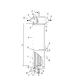
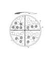
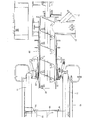
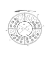
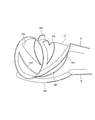
- FIG. 1 is a partially broken perspective view of a rotary heat treatment apparatus according to a first embodiment of the present invention. It is a front fragmentary sectional view of the rotary heat processing apparatus which concerns on the 1st Embodiment of this invention. It is a cross-sectional view of the rotary cylinder applied to the rotary heat treatment apparatus according to the first embodiment of the present invention. It is sectional drawing which shows the charging device periphery of the rotary heat processing apparatus which concerns on the 2nd Embodiment of this invention. It is a cross-sectional view of the rotary cylinder applied to the rotary heat treatment apparatus according to the third embodiment of the present invention.
- FIG. 1 A first embodiment of an indirectly heated rotary dryer according to the present invention will be described below with reference to the drawings.
- an example of the indirect heating rotary dryer which is also referred to as a steam tube dryer including the embodiment of the present invention is shown in FIG. 1 and FIG.
- the overall configuration of the present embodiment will be described in advance.
- the indirect heating rotary dryer 1 shown in FIGS. 1 and 2 includes a plurality of heating pipes 11 arranged in parallel with the axis C between both end plates in a rotating cylinder 10 that is rotatable around the axis C. Has been.
- the superheat pipe 11 is supplied with heating steam KJ as a heat medium through the heat medium inlet pipe 61 attached to the rotary joint 60 and is circulated to each of the heat pipes 11.
- the heated steam KJ drain is discharged through 62.
- the indirect heating rotary dryer 1 is provided with a charging device 20 having a screw 22 and the like for charging the workpiece H into the rotary cylinder 10.
- the wet powder or granular powder which is the material to be processed H, which is introduced from one end side into the rotary cylinder 10 from the charging port 21 of the charging device 20 comes into contact with the heating tube 11 heated by the heating steam KJ. dry.
- the rotating cylinder 10 is installed with a downward slope, it is moved smoothly in the direction toward the discharge port 12 so that the workpiece H is continuously discharged from the other end side of the rotating cylinder 10. ing.
- the rotary cylinder 10 is installed on a base 31 and is provided with two sets of support rollers 30, 30 arranged in parallel with the axis C of the rotary cylinder 10 and spaced apart from each other. It is supported via a tire 14.
- the width between the two sets of support rollers 30 and 30 and the longitudinal inclination angle thereof are selected in accordance with the downward gradient and diameter of the rotary cylinder 10.
- a driven gear 50 is provided around the rotating cylinder 10 in order to rotate the rotating cylinder 10.
- the drive gear 53 meshes with the driven gear 50, and the rotational force of the prime mover 51 is transmitted through the speed reducer 52, and the rotating cylinder 10 is rotated about the axis C through the drive gear 53 and the driven gear 50.
- the carrier gas CG is introduced into the rotary cylinder 10 from the carrier gas inlet 71. These carrier gases CG are discharged from the carrier gas discharge port 70 along with the vapor obtained by evaporating the water contained in the wet powder or granular powder that is the workpiece H.
- the whole structure of the said indirect heating type rotary dryer 1 is an example, and this invention is not limited by the said structure.
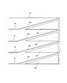
- each dividing wall 16 is a section from the vicinity of the charging device 20 for charging the workpiece H to the vicinity of the discharge port 12 for discharging the workpiece H in the axial direction of the rotary cylinder 10.
- S is continuously installed during S, and each small space K is located in the same range.
- the partition wall 16 has a blade 16A formed in a screw shape in the vicinity of the charging device 20 as in the present embodiment. preferable.
- each heating tube 11 is divided into four small spaces K between the end plates at both ends of the rotating cylinder 10 as shown in FIG.
- the heating tubes 11 are located at positions in the rotary cylinder 10 at least separated from the axis C of the rotary cylinder 10 by a length R2 of 15% or more with respect to the radius R1 of the rotary cylinder 10.
- three rows are arranged so as to extend in parallel with the axis C.
- the heating steam KJ is supplied to these heating pipes 11 as a heat medium, and the heating pipes 11 are exchanged with the workpiece H in the rotary cylinder 10 with the rotation in the direction of the arrow shown in FIG.
- the workpiece H is heated and dried.
- a charging device 20 for charging the workpiece H into the rotating cylinder 10 is provided at one end of the rotating cylinder 10. Yes, the workpiece H is loaded from one end side of the rotating cylinder 10 that is rotatable around the axis C, and the workpiece H is discharged from the other end side of the rotating cylinder 10. At this time, the heating tubes 11 disposed in the rotating cylinder 10 in parallel with the axis C of the rotating cylinder 10 heat the workpiece H in the rotating cylinder 10.
- the four dividing walls 16 shown in FIG. 3 are provided in the rotating cylinder 10, and the dividing walls 16 are provided near the axis C of the rotating cylinder 10 and the inner peripheral side of the rotating cylinder 10. It is made the structure which connects between. Accordingly, the four divided walls are divided into four small spaces K extending along the axis C of the rotating cylinder 10 so that the inner space of the rotating cylinder 10 is divided into a substantially sector shape in the cross section of the rotating cylinder 10. 16 is divided.
- the workpiece H is dispersed in each of the small spaces K and is contained in the rotary cylinder 10. It becomes possible to supply. As a result, the filling rate of the object to be processed H can be increased, and the object to be processed H comes into contact with a larger number of the heating tubes 11 so that the heating tube 11 can be used effectively, while the same amount of objects to be processed is obtained.
- the rotating cylinder 10 can be reduced in size, which leads to a cost reduction of the indirectly heated rotary dryer 1.
- the heating tube 11 that is in contact with the object to be processed H in the heating tube 11 and contributes to heating can be increased to approximately 50% or more, and the drying ability can be improved. Furthermore, as shown in FIG. 3, also in the upper part of the rotating cylinder 10, the heating tube 11 arranged near the axis of the rotating cylinder 10 and the workpiece H come into contact. From this, even if it is the indirect heating type rotary dryer 1 of the same magnitude
- the workpieces H are distributed and supplied to the small spaces K, the workpieces H only move in the small spaces K even if the filling rate is increased. The power to lift up the processed material H is reduced. In addition, since the workpieces H are supplied into the respective small spaces K, the workpieces H are dispersed in the rotation cross section shown in FIG. Can reduce the power required.
- the contact area between the heating tube 11 and the workpiece H is increased as compared with the conventional apparatus. it can.
- the filling rate can be improved.
- the size of the indirect heating rotary dryer 1 in the decreasing rate drying section can be reduced. As described above, according to the present embodiment, not only the heating tube 11 that does not come into contact with the workpiece H is increased by increasing the filling rate, but energy can be saved by reducing the power even if the filling rate is increased. It becomes the indirect heating type rotary dryer 1 which has high economical efficiency.
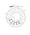
- the indirect heating rotary dryer 1 according to the present embodiment has substantially the same structure as that of the first embodiment, and includes four heating spaces 11, four small spaces K partitioned by four dividing walls 16, and the like. As well. However, in the present embodiment, as shown in FIG. 4, in addition to the arrangement of the heating tubes 11, the charging port 21 and the carrier gas inlet 71 of the charging device 20 are slightly different from the first embodiment.
- arranging the heating tube 11 up to the vicinity of the axis C of the rotating cylinder 10 contributes to an increase in the contact area between the workpiece H and the heating tube 11, but The heating tube 11 interferes with the charging device 20 for charging the workpiece H. For this reason, in the first embodiment, it is necessary to bend the heating tube 11 in the vicinity of the charging device 20 so as not to interfere with the charging device 20.
- the cylinder H has a size corresponding to the seal portion 23 that seals a gap between the charging device 20 that charges the workpiece H into the rotating cylinder 10 and the rotating cylinder 10.
- a central cover 18 formed on the rotating cylinder 10 is disposed in the vicinity of the axis C.
- Each partition wall 16 has a structure connecting the outer peripheral surface of the center cover 18 and the inner peripheral surface of the rotary cylinder 10.
- the dividing wall 16 not only the dividing wall 16 is provided, but also from the seal portion 23 corresponding to the seal portion 23 that seals the gap between the charging device 20 and the rotary cylinder 10.
- a central cover 18 having a slightly larger diameter is disposed in the vicinity of the axis C of the rotating cylinder 10.
- the dividing wall 16 has a structure connecting the outer peripheral surface of the center cover 18 and the inner peripheral surface of the rotary cylinder 10, and the cross section of each small space K is closed in a substantially fan shape. Yes.
- the center cover 18 it is possible to prevent the workpiece H from being present in a place where the heating tube 11 in the vicinity of the axis C in the rotary cylinder 10 is not installed. The opportunity to contact the heating tube 11 of the thing H increases.
- the cutout portion 18A is provided by deleting a part of the central cover 18 where the screw-like blade 16A is installed.
- the workpiece H fed into the rotary cylinder 10 from the charging device 20 is supplied into each small space K divided through the notch 18A as the rotary cylinder 10 rotates.
- the workpiece H is fed into the small spaces K by the rotation of the screw-like blades 16 ⁇ / b> A accompanying the rotation of the rotary cylinder 10, so that it enters the small spaces K almost uniformly.
- the supply position of the object to be processed H is higher than the supply position. May be filled at height. For this reason, by providing the screw-shaped blade 16A for feeding the workpiece H to the rotary cylinder 10 in the vicinity of the charging device 20, the workpiece H is forcibly forced by the blade 16A in the small space K divided into a substantially fan shape. Will be sent to.
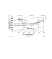
- the ratio of the outer diameter D2 of the central cover 18 and the inner diameter D1 of the rotating cylinder 10 (cover diameter / rotation) when the filling rate is constant.
- the relationship between the cylinder diameter) and the actual contact area ratio is shown in FIG.
- the upper data is a case with a rotating cylinder diameter of 965 mm (rotating cylinder diameter: small)
- the lower data is a case with a rotating cylinder diameter of 3050 mm (rotating cylinder diameter: large).
- the actual contact area between the heating tube 11 and the workpiece H increases.
- the ratio of the outer diameter D2 of the central cover 18 to the inner diameter D1 of the rotary cylinder 10 exceeds 0.6, the space through which the carrier gas CG passes decreases, and at the same time the stirring effect decreases, so the drying capacity decreases. To do.
- the ratio of the outer diameter D2 of the central cover 18 to the inner diameter D1 of the rotary cylinder 10 is less than 0.2, the outer diameter D of the central cover 18 is smaller than the outer diameter of the charging device 20 in most cases.
- the ratio of the outer diameter D2 of the central cover 18 to the inner diameter D1 of the rotary cylinder 10 is preferably in the range of 0.2 to 0.6.
- the heating steam KJ as a heat medium may be supplied to the space KC in the dividing wall 16 and the center cover 18 used in the above embodiment.
- the heating steam KJ may be supplied into the dividing wall 16 or the central cover 18, the workpiece H is heated not only by the heating pipe 11 but also by the dividing wall 16 and the central cover 18. Will be further improved.
- heating steam KJ is supplied into the dividing wall 16, a plurality of plate members are arranged so as to face each other at a fixed distance, or a plurality of pipes are arranged in parallel to form a structure having an internal space on the dividing wall. Just do it.
- the graph of FIG. 9 shows the result of the moisture drying ability of each object to be processed according to the example and the comparative example which is the conventional example. From this graph, although the difference between the two is small in the low moisture region (decreasing rate drying region), in the high moisture region (constant rate drying region), the evaporation capacity per unit time [kg-H the improvement of the 2 0 / m 2 h] is seen in the examples were confirmed.
- the supply amount of the object to be processed in the above example is 320 kg / h which is the same as that in the above comparative example.
- the operation is started under these conditions, and the supply of the object to be processed in this example in a state where the outlet moisture is stabilized at about 10%.
- the amount was determined. As a result, it became as follows.
- Example Supply amount of workpieces 470 kg / h Inlet moisture: 33.1% Outlet moisture: 9.8% STD idling power: 3.11kW STD drive power: 3.22kW Power increase due to load operation: 0.11kW
- the entire processing object in the indirectly heated rotary dryer was collected and the filling rate was calculated. The filling rate was 57%.
- Comparative example Supply amount of processed material 320 kg / h Inlet moisture: 33.0% Outlet moisture: 9.9% STD idling power: 3.11kW STD drive power: 3.46kW Power increase due to load operation: 0.35kW
- the entire processing object in the indirectly heated rotary dryer was collected and the filling rate was calculated. The filling rate was 27%.
- the embodiment not only greatly decreased the driving power of the STD and the power due to the load operation, but also improved the filling rate as compared with the comparative example.
- the graph of FIG. 10 shows data when the actual contact area ratio in the example (change in contact between the object to be processed and the heating tube) and the comparative example (change the filling rate slightly) is changed.
- the outer dimensions of the example and the comparative example are the same, and the moisture content at the inlet and the moisture at the outlet are almost the same, but from this graph, in the example, the contact area between the workpiece and the heating tube is increased.
- the overall evaporation rate is further increased and the drying capacity is improved.
- the horizontal axis represents the ratio of the actual contact area between the object to be processed and the heating pipe with respect to the total heating pipe area (actual contact area ratio), and the vertical axis represents the total heating pipe unit area. It is the evaporation capacity per unit time (overall evaporation rate).
- the Example of this invention it was proved that it is an economical indirect heating type rotary dryer which can improve a drying capability and can also reduce required power.
- the dividing wall 16 that divides the space in the rotating cylinder 10 into four small spaces K may not be four, but may be five, six, or the like or other plural. However, if the dividing wall 16 is set to 5 or 6 in this way, the number of small spaces K is also a plurality of other numbers such as 5 and 6.
- the present invention can be applied as an indirect heating type rotary dryer for the purpose of drying woody biomass, organic waste, etc., as well as drying resins, foods, organic substances, etc., and can be applied to other industrial machines. Become.
Landscapes
- Engineering & Computer Science (AREA)
- Mechanical Engineering (AREA)
- General Engineering & Computer Science (AREA)
- Life Sciences & Earth Sciences (AREA)
- Sustainable Development (AREA)
- Drying Of Solid Materials (AREA)
Priority Applications (3)
| Application Number | Priority Date | Filing Date | Title |
|---|---|---|---|
| US13/818,716 US9683779B2 (en) | 2010-08-24 | 2011-07-29 | Indirectly heated rotary dryer |
| EP11819750.8A EP2610569B1 (en) | 2010-08-24 | 2011-07-29 | Indirectly heated rotary dryer |
| US15/596,123 US10088231B2 (en) | 2010-08-24 | 2017-05-16 | Indirectly heating rotary dryer |
Applications Claiming Priority (2)
| Application Number | Priority Date | Filing Date | Title |
|---|---|---|---|
| JP2010-187509 | 2010-08-24 | ||
| JP2010187509A JP5502656B2 (ja) | 2010-08-24 | 2010-08-24 | 間接加熱型回転乾燥機 |
Related Child Applications (2)
| Application Number | Title | Priority Date | Filing Date |
|---|---|---|---|
| US13/818,716 A-371-Of-International US9683779B2 (en) | 2010-08-24 | 2011-07-29 | Indirectly heated rotary dryer |
| US15/596,123 Continuation US10088231B2 (en) | 2010-08-24 | 2017-05-16 | Indirectly heating rotary dryer |
Publications (1)
| Publication Number | Publication Date |
|---|---|
| WO2012026285A1 true WO2012026285A1 (ja) | 2012-03-01 |
Family
ID=45723293
Family Applications (1)
| Application Number | Title | Priority Date | Filing Date |
|---|---|---|---|
| PCT/JP2011/067407 Ceased WO2012026285A1 (ja) | 2010-08-24 | 2011-07-29 | 間接加熱型回転乾燥機 |
Country Status (5)
| Country | Link |
|---|---|
| US (2) | US9683779B2 (enExample) |
| EP (2) | EP2610569B1 (enExample) |
| JP (1) | JP5502656B2 (enExample) |
| TW (1) | TWI596311B (enExample) |
| WO (1) | WO2012026285A1 (enExample) |
Cited By (6)
| Publication number | Priority date | Publication date | Assignee | Title |
|---|---|---|---|---|
| CN106766710A (zh) * | 2016-11-30 | 2017-05-31 | 重庆市神女药业股份有限公司 | 中药材烘干装置 |
| US9897376B2 (en) * | 2014-03-31 | 2018-02-20 | Tsukishima Kikai Co., Ltd | Drying method for processing material and horizontal rotary dryer |
| CN107906888A (zh) * | 2017-11-27 | 2018-04-13 | 刘洋 | 一种茶叶烘干设备 |
| CN108955227A (zh) * | 2017-05-18 | 2018-12-07 | 江苏瑞洁环境工程科技有限责任公司 | 一种烘干机 |
| CN114632340A (zh) * | 2022-04-22 | 2022-06-17 | 河北维果生物科技有限公司 | 一种喷雾式乳酸菌素溶液干燥装置 |
| CN117180977A (zh) * | 2023-10-26 | 2023-12-08 | 深碳科技(深圳)有限公司 | 一种固态胺解吸装置、固态胺碳捕集系统 |
Families Citing this family (20)
| Publication number | Priority date | Publication date | Assignee | Title |
|---|---|---|---|---|
| JP5491370B2 (ja) * | 2010-11-30 | 2014-05-14 | 月島機械株式会社 | 間接加熱型回転乾燥機 |
| US20150107497A1 (en) * | 2013-10-22 | 2015-04-23 | Anthony Hughey | Solid waste incinerator system |
| JP5746391B1 (ja) * | 2014-04-11 | 2015-07-08 | 月島機械株式会社 | 横型回転式乾燥機 |
| JP5847350B1 (ja) * | 2015-09-15 | 2016-01-20 | 月島機械株式会社 | テレフタル酸の乾燥方法および横型回転式乾燥機 |
| CN105486046A (zh) * | 2015-12-14 | 2016-04-13 | 张海娟 | 可以余热利用的滚筒式真空干燥机 |
| CN105444551B (zh) * | 2015-12-18 | 2018-09-07 | 张海娟 | 有冷却段的旋转干燥仓 |
| CN105486070A (zh) * | 2015-12-18 | 2016-04-13 | 张海娟 | 有冷却段的干燥仓 |
| CN105509435A (zh) * | 2015-12-31 | 2016-04-20 | 张海娟 | 有冷却段的热风干燥机 |
| CN105486047A (zh) * | 2015-12-31 | 2016-04-13 | 张海娟 | 有冷却段的滚筒式干燥机 |
| JP6913107B2 (ja) | 2016-11-16 | 2021-08-04 | 株式会社日本触媒 | 吸水性樹脂粉末の製造方法及びその製造装置 |
| IT201600116956A1 (it) | 2016-11-18 | 2018-05-18 | Steb S R L | Sistema e metodo di raffreddamento e recupero della scoria bianca usata nei processi siderurgici |
| CN107062842B (zh) * | 2017-06-19 | 2019-03-15 | 广东金祥食品有限公司 | 一种节能型滚筒式燕麦片干燥装置 |
| CN108297179B (zh) * | 2017-12-20 | 2020-11-27 | 芜湖市夏氏世家家具有限公司 | 一种木材用定长切割烘干装置 |
| CN108302914A (zh) * | 2018-03-20 | 2018-07-20 | 太仓正信干燥设备科技有限公司 | 一种双锥干燥机 |
| CN108253749A (zh) * | 2018-03-20 | 2018-07-06 | 太仓正信干燥设备科技有限公司 | 一种物料自动分装设备 |
| CN108266984A (zh) * | 2018-03-20 | 2018-07-10 | 太仓正信干燥设备科技有限公司 | 一种带反吹装置的双锥干燥机 |
| PL3779344T3 (pl) * | 2018-04-02 | 2023-11-20 | Yoshino Gypsum Co., Ltd. | Wielorurkowy obrotowy wymiennik ciepła |
| CN111692854B (zh) * | 2020-07-01 | 2021-11-09 | 安徽美亭环保装备制造有限公司 | 一种工业级泥煤矿自动烘干处理设备 |
| RU207164U1 (ru) * | 2021-08-09 | 2021-10-14 | Федеральное государственное бюджетное образовательное учреждение высшего образования Астраханский государственный технический университет, ФГБОУ ВО «АГТУ» | Роторная сушилка |
| CN115628607A (zh) * | 2022-10-18 | 2023-01-20 | 攀钢集团钛业有限责任公司 | 一种用于干燥湿20钛精矿的间接式换热装置 |
Citations (7)
| Publication number | Priority date | Publication date | Assignee | Title |
|---|---|---|---|---|
| JPS5969683A (ja) | 1982-10-12 | 1984-04-19 | 月島機械株式会社 | 間接加熱管付回転乾燥装置 |
| JPH047810A (ja) | 1990-04-25 | 1992-01-13 | Toko Inc | 積層インダクタ |
| JPH0519895U (ja) * | 1991-08-22 | 1993-03-12 | 川崎製鉄株式会社 | 粉粒体の間接加熱式回転乾燥機 |
| JP2001091160A (ja) | 1999-09-24 | 2001-04-06 | Ishikawajima Harima Heavy Ind Co Ltd | 多筒型ロータリーキルン |
| JP2004045013A (ja) * | 2002-05-24 | 2004-02-12 | Amukon Kk | 乾燥装置 |
| JP2005016898A (ja) | 2003-06-27 | 2005-01-20 | Tsukishima Kikai Co Ltd | 間接加熱型回転乾燥機 |
| JP2009243721A (ja) * | 2008-03-28 | 2009-10-22 | Mitsui Eng & Shipbuild Co Ltd | 間接加熱式回転乾燥機 |
Family Cites Families (11)
| Publication number | Priority date | Publication date | Assignee | Title |
|---|---|---|---|---|
| DE23589C (de) * | H. CUTLER in Nord-Wilbraham, Grafschaft Hampden, Massach., V. St. A | Neuerungen an Dampftrockenapparaten | ||
| US1332137A (en) * | 1918-06-26 | 1920-02-24 | Allis Chalmers Mfg Co | Drier |
| DE701010C (de) | 1934-04-14 | 1941-01-06 | I G Farbenindustrie Akt Ges | Spritzgefaess |
| DE701070C (de) * | 1936-04-07 | 1941-01-08 | Gottlob Grauert | Mittelbar beheizte Trockentrommel |
| JPS5857672B2 (ja) * | 1975-10-04 | 1983-12-21 | ニツテツカコウキ カブシキガイシヤ | ガンスイブツノカネツ ダツスイホウホウ |
| JPS6365286A (ja) * | 1986-09-04 | 1988-03-23 | 後藤 保男 | 熱風間接加熱式回転熱処理装置 |
| DE3729032A1 (de) * | 1987-08-31 | 1989-03-09 | Babcock Bsh Ag | Drehtrommel |
| US4864942A (en) * | 1988-01-14 | 1989-09-12 | Chemical Waste Management Inc. | Process and apparatus for separating organic contaminants from contaminated inert materials |
| US5330351A (en) * | 1993-08-06 | 1994-07-19 | Rri, Inc. | Trefoil construction for rotary kilns |
| JP4540044B2 (ja) * | 2004-06-08 | 2010-09-08 | 大平洋金属株式会社 | 回転式熱交換装置用リフター、それを装備した回転式熱交換装置、およびニッケル酸化鉱石の熱処理法 |
| JP4979538B2 (ja) * | 2007-10-16 | 2012-07-18 | 株式会社神戸製鋼所 | 間接加熱乾燥装置、被乾燥物の間接加熱乾燥方法、ならびに固形燃料の製造方法および製造装置 |
-
2010
- 2010-08-24 JP JP2010187509A patent/JP5502656B2/ja active Active
-
2011
- 2011-07-29 US US13/818,716 patent/US9683779B2/en active Active
- 2011-07-29 EP EP11819750.8A patent/EP2610569B1/en active Active
- 2011-07-29 EP EP17166001.2A patent/EP3214396A1/en not_active Withdrawn
- 2011-07-29 WO PCT/JP2011/067407 patent/WO2012026285A1/ja not_active Ceased
- 2011-08-23 TW TW100130062A patent/TWI596311B/zh active
-
2017
- 2017-05-16 US US15/596,123 patent/US10088231B2/en active Active
Patent Citations (7)
| Publication number | Priority date | Publication date | Assignee | Title |
|---|---|---|---|---|
| JPS5969683A (ja) | 1982-10-12 | 1984-04-19 | 月島機械株式会社 | 間接加熱管付回転乾燥装置 |
| JPH047810A (ja) | 1990-04-25 | 1992-01-13 | Toko Inc | 積層インダクタ |
| JPH0519895U (ja) * | 1991-08-22 | 1993-03-12 | 川崎製鉄株式会社 | 粉粒体の間接加熱式回転乾燥機 |
| JP2001091160A (ja) | 1999-09-24 | 2001-04-06 | Ishikawajima Harima Heavy Ind Co Ltd | 多筒型ロータリーキルン |
| JP2004045013A (ja) * | 2002-05-24 | 2004-02-12 | Amukon Kk | 乾燥装置 |
| JP2005016898A (ja) | 2003-06-27 | 2005-01-20 | Tsukishima Kikai Co Ltd | 間接加熱型回転乾燥機 |
| JP2009243721A (ja) * | 2008-03-28 | 2009-10-22 | Mitsui Eng & Shipbuild Co Ltd | 間接加熱式回転乾燥機 |
Non-Patent Citations (1)
| Title |
|---|
| See also references of EP2610569A4 |
Cited By (7)
| Publication number | Priority date | Publication date | Assignee | Title |
|---|---|---|---|---|
| US9897376B2 (en) * | 2014-03-31 | 2018-02-20 | Tsukishima Kikai Co., Ltd | Drying method for processing material and horizontal rotary dryer |
| CN106766710A (zh) * | 2016-11-30 | 2017-05-31 | 重庆市神女药业股份有限公司 | 中药材烘干装置 |
| CN108955227A (zh) * | 2017-05-18 | 2018-12-07 | 江苏瑞洁环境工程科技有限责任公司 | 一种烘干机 |
| CN107906888A (zh) * | 2017-11-27 | 2018-04-13 | 刘洋 | 一种茶叶烘干设备 |
| CN114632340A (zh) * | 2022-04-22 | 2022-06-17 | 河北维果生物科技有限公司 | 一种喷雾式乳酸菌素溶液干燥装置 |
| CN114632340B (zh) * | 2022-04-22 | 2024-03-26 | 河北维果生物科技有限公司 | 一种喷雾式乳酸菌素溶液干燥装置 |
| CN117180977A (zh) * | 2023-10-26 | 2023-12-08 | 深碳科技(深圳)有限公司 | 一种固态胺解吸装置、固态胺碳捕集系统 |
Also Published As
| Publication number | Publication date |
|---|---|
| US10088231B2 (en) | 2018-10-02 |
| EP2610569B1 (en) | 2017-04-19 |
| EP3214396A1 (en) | 2017-09-06 |
| TW201211481A (en) | 2012-03-16 |
| JP5502656B2 (ja) | 2014-05-28 |
| US9683779B2 (en) | 2017-06-20 |
| JP2012047361A (ja) | 2012-03-08 |
| US20170248365A1 (en) | 2017-08-31 |
| US20130174436A1 (en) | 2013-07-11 |
| TWI596311B (zh) | 2017-08-21 |
| EP2610569A4 (en) | 2014-12-31 |
| EP2610569A1 (en) | 2013-07-03 |
Similar Documents
| Publication | Publication Date | Title |
|---|---|---|
| JP5502656B2 (ja) | 間接加熱型回転乾燥機 | |
| CN102374757B (zh) | 间接加热型旋转干燥机 | |
| KR101613299B1 (ko) | 건조장치 | |
| CN103910480A (zh) | 污泥干燥装置 | |
| EP3394539B1 (en) | A rotary dryer with multi-drying chambers | |
| JP5314081B2 (ja) | 多管式乾燥装置 | |
| KR101472568B1 (ko) | 폐기물 건조장치 | |
| CN104197667A (zh) | 一种工业用分室式干燥破碎装置 | |
| JP5491370B2 (ja) | 間接加熱型回転乾燥機 | |
| CN109654834B (zh) | 一种可用于叔丁基丙烯酰胺生产的滚筒式热交换设备 | |
| CN105417926A (zh) | 一种采用列管式回转炉的污泥间接干化装置 | |
| KR101100355B1 (ko) | 호퍼형 건조장치 | |
| RU74455U1 (ru) | Панельная сушилка для материалов с плохими сыпучими свойствами | |
| KR102904349B1 (ko) | 개선된 건조 능력을 가진 2차 전지용 양극재 금속분말의 건조설비 | |
| CN206886943U (zh) | 一种污泥烘干设备 | |
| JP2016109304A (ja) | 間接加熱管付回転乾燥機及び乾燥方法 | |
| CN205332751U (zh) | 连续性滚筒真空干燥机 | |
| RU10448U1 (ru) | Контактная барабанная сушилка | |
| CN101806532A (zh) | 多层多列组合干燥筒箱式粉体烘干机 | |
| KR20250052521A (ko) | 개선된 건조 능력을 가진 2차 전지용 양극재 금속분말의 건조설비 | |
| CN207247773U (zh) | 一种回转干燥机 | |
| CN106091627B (zh) | 旋转式三筒干燥仓 | |
| CN103673536A (zh) | 一种转筒烘干机 | |
| CN110617698A (zh) | 一种连续式化肥干燥机 | |
| CN113405336A (zh) | 一种辊盘式干燥机 |
Legal Events
| Date | Code | Title | Description |
|---|---|---|---|
| 121 | Ep: the epo has been informed by wipo that ep was designated in this application |
Ref document number: 11819750 Country of ref document: EP Kind code of ref document: A1 |
|
| REEP | Request for entry into the european phase |
Ref document number: 2011819750 Country of ref document: EP |
|
| WWE | Wipo information: entry into national phase |
Ref document number: 2011819750 Country of ref document: EP |
|
| NENP | Non-entry into the national phase |
Ref country code: DE |
|
| WWE | Wipo information: entry into national phase |
Ref document number: 13818716 Country of ref document: US |