WO2012023393A1 - エンジン始動装置 - Google Patents
エンジン始動装置 Download PDFInfo
- Publication number
- WO2012023393A1 WO2012023393A1 PCT/JP2011/067121 JP2011067121W WO2012023393A1 WO 2012023393 A1 WO2012023393 A1 WO 2012023393A1 JP 2011067121 W JP2011067121 W JP 2011067121W WO 2012023393 A1 WO2012023393 A1 WO 2012023393A1
- Authority
- WO
- WIPO (PCT)
- Prior art keywords
- pinion gear
- pinion
- gear
- engine
- engine starter
- Prior art date
- Legal status (The legal status is an assumption and is not a legal conclusion. Google has not performed a legal analysis and makes no representation as to the accuracy of the status listed.)
- Ceased
Links
Images


Classifications
-
- F—MECHANICAL ENGINEERING; LIGHTING; HEATING; WEAPONS; BLASTING
- F02—COMBUSTION ENGINES; HOT-GAS OR COMBUSTION-PRODUCT ENGINE PLANTS
- F02N—STARTING OF COMBUSTION ENGINES; STARTING AIDS FOR SUCH ENGINES, NOT OTHERWISE PROVIDED FOR
- F02N11/00—Starting of engines by means of electric motors
-
- F—MECHANICAL ENGINEERING; LIGHTING; HEATING; WEAPONS; BLASTING
- F02—COMBUSTION ENGINES; HOT-GAS OR COMBUSTION-PRODUCT ENGINE PLANTS
- F02N—STARTING OF COMBUSTION ENGINES; STARTING AIDS FOR SUCH ENGINES, NOT OTHERWISE PROVIDED FOR
- F02N15/00—Other power-operated starting apparatus; Component parts, details, or accessories, not provided for in, or of interest apart from groups F02N5/00 - F02N13/00
- F02N15/02—Gearing between starting-engines and started engines; Engagement or disengagement thereof
- F02N15/04—Gearing between starting-engines and started engines; Engagement or disengagement thereof the gearing including disengaging toothed gears
- F02N15/06—Gearing between starting-engines and started engines; Engagement or disengagement thereof the gearing including disengaging toothed gears the toothed gears being moved by axial displacement
-
- F—MECHANICAL ENGINEERING; LIGHTING; HEATING; WEAPONS; BLASTING
- F02—COMBUSTION ENGINES; HOT-GAS OR COMBUSTION-PRODUCT ENGINE PLANTS
- F02N—STARTING OF COMBUSTION ENGINES; STARTING AIDS FOR SUCH ENGINES, NOT OTHERWISE PROVIDED FOR
- F02N15/00—Other power-operated starting apparatus; Component parts, details, or accessories, not provided for in, or of interest apart from groups F02N5/00 - F02N13/00
- F02N15/02—Gearing between starting-engines and started engines; Engagement or disengagement thereof
- F02N15/022—Gearing between starting-engines and started engines; Engagement or disengagement thereof the starter comprising an intermediate clutch
- F02N15/023—Gearing between starting-engines and started engines; Engagement or disengagement thereof the starter comprising an intermediate clutch of the overrunning type
-
- F—MECHANICAL ENGINEERING; LIGHTING; HEATING; WEAPONS; BLASTING
- F02—COMBUSTION ENGINES; HOT-GAS OR COMBUSTION-PRODUCT ENGINE PLANTS
- F02N—STARTING OF COMBUSTION ENGINES; STARTING AIDS FOR SUCH ENGINES, NOT OTHERWISE PROVIDED FOR
- F02N15/00—Other power-operated starting apparatus; Component parts, details, or accessories, not provided for in, or of interest apart from groups F02N5/00 - F02N13/00
- F02N15/02—Gearing between starting-engines and started engines; Engagement or disengagement thereof
- F02N15/04—Gearing between starting-engines and started engines; Engagement or disengagement thereof the gearing including disengaging toothed gears
- F02N15/06—Gearing between starting-engines and started engines; Engagement or disengagement thereof the gearing including disengaging toothed gears the toothed gears being moved by axial displacement
- F02N15/067—Gearing between starting-engines and started engines; Engagement or disengagement thereof the gearing including disengaging toothed gears the toothed gears being moved by axial displacement the starter comprising an electro-magnetically actuated lever
-
- Y—GENERAL TAGGING OF NEW TECHNOLOGICAL DEVELOPMENTS; GENERAL TAGGING OF CROSS-SECTIONAL TECHNOLOGIES SPANNING OVER SEVERAL SECTIONS OF THE IPC; TECHNICAL SUBJECTS COVERED BY FORMER USPC CROSS-REFERENCE ART COLLECTIONS [XRACs] AND DIGESTS
- Y10—TECHNICAL SUBJECTS COVERED BY FORMER USPC
- Y10T—TECHNICAL SUBJECTS COVERED BY FORMER US CLASSIFICATION
- Y10T74/00—Machine element or mechanism
- Y10T74/13—Machine starters
- Y10T74/131—Automatic
- Y10T74/137—Reduction gearing
Definitions
- the present invention relates to an improvement in meshability between a pinion gear in a starter at the time of engine start and an engine ring gear.
- a conventional engine starter (hereinafter referred to as a starter) performs a start operation while the engine is stopped. Therefore, the pinion gear is engaged with the ring gear while the ring gear is not rotating.
- a starter performs a start operation while the engine is stopped. Therefore, the pinion gear is engaged with the ring gear while the ring gear is not rotating.
- restartability is ensured by engaging the pinion gear with the ring gear even while the ring gear is rotating.
- the ring gear decelerates by inertial rotation after the engine is stopped.
- the ring gear stops while the rotation speed pulsates due to torque fluctuation caused by compression and expansion of the piston. Therefore, for example, as in Patent Document 1, a complicated configuration is required to synchronize the rotation speeds of the ring gear and the pinion gear with an engine starter (starter) and mesh them.
- a complicated configuration is required in which the rotation speeds of the ring gear and the pinion gear are acquired or predicted, and based on these, the starter is controlled and meshed.
- the rotation speed of the ring gear and the pinion gear can be reduced with a simpler structure by bringing the pinion gear and the ring gear into contact with each other with a synchronization mechanism in advance. Can be synchronized.
- the pinion gear and the ring gear usually have a gear ratio of 10 times for miniaturization of the motor, and are not coaxial due to restrictions on dimensional configuration. Therefore, the friction surface of the synchro mechanism that is brought into contact with the ring gear from the pinion gear is always synchronized with slipping, and it is difficult to achieve complete synchronization that matches the phase.
- the present invention was made to solve such a problem, and even when the pinion gear meshes with the ring gear during the rotation of the ring gear, more reliable synchronization and phase alignment are performed at the moment of contact, It is an object of the present invention to provide an engine starter that suppresses start-up delay due to noise, wear reduction due to wear, and loss of meshing time.
- An engine starter has a starter motor, a pinion portion that is axially slid connected to the output shaft side of the starter motor, and an extrusion mechanism that moves the pinion portion to a meshing position with a ring gear.
- the pinion portion has a protruding shape for synchronization.
- the first pinion gear that first collides with the ring gear at the start of meshing with the ring gear and the second pinion gear that serves to transmit the rotational force after meshing have a pinion gear divided into two in the axial direction It is.
- the pinion gear of the pinion portion is divided into a first pinion gear having a synchronous tooth shape at the tip and a second pinion gear that plays a role of transmitting rotational force after meshing. Even when there is a difference in rotation speed, it is possible to stably mesh the pinion and the ring gear. Even when the pinion gear is meshed while the ring gear is rotating, more reliable synchronization and phase alignment are brought into contact. It is possible to obtain an engine starting device that is instantaneously performed and that does not cause a delay in starting performance due to noise, a decrease in life due to wear, and a loss of engagement time.
- Embodiment 1 of the present invention It is an exploded view of the engine starting device in Embodiment 1 of the present invention. It is sectional drawing at the time of attaching the engine starting device in Embodiment 1 of this invention to an engine. It is an exploded view of the component of the pinion part in Embodiment 1 of this invention. It is a detailed perspective view of the 1st pinion gear and the 2nd pinion gear by Embodiment 1 of this invention. It is sectional drawing of the starter part in the moment when the 1st pinion gear and ring gear collided with Embodiment 1 of the present invention. It is a figure which shows the positional relationship seen from the front of the 1st pinion gear and the 2nd pinion gear by Embodiment 1 of this invention.
- FIG. 8 is a cross-sectional view of the starter portion in a state in which a ring gear is inserted into the first pinion gear and abuts against the second pinion gear through the state of FIG. 7 according to the first embodiment of the present invention.
- FIG. 9 is a cross-sectional view of the starter unit in which the ring gear is inserted into the first pinion gear and the second pinion gear through the state of FIGS. It is a perspective view in which the 1st pinion gear by Embodiment 1 of the present invention is constituted by projection.
- Embodiment 2 of this invention It is an exploded view of the component of the pinion part in Embodiment 2 of this invention. It is a detailed perspective view of the 1st pinion gear and the 2nd pinion gear by Embodiment 2 of this invention. It is a figure which shows the positional relationship seen from the front of the 1st pinion gear by the Embodiment 2 of this invention, and a 2nd pinion gear. It is an exploded view of the component of the pinion part in Embodiment 3 of this invention. It is an exploded view of the component of the pinion part in Embodiment 4 of this invention. It is sectional drawing of the starter part before the 1st pinion gear and ring gear by Embodiment 4 of this invention collide. It is sectional drawing of the starter part of the state which the 1st pinion gear and ring gear collide with Embodiment 4 of this invention, and the 1st pinion gear inclines.
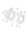
- FIG. 1 is an exploded view of an engine starter according to Embodiment 1 of the present invention.
- the engine starter in the first embodiment shown in FIG. 1 includes a motor driving force unit 10, a shaft 20, a pinion unit 30, a suction coil unit 40, a plunger 50, a lever 60, a bracket 70, a stopper 80, and a reduction gear unit 90. It is configured.
- the motor driving force unit 10 starts the engine.
- the shaft 20 is coupled to the output shaft side of the motor via a reduction gear unit 90.
- the pinion portion 30 is integrated with an overrunning clutch that is helically splined to the shaft 20 and can slide in the axial direction.
- the suction coil unit 40 sucks the plunger 50 by turning on the switch.
- the lever 60 transmits the movement of the plunger 50 by suction to the pinion unit 30.
- the bracket 70 fixes each component including the motor driving force portion 10, the shaft 20, and the pinion portion 30 to the engine side via a stopper 80 when the pinion moves.
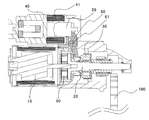
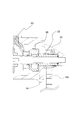
- FIG. 2 is a cross-sectional view when the engine starter according to Embodiment 1 of the present invention is attached to the engine.
- the switch When the engine is started, when the switch is turned on, the relay contact is closed, a current flows through the suction coil 41 of the suction coil unit 40, and the plunger 50 is sucked.
- the plunger 50 When the plunger 50 is sucked, the lever 60 is pulled and the lever 60 rotates around the lever rotation axis center 61.
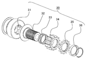
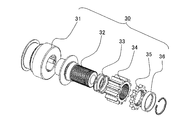
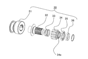
- FIG. 3 is an exploded view of components of the pinion unit 30 according to the first embodiment of the present invention.
- the pinion unit 30 includes an overrunning clutch 31, a shaft core 32, a coil spring 33, a second pinion gear 34, a first pinion gear 35, and a holding component 36.
- the pinion gear of the pinion unit 30 is divided into two parts, a second pinion gear 34 and a first pinion gear 35.
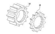
- the first pinion gear 35 has a tooth shape for synchronization at the tip, and is a gear for colliding with the ring gear 100, while the second pinion gear 34 is meshed. It is a gear that plays the role of transmitting rotational force later.
- the first pinion gear 35 is configured to have a smaller gear thickness and a smaller moment of inertia than the second pinion gear 34.
- the coil spring 33 is arranged coaxially with the shaft core 32 as shown in FIG.
- the overrunning clutch 31 is coupled to the shaft 20 by a helical spline.
- the shaft core 32 receives the transmission torque from the overrunning clutch 31 and transmits the rotational force to the first pinion gear 35 and the second pinion gear 34 through a groove carved in the shaft core 32.
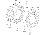
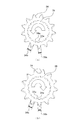
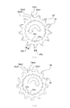
- FIG. 4 is a detailed perspective view of the first pinion gear 35 and the second pinion gear 34 according to the first embodiment of the present invention.
- a first pinion gear groove portion 35a and a second pinion gear groove portion 34a are dug as grooves that can move along the direction of the axis 20, respectively.
- the second pinion gear groove portion 34a is dug as a groove that meshes with the groove of the shaft core 32 with a minimum play.
- the first pinion gear groove portion 35a is dug larger in the width direction and depth direction of the groove than the second pinion gear groove portion 34a.
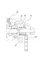
- FIG. 5 is a cross-sectional view of the starter portion at the moment when the first pinion gear 35 and the ring gear 100 collide according to Embodiment 1 of the present invention.
- the pushed pinion part 30 meshes with the ring gear 100 while the first pinion gear 35 of the two divided parts collides with the amount of meshing teeth shifted in the rotational direction.
- FIG. 6 is a diagram showing a positional relationship of the first pinion gear 35 and the second pinion gear 34 according to the first embodiment of the present invention as viewed from the front.
- FIG. 6A shows a state in which the first pinion gear 35 is slightly rotated counterclockwise with respect to the second pinion gear 34.
- FIG. 6B shows a state in which the first pinion gear 35 is slightly rotated to the right with respect to the second pinion gear 34.
- the positional relationship with the two-pinion gear 34 can be either the positional relationship shown in FIGS. 6A and 6B.
- the first pinion gear 35 is rotated by the amount of backlash by the frictional force of the contact portion with respect to the ring gear 100, and searches for the meshing phase.
- the first pinion gear 35 generates the axial force component of the pinion in addition to the processing surface (corresponding to the chamfered portion 35e) and the end surface (corresponding to the tooth surface facing the ring gear 100) of the tooth outer diameter edge portion. It has no surface to generate. That is, as a portion that comes into contact with the ring gear 100, surface contact by an end surface is fundamental, and chamfering is not performed except for the portion of the chamfered portion 35e.
- the first pinion gear 35 comes into contact with the ring gear 100 without being repelled by the impact force due to the rotational speed difference. That is, when the first pinion gear 35 and the ring gear 100 collide, even if the rotational speed difference is large, the pinion gear can be brought into contact without being repelled, there is no repelling meshing loss, and the rotational speed difference is further increased. Even when it is large, the meshing operation can be performed. Furthermore, the ring gear and the pinion gear can be synchronized by the tooth surface collision.
- the tooth thickness 35b of the first pinion gear 35 is smaller than the tooth thickness 34b of the second pinion gear 34. For this reason, the first pinion gear 35 has a large gap with the ring gear 100 and has a shape that can be easily inserted into the ring gear 100, so that the insertability can be improved. Furthermore, since it is possible to avoid applying a torque load when starting the engine with the first pinion gear 35, the first pinion gear 35 can be simplified in weight and size.
- the width of the tooth thickness 35b of the first pinion gear 35 that is rotated by the play of the first pinion gear groove 35a and the shaft core 32 does not exceed the region of the tooth thickness 34b of the second pinion gear 34. With such a tooth thickness, even after the first pinion gear 35 is engaged, the second pinion gear 34 can be smoothly inserted by the action of a chamfered portion 34c and the like described later.
- the first pinion gear 35 when the first pinion gear 35 comes into contact with the ring gear 100, the first pinion gear 35 is related to the phase relationship between the first pinion gear 35 and the ring gear 100. It is also conceivable that is not immediately inserted into the ring gear 100. However, even in such a case, the engine starter according to the first embodiment can perform more reliable synchronization and phase matching instantaneously. This point will be described next with reference to FIGS.
- FIG. 7 is a cross-sectional view of the starter portion in a state where the first pinion gear 35 and the ring gear 100 collide with each other and the first pinion gear 35 is inclined according to the first embodiment of the present invention.
- 8 is a cross-sectional view of the starter portion in a state where the ring gear 100 is inserted into the first pinion gear 35 and abuts against the second pinion gear 34 through the state of FIG. 7 according to the first embodiment of the present invention. is there.
- FIG. 9 shows the starter portion in which the ring gear 100 is inserted into the first pinion gear 35 and the second pinion gear 34 through the state of FIGS.
- FIG. 9 shows the starter portion in which the ring gear 100 is inserted into the first pinion gear 35 and the second pinion gear 34 through the state of FIGS.
- the first pinion gear groove portion 35a is dug larger in the width direction and depth direction of the groove than the second pinion gear groove portion 34a, and the first pinion gear groove portion. 35a has a backlash in the rotational direction and the radial direction with respect to the shaft core 32. Therefore, even if the first pinion gear 35 is not immediately inserted into the ring gear 100 due to the phase relationship, the groove diameter of the first pinion gear 35 has a backlash in the gear radial direction as well as in the gear rotation direction. Will be doing. Thus, the first pinion gear 35 can be tilted as shown in FIG. 7 by having backlash in the gear radial direction.
- a chamfered portion 35e having a corner R is provided on the tooth tip diameter portion of the first pinion gear 35 that contacts the ring gear 100 (see FIG. 4). Therefore, when the ring gear 100 rotates and enters a phase state in which the first pinion gear 35 can be inserted into the next tooth of the ring gear 100, the friction damper between the second pinion gear 34 and the shaft core 32. As a result, the first pinion gear 35 is inserted as shown in FIG. 8 in an operation in which the inclination is returned while being in contact with the ring gear 100.
- the first pinion gear 35 is in contact with the ring gear 100 due to the friction damper effect of the second pinion gear 34 by providing the groove diameter of the first pinion gear 35 with backlash in the gear radial direction as well as in the gear rotation direction. 35 can perform an operation of searching for a gap in the ring gear 100 and can increase a range in which the first pinion gear 35 can be inserted relative to the gap in the ring gear 100.
- the first pinion gear 35 is inserted into the adjacent tooth of the ring gear 100 by the operation of returning the inclination without being repelled by the ring gear 100, and the rotation can be synchronized by the contact between the tooth surfaces.
- the collision surface when inserted is the tooth surface 35d of the first pinion gear 35 and the ring gear 100, and even when there is a difference in the rotational speed, the collision occurs in the rotational direction, and the rotation is synchronized with the torque.
- the clutch is idled by the overrunning clutch 31 when synchronized by applying the tooth surface of the first pinion gear 35, so that the impact is applied to the first pinion gear 35. Because it is only a mass, the impact is small and the noise is small.
- the pinion portion 30 thus synchronized shifts to a state in which the ring gear 100 and the second pinion gear 34 collide as shown in FIG. 8 by further pressing.
- the chamfered portion 34c shown in FIG. 4 is provided on both sides of the tooth surface edge portion of the second pinion gear 34 on the first pinion gear 35 side. Therefore, the second pinion gear 34 and the ring gear 100 are engaged with each other as shown in FIG.
- the chamfered portion 34c has a component that rebounds in the axial direction, but there is no problem because the pinion portion 30 and the ring gear 100 are synchronized by the first pinion gear 35.
- the ring gear 100 can be smoothly inserted into the second pinion gear 34 regardless of the relative rotation direction of the pinion gear and the ring gear 100.
- the first pinion gear 35 meshes with the ring gear 100 and is synchronized with the second pinion gear 34 meshing with the ring gear 100 to start the engine. Can be made. Then, after the second pinion gear 34 and the ring gear 100 are engaged, torque transmission between the pinion portion 30 and the ring gear 100 is performed only between the tooth surface 34d of the second pinion gear and the ring gear 100. As a result, transmission loss can be suppressed by appropriately designing the second pinion gear 34.
- the gear rattling noise that causes the cranking sound when the engine is started is determined by the gear relationship between the second pinion gear 34 and the ring gear 100. For this reason, there is no problem even if the first pinion gear 35 is a tooth having a small tooth thickness and a large backlash. That is, the specification of the teeth of the first pinion gear 35 increases the backlash with the ring gear 100 by changing the displacement, the tip outer diameter, or the pressure angle with respect to the specification of the teeth of the second pinion gear 34. There is no problem.
- the first pinion gear having the synchronization tooth shape as described above is rotated after meshing with the first pinion gear.
- the pinion gear having a structure divided into two parts for the second pinion gear that plays a role of transmitting force it is possible to engage with each other instantly by the operation of one tooth.
- the insertability between the ring gear and the pinion portion can be improved, the tooth shape can be extended due to wear of the end face, and noise and transmission loss can be suppressed.
- the first pinion gear is not limited to, for example, a tooth shape as shown in FIG.
- FIG. 10 is a perspective view in which the first pinion gear according to the first embodiment of the present invention is configured with protrusions. As shown in FIG. 10, there is no problem even if the shape of the wave is the same as the number of teeth.
- the mechanism for pushing out the pinion part the case where the pinion part is pushed out by transmitting the pulling force by the plunger to the lever has been described.
- the mechanism is not limited to such a mechanism.
- other power sources such as using motor torque may be used.
- Embodiment 2 the structure of the pinion part that can further suppress wear by decentering the backlash between the first pinion gear 35 and the second pinion gear 34 in the phase will be described.
- the configuration of the engine starting device in the second embodiment is the same as that in FIG. 1 in the first embodiment, and the motor driving force unit 10, the shaft 20, the pinion unit 30, the suction coil unit 40, the plunger 50, and the lever 60.
- the bracket 70, the stopper 80, and the reduction gear unit 90 are configured such that the pinion unit 30 is pushed out while rotating.
- FIG. 11 is an exploded view of the components of the pinion unit 30 according to the second embodiment of the present invention.
- the pinion unit 30 includes an overrunning clutch 31, a shaft core 32, a coil spring 33, a second pinion gear 34, a first pinion gear 35, and a holding component 36.
- the component configuration and role of the pinion gear of the pinion unit 30 are the same as those in the first embodiment, and a detailed description thereof will be omitted.
- FIG. 12 is a detailed perspective view of the first pinion gear 35 and the second pinion gear 34 according to the second embodiment of the present invention.
- a first pinion gear groove portion 35a and a second pinion gear groove portion 34a are dug as grooves that can move along the direction of the axis 20, respectively.
- the second pinion gear groove portion 34a is dug as a groove that meshes with the groove of the shaft core 32 with a minimum play.
- the first pinion gear groove portion 35a is dug larger in the width direction and depth direction of the groove than the second pinion gear groove portion 34a.
- FIG. 13 is a diagram illustrating a positional relationship of the first pinion gear and the second pinion gear according to Embodiment 2 of the present invention as viewed from the front.
- the pinion is eccentric in the surface direction (corresponding to the left rotation direction and the right rotation direction in FIG. 13) in which torque is transmitted to the ring gear 100 by the rotation of the motor. That is, in the first embodiment, as shown in FIG. 6, the amount of the tooth thickness of the second pinion gear 34 protruding from the tooth thickness of the first pinion gear 35 is as shown in FIG. In both cases of 6 (b), the thickness was equivalent. On the other hand, in the second embodiment, the amount of protrusion shown in FIG. 13 (a) is different from the amount of protrusion shown in FIG. 13 (b). "
- FIG. 13A shows a state in which the first pinion gear 35 is displaced in the direction of the arrow due to the pinion rotating in the direction of torque transmission. While torque is being transmitted, the first pinion gear 35 cannot transmit torque on the transmission surface side of the pinion gear because the surface 35d1 of the first pinion gear is more concave than the second pinion gear surface 34d1. Become.
- FIG. 13B shows a state where the rotation speed of the ring gear 100 is fast and the play of the first pinion gear 35 is shifted in the direction of the arrow.
- This state is a state that occurs only when the second pinion gear 34 is not engaged with the ring gear 100 and only the first pinion gear 35 is engaged.
- the state until the first pinion gear 35 meshes with and synchronizes with the ring gear 100 is the same as that of the first embodiment. In this state, the influence of the meshing property due to the eccentricity is irrelevant.
- the pinion gear meshed with and synchronized with the first pinion gear 35 is brought into the state shown in FIG. 8 in the first embodiment by further pressing, and shifts to a state in which the ring gear 100 and the second pinion gear 34 collide. . That is, it is conceivable that the second pinion gear 34 collides with the ring gear 100 in the state as shown in FIG.
- two chamfers of a motor torque transmission surface side chamfer 34c1 and a motor torque non-transmission surface side chamfer 34c2 are applied to the tooth surface edge portion of the second pinion gear 34 on the first pinion gear 35 side. (See FIG. 12).
- the step to the torque transmission surface side of the second pinion gear 34 is small due to the eccentricity, and the ring gear 100 On the other hand, the second pinion gear 34 is easy to enter.
- the chamfer 34c2 on the opposite side to the tooth chamfer 34c1 on the torque transmission surface side by the pinion is different. Further, the size is determined by an area hidden by the backlash of the first pinion gear 35.
- the ring gear 100 is synchronized with the first pinion gear 35 at the moment of contact with the second pinion gear 34, and is in a state where the phase is different. Therefore, by setting the chamfer 34c1 on the torque transmission surface side of the second pinion gear 34 to be an involute chamfer, it is possible to make the chamfer along the rotation of the pinion and to further suppress wear.
- the backlash between the first pinion gear and the second pinion gear is provided so as to be eccentric in phase.
- the phase alignment between the second pinion gear and the first pinion gear is pushed in, the second pinion gear is pushed in smoothly, and problems such as wear are eliminated. Therefore, in the meshing between the ring gear and each of the first pinion gear and the second pinion gear, it is possible to mesh smoothly even when there is a rotational speed difference. As a result, not only can control restrictions be relaxed, restartability can be reduced, noise can be reduced, but wear can be minimized.
- Embodiment 3 In the third embodiment, with respect to the axial movement mechanism of the first pinion gear 35 and the second pinion gear 34, the frictional force of the first pinion gear 35 is provided separately from the shaft core, thereby increasing the damper effect. A structure that can be performed will be described.
- the configuration of the engine starting device in the third embodiment is the same as that in FIG. 1 in the first embodiment, and the motor driving force unit 10, the shaft 20, the pinion unit 30, the suction coil unit 40, the plunger 50, and the lever 60.
- the bracket 70, the stopper 80, and the reduction gear unit 90 are configured such that the pinion unit 30 is pushed out while rotating.
- FIG. 14 is an exploded view of components of the pinion unit 30 according to the third embodiment of the present invention.
- the pinion unit 30 includes an overrunning clutch 31, a shaft core 32, a coil spring 33, a second pinion gear 34, a first pinion gear 35, and a holding component 36.
- the basic component configuration and role of the pinion unit 30 are the same as those in the first embodiment, and a detailed description thereof will be omitted.
- the second pinion gear 34 has a protrusion (hereinafter referred to as a groove protrusion 34e) in which a groove is carved between the groove of the shaft core 32 and the tooth surface of the second pinion 34 in the direction of the first pinion gear 35.
- the first pinion gear 35 is a groove carved in the groove protrusion 34e and meshes with the groove portion 35a of the first pinion gear.
- the groove portion 35a of the first pinion gear and the groove portion 34a of the second pinion gear mesh with separate grooves. Therefore, since the groove portion 35a of the first pinion gear is a groove that does not transmit torque, the number of grooves can be set by reducing the number of teeth, and the meshing shape of the groove protrusion 34e of the second pinion gear is It can be created in a shape that does not depend on the groove shape of the core 32.
- the frictional force of the first pinion gear can be provided separately from the shaft core with respect to the axial movement mechanism of the first pinion gear and the second pinion gear. That is, the first pinion gear can be configured to move in the axial direction independently of the pinion portion. As a result, only the portion of the first pinion gear 35 can be enlarged with respect to the damper function by the frictional force that moves in the axial direction by the spring.
- Embodiment 4 FIG.
- the structure that increases the damper effect has been described with respect to the axial movement mechanism of the first pinion gear 35 and the second pinion gear 34.
- the fourth embodiment when the friction coefficient between the pinion gears 34 and 35 and the ring gear 100 is small with respect to the operation mechanism in the rotational direction of the first pinion gear 35 and the second pinion gear 34, A structure in which the frictional force in the rotational direction of the first pinion gear 35 and the ring gear 100 can be made larger than the frictional force in the rotational direction of the first pinion gear 35 and the second pinion gear 34 will be described.
- the configuration of the engine starting device in the fourth embodiment is the same as that in FIG. 1 in the first embodiment, and the motor driving force unit 10, the shaft 20, the pinion unit 30, the suction coil unit 40, the plunger 50, and the lever 60.
- the bracket 70, the stopper 80, and the reduction gear unit 90 are configured such that the pinion unit 30 is pushed out while rotating.
- FIG. 15 is an exploded view of the components of the pinion unit 30 according to the fourth embodiment of the present invention.
- the pinion unit 30 includes an overrunning clutch 31, a shaft core 32, a coil spring 33, a coil spring 33 b, a second pinion gear 34, a first pinion gear 35, and a holding component 36.
- the basic component configuration and role of the pinion unit 30 are the same as those in the first embodiment, and a detailed description thereof will be omitted.
- the fourth embodiment of the present invention is different in that the coil spring is divided into two (coil springs 33, 33b). Therefore, this difference will be mainly described below.
- FIG. 16 is a cross-sectional view of the starter portion before the first pinion gear 35 and the ring gear 100 collide according to the fourth embodiment of the present invention.
- a coil spring 33 b exists between the first pinion gear 35 and the second pinion gear 34 separately from the coil spring 33 that pushes the second pinion gear 34 in the direction in which the shaft is pushed.
- FIG. 17 is a cross-sectional view of the starter portion in a state where the first pinion gear 35 and the ring gear 100 collide with each other and the first pinion gear 35 is inclined according to the fourth embodiment of the present invention.
- the first pinion gear is separated from the coil spring that pushes the second pinion gear in the pushing direction of the shaft.
- a coil spring is also provided between the pinion gear and the second pinion gear, and the structure of the coil spring divided into two is provided.
Landscapes
- Engineering & Computer Science (AREA)
- Chemical & Material Sciences (AREA)
- Combustion & Propulsion (AREA)
- Mechanical Engineering (AREA)
- General Engineering & Computer Science (AREA)
- Gears, Cams (AREA)
Priority Applications (3)
| Application Number | Priority Date | Filing Date | Title |
|---|---|---|---|
| EP11818036.3A EP2650529B1 (en) | 2010-08-20 | 2011-07-27 | Engine |
| US13/877,303 US9249770B2 (en) | 2010-08-20 | 2011-07-27 | Engine starter |
| CN201180050601.8A CN103168166B (zh) | 2010-08-20 | 2011-07-27 | 发动机启动装置 |
Applications Claiming Priority (6)
| Application Number | Priority Date | Filing Date | Title |
|---|---|---|---|
| JP2010184702 | 2010-08-20 | ||
| JP2010-184702 | 2010-08-20 | ||
| JP2010266253 | 2010-11-30 | ||
| JP2010-266253 | 2010-11-30 | ||
| JP2011072078A JP5804742B2 (ja) | 2010-08-20 | 2011-03-29 | エンジン始動装置 |
| JP2011-072078 | 2011-03-29 |
Publications (1)
| Publication Number | Publication Date |
|---|---|
| WO2012023393A1 true WO2012023393A1 (ja) | 2012-02-23 |
Family
ID=45605054
Family Applications (1)
| Application Number | Title | Priority Date | Filing Date |
|---|---|---|---|
| PCT/JP2011/067121 Ceased WO2012023393A1 (ja) | 2010-08-20 | 2011-07-27 | エンジン始動装置 |
Country Status (5)
| Country | Link |
|---|---|
| US (1) | US9249770B2 (enExample) |
| EP (1) | EP2650529B1 (enExample) |
| JP (1) | JP5804742B2 (enExample) |
| CN (1) | CN103168166B (enExample) |
| WO (1) | WO2012023393A1 (enExample) |
Cited By (1)
| Publication number | Priority date | Publication date | Assignee | Title |
|---|---|---|---|---|
| JP2015232314A (ja) * | 2014-05-16 | 2015-12-24 | 三菱電機株式会社 | エンジン始動装置 |
Families Citing this family (7)
| Publication number | Priority date | Publication date | Assignee | Title |
|---|---|---|---|---|
| US9512812B2 (en) | 2011-03-31 | 2016-12-06 | Mitsubishi Electric Corporation | Engine starting device |
| KR101488128B1 (ko) * | 2011-03-31 | 2015-01-29 | 미쓰비시덴키 가부시키가이샤 | 엔진 시동 장치 |
| JP6292771B2 (ja) * | 2013-06-03 | 2018-03-14 | 三菱電機株式会社 | アイドルストップシステムを採用した車両のエンジン始動装置 |
| CN106523236A (zh) * | 2015-09-15 | 2017-03-22 | 上海法雷奥汽车电器系统有限公司 | 用于起动机的驱动齿轮 |
| FR3048734B1 (fr) * | 2016-03-09 | 2019-07-05 | Valeo Equipements Electriques Moteur | Pignon de demarreur de vehicule automobile a performances acoustiques ameliorees |
| FR3051849A1 (fr) * | 2016-05-25 | 2017-12-01 | Valeo Equip Electr Moteur | Demarreur muni d'un pignon ayant au moins une dent profilee |
| DE102020117737A1 (de) * | 2020-07-06 | 2022-01-13 | Seg Automotive Germany Gmbh | Ritzel für Startermotor, Zahnkranz für Startermotor und Startermotor mit einem solchen Ritzel und/oder einem solchen Zahnkranz |
Citations (6)
| Publication number | Priority date | Publication date | Assignee | Title |
|---|---|---|---|---|
| JP2000274336A (ja) * | 1999-03-25 | 2000-10-03 | Mitsubishi Motors Corp | 内燃機関の始動装置 |
| JP2002070699A (ja) | 2000-08-23 | 2002-03-08 | Toyota Motor Corp | 燃料消費節約型自動車 |
| JP2002303236A (ja) * | 2001-04-02 | 2002-10-18 | Denso Corp | スタータ |
| JP2006132343A (ja) | 2004-11-02 | 2006-05-25 | Toyota Motor Corp | 内燃機関の始動装置及びその始動装置に備えられたスタータギアユニット |
| JP2009168230A (ja) | 2008-01-21 | 2009-07-30 | Denso Corp | ピニオンおよびそれを用いたスタータ |
| JP2009245665A (ja) * | 2008-03-28 | 2009-10-22 | Equos Research Co Ltd | 燃料電池システム及び車両 |
Family Cites Families (12)
| Publication number | Priority date | Publication date | Assignee | Title |
|---|---|---|---|---|
| US2847857A (en) * | 1958-08-19 | Engine starter gearing | ||
| US1847726A (en) * | 1928-06-29 | 1932-03-01 | Delco Remy Corp | Engine starting apparatus |
| US2500132A (en) * | 1948-08-09 | 1950-03-07 | Bendix Aviat Corp | Heavy-duty engine starter gearing |
| US2841988A (en) * | 1956-02-13 | 1958-07-08 | Bendix Aviat Corp | Starter gearing for internal combustion engines |
| US3084561A (en) * | 1960-05-19 | 1963-04-09 | Electric Auto Lite Co | Coaxial solenoid for starter motors |
| JPS56173766U (enExample) * | 1980-05-27 | 1981-12-22 | ||
| JP2003328912A (ja) * | 2002-05-10 | 2003-11-19 | Mitsubishi Electric Corp | スタータ |
| US6948392B2 (en) * | 2003-03-07 | 2005-09-27 | Tech Development, Inc. | Inertia drive torque transmission level control and engine starter incorporating same |
| DE102006011644A1 (de) * | 2006-03-06 | 2007-09-13 | Robert Bosch Gmbh | Vorrichtung mit einem ersten Getriebeteil zum Einspuren in ein zweites Getriebeteil, insbesondere Startvorrichtung mit einem Ritzel zum Einspuren in einen Zahnkranz einer Brennkraftmaschine sowie Verfahren zum Betrieb einer derartigen Vorrichtung |
| JP2009024665A (ja) * | 2007-07-23 | 2009-02-05 | Toyota Central R&D Labs Inc | エンジン始動装置 |
| DE102008054965B4 (de) * | 2008-12-19 | 2018-08-23 | Seg Automotive Germany Gmbh | Verfahren und Vorrichtung für Start-Stopp-Anlagen von Brennkraftmaschinen in Kraftfahrzeugen |
| KR101488128B1 (ko) * | 2011-03-31 | 2015-01-29 | 미쓰비시덴키 가부시키가이샤 | 엔진 시동 장치 |
-
2011
- 2011-03-29 JP JP2011072078A patent/JP5804742B2/ja not_active Expired - Fee Related
- 2011-07-27 CN CN201180050601.8A patent/CN103168166B/zh not_active Expired - Fee Related
- 2011-07-27 WO PCT/JP2011/067121 patent/WO2012023393A1/ja not_active Ceased
- 2011-07-27 US US13/877,303 patent/US9249770B2/en not_active Expired - Fee Related
- 2011-07-27 EP EP11818036.3A patent/EP2650529B1/en active Active
Patent Citations (6)
| Publication number | Priority date | Publication date | Assignee | Title |
|---|---|---|---|---|
| JP2000274336A (ja) * | 1999-03-25 | 2000-10-03 | Mitsubishi Motors Corp | 内燃機関の始動装置 |
| JP2002070699A (ja) | 2000-08-23 | 2002-03-08 | Toyota Motor Corp | 燃料消費節約型自動車 |
| JP2002303236A (ja) * | 2001-04-02 | 2002-10-18 | Denso Corp | スタータ |
| JP2006132343A (ja) | 2004-11-02 | 2006-05-25 | Toyota Motor Corp | 内燃機関の始動装置及びその始動装置に備えられたスタータギアユニット |
| JP2009168230A (ja) | 2008-01-21 | 2009-07-30 | Denso Corp | ピニオンおよびそれを用いたスタータ |
| JP2009245665A (ja) * | 2008-03-28 | 2009-10-22 | Equos Research Co Ltd | 燃料電池システム及び車両 |
Cited By (1)
| Publication number | Priority date | Publication date | Assignee | Title |
|---|---|---|---|---|
| JP2015232314A (ja) * | 2014-05-16 | 2015-12-24 | 三菱電機株式会社 | エンジン始動装置 |
Also Published As
| Publication number | Publication date |
|---|---|
| EP2650529A1 (en) | 2013-10-16 |
| US20130233128A1 (en) | 2013-09-12 |
| CN103168166B (zh) | 2015-08-12 |
| US9249770B2 (en) | 2016-02-02 |
| JP2012132426A (ja) | 2012-07-12 |
| JP5804742B2 (ja) | 2015-11-04 |
| EP2650529B1 (en) | 2020-03-11 |
| EP2650529A4 (en) | 2017-12-06 |
| CN103168166A (zh) | 2013-06-19 |
Similar Documents
| Publication | Publication Date | Title |
|---|---|---|
| JP5804742B2 (ja) | エンジン始動装置 | |
| JPWO2012077501A1 (ja) | エンジン始動装置 | |
| JP5762371B2 (ja) | エンジン始動装置 | |
| CN102317615B (zh) | 用于机动车辆中的内燃机的起停系统的方法和装置 | |
| JP5444503B2 (ja) | エンジン始動装置 | |
| CN103459828B (zh) | 发动机启动装置 | |
| JP6012788B2 (ja) | エンジン始動装置 | |
| JP5632679B2 (ja) | 同期装置およびそれを備える変速機 | |
| JP2012041881A (ja) | エンジン始動装置 | |
| JP5957071B2 (ja) | スタータ | |
| JP5955362B2 (ja) | エンジン始動装置 | |
| JP2014224489A (ja) | エンジン始動装置 | |
| WO2011138905A1 (ja) | エンジン始動装置 | |
| JP2014224489A5 (enExample) |
Legal Events
| Date | Code | Title | Description |
|---|---|---|---|
| 121 | Ep: the epo has been informed by wipo that ep was designated in this application |
Ref document number: 11818036 Country of ref document: EP Kind code of ref document: A1 |
|
| NENP | Non-entry into the national phase |
Ref country code: DE |
|
| WWE | Wipo information: entry into national phase |
Ref document number: 13877303 Country of ref document: US |
|
| WWE | Wipo information: entry into national phase |
Ref document number: 2011818036 Country of ref document: EP |
|
| NENP | Non-entry into the national phase |
Ref country code: JP |