WO2012023378A1 - 電線、コイル、電線の設計装置及び電気モータ - Google Patents
電線、コイル、電線の設計装置及び電気モータ Download PDFInfo
- Publication number
- WO2012023378A1 WO2012023378A1 PCT/JP2011/066563 JP2011066563W WO2012023378A1 WO 2012023378 A1 WO2012023378 A1 WO 2012023378A1 JP 2011066563 W JP2011066563 W JP 2011066563W WO 2012023378 A1 WO2012023378 A1 WO 2012023378A1
- Authority
- WO
- WIPO (PCT)
- Prior art keywords
- wire
- resistance
- frequency
- electric wire
- copper
- Prior art date
- Legal status (The legal status is an assumption and is not a legal conclusion. Google has not performed a legal analysis and makes no representation as to the accuracy of the status listed.)
- Ceased
Links
Images


Classifications
-
- H—ELECTRICITY
- H02—GENERATION; CONVERSION OR DISTRIBUTION OF ELECTRIC POWER
- H02K—DYNAMO-ELECTRIC MACHINES
- H02K3/00—Details of windings
-
- G—PHYSICS
- G06—COMPUTING OR CALCULATING; COUNTING
- G06F—ELECTRIC DIGITAL DATA PROCESSING
- G06F30/00—Computer-aided design [CAD]
-
- H—ELECTRICITY
- H01—ELECTRIC ELEMENTS
- H01B—CABLES; CONDUCTORS; INSULATORS; SELECTION OF MATERIALS FOR THEIR CONDUCTIVE, INSULATING OR DIELECTRIC PROPERTIES
- H01B1/00—Conductors or conductive bodies characterised by the conductive materials; Selection of materials as conductors
- H01B1/02—Conductors or conductive bodies characterised by the conductive materials; Selection of materials as conductors mainly consisting of metals or alloys
- H01B1/023—Alloys based on aluminium
-
- H—ELECTRICITY
- H01—ELECTRIC ELEMENTS
- H01B—CABLES; CONDUCTORS; INSULATORS; SELECTION OF MATERIALS FOR THEIR CONDUCTIVE, INSULATING OR DIELECTRIC PROPERTIES
- H01B1/00—Conductors or conductive bodies characterised by the conductive materials; Selection of materials as conductors
- H01B1/02—Conductors or conductive bodies characterised by the conductive materials; Selection of materials as conductors mainly consisting of metals or alloys
- H01B1/026—Alloys based on copper
-
- H—ELECTRICITY
- H02—GENERATION; CONVERSION OR DISTRIBUTION OF ELECTRIC POWER
- H02K—DYNAMO-ELECTRIC MACHINES
- H02K3/00—Details of windings
- H02K3/02—Windings characterised by the conductor material
-
- H—ELECTRICITY
- H02—GENERATION; CONVERSION OR DISTRIBUTION OF ELECTRIC POWER
- H02K—DYNAMO-ELECTRIC MACHINES
- H02K3/00—Details of windings
- H02K3/04—Windings characterised by the conductor shape, form or construction, e.g. with bar conductors
-
- H—ELECTRICITY
- H01—ELECTRIC ELEMENTS
- H01B—CABLES; CONDUCTORS; INSULATORS; SELECTION OF MATERIALS FOR THEIR CONDUCTIVE, INSULATING OR DIELECTRIC PROPERTIES
- H01B7/00—Insulated conductors or cables characterised by their form
- H01B7/30—Insulated conductors or cables characterised by their form with arrangements for reducing conductor losses when carrying alternating current, e.g. due to skin effect
-
- H—ELECTRICITY
- H01—ELECTRIC ELEMENTS
- H01F—MAGNETS; INDUCTANCES; TRANSFORMERS; SELECTION OF MATERIALS FOR THEIR MAGNETIC PROPERTIES
- H01F5/00—Coils
-
- Y—GENERAL TAGGING OF NEW TECHNOLOGICAL DEVELOPMENTS; GENERAL TAGGING OF CROSS-SECTIONAL TECHNOLOGIES SPANNING OVER SEVERAL SECTIONS OF THE IPC; TECHNICAL SUBJECTS COVERED BY FORMER USPC CROSS-REFERENCE ART COLLECTIONS [XRACs] AND DIGESTS
- Y02—TECHNOLOGIES OR APPLICATIONS FOR MITIGATION OR ADAPTATION AGAINST CLIMATE CHANGE
- Y02T—CLIMATE CHANGE MITIGATION TECHNOLOGIES RELATED TO TRANSPORTATION
- Y02T10/00—Road transport of goods or passengers
- Y02T10/80—Technologies aiming to reduce greenhouse gasses emissions common to all road transportation technologies
- Y02T10/82—Elements for improving aerodynamics
Definitions
- the present invention relates to an electric wire, a coil, an electric wire design device, and an electric motor.
- CCA wire copper-coated aluminum wire
- Al wire aluminum wire
- Cu wires copper-coated copper wire
- JP 2009-129550 A Japanese Unexamined Patent Publication No. Sho 62-76216 JP 2005-108654 A International Publication No. 2006/046358 JP 2002-150633 A
- an object of the present invention is to provide an electric wire, coil, and electric wire design device that can reduce or reduce an AC resistance by making loss due to an eddy current equal to or smaller than a reference Cu wire. And providing an electric motor.
- an electric wire including a conductor portion made of a material having a higher volume resistivity than copper, and in the frequency band in which the electric wire is used, the conductor portion with respect to an AC resistance of a reference Cu wire
- An electric wire is provided in which the volume resistivity of the conductor is defined so that the ratio of the AC resistance is less than 1.
- the reference Cu wire may have the same wire diameter as the conductor portion.
- the AC resistance of the electric wire and the AC resistance of the Cu wire as a reference match each other, and the AC resistance of the electric wire between each other is smaller than the AC resistance of the Cu wire as a reference.
- a direct current resistance value per length may be defined.
- the DC resistance value is defined as Rdc as the DC resistance value and f2 as the second frequency.
- Rdc the DC resistance value
- f2 the second frequency.
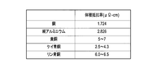
- the conductor portion may be made of any one of brass, phosphor bronze, silica bronze, a copper alloy selected from a copper / beryllium alloy and a copper / nickel / silicon alloy, and copper-coated aluminum.
- the frequency band in which the electric wire is used may include harmonic frequencies from the reference frequency to the 20th order.
- the frequency band in which the electric wire is used may be 10 kHz to 1 MHz.
- a coil using an electric wire as a strand includes a conductor portion made of a material having a higher volume resistivity than copper, and in a frequency band in which the electric wire is used, a reference A coil is provided in which the volume resistivity of the conductor is defined such that the ratio of the AC resistance of the conductor to the AC resistance of the Cu wire is less than 1.
- the reference Cu wire may have the same wire diameter as the conductor portion.
- the AC resistance of the electric wire and the AC resistance of the Cu wire used as a reference coincide with each other, and the AC resistance of the electric wire between them is smaller than the AC resistance of the Cu wire used as a reference.
- the volume resistivity of the conductor portion is divided by the cross-sectional area so that the second frequency is equal to or higher than the upper limit value of the frequency band in which the electric wire is used among the first frequency and the second frequency larger than the first frequency.
- a DC resistance value per unit length may be defined.
- the DC resistance value is defined as Rdc as the DC resistance value and f2 as the second frequency.
- Rdc the DC resistance value
- f2 the second frequency.
- the conductor portion may be composed of any one of brass, phosphor bronze, quartz bronze, a copper alloy selected from a copper / beryllium alloy and a copper / nickel / silicon alloy, and copper-coated aluminum. .
- the frequency band in which the wire is used may include harmonic frequencies from the reference frequency to the 20th order.
- the frequency band in which the electric wire is used may be 10 kHz to 1 MHz.
- an electric wire design device made of a material having a volume resistivity higher than that of copper, the AC resistance of a conductor part that is a candidate for an electric wire in a frequency band in which the electric wire is used, and A ratio calculator for calculating the AC resistance of the reference Cu wire, a ratio calculator for calculating the ratio of the AC resistance due to the proximity effect of the conductor to the AC resistance due to the proximity effect of the reference Cu wire, and a ratio of 1
- an electric wire design apparatus provided with the determination part which determines that a candidate is applicable to an electric wire is provided.
- a plurality of iron cores arranged in a circular shape, a central conductor made of Al wire or aluminum or an aluminum alloy, and a coating layer made of copper covering the central conductor are provided.
- the coil includes a plurality of coils wound around a plurality of iron cores, and a rotor that rotates by applying an alternating current to the plurality of coils, and the AC resistance of the coil is an alternating current of a coil wound with a reference Cu wire.
- An electric motor is provided in which the frequency of an alternating current applied to a coil is controlled by an inverter method so as to fall between a first frequency that is smaller than a resistance and a second frequency that is higher than the first frequency.
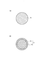
- FIG.1 (a) is sectional drawing which shows an example of the electric wire which concerns on the 1st Embodiment of this invention.
- FIG.1 (b) is sectional drawing which shows another example of the electric wire which concerns on the 1st Embodiment of this invention.
- It is a schematic diagram for demonstrating the skin effect which concerns on the 1st Embodiment of this invention.
- It is sectional drawing of the conducting wire of 2 layer structure. It is the schematic which shows the electromagnetic field of the conducting wire surface where the electric current is flowing.
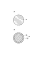
- FIG. 58A is a cross-sectional view showing an example of an electric wire according to the third embodiment of the present invention.
- FIG. 58B is a cross-sectional view showing another example of the electric wire according to the third embodiment of the present invention.
- the electric wire according to the first embodiment of the present invention is an electric wire used in a specific frequency band and is made of a material having a higher volume resistivity than copper. 11.
- the ratio of the AC resistance due to the proximity effect of the conductor portion 11 to the AC resistance due to the proximity effect of the Cu wire as a reference in a specific frequency band is less than 1.
- the volume resistivity of the conductor portion 11 is defined.
- specific frequency band means a frequency band defined (set) as a range in which the electric wire (product) is used.
- the upper limit value, lower limit value, and range of the “specific frequency band” are appropriately set according to the specifications of each product, and are not particularly limited.
- the “specific frequency band” may be, for example, about several kHz to 100 kHz, or about 10 kHz to 1 MHz. In the case of an IH cooker, it may be about 20 kHz to 60 kHz. As long as the product uses the commercial power frequency of Japan, the United States, and Europe as it is, it may be about 50 kHz to 60 kHz.
- the “reference Cu wire” is defined (set) in advance, and may have the same or different wire diameter as the conductor portion 11.
- the diameter of the conductor 11 is preferably about 0.05 mm to 0.6 mm, but is not particularly limited.
- copper alloys such as brass, phosphor bronze, quartz bronze, copper / beryllium alloy, and copper / nickel / silicon alloy
- Brass is an alloy (Cu—Zn) containing copper (Cu) and zinc (Zn), and may contain a small amount of elements other than copper and zinc.
- Silica bronze is an alloy (Cu—Sn—Si) containing copper, tin (Sn) and silicon (Si), and may contain a small amount of elements other than copper, tin and silicon.
- Phosphor bronze is an alloy (Cu—Sn—P) containing copper, tin and phosphorus (P), and may contain a small amount of elements other than copper, tin and phosphorus.
- These copper alloy wires are, for example, one-principle annealed and may be plated with tin, copper, chromium (Cr), or the like.
- the conductor part 11 may have various shapes, such as flat shape other than cylindrical shape.
- the electric wire according to the first embodiment of the present invention includes a central conductor 12 made of aluminum (Al) or an aluminum alloy, and copper (Cu) covering the central conductor 12.
- the CCA line provided with the coating layer 13 made of may be used as the conductor portion 11.
- the diameter of the entire CCA line is preferably about 0.05 mm to 0.6 mm.
- the cross-sectional area of the covering layer 13 is 15% or less with respect to the cross-sectional area of the entire electric wire including the central conductor 12 and the covering layer 13, preferably about 3% to 15%, more preferably about 3% to 10%. More desirably, it is about 3% to 5%.
- the AC resistance can be reduced as the ratio of the cross-sectional area of the covering layer 13 to the entire electric wire is smaller.
- the center conductor 12 for example, an aluminum alloy of electrical aluminum (EC aluminum) or an Al—Mg—Si based alloy (JIS 6000 series) can be used.
- the aluminum alloy has a larger volume resistivity than EC aluminum. Therefore it is more desirable.
- the winding of a transformer, a reactor, or the like is an insulating coating of Cu wire with polyurethane, polyester, polyesterimide, polyamideimide, polyimide, or the like.
- the coaxial cable is a high-frequency current signal, for example, a CCA line is used in consideration of the skin effect characteristics.
- the AC resistance R ac is expressed by the following equation (1), where the DC resistance component is R dc , the AC resistance due to the skin effect is R s , and the AC resistance due to the proximity effect (proximity effect component) is R p .
- k s represents the skin effect coefficient
- each electromagnetic field uses a complex expression, and the time factor is ej ⁇ t .
- ⁇ represents an angular frequency.
- the electric current generates a z-direction component E z of the electric field, which satisfies the following wave equation (2).
- ⁇ 0 represents the magnetic permeability in vacuum.
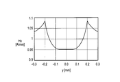
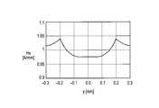
- the magnetic field H ⁇ has only a ⁇ direction component and is given as follows.
- J ⁇ (z) represents the first kind Bessel function
- the power flow flowing into the conducting wire shown in FIG. 6 is calculated by the following equation (15) from the Poynting vector.
- Equation (18) becomes
- the magnetic potential satisfies the following wave equation (25).
- ⁇ 0 represents the magnetic permeability in vacuum.
- Equation (25) The solution of equation (25) can be set as follows.
- the magnetic field H ⁇ is obtained as follows.
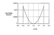
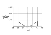
- the loss P L of the conducting wire is obtained as follows.
- Equation (43) becomes the following Equation (46).
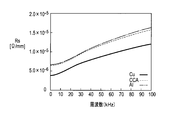
- the proximity effect when the external magnetic field intensity H of the brass wire, phosphor bronze wire, quartz bronze wire and Cu wire according to the comparative example according to the first embodiment of the present invention is 1 (A / mm).
- FIG. 9 shows that the AC resistance of the brass wire, phosphor bronze wire, and silicon bronze wire is smaller than the AC resistance of the Cu wire in a predetermined frequency band.
- the AC resistance when the external magnetic field strength H of the brass wire having a wire diameter of 0.4 mm and the Cu wire as a comparative example is 1 A / mm is expressed by the above-described equations (1), (18) and (48).
- the brass wire has a smaller AC resistance than the Cu wire having the same wire diameter in the frequency band defined between the first frequency f1 and the second frequency f2. That is, on the lower frequency side than the first frequency f1, the AC resistance of the brass wire is larger than the AC resistance of the Cu wire.
- the AC resistance of the brass wire matches the AC resistance of the Cu wire, and eddy current loss becomes dominant on the higher frequency side than the first frequency f1, so the AC resistance of the brass wire and Cu
- the magnitude of the AC resistance of the line is reversed.
- the AC resistance of the Cu wire is larger than the AC resistance of the brass wire.
- the AC resistance of the brass wire again coincides with the AC resistance of the Cu wire, and on the higher frequency side than the second frequency f2, the influence of the proximity effect of the brass wire becomes larger than that of the Cu wire, and brass.
- the magnitudes of the AC resistance of the wire and the AC resistance of the Cu wire are reversed.
- FIG. 14 shows the calculation result of the sum of the skin effect component R s and the DC resistance R dc and the proximity effect component R p when the external magnetic field strength H is 1 A / mm for a brass wire having a diameter of 0.4 mm.
- the direct current resistance R dc is a value when the frequency is 0 in the equation (1).
- FIG. 9 and FIG. 11 to FIG. 13 although the brass wire has a higher volume resistivity than copper, the reason why the AC resistance is lower than that of the Cu wire in a predetermined frequency band is shown in FIG. This is because the AC resistance greatly depends on the proximity effect as shown in FIG. 14 and there is a frequency band in which the proximity effect becomes small when the volume resistivity is high.
- the skin effect component R s and the proximity effect component R p have a frequency dependency, but if the frequency is less than 1 MHz, the proximity effect component R p is more dependent on the skin effect component R s than the skin effect component R s.
- the effect component R s is at a negligible level.
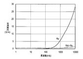
- FIG. 15 shows the ratio (Rp ratio) between the AC resistance due to the proximity effect at 100 kHz and the external magnetic field strength H of 1 A / mm and the AC resistance due to the proximity effect of the Cu wire as a reference (Rp ratio) for each conductor material. 48) shows the calculation result.
- the conductor portion 11 shown in FIG. 1A is made of pure aluminum
- the center conductor 12 shown in FIG. 1B is made of aluminum
- the cross-sectional area of the covering layer 13 is the entire wire. 1% (5% CCA), the central conductor 12 shown in FIG.
- the cross-sectional area of the covering layer 13 is 10% of the cross-sectional area of the entire wire (10% CCA)
- the central conductor 12 shown in FIG. 1B is made of aluminum
- the cross-sectional area of the covering layer 13 is 15% of the cross-sectional area of the entire electric wire (15% CCA)
- the central conductor 12 is made of alloy aluminum
- the cross-sectional area of the covering layer 13 is 5% of the cross-sectional area of the entire electric wire (5% CCA (alloy Al))
- FIG. 15 shows that there is a condition that the Rp ratio is less than 1 when the wire diameter is the same as that of the Cu wire and also when the wire diameter is larger than the Cu wire.
- the first embodiment of the present invention focuses on this Rp ratio. That is, in the electric wire according to the first embodiment of the present invention, in the specific frequency at which the electric wire is used, the AC resistance due to the proximity effect of the reference Cu wire is shown in FIG. 1 (a) and FIG. 1 (b).
- the volume resistivity of the conductor 11 is defined so that the ratio of the AC resistance (Rp ratio) due to the proximity effect of the conductor 11 shown is less than 1.
- the reference Cu wire may have the same wire diameter as the conductor portion 11 shown in FIGS. 1A and 1B or may have a different wire diameter, and can be set as appropriate.
- the AC resistance when used in a specific frequency band, the AC resistance can be equalized or reduced as compared with the reference Cu wire. .
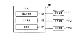
- the electric wire design apparatus includes a central processing unit (CPU) 110, a storage device 111, an input device 112, and an output device 113.
- CPU central processing unit
- the CPU 110 logically includes a resistance calculation unit 101, a ratio calculation unit 102, and a determination unit 103 as modules (logic circuits) that are hardware resources.
- the resistance calculation unit 101 reads out information on the wire type including the material, shape, wire diameter, and the like of the conductor unit 11 that is a candidate for a wire that can be produced from the storage device 111, and a specific frequency band in which the wire is used, Using the above-described equation (48), the AC resistance value due to the proximity effect of the conductor portion 11 that is a candidate for the electric wire in the specific frequency band is calculated. Furthermore, the resistance calculation unit 101 reads out information on the specific frequency band in which the electric wire is used and the reference Cu wire from the storage device 111, and uses the above-described equation (48) to determine the reference in the specific frequency band. The AC resistance value due to the proximity effect of the Cu wire to be calculated is calculated.
- the AC resistance value due to the proximity effect of the conductor part 11 and the Cu wire may be calculated at a plurality of frequencies within a specific frequency band range, and at least one frequency within the specific frequency band range (for example, a specific frequency band) The upper limit value of the frequency band may be calculated.
- the reference Cu wire may have the same wire diameter as the candidate conductor portion 11 or a different wire diameter, and can be set as appropriate.
- the ratio calculation unit 102 is a candidate conductor unit for the AC resistance value due to the proximity effect of the Cu wire at the same frequency based on the AC resistance value due to the proximity effect of the conductor portion 11 and the Cu wire calculated by the resistance calculation unit 101.
- the ratio of the AC resistance values (Rp ratio) due to the proximity effect of 11 is calculated.
- the determination unit 103 determines whether the candidate is applicable to the electric wire based on the Rp ratio calculated by the ratio calculation unit 102. For example, the determination unit 103 determines whether or not the Rp ratio is less than 1, and determines that the candidate is applicable to the electric wire when the Rp ratio is determined to be less than 1.
- the storage device 111 includes information on the equation (48) for obtaining the AC resistance due to the proximity effect, information on the plurality of candidate conductor portions 11, a specific frequency band used in each device to which the electric wire is applied, and the resistance calculation unit 101.
- the AC resistance value due to the proximity effect of the conductor part 11 and the Cu wire calculated by the above, the Rp ratio calculated by the ratio calculation part 102, the determination result by the determination part 103, and the like are stored.
- the storage device 111 for example, a semiconductor memory, a magnetic disk, an optical disk, or the like can be used.
- the storage device 111 can function as a storage device that stores a program executed by the CPU 110 (details of the program will be described later).
- the storage device 111 can temporarily store data and the like used during program execution processing in the CPU 110, and can function as a temporary data memory or the like used as a work area.
- a recognition device such as a touch panel, a keyboard, a mouse, or an OCR
- an image input device such as a scanner or a camera
- a voice input device such as a microphone
- a display device such as a liquid crystal display (LCD), an organic electroluminescence (EL) display, or a CRT display
- a printing device such as an inkjet printer or a laser printer, or the like can be used.
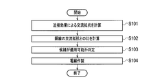
- step S101 the resistance calculation unit 101 reads out information on the conductor unit 11 that is a candidate for the electric wire and a specific frequency band in which the electric wire is used from the storage device 111, and uses the above-described formula (48). Thus, the AC resistance value due to the proximity effect of the conductor portion 11 in a specific frequency band is calculated. Furthermore, the resistance calculation unit 101 calculates the AC resistance value due to the proximity effect of the Cu wire as a reference, using the above-described equation (48). The calculated AC resistance value due to the proximity effect of the conductor part 11 and Cu is stored in the storage device 111. The AC resistance value due to the proximity effect of the conductor part 11 and Cu may be stored in advance in the storage device 111 or may be input from the input device 112. Further, the AC resistance value due to the proximity effect of the conductor part 11 and Cu may be measured instead of being calculated using a theoretical formula.
- step S102 the ratio calculation unit 102 determines the conductor part for the AC resistance value due to the proximity effect of the Cu wire based on the AC resistance value due to the proximity effect of the conductor portion 11 and the Cu wire calculated by the resistance calculation unit 101. The ratio of the AC resistance values (Rp ratio) due to the proximity effect of 11 is calculated.
- step S103 the determination unit 103 determines whether the Rp ratio calculated by the ratio calculation unit 102 is less than 1. As a result, when the Rp ratio is less than 1, it is determined that the candidate is applicable to the electric wire. The determination result is stored in the storage device 111.
- step S104 the electric wire is manufactured with the candidate material, shape, wire diameter, and the like determined to be applicable by the determination unit 103.
- a central conductor 12 made of aluminum or aluminum alloy having a diameter of about 9.5 mm to 12.0 mm is prepared.
- a coating layer 13 is formed on the surface of the central conductor 12 by performing TIG welding or plasma welding while applying a copper tape having a thickness of about 0.1 mm to 0.4 mm to the surface of the central conductor 12 by a vertical attachment method. Cover.
- the base conductor 12 made of the center conductor 12 covered with the covering layer 13 is manufactured by forming the center conductor 12 covered with the covering layer 13 into a diameter of about 9.3 mm to 12.3 mm using a skin pass.
- the base material is drawn by passing through a plurality of drawing dies of about 25 to 26 passes. By going through a plurality of wire drawing dies, the diameter of the electric wire is finally made the same as the determined wire diameter.
- the Rp ratio calculated using the equation (48) for obtaining the AC resistance due to the proximity effect is obtained. Based on this, the line type can be determined. As a result, depending on the specific frequency band in which the high-frequency wire is used, it is possible to design the wire diameter of the high-frequency wire that is less loss due to eddy currents and can reduce AC resistance compared to the reference Cu wire It becomes.
- step S102 shown in FIG. 17 the AC resistance value due to the proximity effect is calculated for each of the plurality of candidates.
- the Rp ratio is calculated for each of the plurality of candidates.
- step S103 the plurality of candidates are determined. You may determine whether each is applicable.
- step S104 if there are a plurality of applicable candidates, one of them may be selected as appropriate.
- ⁇ Wire design program> A series of procedures shown in FIG. 17, namely: (a) AC resistance due to proximity effect of conductor part 11 that is a candidate for a wire in a specific frequency band, and AC due to proximity effect of Cu wire as a reference in a specific frequency band (B) calculating the ratio of the AC resistance due to the proximity effect of the conductor part to the AC resistance due to the proximity effect of the Cu wire as a reference; (c) applying candidates to the wires based on the ratio The step of determining whether or not can be executed by controlling the electric wire design apparatus shown in FIG. 16 by an algorithm program equivalent to FIG.
- This program may be stored in the storage device 111 of the computer system constituting the electric wire designing apparatus of the present invention. Further, the program is stored in a computer-readable recording medium, and the recording medium is read into the storage device 111 or the like, whereby the series of procedures of the first embodiment of the present invention can be executed.
- “computer-readable recording medium” means a medium capable of recording a program, such as a semiconductor memory, a magnetic disk, and an optical disk.
- the main body of the electric wire design apparatus can be configured to incorporate a recording medium reader or to be externally connected. Further, it can be stored in the storage device 111 via an information processing network such as a wireless communication network.
- the electric wire according to the second embodiment of the present invention is an electric wire used in a specific frequency band, and as shown in FIG. 18, a center conductor 21 made of aluminum (Al) or an aluminum alloy, and a center conductor 2 is a CCA line provided with a coating layer 22 made of copper (Cu) that coats 21.
- the electric wire according to the second embodiment of the present invention is defined between the first frequency and the second frequency at which the AC resistance of the electric wire and the AC resistance of the Cu wire having the same wire diameter as the electric wire match.
- the specific frequency band is within a frequency band in which the AC resistance of the electric wire is larger than the AC resistance of the Cu wire.
- the diameter of the entire wire is preferably about 0.05 mm to 0.6 mm.
- the cross-sectional area of the covering layer 22 is 15% or less with respect to the cross-sectional area of the entire electric wire including the central conductor 21 and the covering layer 22, preferably about 3% to 15%, more preferably about 3% to 10%. More desirably, it is about 3% to 5%. High frequency resistance can be reduced, so that the ratio of the cross-sectional area with respect to the whole electric wire of the coating layer 22 is small.
- an aluminum alloy of electrical aluminum (EC aluminum) or an Al—Mg—Si alloy (JIS 6000 series) can be used as the central conductor 21.
- the aluminum alloy has a larger volume resistivity than EC aluminum. Therefore it is more desirable.
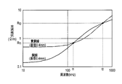
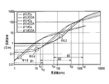
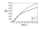
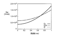
- FIG. 19 shows the relationship between frequency and AC resistance for CCA wires and Cu wires having wire diameters of 1.8 mm, 0.4 mm, and 0.2 mm.
- the AC resistance of the CCA wire is larger than the AC resistance of the Cu wire on the lower frequency side than the first frequency f11 (not shown) of about 1 kHz.
- the AC resistance of the CCA line coincides with the AC resistance of the Cu line, and eddy current loss becomes dominant on the higher frequency side than the first frequency f11.
- the magnitude of the AC resistance of the line is reversed.
- the AC resistance of the Cu line is larger than the AC resistance of the CCA line.
- the AC resistance of the CCA line again coincides with the AC resistance of the Cu line, and on the higher frequency side than the second frequency f12, the influence of the proximity effect of the CCA line becomes larger than that of the Cu line.
- the magnitudes of the AC resistance of the wire and the AC resistance of the Cu wire are reversed.
- the AC resistance of the CCA wire and the AC resistance of the Cu wire coincide with each other at the first frequency f21 and the second frequency f22.
- the AC resistance of the Cu line is larger than the AC resistance of the CCA line.
- the AC resistance of the CCA wire and the AC resistance of the Cu wire coincide with each other at the first frequency f31 and the second frequency f32.
- the AC resistance of the Cu line is larger than the AC resistance of the CCA line.
- the first frequency f11 and the second frequency f12 shift to the high frequency side as the diameters of the CCA line and the Cu line are reduced to 1.8 mm, 0.4 mm, and 0.2 mm.
- the frequency bands B1, B2, and B3 defined between the first frequencies f11, f21, and f31 and the second frequencies f12, f22, and f32 were found to shift to the high frequency side. Even if the strength of the magnetic field increases, the second frequencies f12, f22, and f32 hardly change, but the first frequencies f11, f21, and f31 move to the low frequency side.
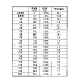
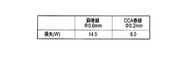
- the loss (copper loss) generated in the high-frequency transformer is the sum of the DC component, the reference frequency, and the higher-order harmonic component.
- the loss of the 0.2 mm diameter CCA winding according to the second embodiment of the present invention is 8.0 W
- the loss of the 0.6 mm diameter copper winding according to the comparative example. Is 14.5W.
- the frequency band of the alternating current used for the CCA line is defined by the first frequency f11, f21, f31 and the second frequency f12, f22, f32 from the reference frequency to the higher order harmonic components. It is preferable that the diameter, material, cross-sectional area ratio, and the like of the CCA line are designed so as to be within the frequency bands B1, B2, and B3. To what extent higher-order harmonic components are taken into consideration may be determined as appropriate according to the use of the CCA line. For example, from the reference frequency to the 10th harmonic component may be considered, or from the reference frequency to the 20th harmonic component may be considered.
- the loss due to eddy current when used in a specific frequency band, is equal to or smaller than that of a Cu wire having the same wire diameter. AC resistance can be reduced.
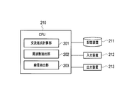
- the electric wire design apparatus includes a central processing unit (CPU) 210, a storage device 211, an input device 212, and an output device 213.
- CPU central processing unit
- the CPU 210 logically includes an AC resistance calculation unit 201, a frequency extraction unit 202, and a wire diameter extraction unit 203 as modules (logic circuits) that are hardware resources.
- the AC resistance calculation unit 201 reads information necessary for calculating the AC resistance of the target CCA line and Cu line from the storage device 211, and, as shown in FIG. 19, according to a plurality of frequencies, the CCA line And AC resistance of Cu wire having the same wire diameter as CCA wire are calculated for each of a plurality of wire diameters.
- the frequency extraction unit 202 Based on the AC resistance of the CCA line calculated by the AC resistance calculation unit 201 and the AC resistance of the Cu wire having the same wire diameter as the CCA line, the frequency extraction unit 202, for each of a plurality of wire diameters, as shown in FIG.
- f12, f22, and f32 are extracted (f11 is not shown).
- the frequency extracted as the first frequencies f11, f21, and f31 and the second frequencies f12, f22, and f32 may not be a point where the AC resistance of the CCA line and the AC resistance of the Cu line exactly match.
- the frequency immediately before (low frequency side) or just after (high frequency side) switching between the AC resistance of the CCA line and the AC resistance of the Cu line may be extracted, or the AC resistance of the CCA line and the AC resistance of the Cu line. It is also possible to obtain respective approximate curves from the calculation results and extract the frequencies at which these approximate curves intersect.
- the wire diameter extraction unit 203 reads the specific frequency band in which the CCA line is used from the storage device 211, and extracts the first frequencies f11, f21, f31 and the second frequencies f12, f22, f31 extracted by the frequency extraction unit 202. Based on f32, among the plurality of wire diameters, the frequency bands B1, B2, and B3 defined between the extracted first frequencies f11, f21, and f31 and the second frequencies f12, f22, and f32 are CCA.
- the diameter of the CCA line corresponding to the first frequency and the second frequency such that the line falls within the specific frequency band used (for example, the diameter 0 corresponding to the first frequency f21 and the second frequency f22). .4 mm).
- the specific frequency band in which the CCA line is used may include, for example, the reference frequency and the 10th and lower harmonic frequencies shown in FIG. 21, and include the reference frequency and the 20th and lower harmonic frequencies. May be.
- the storage device 211 shown in FIG. 23 includes information necessary for calculating the AC resistance of CCA wires and Cu wires having various wire diameters, a specific frequency band in which each CCA line is used, and an AC resistance calculation unit 201.
- the first resistances f11, f21, f31 and the second frequencies f12, f22, f32 extracted by the frequency extraction unit 202 and the wire diameter of the CCA line extracted by the wire diameter extraction unit 203 are stored.
- a semiconductor memory, a magnetic disk, an optical disk, or the like can be employed.
- the storage device 211 can function as a program storage device or the like that stores a program executed by the CPU 210 (details of the program will be described later).
- the storage device 211 can temporarily store data and the like used during the program execution process in the CPU 210, or can function as a temporary data memory or the like used as a work area.
- a recognition device such as a touch panel, a keyboard, a mouse, or an OCR
- an image input device such as a scanner or a camera
- a voice input device such as a microphone
- the output device 213 a display device such as a liquid crystal display (LCD), an organic electroluminescence (EL) display, or a CRT display, or a printing device such as an ink jet printer or a laser printer can be used.
- LCD liquid crystal display
- EL organic electroluminescence
- CRT display or a printing device such as an ink jet printer or a laser printer
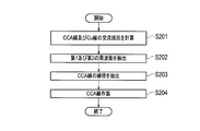
- step S201 the AC resistance calculation unit 201 calculates the AC resistance of the CCA line and the AC resistance of the Cu line having the same wire diameter as the CCA line for each of the plurality of wire diameters. This calculation result is stored in the storage device 211.
- the material and cross-sectional area ratio of the CCA line to be calculated can be set as appropriate.
- the AC resistance of the CCA line and the AC resistance of the Cu line may be actually measured instead of being calculated.
- step S202 the frequency extraction unit 202 matches the AC resistance of the CCA line and the AC resistance of the Cu line for each of the plurality of wire diameters, and the CCA line
- the range of the wire diameter and the frequency range to be calculated can be appropriately set within the range that can be used as the CCA line.
- the extracted first frequencies f11, f21, and f31 and second frequencies f12, f22, and f32 are stored in the storage device 211.
- the wire diameter extraction unit 203 defines a frequency defined between the extracted first frequencies f11, f21, and f31 and the second frequencies f12, f22, and f32 among the plurality of wire diameters.
- the diameters of the CCA lines corresponding to the first frequency and the second frequency (for example, the first frequency f11 and the second frequency) such that the bands B1, B2, and B3 are within a specific frequency band using the CCA line.
- a wire diameter of 1.8 mm corresponding to the frequency f12 is extracted.
- the extracted wire diameter is stored in the storage device 211.
- a CCA strand having a wire diameter stored in the storage device 211 is manufactured. That is, a central conductor 21 made of aluminum or aluminum alloy having a diameter of about 9.5 mm to 12.0 mm is prepared. A coating layer 22 is formed on the surface of the central conductor 21 by performing TIG welding or plasma welding or the like while applying a copper tape having a thickness of about 0.1 mm to 0.4 mm to the surface of the central conductor 21 by a vertical attachment method. Cover. Next, the base conductor 21 made of the center conductor 21 covered with the covering layer 22 is manufactured by forming the center conductor 21 covered with the covering layer 22 into a diameter of about 9.3 mm to 12.3 mm using a skin pass. Next, the base material is drawn by passing through a plurality of drawing dies of about 25 to 26 passes. By going through a plurality of wire drawing dies, the diameter of the electric wire is finally made the same as the wire diameter stored in the storage device 211.
- the same wire diameter is used according to the specific frequency band in which the CCA wire is used.
- the loss due to eddy current can be made equal to or smaller than that of the Cu wire, and the diameter of the CCA wire that can reduce the AC resistance can be designed.
- the first frequencies f11, f21, f31 and the second frequencies f12, f22, f2 and f22 such that the frequency bands B1, B2, B3 defined between f22 and f32 fall within a specific frequency band using the CCA line.
- f32 Step extracting a wire diameter of, or the like, by 24 equivalent algorithm program, wire design device control to be executed as shown in FIG. 23.
- This program may be stored in the storage device 211 of the computer system constituting the electric wire designing apparatus of the present invention.
- the program is stored in a computer-readable recording medium, and the recording medium is read into the storage device 211 or the like, whereby the series of procedures according to the second embodiment of the present invention can be executed.
- “computer-readable recording medium” means a medium capable of recording a program, such as a semiconductor memory, a magnetic disk, and an optical disk.
- the main body of the electric wire design apparatus can be configured to incorporate a recording medium reader or to be externally connected. Further, it can be stored in the storage device 211 via an information processing network such as a wireless communication network.
- An electric motor that adjusts rotational speed and torque using an inverter device or the like is highly efficient, and is used in a wide range of fields such as inverter air conditioners in the drive of railway vehicles and electric vehicles, and home appliances.
- the coil of the electric motor is constructed by winding a conducting wire multiple times.
- Cu copper
- Al aluminum
- Cu wires are generally used for conventional coils.
- this type of electric motor has a variable rotation speed and is often used at a high rotation speed.
- the drive current of the electric motor has a higher frequency according to the rotation speed.
- the inverter device creates a high frequency by appropriately turning on and off the DC voltage. For this reason, the drive current has a higher frequency component than the fundamental frequency component.
- the resistance of the coil increases due to the skin effect and proximity effect.
- the resistance due to the skin effect is always greater for the Al line than for the Cu line, but the resistance due to the proximity effect may be greater for the Cu line.
- the high frequency resistance may increase due to the proximity effect, and the loss due to this may increase. In particular, the loss becomes significant when the operating frequency becomes high or when the inverter device is used for driving.
- the coil has various shapes, and if the shape is different, the ratio of the skin effect and the proximity effect in the high-frequency resistance of the conductive wire is different.
- the skin effect is determined by the cross-sectional shape of the conducting wire constituting the coil, the number of conducting wires, and the length of the conducting wire, but the proximity effect also depends on how the coil is wound. When a conducting wire is wound in the vicinity or the number of turns is large, the proximity effect becomes strong.
- the high frequency resistance per unit length of the conducting wire constituting the coil can be expressed as the following equation (49).
- R ac R s + ⁇ 2 P p (49)
- R s unit: ⁇ / m
- P p unit: ⁇ ⁇ m
- ⁇ The unit is 1 / m
- ⁇ is a shape factor (structure factor) depending on the shape of the coil.
- ⁇ is a constant substantially independent of frequency, and becomes larger when the coil winding is densely wound, and becomes larger as the winding wire is longer.
- ⁇ varies depending on the required output of the electric motor and the like.
- R s and P p are given by the following equations (50) and (51), respectively.
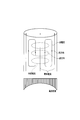
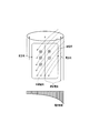
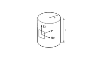
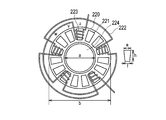
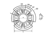
- the electric motor (three-phase AC synchronous motor) according to the first example of the second embodiment of the present invention includes a plurality of iron cores 221 arranged in a circular shape, and an Al wire.
- the electric wire 222 which consists of a CCA wire is provided with the some coil 223 wound around the some iron core 221, and the rotor 224 rotated by applying an electric current to the some coil 223.
- a plurality of iron cores 221, a plurality of coils 223, a coil holding part 20, and the like constitute a stator.
- the electric motor according to the first example of the second embodiment of the present invention is 12 coils, the inner diameter a of the coil holding part 20 is 150 mm, the outer diameter b of the coil holding part 20 is 200 mm, and the length of the iron core 221 is long.
- the length h is 40 mm, the diameter e of one end on the outer peripheral side of the iron core 221 is 30 mm, and the diameter f of the other end of the iron core 221 is 20 mm.
- Each pole is wound around the iron core 21 in a cylindrical shape by an electric wire 222 having a radius r of 0.8 mm, and the total length l is about 3.1 m.
- the u-phase coil 223 is shown in FIG. 25, the v-phase and w-phase coils that are not shown also have the same structure as the coil 223.
- the rotor 224 is made of a permanent magnet.
- the rotor 224 is attracted and rotated by the surrounding rotating magnetic field generated by the alternating current applied to the coil 223.
- the electric motor according to the first example of the second embodiment of the present invention uses a variable voltage variable frequency (VVVF) type inverter device, and adjusts the frequency of the drive current in an inverter manner, thereby providing an electric motor.
- VVVF variable voltage variable frequency
- the inverter device is, for example, a three-phase output inverter using six switching elements, and artificially creates a three-phase alternating current using the switching elements.
- the AC resistance of the coil 223 falls between the first frequency that is smaller than the AC resistance of the coil wound with the Cu wire having the same shape as the coil 223 and the second frequency that is higher than the first frequency.
- the frequency of the alternating current applied to the coil 223 is controlled by the inverter method.
- the drive current has, for example, a high frequency component having an amplitude of 1/3 or more of the fundamental frequency component, and a power having a high frequency component having 1/9 or more of the fundamental frequency component.
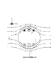
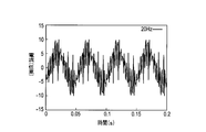
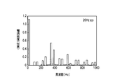
- 26 and 27 show current waveforms when the operating frequency is 20 Hz and 50 Hz, respectively, in the electric motor shown in FIG. FIG. 28 is obtained by extending the time axis of FIG. 27 by 2.5 times and superimposing it on FIG. According to FIG. 26, the current has a basic period of 0.05, but since there is an inverter system that cuts out a variable voltage and generates a high frequency, there are many places where the sinusoidal waveform changes rapidly. In FIG. 27, the fundamental period is 0.02 s. From FIG. 28, it can be seen that the configuration of the sine wave waveform is almost constant without depending on the frequency.
- FIG. 29 represents the frequency spectrum of FIG. As shown in FIG. 29, it can be seen that in addition to the fundamental frequency of 20 Hz, there are many high-frequency components. The high-frequency resistance becomes higher than the presence of these high-frequency components, and the loss due to the proximity effect becomes more remarkable.
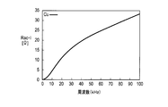
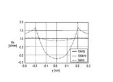
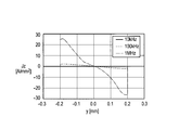
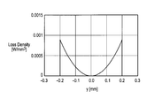
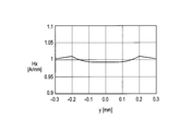
- FIG. 30 shows a high-frequency resistance R s per unit length due to the skin effect when a coil is wound with Cu wire having a radius r of 0.8 mm and a length l of 3.1 m, and an external magnetic field H 0.
- H 0 1A / mm
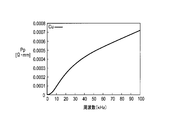
- the loss P P per unit length due to the proximity effect in Figure 31.
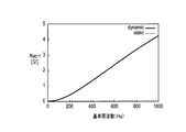
- the coil wound with the same Cu wire shows the static characteristic of the high frequency resistance as shown in FIG.
- the static characteristics refer to characteristics when a sinusoidal current is passed through the electric motor.
- f n is the frequency of the n-th order frequency components.
- the drive current in FIG. 26 is created by the inverter device, and assuming that the waveform constituting the sine wave does not change relatively even if the frequency changes, and calculating the dynamic characteristics of the high frequency resistance of the coil by the equation (52), The calculation result shown in FIG. 33 is obtained.
- the dynamic characteristics refer to characteristics when a periodic drive current as shown in FIG. 26 is passed through the electric motor.
- the fundamental frequency is the reciprocal of the driving current cycle. It can be seen from FIG. 33 that the dynamic characteristic (dynamic) is much larger than the static characteristic (static).
- the electric wire 222 around which the coil 223 is wound has the same diameter, and aluminum (Al) or aluminum as shown in FIG.
- a CCA line (hereinafter referred to as “CCA line”) comprising a central conductor 21 made of an alloy and a covering layer 22 made of copper (Cu) covering the central conductor 21, wherein the cross-sectional area of the covering layer 22 is 5% of the cross-sectional area of the entire high-frequency electric wire.
- CCA line a CCA line
- Cu copper
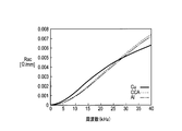
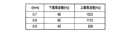
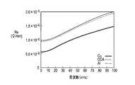
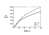
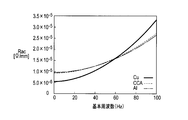
- the dynamic characteristics of the high frequency resistance of the coil wound with the same CCA wire and Al wire are shown in FIG. 36 and FIG. 36 and 37 that the resistance of the CCA line and the Al line is smaller than that of the Cu line when the frequency f is in the range of 65 Hz ⁇ f ⁇ 1173 Hz.
- the first frequency is set to 65 Hz
- the second frequency is set to 1173 Hz
- the frequency of the drive current is controlled in the range of 65 Hz ⁇ f ⁇ 1173 Hz, thereby obtaining a high-frequency resistance equivalent to or smaller than the Cu wire. be able to.
- the first frequency and the second frequency at which each of the CCA line and the Al line has a high frequency resistance equivalent to or lower than that of the Cu line can be expressed by the following equations (49) to (52). It may be obtained by calculation using it, or may be obtained by actual measurement.
- the electric wire 222 having a circular cross section has been described.
- the cross sectional shape of the electric wire 222 may be flat or rectangular, and the cross sectional area is 2.0 mm 2. If so, the same effect is obtained in the case of the CCA line.
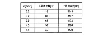
- the density of the winding of the electric motor used and the length of the conducting wire are changed, the same effect can be obtained even when ⁇ is changed to 2.2 mm ⁇ 1 ⁇ ⁇ ⁇ 5.5 mm ⁇ 1 .
- FIG. 38 shows a frequency band in which the dynamic characteristic high-frequency resistance of the CCA wire for different ⁇ values is smaller than that of the Cu wire in a coil wound with the same shape of conducting wire. It can be seen that the frequency band in which the CCA line is advantageous increases as ⁇ increases (for example, as the conducting wire is tightly wound or wound many times).
- the Al wire or the CCA wire having lower conductivity than the Cu wire is used, and the first inverter is used.
- the frequency of the drive current between the frequency and the second frequency it is possible to reduce the high-frequency resistance equivalent to or lower than that of the Cu wire and the loss of the electric motor.
- Al is lighter than copper (Cu)
- Cu copper
- the CCA wire when used, since it can be soldered as in the past, the high frequency resistance can be reduced and the weight can be reduced without impairing the workability. Further, when the skin depth of the CCA wire is about the thickness of the copper layer, the loss due to the skin effect is about the same as that of the conventional conductor.
- an electric motor (three-phase AC synchronous motor) according to a second example of the second embodiment of the present invention includes a plurality of iron cores 221 arranged in a circle and an Al wire.
- the electric wire 222 which consists of a CCA wire is provided with the some coil 223 wound around the some iron core 221, and the rotor 224 rotated by applying an electric current to the some coil 223.
- the electric motor according to the second example of the second embodiment of the present invention has 15 coils, the inner diameter a of the coil holding part 20 is 170 mm, the outer diameter b of the coil holding part 20 is 220 mm, and the length of the iron core 221.
- the length h is 45 mm
- the diameter e of one end on the outer peripheral side of the iron core 221 is 33 mm
- the diameter f of the other end of the iron core 221 is 25 mm.
- Each pole is wound around the iron core 21 in a cylindrical shape by an electric wire 222 having a radius r of 1.0 mm, and the total length l is about 4.8 m.
- the u-phase coil 223 is shown in FIG. 40, the v-phase and the w-phase also have the same coil structure as the coil 223.
- a 5% CCA line and an Al line having a radius r of 1.0 mm and a length of 4.8 m are used, and Cu is used as a comparative example.
- a line was used.
- the coil wound with these conducting wires exhibits high-frequency resistance static characteristics as shown in FIGS.
- FIG. 45 and FIG. 46 show the high-frequency resistance dynamic characteristics when it is assumed that the drive current of FIG. 26 is generated by an inverter and the waveform constituting the sine wave does not change relatively even if the frequency changes.
- the frequency f is 59 Hz ⁇ f ⁇ 742 Hz and the resistance of the CCA line and the Al line is smaller than that of the Cu line.
- the first frequency is set to 59 Hz
- the second frequency is set to 742 Hz
- the frequency of the drive current is controlled in a range of 59 Hz ⁇ f ⁇ 742 Hz, thereby obtaining a high-frequency resistance equivalent to or smaller than the Cu line. be able to.
- the electric wire 222 having a circular cross section has been described.
- the cross section of the electric wire 222 may be flat or rectangular, and the cross sectional area is 3.1 mm 2. If so, the same effect is obtained in the case of the CCA line.
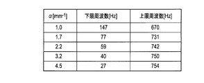
- the value of ⁇ is 1. The same effect can be obtained even when .0 mm ⁇ 1 ⁇ ⁇ ⁇ 4.5 mm ⁇ 1 is changed.
- FIG. 47 shows a frequency band in which the dynamic characteristic high-frequency resistance of the CCA wire for different ⁇ values is smaller than that of the Cu wire in a coil wound with the same shape of conducting wire. It can be seen that the frequency band in which the CCA line is more advantageous than the Cu line is widened as the value of ⁇ increases (as it is tightly wound or wound more).
- an electric motor (three-phase AC synchronous motor) according to a third example of the second embodiment of the present invention has a plurality of iron cores 221 and an electric wire 222 made of Al wires or CCA wires. Includes a plurality of coils 223 wound around a plurality of iron cores 221 and a rotor 224 that rotates by applying a current to the plurality of coils 223.
- the electric motor according to the third example of the second embodiment of the present invention has 18 coils, the inner diameter a of the coil holding part 20 is 180 mm, the outer diameter b of the coil holding part 20 is 230 mm, and the length of the iron core 221 is long.
- the length h is 50 mm
- the diameter e of one end on the outer peripheral side of the iron core 221 is 36
- the diameter f of the other end of the iron core 221 is 27 mm
- each pole has a cylindrical shape with an electric wire 222 having a radius r of 1.2 mm.
- the total length l was about 7.0 m.
- FIG. 49 only the u-phase coil is shown, but the v-phase and w-phase coils, which are not shown, also have the same structure as the coil 223.
- a 5% CCA wire and an Al wire having a radius r of 1.2 mm and a length of 7.0 m are used, and a Cu wire is used as a comparative example. It was used.
- the outer diameter b of the coil holding part 20 was 1.17 mm, and the inner diameter a of the coil holding part 20 was 1.2 mm.
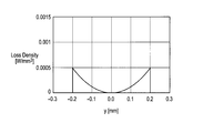
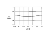
- the frequency resistance R s per unit length due to the skin effect of the case shown in FIG. 50, when the external magnetic field H 0 and H 0 1A / mm, Figure loss P P per unit length due to the proximity effect 51 Shown in
- the coil wound by these conducting wires shows the static characteristic of a high frequency resistance as shown in FIG.52 and FIG.53.
- FIG. 54 and FIG. 55 show the high-frequency resistance dynamic characteristics when it is assumed that the drive current of FIG. 26 is generated by an inverter device and the waveform constituting the sine wave does not change relatively even if the frequency changes.
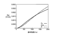
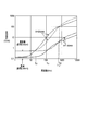
- the frequency f is 48 Hz ⁇ f ⁇ 511 Hz and the resistance of the CCA line and the Al line is smaller than that of the Cu line.
- the first frequency to 48 Hz and the second frequency to 511 Hz and controlling the frequency of the drive current at 48 Hz ⁇ f ⁇ 511 Hz
- a high frequency resistance equivalent to or smaller than the Cu wire can be obtained. .
- the electric wire 222 having a circular cross section has been described.
- the cross sectional shape of the electric wire 222 may be flat or rectangular, and the cross sectional area is 4.5 mm 2. If so, the same effect is obtained in the case of the CCA line.
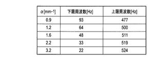
- alpha is 0.9mm -1 ⁇ ⁇ ⁇ 3. The same effect is obtained even when the value is changed to 2 mm ⁇ 1 .
- FIG. 56 shows a frequency band in which the dynamic high frequency resistance of the CCA line for different ⁇ values is smaller than that of the Cu line in a coil wound with the same shape of conducting wire. From FIG. 56, it can be seen that the frequency band in which the CCA line is advantageous increases as ⁇ becomes larger (closer or more wound).
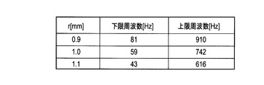
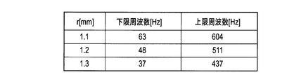
- FIG. 57 shows a frequency band where the CCA line has a lower dynamic characteristic high frequency resistance than the Cu line when the value of ⁇ is 1.6 mm ⁇ 1 and the radius r is different. From FIG. 57, it can be seen that the thicker the wire diameter, the more advantageous the CCA line on the low frequency side.
- CCA wires and Cu wires having wire diameters of 1.8 mm, 0.4 mm, and 0.2 mm have been described.
- the present invention is not particularly limited to these three wire diameters.
- the present invention may be applied to CCA wires and Cu wires having various wire diameters.
- the electric wire according to the present invention is an electric motor using various coils.
- the present invention can be applied to a motor, and the electric motor according to the present invention can be applied to various types of electric motors having a coil wound with a CCA wire or an Al wire.
- the electric wire according to the third embodiment of the present invention includes a conductor portion 31 made of a material having a higher volume resistivity than copper.
- the AC resistance of the electric wire and the AC resistance of the Cu wire having the same wire diameter as the electric wire match each other, and the AC resistance of the electric wire is Cu wire between each other.
- the volume resistivity of the conductor portion 31 is set so that the second frequency is equal to or higher than the upper limit value of the specific frequency band among the first frequency smaller than the AC resistance and the second frequency larger than the first frequency.
- the DC resistance value per unit length divided by the cross-sectional area is specified.
- the diameter of the conductor portion 31 is preferably about 0.05 mm to 0.6 mm, but is not particularly limited.
- copper alloys such as brass, phosphor bronze, quartz bronze, copper-beryllium alloy, and copper-nickel-silicon alloy, can be used.
- Brass is an alloy (Cu—Zn) containing copper (Cu) and zinc (Zn), and may contain a small amount of elements other than copper and zinc.
- Silica bronze is an alloy (Cu—Sn—Si) containing copper, tin (Sn) and silicon (Si), and may contain a small amount of elements other than copper, tin and silicon.
- Phosphor bronze is an alloy (Cu—Sn—P) containing copper, tin and phosphorus (P), and may contain a small amount of elements other than copper, tin and phosphorus.
- These copper alloy wires are, for example, one-principle annealed and may be plated with tin, copper, chromium (Cr), or the like. Further, the conductor portion 31 may have a flat shape or the like in addition to the cylindrical shape.
- the electric wire according to the third embodiment of the present invention includes a central conductor 32 made of aluminum (Al) or an aluminum alloy, and copper (Cu) covering the central conductor 32.
- the CCA line provided with the covering layer 33 made of may be used as the conductor portion 31.
- the diameter of the entire CCA line is preferably about 0.05 mm to 0.6 mm.
- the cross-sectional area of the covering layer 33 is 15% or less with respect to the cross-sectional area of the entire electric wire including the central conductor 32 and the covering layer 33, preferably about 3% to 15%, more preferably about 3% to 10%. More desirably, it is about 3% to 5%. High frequency resistance can be reduced, so that the ratio of the cross-sectional area with respect to the whole electric wire of the coating layer 33 is small.
- the center conductor 32 for example, an aluminum alloy of electrical aluminum (EC aluminum) or an Al—Mg—Si based alloy (JIS6000 series) can be used, but the aluminum alloy has a larger volume resistivity than EC aluminum. Therefore it is more desirable.
- the electric wire according to the third embodiment of the present invention has a smaller eddy current loss than a Cu wire having the same wire diameter due to the proximity effect in a specific frequency band, resulting in a smaller AC resistance. I found the characteristics.
- FIG. 13 shows the relationship between the frequency and the AC resistance when the external magnetic field strength H is 1 A / mm for the brass wire having a wire diameter of 0.4 mm and the Cu wire as a comparative example.
- the AC resistance of the brass wire is larger than the AC resistance of the Cu wire.
- the AC resistance of the brass wire matches the AC resistance of the Cu wire, and eddy current loss becomes dominant on the higher frequency side than the first frequency f1, so the AC resistance of the brass wire and Cu
- the magnitude of the AC resistance of the line is reversed.
- the AC resistance of the Cu wire is larger than the AC resistance of the brass wire.
- the AC resistance of the brass wire again coincides with the AC resistance of the Cu wire, and on the higher frequency side than the second frequency f2, the influence of the proximity effect of the brass wire becomes larger than that of the Cu wire, and brass.
- the magnitudes of the AC resistance of the wire and the AC resistance of the Cu wire are reversed.
- FIG. 14 shows the relationship between the frequency when the external magnetic field strength H for a brass wire having a diameter of 0.4 mm is 1 A / mm, the sum of the skin effect component R s and the DC resistance component R dc , and the proximity effect component R p. .
- DC resistance R dc the frequency is a value of the AC resistance at 0.
- the skin effect component R s and the proximity effect component R p have frequency dependence, but as shown in FIG. 14, if the frequency is less than 1 MHz, the proximity effect component R p is more than the skin effect component R s. The dependence is remarkable, and the skin effect component R s is a negligible level.
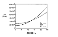
- FIG. 59 shows the relationship between the frequency and the AC resistance when the external magnetic field strength H of the brass wire and the Cu wire having a diameter of 0.4 mm is 1 A / mm and 5 A / mm, respectively.
- the proximity effect component R p is a significant field strength-dependent than the skin effect component R s.
- AC resistance R ac of the second frequency f12, f22 proximity effect component R p accounts for most of the second to the magnetic field strength is proportional to uniformly increase the Cu lines and brass wire both be increased The frequencies f12 and f22 hardly change.
- the first frequency f11, f21 is large influence of the DC resistance component R dc is the proximity effect component R p between the external magnetic field strength increases is shifted to the low frequency side increases.
- the direct current resistance per unit length obtained by dividing the volume resistivity of the metal applied to the conductor by the cross-sectional area is defined as “reference direct current resistance”.
- the reference DC resistance and the second frequency were obtained by calculation using the conductor material and wire diameter.
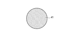
- the conductor portion 31 shown in FIG. 58 (a) is made of pure aluminum
- the central conductor 32 shown in FIG. 58 (b) is made of aluminum
- the cross-sectional area of the covering layer 33 is an electric wire.
- 5% CCA 5% of the entire cross-sectional area
- the cross-sectional area of the covering layer 33 is 10% of the cross-sectional area of the entire electric wire (10 % CCA)
- the central conductor 32 shown in FIG. 58 (b) is made of aluminum
- the cross-sectional area of the covering layer 33 is 15% of the cross-sectional area of the entire wire (15% CCA), shown in FIG. 58 (b).
- the central conductor 32 is made of alloy aluminum
- the cross-sectional area of the covering layer 33 is 5% of the cross-sectional area of the entire electric wire (5% CCA (alloy Al))
- Each made of brass, quartz bronze and phosphor bronze It shows the calculated results for things.
- the volume resistivity of the CCA line was an equivalent volume resistivity obtained by conversion with the cross-sectional area ratio of the two layers.
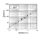
- a regression line as shown by a solid line in FIG. 61 was obtained. That is, the reference DC resistance Rdc, the second frequency as f 2, has been found to be the following relationship (49).
- the electric wire according to the third embodiment of the present invention uses the formula (53), and the reference of the conductor portion 31 so as to have the second frequency equal to or higher than the upper limit value of the specific frequency band in which the electric wire is used.
- DC resistance value is specified. That is, the volume resistivity, the cross-sectional area, the material, the shape, the wire diameter, and the like of the conductor portion 31 are defined so that the reference DC resistance value is obtained.
- the second frequency is set to, for example, about 100 kHz or more, and thus the reference DC resistance is set to about 0.55 m ⁇ / cm or more. It is desirable to set to.
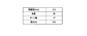
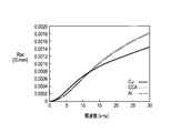
- the brass wire which concerns on the 3rd Embodiment of this invention uses 17 strands of diameter 0.4mm, length 6.6m, and 17 turns.
- a magnetic field generating coil for an IH cooker was produced with a litz wire structure, and a characteristic confirmation test was performed on them.
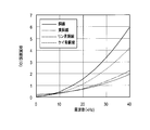
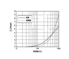
- the test results are shown in FIGS.
- a high frequency current of about 20 kHz to 60 kHz is generally used for an IH cooker, but it can be seen that the AC resistance of the brass wire is smaller than the AC resistance of the Cu wire in a frequency band including about 20 kHz to 60 kHz. .
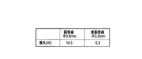
- the loss (copper loss) generated in the high-frequency transformer is the sum of the DC component, the reference frequency, and the higher-order harmonic component.
- the loss of the 0.2 mm diameter brass winding according to the third embodiment of the present invention is 5.3 W
- the loss of the 0.6 mm diameter copper winding according to the comparative example. Is 14.5W.
- the second frequency is set to be higher than the higher harmonic component of the alternating current used.
- higher-order harmonic components may be appropriately determined according to the use of the electric wire. For example, from the reference frequency to the 10th harmonic component may be considered, or from the reference frequency to the 20th harmonic component may be considered.
- the reference direct current of the conductor portion 31 of the electric wire is used so that the second frequency becomes equal to or higher than the upper limit value of the specific frequency band using the equation (53). Resistance value is specified.
- FIG. 61 shows two broken lines of 0.7 times and 1.3 times of the regression line shown by the solid line.
- the reference DC resistance value is defined within the bandwidth range between the two broken lines shown in FIG. May be. That is, the reference DC resistance value R dc of the high-frequency electric wire according to the third embodiment of the present invention is set to a second frequency f 2 , 0.7 ⁇ 10 (0.925 ⁇ log Rdc + 2.24) ⁇ f 2 ⁇ 1.3 ⁇ 10 (0.925 ⁇ log Rdc + 2.24) (54) You may prescribe in relation to.
- the reference DC resistance value can be widened in an effective range, and the degree of freedom in designing the volume resistivity, cross-sectional area, material, shape, wire diameter, etc. of the conductor portion 31 that defines the reference DC resistance value. Can be improved.
- the reference DC resistance value R dc is set to an upper limit value f 0 of a specific frequency band, f 0 ⁇ 10 (0.925 ⁇ log Rdc + 2.24) (55) You may prescribe
- the second frequency can be set to be equal to or higher than the upper limit value of the specific frequency band, and the reference DC resistance value can be specified in a range satisfying the relationship of Expression (55), so that the reference DC resistance value is specified.
- the degree of freedom in design such as volume resistivity, cross-sectional area, material, shape, and wire diameter of the conductor portion 31 can be improved.
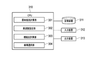
- the electric wire design apparatus includes a central processing unit (CPU) 310, a storage device 311, an input device 312, and an output device 313.
- CPU central processing unit
- the CPU 310 logically includes a specific resistance calculation unit 301, a frequency setting unit 302, a target resistance calculation unit 303, and a line type selection unit 304 as modules (logic circuits) that are hardware resources.
- the specific resistance calculation unit 301 reads necessary information from the storage device 311 and calculates a specific reference DC resistance value for each line type including a combination of a material, a shape, a wire diameter, and the like that can be produced.
- the reference DC resistance value for each line type may be stored in advance in the storage device 311 or may be input from the input device 312.
- the frequency setting unit 302 reads a specific frequency band in which the designed electric wire is used from the storage device 311, and the AC resistance of the electric wire and the AC resistance of the Cu wire having the same wire diameter as the electric wire match each other.
- the second frequency is a value equal to or higher than the upper limit value of the specific frequency band.
- the second frequency is set so that the second frequency matches the upper limit value of a specific frequency band.
- the upper limit value of the specific frequency band for example, the second frequency may be set higher than the 10th harmonic frequency, or the second frequency may be set higher than the 20th harmonic frequency. good.
- the target resistance calculation unit 303 calculates a target reference DC resistance value from the second frequency set by the frequency setting unit 302 using the equation (53) or the equation (54). Further, the target resistance calculation unit 303 reads a specific frequency band in which the electric wire designed by the storage device 311 is used, and calculates a target reference DC resistance value so as to satisfy the relationship of Expression (55). good.
- the line type selection unit 304 selects the type of electric wire according to the reference DC resistance value calculated by the specific resistance calculation unit 301 and the target resistance calculation unit 303, respectively. That is, the line type selection unit 304 has the reference DC resistance value specific to the plurality of line types calculated by the specific resistance calculation unit 301 among the plurality of line types as the target calculated by the target resistance calculation unit 303. Select a line type that is greater than or equal to the reference DC resistance value.
- the storage device 311 is information necessary to calculate the reference DC resistance values of a plurality of line types, a specific frequency band used in each device to which the electric wire is applied, and information related to Expression (53) or Expression (54). , The reference DC resistance value calculated by the specific resistance calculation unit 301, the second frequency set by the frequency setting unit 302, the reference DC resistance value calculated by the target resistance calculation unit 303, and the line type determined by the line type selection unit 304 Save etc.
- the storage device 311 for example, a semiconductor memory, a magnetic disk, an optical disk, or the like can be employed.
- the storage device 311 can function as a storage device that stores a program executed by the CPU 310 (details of the program will be described later).
- the storage device 311 can temporarily store data used during the program execution processing in the CPU 310, or can function as a temporary data memory used as a work area.
- a recognition device such as a touch panel, a keyboard, a mouse, or an OCR
- an image input device such as a scanner or a camera
- a voice input device such as a microphone
- a display device such as a liquid crystal display (LCD), an organic electroluminescence (EL) display, or a CRT display, or a printing device such as an ink jet printer or a laser printer can be used.
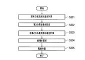
- step S301 the specific resistance calculation unit 301 reads necessary information from the storage device 311 and calculates a reference DC resistance value for each line type including a combination of the material, shape, wire diameter, and the like of the high-frequency electric wire. .
- the calculated reference DC resistance value is stored in the storage device 311.
- the reference DC resistance value for each line type may be stored in advance in the storage device 311 or may be input from the input device 312. Further, the reference DC resistance value for each line type may be actually measured instead of being calculated using a theoretical formula.
- step S302 the frequency setting unit 302 reads out a specific frequency band in which the electric wire designed from the storage device 311 is used, and the AC resistance of the electric wire and the AC resistance of the Cu wire having the same wire diameter as the electric wire.
- the set second frequency is stored in the storage device 311.
- step S3 the target resistance calculation unit 303 calculates the reference DC resistance value from the second frequency set by the frequency setting unit 302 using the formula (53) or the formula (54).
- the calculated reference DC resistance value is stored in the storage device 311. Further, the target resistance calculation unit 303 reads a specific frequency band in which the electric wire designed by the storage device 311 is used, and calculates a target reference DC resistance value so as to satisfy the relationship of Expression (55). good.
- step S304 the line type selection unit 304 determines that the reference DC resistance value calculated by the specific resistance calculation unit 301 among the plurality of line types is calculated by the target resistance calculation unit 303. Determine the line type that is greater than or equal to the value. The determined line type is stored in the storage device 311.
- step S305 an electric wire having a wire type composed of a combination of the material, shape, wire diameter, and the like determined by the wire type selecting unit 304 is manufactured.
- a central conductor 32 made of aluminum or aluminum alloy having a diameter of about 9.5 mm to 12.0 mm is prepared.
- a coating layer 33 is formed on the surface of the central conductor 32 by performing TIG welding or plasma welding or the like while applying a copper tape having a thickness of about 0.1 mm to 0.4 mm to the surface of the central conductor 32 by a vertical attachment method. Cover.
- the base conductor 32 made of the center conductor 32 covered with the covering layer 33 is manufactured by forming the center conductor 32 covered with the covering layer 33 into a diameter of about 9.3 mm to 12.3 mm using a skin pass.
- the base material is drawn by passing through a plurality of drawing dies of about 25 to 26 passes. By going through a plurality of wire drawing dies, the diameter of the electric wire is finally made the same as the determined wire diameter.
- the line is calculated from the reference resistance value calculated using the equation (53) or the equation (54).
- the species can be determined.
- the second frequency is set higher than the upper limit value of the specific frequency band in the specific frequency band in which the high-frequency electric wire is used. Therefore, the loss due to the eddy current is equal compared to the Cu wire having the same wire diameter. Therefore, it is possible to design the wire diameter of the high frequency electric wire that can reduce the AC resistance.
- ⁇ Wire design program> A series of procedures shown in FIG. 64, that is: (a) a step of calculating a direct current resistance value per unit length for each wire type composed of a combination of the material, shape, wire diameter, etc. of the high-frequency wire; The AC resistance and the AC resistance of the Cu wire having the same wire diameter as the electric wire match each other, and the AC frequency of the electric wire is smaller than the AC resistance of the Cu wire between the first frequency and the first frequency.
- the step of determining the type of the electric wire according to the direct current resistance value can be executed by controlling the electric wire designing apparatus shown in FIG. 63 by the program of the algorithm equivalent to FIG.
- This program may be stored in the storage device 311 of the computer system constituting the electric wire designing apparatus of the present invention. Further, this program can be stored in a computer-readable recording medium, and the recording medium can be read into the storage device 311 or the like, thereby executing a series of procedures according to the third embodiment of the present invention.
- “computer-readable recording medium” means a medium capable of recording a program, such as a semiconductor memory, a magnetic disk, and an optical disk.
- the main body of the electric wire design apparatus can be configured to incorporate a recording medium reader or to be externally connected. Further, it can be stored in the storage device 311 via an information processing network such as a wireless communication network.
- the high-frequency electric wire according to the fourth embodiment of the present invention is an electric wire used in a frequency band of about 10 kHz to 1 MHz, and as shown in FIG. 65, a copper alloy having a higher volume resistivity than copper is used as a conductor. This is part 41.
- the diameter of the high frequency electric wire is preferably about 0.05 mm to 0.6 mm, but is not particularly limited.
- the copper alloy layer 1 is made of, for example, brass (brass), phosphor bronze, or quartz bronze.
- Brass is an alloy (Cu—Zn) containing copper (Cu) and zinc (Zn), and may contain a small amount of elements other than copper and zinc.
- Silica bronze is an alloy (Cu—Sn—Si) containing copper, tin (Sn) and silicon (Si), and may contain a small amount of elements other than copper, tin and silicon.
- Phosphor bronze is an alloy (Cu—Sn—P) containing copper, tin and phosphorus (P), and may contain a small amount of elements other than copper, tin and phosphorus.
- the winding of a transformer, a reactor, or the like is an insulating coating of Cu wire with polyurethane, polyester, polyesterimide, polyamideimide, polyimide, or the like. Since the coaxial cable is a high-frequency current signal, the skin effect characteristic is taken into consideration, and for example, a CCA line in which a copper layer is coated on the outer side of the Al line is used.
- the diameter of the winding or the litz wire is generally used for the purpose of reducing the AC loss.
- the litz wire since it is difficult to remove the insulating film in the soldering process for connection and the number of strands increases, there is a limit to the reduction in diameter.
- the high frequency electric wire according to the fourth embodiment of the present invention even if the litz wire is not used, a further deterrent effect is imparted to the thinned wire for suppressing an increase in AC resistance. It is.
- the external magnetic field tends to avoid the high-frequency electric wire, but in a relatively low frequency band of less than about several hundred kHz, the external magnetic field cannot avoid the high-frequency electric wire and avoid high frequency. It enters the inside of the wire uniformly and induces an eddy current due to the proximity effect. At this time, it was found that the higher the electrical conductivity of the material of the high-frequency wire (that is, the smaller the volume resistivity), the more the eddy current increases, resulting in an increase in AC resistance.
- a copper alloy having a volume resistivity higher than that of copper is applied to the high-frequency electric wire.
- each volume resistivity of brass (brass), phosphor bronze, and quartz bronze is higher than copper.
- Pure aluminum also has a higher volume resistivity than copper, but the surface of Al wire is covered with an oxide film, and its removal is difficult.
- copper alloys such as brass (brass), phosphor bronze, and quartz bronze are advantageous in that such problems do not occur.
- a copper alloy having a higher volume resistivity than copper such as brass (brass), phosphor bronze, or quartz bronze is used as the conductor portion 41.
- 69 and 70 as a comparative example, the magnetic field strength distribution and the loss distribution along the y-axis of the Cu wire when the external magnetic field strength is 1 A / mm and 100 kHz is applied to the Cu wire having a radius of 0.2 mm, respectively.
- Show. 71 and 72 as a high-frequency electric wire according to the fourth embodiment of the present invention, an external magnetic field strength of 1 A / mm and a quartz bronze wire when 100 kHz is applied to a quartz bronze wire having a radius of 0.2 mm.
- FIG. 71 and FIG. 69 are compared, it can be seen that the magnetic field intensity in the vicinity of the surface layer of the quartz bronze wire is weaker than that of the Cu wire. Moreover, when FIG. 72 is compared with FIG. 70, it turns out that the loss by the eddy current of a quartz bronze wire becomes small compared with the case of Cu wire.
- the brass wire when an external magnetic field strength is 1 A / mm and 100 kHz is applied to a brass wire having a radius of 0.2 mm.
- the magnetic field strength distribution and the loss distribution along the y-axis are respectively shown. Comparing FIG. 73 with FIG. 69, it can be seen that the magnetic field intensity near the surface layer of the brass wire is weaker than that of the Cu wire. Also, comparing FIG. 74 with FIG. 70, it can be seen that the loss due to the eddy current of the brass wire is smaller than that of the Cu wire.
- FIG. 77 shows a brass wire, a phosphor bronze wire, a quartz bronze wire and a comparative example according to the fourth embodiment of the present invention calculated with an external magnetic field strength H of 1 (A / mm).
- the AC resistance (proximity effect component) of the Cu wire is shown. From FIG. 77, it can be seen that the AC resistance of the brass wire, phosphor bronze wire, and silicon bronze wire is smaller than the AC resistance of the Cu wire in a predetermined frequency band.
- ⁇ Fourth embodiment> As a fourth example, for the brass wire according to the fourth embodiment of the present invention and the Cu wire according to the comparative example, a wire having a diameter of 0.4 mm and a length of 6.6 m as shown in FIG. Using this, a 17-turn Litz wire structure was used, magnetic field generating coils for an IH cooker were produced, and a characteristic confirmation test was performed on them. The test results are shown in FIGS. A high frequency current of about 20 kHz to 60 kHz is generally used for an IH cooker, but it can be seen that the AC resistance of the brass wire is smaller than the AC resistance of the Cu wire in a frequency band including about 20 kHz to 60 kHz. .
- a copper alloy member having a volume resistivity higher than that of copper such as brass (brass), phosphor bronze, or quartz bronze having a diameter of about 9.5 mm to 12.0 mm is prepared.
- the wires have been described as the electric wires (high-frequency wires) according to the first to fourth embodiments of the present invention. It can also be used, and the AC resistance can be more effectively suppressed even in the case of collective wires or litz wires.
- equations (1) to (52) have been described as examples of theoretical formulas of the AC resistance R ac , the AC resistance R s due to the skin effect, and the AC resistance R p due to the proximity effect, but the AC resistance R ac , the skin effect
- the calculation method of the AC resistance R s due to and the AC resistance R p due to the proximity effect is not particularly limited thereto.
- the AC resistance R ac , the AC resistance R s due to the skin effect, and the AC resistance R p due to the proximity effect may be actually measured instead of being calculated using a theoretical formula.
- the high-frequency electric wires according to the first to fourth embodiments of the present invention may be used as enameled wires whose surfaces are covered with an insulating coating layer such as polyurethane.
- the electric wire of the present invention includes a high-frequency transformer, a motor, a reactor, a choke coil, an induction heating device, a magnetic head, a high-frequency power supply cable, a DC power supply unit, a switching power supply, an AC adapter, an eddy current detection type displacement sensor / flaw detection sensor,
- the present invention can be used in the electronic equipment industry including the manufacturing industry of various devices such as IH cooking heaters, non-contact power feeding devices, and high-frequency current generators.
Landscapes
- Engineering & Computer Science (AREA)
- Power Engineering (AREA)
- Physics & Mathematics (AREA)
- Theoretical Computer Science (AREA)
- Evolutionary Computation (AREA)
- Geometry (AREA)
- General Engineering & Computer Science (AREA)
- General Physics & Mathematics (AREA)
- Computer Hardware Design (AREA)
- Insulated Conductors (AREA)
- Windings For Motors And Generators (AREA)
- Non-Insulated Conductors (AREA)
- Architecture (AREA)
- Software Systems (AREA)
- Coils Of Transformers For General Uses (AREA)
- Induction Machinery (AREA)
- Insulation, Fastening Of Motor, Generator Windings (AREA)
Priority Applications (9)
| Application Number | Priority Date | Filing Date | Title |
|---|---|---|---|
| KR1020137006940A KR101284074B1 (ko) | 2010-08-20 | 2011-07-21 | 전선, 코일, 전선의 설계 장치 및 전기 모터 |
| CN201180040420.7A CN103098144B (zh) | 2010-08-20 | 2011-07-21 | 电线、线圈、电线的设计装置及电动机 |
| JP2011550162A JP5061259B2 (ja) | 2010-08-20 | 2011-07-21 | 電線及びコイル |
| KR1020137010312A KR101284075B1 (ko) | 2010-08-20 | 2011-07-21 | 전선, 코일, 전선의 설계 장치 및 전기 모터 |
| EP11818022.3A EP2608222B1 (en) | 2010-08-20 | 2011-07-21 | Method of manufacturing a high-frequency electric wire |
| BR112013003939A BR112013003939A2 (pt) | 2010-08-20 | 2011-07-21 | fio elétrico, bobina, aparelho para projetar fio elétrico, e motor elétrico |
| US13/770,445 US8866019B2 (en) | 2010-08-20 | 2013-02-19 | Electric wire, coil, device for designing electric wire, and electric motor |
| US13/874,852 US8723387B2 (en) | 2010-08-20 | 2013-05-01 | Electric wire, coil, device for designing electric wire, and electric motor |
| US14/290,444 US9425662B2 (en) | 2010-08-20 | 2014-05-29 | Electric wire, coil, device for designing electric wire, and electric motor |
Applications Claiming Priority (12)
| Application Number | Priority Date | Filing Date | Title |
|---|---|---|---|
| JP2010-185638 | 2010-08-20 | ||
| JP2010185635 | 2010-08-20 | ||
| JP2010-185635 | 2010-08-20 | ||
| JP2010185638 | 2010-08-20 | ||
| JP2010185636 | 2010-08-20 | ||
| JP2010-185637 | 2010-08-20 | ||
| JP2010185637 | 2010-08-20 | ||
| JP2010-185636 | 2010-08-20 | ||
| JP2010209651 | 2010-09-17 | ||
| JP2010-209651 | 2010-09-17 | ||
| JP2010-283809 | 2010-12-20 | ||
| JP2010283809 | 2010-12-20 |
Related Child Applications (3)
| Application Number | Title | Priority Date | Filing Date |
|---|---|---|---|
| US13770445 A-371-Of-International | 2011-07-21 | ||
| US13/770,445 Continuation US8866019B2 (en) | 2010-08-20 | 2013-02-19 | Electric wire, coil, device for designing electric wire, and electric motor |
| US14/290,444 Division US9425662B2 (en) | 2010-08-20 | 2014-05-29 | Electric wire, coil, device for designing electric wire, and electric motor |
Publications (1)
| Publication Number | Publication Date |
|---|---|
| WO2012023378A1 true WO2012023378A1 (ja) | 2012-02-23 |
Family
ID=45605039
Family Applications (1)
| Application Number | Title | Priority Date | Filing Date |
|---|---|---|---|
| PCT/JP2011/066563 Ceased WO2012023378A1 (ja) | 2010-08-20 | 2011-07-21 | 電線、コイル、電線の設計装置及び電気モータ |
Country Status (7)
| Country | Link |
|---|---|
| US (3) | US8866019B2 (enExample) |
| EP (2) | EP2608222B1 (enExample) |
| JP (4) | JP5061259B2 (enExample) |
| KR (2) | KR101284074B1 (enExample) |
| CN (2) | CN103098144B (enExample) |
| BR (1) | BR112013003939A2 (enExample) |
| WO (1) | WO2012023378A1 (enExample) |
Cited By (5)
| Publication number | Priority date | Publication date | Assignee | Title |
|---|---|---|---|---|
| JP2012151127A (ja) * | 2010-08-20 | 2012-08-09 | Fujikura Ltd | 電線の製造方法及び電線の設計方法 |
| WO2013051665A1 (ja) * | 2011-10-05 | 2013-04-11 | 矢崎総業株式会社 | 交流電線の仕様決定支援方法および仕様決定支援装置ならびに仕様決定支援プログラム |
| WO2014148430A1 (ja) | 2013-03-18 | 2014-09-25 | 株式会社フジクラ | 電線及びコイル |
| WO2015083456A1 (ja) | 2013-12-02 | 2015-06-11 | 株式会社フジクラ | 高周波用電線およびコイル |
| CN105428158A (zh) * | 2015-10-31 | 2016-03-23 | 成都海沃斯电气技术有限公司 | 交流接触器励磁线圈及其驱动机构 |
Families Citing this family (20)
| Publication number | Priority date | Publication date | Assignee | Title |
|---|---|---|---|---|
| DE102009061032A1 (de) * | 2009-05-15 | 2010-11-18 | Tyco Electronics Belgium Ec Bvba | Magnetoelektronischer Winkelsensor, insbesondere Reluktanzresolver |
| EP3082135B1 (en) * | 2011-09-22 | 2018-05-02 | Fujikura Ltd. | Electric wire and coil |
| CN203078469U (zh) * | 2012-01-20 | 2013-07-24 | 德昌电机(深圳)有限公司 | 安全带舌板驱动器 |
| CN104283351A (zh) * | 2013-07-02 | 2015-01-14 | 丹佛斯(天津)有限公司 | 定子、三相感应电机和压缩机 |
| US20150061441A1 (en) * | 2013-08-29 | 2015-03-05 | Regal Beloit America, Inc. | Electric machine and associated method |
| US20160099622A1 (en) * | 2014-10-07 | 2016-04-07 | Hamilton Sundstrand Corporation | Hybrid Conductor for Generator Stator Winding |
| US20170163141A1 (en) * | 2015-12-08 | 2017-06-08 | Mary Fales | System, method, and apparatus for energy recapture using induction |
| US10776552B2 (en) * | 2016-12-05 | 2020-09-15 | Synopsys, Inc. | Nano-wire resistance model |
| CN106705827B (zh) * | 2017-02-23 | 2019-03-12 | 苏州热工研究院有限公司 | 一种涡流探头线圈中导线最优直径的计算方法 |
| US10685163B2 (en) | 2017-03-01 | 2020-06-16 | Synopsys, Inc. | Computationally efficient nano-scale conductor resistance model |
| DE102017211547A1 (de) * | 2017-07-06 | 2019-01-10 | Siemens Aktiengesellschaft | Modularer Mehrpegelenergiewandler |
| CN107798184B (zh) * | 2017-10-19 | 2021-04-02 | 武汉科技大学 | 一种采空区临界大冒落跨度及时间的确定方法 |
| EP3713050B1 (en) * | 2019-03-22 | 2022-05-25 | ABB Schweiz AG | Induction motor |
| WO2020252242A1 (en) | 2019-06-12 | 2020-12-17 | Phosphorus Free Water Solutions, Llc | Removal of materials from water |
| US12351492B2 (en) | 2019-06-12 | 2025-07-08 | Nuquatic, Llc | Removal of materials from water |
| US11401181B1 (en) | 2021-03-02 | 2022-08-02 | Phosphorus Free Water Solutions, Llc | Galvanic process for treating aqueous compositions |
| US20240364166A1 (en) * | 2022-06-15 | 2024-10-31 | Joby Aero, Inc. | Solid Motor Coils And Motors Using Same |
| CN121263383A (zh) | 2023-04-05 | 2026-01-02 | 努夸蒂克有限责任公司 | 具有金属组分的水性组合物的处理 |
| US12122691B1 (en) | 2023-04-05 | 2024-10-22 | Nuquatic, Llc | Removal of fluoroalkyl compounds from water using galvanic cell |
| WO2025253168A1 (en) * | 2024-06-03 | 2025-12-11 | Ceme S.P.A. | Cca wire coil |
Citations (7)
| Publication number | Priority date | Publication date | Assignee | Title |
|---|---|---|---|---|
| JPS6276216A (ja) * | 1985-09-30 | 1987-04-08 | 株式会社フジクラ | 高周波電線 |
| JP2001280249A (ja) * | 2000-03-31 | 2001-10-10 | Matsushita Electric Ind Co Ltd | 圧縮機および電動機 |
| JP2002358840A (ja) * | 2001-05-31 | 2002-12-13 | Totoku Electric Co Ltd | 高周波コイル用平編みリッツ線 |
| JP2008148533A (ja) * | 2006-12-13 | 2008-06-26 | Nidec Shibaura Corp | モータ |
| WO2009004989A1 (ja) * | 2007-06-29 | 2009-01-08 | Tokyo Institute Of Technology | 高周波用配線材料 |
| JP2009129654A (ja) * | 2007-11-22 | 2009-06-11 | Totoku Electric Co Ltd | 複合電線およびコイル |
| JP2010093145A (ja) * | 2008-10-10 | 2010-04-22 | Totoku Electric Co Ltd | アルファ巻きコイル |
Family Cites Families (26)
| Publication number | Priority date | Publication date | Assignee | Title |
|---|---|---|---|---|
| US2107177A (en) * | 1934-11-01 | 1938-02-01 | Bell Telephone Labor Inc | Stranded conductor |
| DE2927796C2 (de) * | 1979-07-10 | 1982-03-25 | Weiß, Paul, Prof. Dr.-Ing., 6791 Queidersbach | Stromleiter |
| US5438997A (en) * | 1991-03-13 | 1995-08-08 | Sieben; Wayne | Intravascular imaging apparatus and methods for use and manufacture |
| JP3083396B2 (ja) * | 1992-03-06 | 2000-09-04 | 住友電気工業株式会社 | 直流用高圧電線 |
| US5574260B1 (en) * | 1995-03-06 | 2000-01-18 | Gore & Ass | Composite conductor having improved high frequency signal transmission characteristics |
| WO1996042089A1 (en) * | 1995-06-08 | 1996-12-27 | Weijun Yin | Pulsed voltage surge resistant magnet wire |
| US5861578A (en) * | 1997-01-27 | 1999-01-19 | Rea Magnet Wire Company, Inc. | Electrical conductors coated with corona resistant, multilayer insulation system |
| FR2771859B1 (fr) * | 1997-11-28 | 1999-12-31 | Telecommunications Sa | Cable rayonnant |
| US6758430B1 (en) * | 1999-02-16 | 2004-07-06 | Aesop, Inc. | Method of winding motors and other electric machines to reduce AC losses |
| JP4000729B2 (ja) * | 1999-12-15 | 2007-10-31 | 日立電線株式会社 | 同軸ケーブル及びその製造方法 |
| JP2002150633A (ja) | 2000-11-07 | 2002-05-24 | Matsushita Electric Ind Co Ltd | 磁気ヘッド装置 |
| WO2003069762A1 (fr) * | 2002-02-09 | 2003-08-21 | Youguo Huang | Moteur asynchrone a induction a configuration de commutation |
| CN100376072C (zh) * | 2002-04-15 | 2008-03-19 | 乐金电子(天津)电器有限公司 | 鼠笼式感应电机的转子 |
| JP2005108654A (ja) | 2003-09-30 | 2005-04-21 | Canon Inc | リッツ線、それを用いた励磁コイルおよび誘導加熱装置 |
| JP4126035B2 (ja) | 2004-07-30 | 2008-07-30 | 岩井機械工業株式会社 | 弁体構造 |
| WO2006046358A1 (ja) * | 2004-10-28 | 2006-05-04 | Shinshu University | 高周波コイルを備えた機器 |
| US7544886B2 (en) * | 2005-12-20 | 2009-06-09 | Hitachi Cable, Ltd. | Extra-fine copper alloy wire, extra-fine copper alloy twisted wire, extra-fine insulated wire, coaxial cable, multicore cable and manufacturing method thereof |
| JP2008166141A (ja) * | 2006-12-28 | 2008-07-17 | Auto Network Gijutsu Kenkyusho:Kk | 電線導体および絶縁電線 |
| EP2219193A4 (en) * | 2007-11-01 | 2012-07-04 | Furukawa Electric Co Ltd | LADDER MATERIAL FOR AN ELECTRONIC ARRANGEMENT AND ELECTRICAL WIRING FOR WIRING USING THEREOF |
| JP2009129550A (ja) | 2007-11-20 | 2009-06-11 | Totoku Electric Co Ltd | クラッド電線、リッツ線、集合線およびコイル |
| WO2009066874A2 (en) * | 2007-11-22 | 2009-05-28 | Lg Electronics Inc. | Motor for compressor and hermetic compressor having the same |
| US8441165B2 (en) * | 2007-11-22 | 2013-05-14 | Lg Electronics Inc. | Motor for compressor and hermetic compressor having the same |
| US20110198118A1 (en) * | 2010-02-17 | 2011-08-18 | Ta Ya Electric Wire & Cable Co., Ltd. | Magnet wire |
| WO2011118054A1 (ja) * | 2010-03-23 | 2011-09-29 | 株式会社フジクラ | 高周波電線及び高周波コイル |
| KR101284074B1 (ko) * | 2010-08-20 | 2013-07-10 | 가부시키가이샤후지쿠라 | 전선, 코일, 전선의 설계 장치 및 전기 모터 |
| EP3082135B1 (en) * | 2011-09-22 | 2018-05-02 | Fujikura Ltd. | Electric wire and coil |
-
2011
- 2011-07-21 KR KR1020137006940A patent/KR101284074B1/ko not_active Expired - Fee Related
- 2011-07-21 CN CN201180040420.7A patent/CN103098144B/zh not_active Expired - Fee Related
- 2011-07-21 EP EP11818022.3A patent/EP2608222B1/en not_active Not-in-force
- 2011-07-21 EP EP13163890.0A patent/EP2621057B1/en not_active Not-in-force
- 2011-07-21 WO PCT/JP2011/066563 patent/WO2012023378A1/ja not_active Ceased
- 2011-07-21 KR KR1020137010312A patent/KR101284075B1/ko not_active Expired - Fee Related
- 2011-07-21 CN CN201310125619.0A patent/CN103236752B/zh not_active Expired - Fee Related
- 2011-07-21 JP JP2011550162A patent/JP5061259B2/ja not_active Expired - Fee Related
- 2011-07-21 BR BR112013003939A patent/BR112013003939A2/pt active Search and Examination
-
2012
- 2012-04-23 JP JP2012098087A patent/JP5135481B2/ja not_active Expired - Fee Related
- 2012-04-23 JP JP2012098092A patent/JP5162712B2/ja not_active Expired - Fee Related
- 2012-04-23 JP JP2012098030A patent/JP2012169288A/ja active Pending
-
2013
- 2013-02-19 US US13/770,445 patent/US8866019B2/en not_active Expired - Fee Related
- 2013-05-01 US US13/874,852 patent/US8723387B2/en not_active Expired - Fee Related
-
2014
- 2014-05-29 US US14/290,444 patent/US9425662B2/en not_active Expired - Fee Related
Patent Citations (7)
| Publication number | Priority date | Publication date | Assignee | Title |
|---|---|---|---|---|
| JPS6276216A (ja) * | 1985-09-30 | 1987-04-08 | 株式会社フジクラ | 高周波電線 |
| JP2001280249A (ja) * | 2000-03-31 | 2001-10-10 | Matsushita Electric Ind Co Ltd | 圧縮機および電動機 |
| JP2002358840A (ja) * | 2001-05-31 | 2002-12-13 | Totoku Electric Co Ltd | 高周波コイル用平編みリッツ線 |
| JP2008148533A (ja) * | 2006-12-13 | 2008-06-26 | Nidec Shibaura Corp | モータ |
| WO2009004989A1 (ja) * | 2007-06-29 | 2009-01-08 | Tokyo Institute Of Technology | 高周波用配線材料 |
| JP2009129654A (ja) * | 2007-11-22 | 2009-06-11 | Totoku Electric Co Ltd | 複合電線およびコイル |
| JP2010093145A (ja) * | 2008-10-10 | 2010-04-22 | Totoku Electric Co Ltd | アルファ巻きコイル |
Cited By (12)
| Publication number | Priority date | Publication date | Assignee | Title |
|---|---|---|---|---|
| JP2012151127A (ja) * | 2010-08-20 | 2012-08-09 | Fujikura Ltd | 電線の製造方法及び電線の設計方法 |
| JP2012169288A (ja) * | 2010-08-20 | 2012-09-06 | Fujikura Ltd | 電線及びコイル |
| WO2013051665A1 (ja) * | 2011-10-05 | 2013-04-11 | 矢崎総業株式会社 | 交流電線の仕様決定支援方法および仕様決定支援装置ならびに仕様決定支援プログラム |
| WO2014148430A1 (ja) | 2013-03-18 | 2014-09-25 | 株式会社フジクラ | 電線及びコイル |
| CN105051833A (zh) * | 2013-03-18 | 2015-11-11 | 株式会社藤仓 | 电线及线圈 |
| EP2977994A4 (en) * | 2013-03-18 | 2017-01-11 | Fujikura Ltd. | Wire and coil |
| JP6062035B2 (ja) * | 2013-03-18 | 2017-01-18 | 株式会社フジクラ | 電線及びコイル |
| CN105051833B (zh) * | 2013-03-18 | 2017-03-15 | 株式会社藤仓 | 电线及线圈 |
| US9859032B2 (en) | 2013-03-18 | 2018-01-02 | Fujikura Ltd. | Electric wire for reducing AC resistance to be equal to or less than copper wire |
| WO2015083456A1 (ja) | 2013-12-02 | 2015-06-11 | 株式会社フジクラ | 高周波用電線およびコイル |
| KR20160065959A (ko) | 2013-12-02 | 2016-06-09 | 가부시키가이샤후지쿠라 | 고주파용 전선 및 코일 |
| CN105428158A (zh) * | 2015-10-31 | 2016-03-23 | 成都海沃斯电气技术有限公司 | 交流接触器励磁线圈及其驱动机构 |
Also Published As
| Publication number | Publication date |
|---|---|
| EP2608222B1 (en) | 2018-12-05 |
| EP2608222A1 (en) | 2013-06-26 |
| JP2012147670A (ja) | 2012-08-02 |
| US8866019B2 (en) | 2014-10-21 |
| EP2621057A2 (en) | 2013-07-31 |
| CN103236752A (zh) | 2013-08-07 |
| EP2621057A3 (en) | 2016-01-20 |
| CN103098144B (zh) | 2015-08-05 |
| JP5135481B2 (ja) | 2013-02-06 |
| JP5162712B2 (ja) | 2013-03-13 |
| JP5061259B2 (ja) | 2012-10-31 |
| JPWO2012023378A1 (ja) | 2013-10-28 |
| US8723387B2 (en) | 2014-05-13 |
| CN103098144A (zh) | 2013-05-08 |
| EP2621057B1 (en) | 2017-11-01 |
| KR101284075B1 (ko) | 2013-07-10 |
| JP2012151127A (ja) | 2012-08-09 |
| JP2012169288A (ja) | 2012-09-06 |
| EP2608222A4 (en) | 2015-12-23 |
| CN103236752B (zh) | 2014-11-26 |
| BR112013003939A2 (pt) | 2016-07-12 |
| KR20130050976A (ko) | 2013-05-16 |
| US9425662B2 (en) | 2016-08-23 |
| KR20130054444A (ko) | 2013-05-24 |
| US20140265713A1 (en) | 2014-09-18 |
| US20130162097A1 (en) | 2013-06-27 |
| KR101284074B1 (ko) | 2013-07-10 |
| US20130234637A1 (en) | 2013-09-12 |
Similar Documents
| Publication | Publication Date | Title |
|---|---|---|
| JP5061259B2 (ja) | 電線及びコイル | |
| JP5266340B2 (ja) | 高周波電線及び高周波コイル | |
| JP5407004B2 (ja) | 電線及びコイル | |
| JP5957428B2 (ja) | 高周波電線およびその製造方法 | |
| JP2012147670A5 (enExample) | ||
| JP6194369B2 (ja) | 高周波用電線およびコイル | |
| JP2012151127A5 (enExample) | ||
| JP6062035B2 (ja) | 電線及びコイル | |
| JP2017130613A (ja) | コイル装置 |
Legal Events
| Date | Code | Title | Description |
|---|---|---|---|
| WWE | Wipo information: entry into national phase |
Ref document number: 201180040420.7 Country of ref document: CN |
|
| WWE | Wipo information: entry into national phase |
Ref document number: 2011550162 Country of ref document: JP |
|
| 121 | Ep: the epo has been informed by wipo that ep was designated in this application |
Ref document number: 11818022 Country of ref document: EP Kind code of ref document: A1 |
|
| NENP | Non-entry into the national phase |
Ref country code: DE |
|
| WWE | Wipo information: entry into national phase |
Ref document number: 2011818022 Country of ref document: EP |
|
| ENP | Entry into the national phase |
Ref document number: 20137006940 Country of ref document: KR Kind code of ref document: A |
|
| REG | Reference to national code |
Ref country code: BR Ref legal event code: B01A Ref document number: 112013003939 Country of ref document: BR |
|
| ENP | Entry into the national phase |
Ref document number: 112013003939 Country of ref document: BR Kind code of ref document: A2 Effective date: 20130220 |