WO2012023378A1 - Electric wire, coil, device for designing electric wire, and electric motor - Google Patents
Electric wire, coil, device for designing electric wire, and electric motor Download PDFInfo
- Publication number
- WO2012023378A1 WO2012023378A1 PCT/JP2011/066563 JP2011066563W WO2012023378A1 WO 2012023378 A1 WO2012023378 A1 WO 2012023378A1 JP 2011066563 W JP2011066563 W JP 2011066563W WO 2012023378 A1 WO2012023378 A1 WO 2012023378A1
- Authority
- WO
- WIPO (PCT)
- Prior art keywords
- wire
- resistance
- frequency
- electric wire
- copper
- Prior art date
Links
Images


Classifications
-
- H—ELECTRICITY
- H02—GENERATION; CONVERSION OR DISTRIBUTION OF ELECTRIC POWER
- H02K—DYNAMO-ELECTRIC MACHINES
- H02K3/00—Details of windings
-
- G—PHYSICS
- G06—COMPUTING; CALCULATING OR COUNTING
- G06F—ELECTRIC DIGITAL DATA PROCESSING
- G06F30/00—Computer-aided design [CAD]
-
- H—ELECTRICITY
- H01—ELECTRIC ELEMENTS
- H01B—CABLES; CONDUCTORS; INSULATORS; SELECTION OF MATERIALS FOR THEIR CONDUCTIVE, INSULATING OR DIELECTRIC PROPERTIES
- H01B1/00—Conductors or conductive bodies characterised by the conductive materials; Selection of materials as conductors
- H01B1/02—Conductors or conductive bodies characterised by the conductive materials; Selection of materials as conductors mainly consisting of metals or alloys
- H01B1/023—Alloys based on aluminium
-
- H—ELECTRICITY
- H01—ELECTRIC ELEMENTS
- H01B—CABLES; CONDUCTORS; INSULATORS; SELECTION OF MATERIALS FOR THEIR CONDUCTIVE, INSULATING OR DIELECTRIC PROPERTIES
- H01B1/00—Conductors or conductive bodies characterised by the conductive materials; Selection of materials as conductors
- H01B1/02—Conductors or conductive bodies characterised by the conductive materials; Selection of materials as conductors mainly consisting of metals or alloys
- H01B1/026—Alloys based on copper
-
- H—ELECTRICITY
- H02—GENERATION; CONVERSION OR DISTRIBUTION OF ELECTRIC POWER
- H02K—DYNAMO-ELECTRIC MACHINES
- H02K3/00—Details of windings
- H02K3/02—Windings characterised by the conductor material
-
- H—ELECTRICITY
- H02—GENERATION; CONVERSION OR DISTRIBUTION OF ELECTRIC POWER
- H02K—DYNAMO-ELECTRIC MACHINES
- H02K3/00—Details of windings
- H02K3/04—Windings characterised by the conductor shape, form or construction, e.g. with bar conductors
-
- H—ELECTRICITY
- H01—ELECTRIC ELEMENTS
- H01B—CABLES; CONDUCTORS; INSULATORS; SELECTION OF MATERIALS FOR THEIR CONDUCTIVE, INSULATING OR DIELECTRIC PROPERTIES
- H01B7/00—Insulated conductors or cables characterised by their form
- H01B7/30—Insulated conductors or cables characterised by their form with arrangements for reducing conductor losses when carrying alternating current, e.g. due to skin effect
-
- H—ELECTRICITY
- H01—ELECTRIC ELEMENTS
- H01F—MAGNETS; INDUCTANCES; TRANSFORMERS; SELECTION OF MATERIALS FOR THEIR MAGNETIC PROPERTIES
- H01F5/00—Coils
-
- Y—GENERAL TAGGING OF NEW TECHNOLOGICAL DEVELOPMENTS; GENERAL TAGGING OF CROSS-SECTIONAL TECHNOLOGIES SPANNING OVER SEVERAL SECTIONS OF THE IPC; TECHNICAL SUBJECTS COVERED BY FORMER USPC CROSS-REFERENCE ART COLLECTIONS [XRACs] AND DIGESTS
- Y02—TECHNOLOGIES OR APPLICATIONS FOR MITIGATION OR ADAPTATION AGAINST CLIMATE CHANGE
- Y02T—CLIMATE CHANGE MITIGATION TECHNOLOGIES RELATED TO TRANSPORTATION
- Y02T10/00—Road transport of goods or passengers
- Y02T10/80—Technologies aiming to reduce greenhouse gasses emissions common to all road transportation technologies
- Y02T10/82—Elements for improving aerodynamics
Definitions
- the present invention relates to an electric wire, a coil, an electric wire design device, and an electric motor.
- CCA wire copper-coated aluminum wire
- Al wire aluminum wire
- Cu wires copper-coated copper wire
- JP 2009-129550 A Japanese Unexamined Patent Publication No. Sho 62-76216 JP 2005-108654 A International Publication No. 2006/046358 JP 2002-150633 A
- an object of the present invention is to provide an electric wire, coil, and electric wire design device that can reduce or reduce an AC resistance by making loss due to an eddy current equal to or smaller than a reference Cu wire. And providing an electric motor.
- an electric wire including a conductor portion made of a material having a higher volume resistivity than copper, and in the frequency band in which the electric wire is used, the conductor portion with respect to an AC resistance of a reference Cu wire
- An electric wire is provided in which the volume resistivity of the conductor is defined so that the ratio of the AC resistance is less than 1.
- the reference Cu wire may have the same wire diameter as the conductor portion.
- the AC resistance of the electric wire and the AC resistance of the Cu wire as a reference match each other, and the AC resistance of the electric wire between each other is smaller than the AC resistance of the Cu wire as a reference.
- a direct current resistance value per length may be defined.
- the DC resistance value is defined as Rdc as the DC resistance value and f2 as the second frequency.
- Rdc the DC resistance value
- f2 the second frequency.
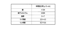
- the conductor portion may be made of any one of brass, phosphor bronze, silica bronze, a copper alloy selected from a copper / beryllium alloy and a copper / nickel / silicon alloy, and copper-coated aluminum.
- the frequency band in which the electric wire is used may include harmonic frequencies from the reference frequency to the 20th order.
- the frequency band in which the electric wire is used may be 10 kHz to 1 MHz.
- a coil using an electric wire as a strand includes a conductor portion made of a material having a higher volume resistivity than copper, and in a frequency band in which the electric wire is used, a reference A coil is provided in which the volume resistivity of the conductor is defined such that the ratio of the AC resistance of the conductor to the AC resistance of the Cu wire is less than 1.
- the reference Cu wire may have the same wire diameter as the conductor portion.
- the AC resistance of the electric wire and the AC resistance of the Cu wire used as a reference coincide with each other, and the AC resistance of the electric wire between them is smaller than the AC resistance of the Cu wire used as a reference.
- the volume resistivity of the conductor portion is divided by the cross-sectional area so that the second frequency is equal to or higher than the upper limit value of the frequency band in which the electric wire is used among the first frequency and the second frequency larger than the first frequency.
- a DC resistance value per unit length may be defined.
- the DC resistance value is defined as Rdc as the DC resistance value and f2 as the second frequency.
- Rdc the DC resistance value
- f2 the second frequency.
- the conductor portion may be composed of any one of brass, phosphor bronze, quartz bronze, a copper alloy selected from a copper / beryllium alloy and a copper / nickel / silicon alloy, and copper-coated aluminum. .
- the frequency band in which the wire is used may include harmonic frequencies from the reference frequency to the 20th order.
- the frequency band in which the electric wire is used may be 10 kHz to 1 MHz.
- an electric wire design device made of a material having a volume resistivity higher than that of copper, the AC resistance of a conductor part that is a candidate for an electric wire in a frequency band in which the electric wire is used, and A ratio calculator for calculating the AC resistance of the reference Cu wire, a ratio calculator for calculating the ratio of the AC resistance due to the proximity effect of the conductor to the AC resistance due to the proximity effect of the reference Cu wire, and a ratio of 1
- an electric wire design apparatus provided with the determination part which determines that a candidate is applicable to an electric wire is provided.
- a plurality of iron cores arranged in a circular shape, a central conductor made of Al wire or aluminum or an aluminum alloy, and a coating layer made of copper covering the central conductor are provided.
- the coil includes a plurality of coils wound around a plurality of iron cores, and a rotor that rotates by applying an alternating current to the plurality of coils, and the AC resistance of the coil is an alternating current of a coil wound with a reference Cu wire.
- An electric motor is provided in which the frequency of an alternating current applied to a coil is controlled by an inverter method so as to fall between a first frequency that is smaller than a resistance and a second frequency that is higher than the first frequency.
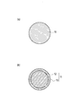
- FIG.1 (a) is sectional drawing which shows an example of the electric wire which concerns on the 1st Embodiment of this invention.
- FIG.1 (b) is sectional drawing which shows another example of the electric wire which concerns on the 1st Embodiment of this invention.
- It is a schematic diagram for demonstrating the skin effect which concerns on the 1st Embodiment of this invention.
- It is sectional drawing of the conducting wire of 2 layer structure. It is the schematic which shows the electromagnetic field of the conducting wire surface where the electric current is flowing.
- FIG. 58A is a cross-sectional view showing an example of an electric wire according to the third embodiment of the present invention.
- FIG. 58B is a cross-sectional view showing another example of the electric wire according to the third embodiment of the present invention.
- the electric wire according to the first embodiment of the present invention is an electric wire used in a specific frequency band and is made of a material having a higher volume resistivity than copper. 11.
- the ratio of the AC resistance due to the proximity effect of the conductor portion 11 to the AC resistance due to the proximity effect of the Cu wire as a reference in a specific frequency band is less than 1.
- the volume resistivity of the conductor portion 11 is defined.
- specific frequency band means a frequency band defined (set) as a range in which the electric wire (product) is used.
- the upper limit value, lower limit value, and range of the “specific frequency band” are appropriately set according to the specifications of each product, and are not particularly limited.
- the “specific frequency band” may be, for example, about several kHz to 100 kHz, or about 10 kHz to 1 MHz. In the case of an IH cooker, it may be about 20 kHz to 60 kHz. As long as the product uses the commercial power frequency of Japan, the United States, and Europe as it is, it may be about 50 kHz to 60 kHz.
- the “reference Cu wire” is defined (set) in advance, and may have the same or different wire diameter as the conductor portion 11.
- the diameter of the conductor 11 is preferably about 0.05 mm to 0.6 mm, but is not particularly limited.
- copper alloys such as brass, phosphor bronze, quartz bronze, copper / beryllium alloy, and copper / nickel / silicon alloy
- Brass is an alloy (Cu—Zn) containing copper (Cu) and zinc (Zn), and may contain a small amount of elements other than copper and zinc.
- Silica bronze is an alloy (Cu—Sn—Si) containing copper, tin (Sn) and silicon (Si), and may contain a small amount of elements other than copper, tin and silicon.
- Phosphor bronze is an alloy (Cu—Sn—P) containing copper, tin and phosphorus (P), and may contain a small amount of elements other than copper, tin and phosphorus.
- These copper alloy wires are, for example, one-principle annealed and may be plated with tin, copper, chromium (Cr), or the like.
- the conductor part 11 may have various shapes, such as flat shape other than cylindrical shape.
- the electric wire according to the first embodiment of the present invention includes a central conductor 12 made of aluminum (Al) or an aluminum alloy, and copper (Cu) covering the central conductor 12.
- the CCA line provided with the coating layer 13 made of may be used as the conductor portion 11.
- the diameter of the entire CCA line is preferably about 0.05 mm to 0.6 mm.
- the cross-sectional area of the covering layer 13 is 15% or less with respect to the cross-sectional area of the entire electric wire including the central conductor 12 and the covering layer 13, preferably about 3% to 15%, more preferably about 3% to 10%. More desirably, it is about 3% to 5%.
- the AC resistance can be reduced as the ratio of the cross-sectional area of the covering layer 13 to the entire electric wire is smaller.
- the center conductor 12 for example, an aluminum alloy of electrical aluminum (EC aluminum) or an Al—Mg—Si based alloy (JIS 6000 series) can be used.
- the aluminum alloy has a larger volume resistivity than EC aluminum. Therefore it is more desirable.
- the winding of a transformer, a reactor, or the like is an insulating coating of Cu wire with polyurethane, polyester, polyesterimide, polyamideimide, polyimide, or the like.
- the coaxial cable is a high-frequency current signal, for example, a CCA line is used in consideration of the skin effect characteristics.
- the AC resistance R ac is expressed by the following equation (1), where the DC resistance component is R dc , the AC resistance due to the skin effect is R s , and the AC resistance due to the proximity effect (proximity effect component) is R p .
- k s represents the skin effect coefficient
- each electromagnetic field uses a complex expression, and the time factor is ej ⁇ t .
- ⁇ represents an angular frequency.
- the electric current generates a z-direction component E z of the electric field, which satisfies the following wave equation (2).
- ⁇ 0 represents the magnetic permeability in vacuum.
- the magnetic field H ⁇ has only a ⁇ direction component and is given as follows.
- J ⁇ (z) represents the first kind Bessel function
- the power flow flowing into the conducting wire shown in FIG. 6 is calculated by the following equation (15) from the Poynting vector.
- Equation (18) becomes
- the magnetic potential satisfies the following wave equation (25).
- ⁇ 0 represents the magnetic permeability in vacuum.
- Equation (25) The solution of equation (25) can be set as follows.
- the magnetic field H ⁇ is obtained as follows.
- the loss P L of the conducting wire is obtained as follows.
- Equation (43) becomes the following Equation (46).
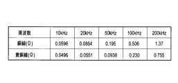
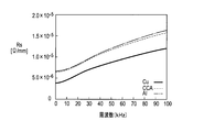
- the proximity effect when the external magnetic field intensity H of the brass wire, phosphor bronze wire, quartz bronze wire and Cu wire according to the comparative example according to the first embodiment of the present invention is 1 (A / mm).
- FIG. 9 shows that the AC resistance of the brass wire, phosphor bronze wire, and silicon bronze wire is smaller than the AC resistance of the Cu wire in a predetermined frequency band.
- the AC resistance when the external magnetic field strength H of the brass wire having a wire diameter of 0.4 mm and the Cu wire as a comparative example is 1 A / mm is expressed by the above-described equations (1), (18) and (48).
- the brass wire has a smaller AC resistance than the Cu wire having the same wire diameter in the frequency band defined between the first frequency f1 and the second frequency f2. That is, on the lower frequency side than the first frequency f1, the AC resistance of the brass wire is larger than the AC resistance of the Cu wire.
- the AC resistance of the brass wire matches the AC resistance of the Cu wire, and eddy current loss becomes dominant on the higher frequency side than the first frequency f1, so the AC resistance of the brass wire and Cu
- the magnitude of the AC resistance of the line is reversed.
- the AC resistance of the Cu wire is larger than the AC resistance of the brass wire.
- the AC resistance of the brass wire again coincides with the AC resistance of the Cu wire, and on the higher frequency side than the second frequency f2, the influence of the proximity effect of the brass wire becomes larger than that of the Cu wire, and brass.
- the magnitudes of the AC resistance of the wire and the AC resistance of the Cu wire are reversed.
- FIG. 14 shows the calculation result of the sum of the skin effect component R s and the DC resistance R dc and the proximity effect component R p when the external magnetic field strength H is 1 A / mm for a brass wire having a diameter of 0.4 mm.
- the direct current resistance R dc is a value when the frequency is 0 in the equation (1).
- FIG. 9 and FIG. 11 to FIG. 13 although the brass wire has a higher volume resistivity than copper, the reason why the AC resistance is lower than that of the Cu wire in a predetermined frequency band is shown in FIG. This is because the AC resistance greatly depends on the proximity effect as shown in FIG. 14 and there is a frequency band in which the proximity effect becomes small when the volume resistivity is high.
- the skin effect component R s and the proximity effect component R p have a frequency dependency, but if the frequency is less than 1 MHz, the proximity effect component R p is more dependent on the skin effect component R s than the skin effect component R s.
- the effect component R s is at a negligible level.
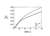
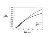
- FIG. 15 shows the ratio (Rp ratio) between the AC resistance due to the proximity effect at 100 kHz and the external magnetic field strength H of 1 A / mm and the AC resistance due to the proximity effect of the Cu wire as a reference (Rp ratio) for each conductor material. 48) shows the calculation result.
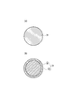
- the conductor portion 11 shown in FIG. 1A is made of pure aluminum
- the center conductor 12 shown in FIG. 1B is made of aluminum
- the cross-sectional area of the covering layer 13 is the entire wire. 1% (5% CCA), the central conductor 12 shown in FIG.
- the cross-sectional area of the covering layer 13 is 10% of the cross-sectional area of the entire wire (10% CCA)
- the central conductor 12 shown in FIG. 1B is made of aluminum
- the cross-sectional area of the covering layer 13 is 15% of the cross-sectional area of the entire electric wire (15% CCA)
- the central conductor 12 is made of alloy aluminum
- the cross-sectional area of the covering layer 13 is 5% of the cross-sectional area of the entire electric wire (5% CCA (alloy Al))
- FIG. 15 shows that there is a condition that the Rp ratio is less than 1 when the wire diameter is the same as that of the Cu wire and also when the wire diameter is larger than the Cu wire.
- the first embodiment of the present invention focuses on this Rp ratio. That is, in the electric wire according to the first embodiment of the present invention, in the specific frequency at which the electric wire is used, the AC resistance due to the proximity effect of the reference Cu wire is shown in FIG. 1 (a) and FIG. 1 (b).
- the volume resistivity of the conductor 11 is defined so that the ratio of the AC resistance (Rp ratio) due to the proximity effect of the conductor 11 shown is less than 1.
- the reference Cu wire may have the same wire diameter as the conductor portion 11 shown in FIGS. 1A and 1B or may have a different wire diameter, and can be set as appropriate.
- the AC resistance when used in a specific frequency band, the AC resistance can be equalized or reduced as compared with the reference Cu wire. .
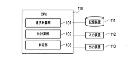
- the electric wire design apparatus includes a central processing unit (CPU) 110, a storage device 111, an input device 112, and an output device 113.
- CPU central processing unit
- the CPU 110 logically includes a resistance calculation unit 101, a ratio calculation unit 102, and a determination unit 103 as modules (logic circuits) that are hardware resources.
- the resistance calculation unit 101 reads out information on the wire type including the material, shape, wire diameter, and the like of the conductor unit 11 that is a candidate for a wire that can be produced from the storage device 111, and a specific frequency band in which the wire is used, Using the above-described equation (48), the AC resistance value due to the proximity effect of the conductor portion 11 that is a candidate for the electric wire in the specific frequency band is calculated. Furthermore, the resistance calculation unit 101 reads out information on the specific frequency band in which the electric wire is used and the reference Cu wire from the storage device 111, and uses the above-described equation (48) to determine the reference in the specific frequency band. The AC resistance value due to the proximity effect of the Cu wire to be calculated is calculated.
- the AC resistance value due to the proximity effect of the conductor part 11 and the Cu wire may be calculated at a plurality of frequencies within a specific frequency band range, and at least one frequency within the specific frequency band range (for example, a specific frequency band) The upper limit value of the frequency band may be calculated.
- the reference Cu wire may have the same wire diameter as the candidate conductor portion 11 or a different wire diameter, and can be set as appropriate.
- the ratio calculation unit 102 is a candidate conductor unit for the AC resistance value due to the proximity effect of the Cu wire at the same frequency based on the AC resistance value due to the proximity effect of the conductor portion 11 and the Cu wire calculated by the resistance calculation unit 101.
- the ratio of the AC resistance values (Rp ratio) due to the proximity effect of 11 is calculated.
- the determination unit 103 determines whether the candidate is applicable to the electric wire based on the Rp ratio calculated by the ratio calculation unit 102. For example, the determination unit 103 determines whether or not the Rp ratio is less than 1, and determines that the candidate is applicable to the electric wire when the Rp ratio is determined to be less than 1.
- the storage device 111 includes information on the equation (48) for obtaining the AC resistance due to the proximity effect, information on the plurality of candidate conductor portions 11, a specific frequency band used in each device to which the electric wire is applied, and the resistance calculation unit 101.
- the AC resistance value due to the proximity effect of the conductor part 11 and the Cu wire calculated by the above, the Rp ratio calculated by the ratio calculation part 102, the determination result by the determination part 103, and the like are stored.
- the storage device 111 for example, a semiconductor memory, a magnetic disk, an optical disk, or the like can be used.
- the storage device 111 can function as a storage device that stores a program executed by the CPU 110 (details of the program will be described later).
- the storage device 111 can temporarily store data and the like used during program execution processing in the CPU 110, and can function as a temporary data memory or the like used as a work area.
- a recognition device such as a touch panel, a keyboard, a mouse, or an OCR
- an image input device such as a scanner or a camera
- a voice input device such as a microphone
- a display device such as a liquid crystal display (LCD), an organic electroluminescence (EL) display, or a CRT display
- a printing device such as an inkjet printer or a laser printer, or the like can be used.
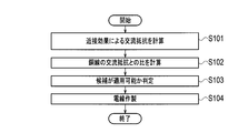
- step S101 the resistance calculation unit 101 reads out information on the conductor unit 11 that is a candidate for the electric wire and a specific frequency band in which the electric wire is used from the storage device 111, and uses the above-described formula (48). Thus, the AC resistance value due to the proximity effect of the conductor portion 11 in a specific frequency band is calculated. Furthermore, the resistance calculation unit 101 calculates the AC resistance value due to the proximity effect of the Cu wire as a reference, using the above-described equation (48). The calculated AC resistance value due to the proximity effect of the conductor part 11 and Cu is stored in the storage device 111. The AC resistance value due to the proximity effect of the conductor part 11 and Cu may be stored in advance in the storage device 111 or may be input from the input device 112. Further, the AC resistance value due to the proximity effect of the conductor part 11 and Cu may be measured instead of being calculated using a theoretical formula.
- step S102 the ratio calculation unit 102 determines the conductor part for the AC resistance value due to the proximity effect of the Cu wire based on the AC resistance value due to the proximity effect of the conductor portion 11 and the Cu wire calculated by the resistance calculation unit 101. The ratio of the AC resistance values (Rp ratio) due to the proximity effect of 11 is calculated.
- step S103 the determination unit 103 determines whether the Rp ratio calculated by the ratio calculation unit 102 is less than 1. As a result, when the Rp ratio is less than 1, it is determined that the candidate is applicable to the electric wire. The determination result is stored in the storage device 111.
- step S104 the electric wire is manufactured with the candidate material, shape, wire diameter, and the like determined to be applicable by the determination unit 103.
- a central conductor 12 made of aluminum or aluminum alloy having a diameter of about 9.5 mm to 12.0 mm is prepared.
- a coating layer 13 is formed on the surface of the central conductor 12 by performing TIG welding or plasma welding while applying a copper tape having a thickness of about 0.1 mm to 0.4 mm to the surface of the central conductor 12 by a vertical attachment method. Cover.
- the base conductor 12 made of the center conductor 12 covered with the covering layer 13 is manufactured by forming the center conductor 12 covered with the covering layer 13 into a diameter of about 9.3 mm to 12.3 mm using a skin pass.
- the base material is drawn by passing through a plurality of drawing dies of about 25 to 26 passes. By going through a plurality of wire drawing dies, the diameter of the electric wire is finally made the same as the determined wire diameter.
- the Rp ratio calculated using the equation (48) for obtaining the AC resistance due to the proximity effect is obtained. Based on this, the line type can be determined. As a result, depending on the specific frequency band in which the high-frequency wire is used, it is possible to design the wire diameter of the high-frequency wire that is less loss due to eddy currents and can reduce AC resistance compared to the reference Cu wire It becomes.
- step S102 shown in FIG. 17 the AC resistance value due to the proximity effect is calculated for each of the plurality of candidates.
- the Rp ratio is calculated for each of the plurality of candidates.
- step S103 the plurality of candidates are determined. You may determine whether each is applicable.
- step S104 if there are a plurality of applicable candidates, one of them may be selected as appropriate.
- ⁇ Wire design program> A series of procedures shown in FIG. 17, namely: (a) AC resistance due to proximity effect of conductor part 11 that is a candidate for a wire in a specific frequency band, and AC due to proximity effect of Cu wire as a reference in a specific frequency band (B) calculating the ratio of the AC resistance due to the proximity effect of the conductor part to the AC resistance due to the proximity effect of the Cu wire as a reference; (c) applying candidates to the wires based on the ratio The step of determining whether or not can be executed by controlling the electric wire design apparatus shown in FIG. 16 by an algorithm program equivalent to FIG.
- This program may be stored in the storage device 111 of the computer system constituting the electric wire designing apparatus of the present invention. Further, the program is stored in a computer-readable recording medium, and the recording medium is read into the storage device 111 or the like, whereby the series of procedures of the first embodiment of the present invention can be executed.
- “computer-readable recording medium” means a medium capable of recording a program, such as a semiconductor memory, a magnetic disk, and an optical disk.
- the main body of the electric wire design apparatus can be configured to incorporate a recording medium reader or to be externally connected. Further, it can be stored in the storage device 111 via an information processing network such as a wireless communication network.
- the electric wire according to the second embodiment of the present invention is an electric wire used in a specific frequency band, and as shown in FIG. 18, a center conductor 21 made of aluminum (Al) or an aluminum alloy, and a center conductor 2 is a CCA line provided with a coating layer 22 made of copper (Cu) that coats 21.
- the electric wire according to the second embodiment of the present invention is defined between the first frequency and the second frequency at which the AC resistance of the electric wire and the AC resistance of the Cu wire having the same wire diameter as the electric wire match.
- the specific frequency band is within a frequency band in which the AC resistance of the electric wire is larger than the AC resistance of the Cu wire.
- the diameter of the entire wire is preferably about 0.05 mm to 0.6 mm.
- the cross-sectional area of the covering layer 22 is 15% or less with respect to the cross-sectional area of the entire electric wire including the central conductor 21 and the covering layer 22, preferably about 3% to 15%, more preferably about 3% to 10%. More desirably, it is about 3% to 5%. High frequency resistance can be reduced, so that the ratio of the cross-sectional area with respect to the whole electric wire of the coating layer 22 is small.
- an aluminum alloy of electrical aluminum (EC aluminum) or an Al—Mg—Si alloy (JIS 6000 series) can be used as the central conductor 21.
- the aluminum alloy has a larger volume resistivity than EC aluminum. Therefore it is more desirable.
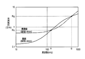
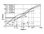
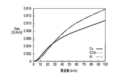
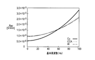
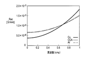
- FIG. 19 shows the relationship between frequency and AC resistance for CCA wires and Cu wires having wire diameters of 1.8 mm, 0.4 mm, and 0.2 mm.
- the AC resistance of the CCA wire is larger than the AC resistance of the Cu wire on the lower frequency side than the first frequency f11 (not shown) of about 1 kHz.
- the AC resistance of the CCA line coincides with the AC resistance of the Cu line, and eddy current loss becomes dominant on the higher frequency side than the first frequency f11.
- the magnitude of the AC resistance of the line is reversed.
- the AC resistance of the Cu line is larger than the AC resistance of the CCA line.
- the AC resistance of the CCA line again coincides with the AC resistance of the Cu line, and on the higher frequency side than the second frequency f12, the influence of the proximity effect of the CCA line becomes larger than that of the Cu line.
- the magnitudes of the AC resistance of the wire and the AC resistance of the Cu wire are reversed.
- the AC resistance of the CCA wire and the AC resistance of the Cu wire coincide with each other at the first frequency f21 and the second frequency f22.
- the AC resistance of the Cu line is larger than the AC resistance of the CCA line.
- the AC resistance of the CCA wire and the AC resistance of the Cu wire coincide with each other at the first frequency f31 and the second frequency f32.
- the AC resistance of the Cu line is larger than the AC resistance of the CCA line.
- the first frequency f11 and the second frequency f12 shift to the high frequency side as the diameters of the CCA line and the Cu line are reduced to 1.8 mm, 0.4 mm, and 0.2 mm.
- the frequency bands B1, B2, and B3 defined between the first frequencies f11, f21, and f31 and the second frequencies f12, f22, and f32 were found to shift to the high frequency side. Even if the strength of the magnetic field increases, the second frequencies f12, f22, and f32 hardly change, but the first frequencies f11, f21, and f31 move to the low frequency side.
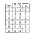
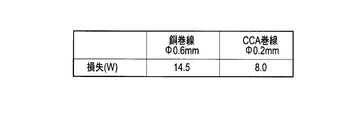
- the loss (copper loss) generated in the high-frequency transformer is the sum of the DC component, the reference frequency, and the higher-order harmonic component.
- the loss of the 0.2 mm diameter CCA winding according to the second embodiment of the present invention is 8.0 W
- the loss of the 0.6 mm diameter copper winding according to the comparative example. Is 14.5W.
- the frequency band of the alternating current used for the CCA line is defined by the first frequency f11, f21, f31 and the second frequency f12, f22, f32 from the reference frequency to the higher order harmonic components. It is preferable that the diameter, material, cross-sectional area ratio, and the like of the CCA line are designed so as to be within the frequency bands B1, B2, and B3. To what extent higher-order harmonic components are taken into consideration may be determined as appropriate according to the use of the CCA line. For example, from the reference frequency to the 10th harmonic component may be considered, or from the reference frequency to the 20th harmonic component may be considered.
- the loss due to eddy current when used in a specific frequency band, is equal to or smaller than that of a Cu wire having the same wire diameter. AC resistance can be reduced.
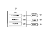
- the electric wire design apparatus includes a central processing unit (CPU) 210, a storage device 211, an input device 212, and an output device 213.
- CPU central processing unit
- the CPU 210 logically includes an AC resistance calculation unit 201, a frequency extraction unit 202, and a wire diameter extraction unit 203 as modules (logic circuits) that are hardware resources.
- the AC resistance calculation unit 201 reads information necessary for calculating the AC resistance of the target CCA line and Cu line from the storage device 211, and, as shown in FIG. 19, according to a plurality of frequencies, the CCA line And AC resistance of Cu wire having the same wire diameter as CCA wire are calculated for each of a plurality of wire diameters.
- the frequency extraction unit 202 Based on the AC resistance of the CCA line calculated by the AC resistance calculation unit 201 and the AC resistance of the Cu wire having the same wire diameter as the CCA line, the frequency extraction unit 202, for each of a plurality of wire diameters, as shown in FIG.
- f12, f22, and f32 are extracted (f11 is not shown).
- the frequency extracted as the first frequencies f11, f21, and f31 and the second frequencies f12, f22, and f32 may not be a point where the AC resistance of the CCA line and the AC resistance of the Cu line exactly match.
- the frequency immediately before (low frequency side) or just after (high frequency side) switching between the AC resistance of the CCA line and the AC resistance of the Cu line may be extracted, or the AC resistance of the CCA line and the AC resistance of the Cu line. It is also possible to obtain respective approximate curves from the calculation results and extract the frequencies at which these approximate curves intersect.
- the wire diameter extraction unit 203 reads the specific frequency band in which the CCA line is used from the storage device 211, and extracts the first frequencies f11, f21, f31 and the second frequencies f12, f22, f31 extracted by the frequency extraction unit 202. Based on f32, among the plurality of wire diameters, the frequency bands B1, B2, and B3 defined between the extracted first frequencies f11, f21, and f31 and the second frequencies f12, f22, and f32 are CCA.
- the diameter of the CCA line corresponding to the first frequency and the second frequency such that the line falls within the specific frequency band used (for example, the diameter 0 corresponding to the first frequency f21 and the second frequency f22). .4 mm).
- the specific frequency band in which the CCA line is used may include, for example, the reference frequency and the 10th and lower harmonic frequencies shown in FIG. 21, and include the reference frequency and the 20th and lower harmonic frequencies. May be.
- the storage device 211 shown in FIG. 23 includes information necessary for calculating the AC resistance of CCA wires and Cu wires having various wire diameters, a specific frequency band in which each CCA line is used, and an AC resistance calculation unit 201.
- the first resistances f11, f21, f31 and the second frequencies f12, f22, f32 extracted by the frequency extraction unit 202 and the wire diameter of the CCA line extracted by the wire diameter extraction unit 203 are stored.
- a semiconductor memory, a magnetic disk, an optical disk, or the like can be employed.
- the storage device 211 can function as a program storage device or the like that stores a program executed by the CPU 210 (details of the program will be described later).
- the storage device 211 can temporarily store data and the like used during the program execution process in the CPU 210, or can function as a temporary data memory or the like used as a work area.
- a recognition device such as a touch panel, a keyboard, a mouse, or an OCR
- an image input device such as a scanner or a camera
- a voice input device such as a microphone
- the output device 213 a display device such as a liquid crystal display (LCD), an organic electroluminescence (EL) display, or a CRT display, or a printing device such as an ink jet printer or a laser printer can be used.
- LCD liquid crystal display
- EL organic electroluminescence
- CRT display or a printing device such as an ink jet printer or a laser printer
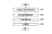
- step S201 the AC resistance calculation unit 201 calculates the AC resistance of the CCA line and the AC resistance of the Cu line having the same wire diameter as the CCA line for each of the plurality of wire diameters. This calculation result is stored in the storage device 211.
- the material and cross-sectional area ratio of the CCA line to be calculated can be set as appropriate.
- the AC resistance of the CCA line and the AC resistance of the Cu line may be actually measured instead of being calculated.
- step S202 the frequency extraction unit 202 matches the AC resistance of the CCA line and the AC resistance of the Cu line for each of the plurality of wire diameters, and the CCA line
- the range of the wire diameter and the frequency range to be calculated can be appropriately set within the range that can be used as the CCA line.
- the extracted first frequencies f11, f21, and f31 and second frequencies f12, f22, and f32 are stored in the storage device 211.
- the wire diameter extraction unit 203 defines a frequency defined between the extracted first frequencies f11, f21, and f31 and the second frequencies f12, f22, and f32 among the plurality of wire diameters.
- the diameters of the CCA lines corresponding to the first frequency and the second frequency (for example, the first frequency f11 and the second frequency) such that the bands B1, B2, and B3 are within a specific frequency band using the CCA line.
- a wire diameter of 1.8 mm corresponding to the frequency f12 is extracted.
- the extracted wire diameter is stored in the storage device 211.
- a CCA strand having a wire diameter stored in the storage device 211 is manufactured. That is, a central conductor 21 made of aluminum or aluminum alloy having a diameter of about 9.5 mm to 12.0 mm is prepared. A coating layer 22 is formed on the surface of the central conductor 21 by performing TIG welding or plasma welding or the like while applying a copper tape having a thickness of about 0.1 mm to 0.4 mm to the surface of the central conductor 21 by a vertical attachment method. Cover. Next, the base conductor 21 made of the center conductor 21 covered with the covering layer 22 is manufactured by forming the center conductor 21 covered with the covering layer 22 into a diameter of about 9.3 mm to 12.3 mm using a skin pass. Next, the base material is drawn by passing through a plurality of drawing dies of about 25 to 26 passes. By going through a plurality of wire drawing dies, the diameter of the electric wire is finally made the same as the wire diameter stored in the storage device 211.
- the same wire diameter is used according to the specific frequency band in which the CCA wire is used.
- the loss due to eddy current can be made equal to or smaller than that of the Cu wire, and the diameter of the CCA wire that can reduce the AC resistance can be designed.
- the first frequencies f11, f21, f31 and the second frequencies f12, f22, f2 and f22 such that the frequency bands B1, B2, B3 defined between f22 and f32 fall within a specific frequency band using the CCA line.
- f32 Step extracting a wire diameter of, or the like, by 24 equivalent algorithm program, wire design device control to be executed as shown in FIG. 23.
- This program may be stored in the storage device 211 of the computer system constituting the electric wire designing apparatus of the present invention.
- the program is stored in a computer-readable recording medium, and the recording medium is read into the storage device 211 or the like, whereby the series of procedures according to the second embodiment of the present invention can be executed.
- “computer-readable recording medium” means a medium capable of recording a program, such as a semiconductor memory, a magnetic disk, and an optical disk.
- the main body of the electric wire design apparatus can be configured to incorporate a recording medium reader or to be externally connected. Further, it can be stored in the storage device 211 via an information processing network such as a wireless communication network.
- An electric motor that adjusts rotational speed and torque using an inverter device or the like is highly efficient, and is used in a wide range of fields such as inverter air conditioners in the drive of railway vehicles and electric vehicles, and home appliances.
- the coil of the electric motor is constructed by winding a conducting wire multiple times.
- Cu copper
- Al aluminum
- Cu wires are generally used for conventional coils.
- this type of electric motor has a variable rotation speed and is often used at a high rotation speed.
- the drive current of the electric motor has a higher frequency according to the rotation speed.
- the inverter device creates a high frequency by appropriately turning on and off the DC voltage. For this reason, the drive current has a higher frequency component than the fundamental frequency component.
- the resistance of the coil increases due to the skin effect and proximity effect.
- the resistance due to the skin effect is always greater for the Al line than for the Cu line, but the resistance due to the proximity effect may be greater for the Cu line.
- the high frequency resistance may increase due to the proximity effect, and the loss due to this may increase. In particular, the loss becomes significant when the operating frequency becomes high or when the inverter device is used for driving.
- the coil has various shapes, and if the shape is different, the ratio of the skin effect and the proximity effect in the high-frequency resistance of the conductive wire is different.
- the skin effect is determined by the cross-sectional shape of the conducting wire constituting the coil, the number of conducting wires, and the length of the conducting wire, but the proximity effect also depends on how the coil is wound. When a conducting wire is wound in the vicinity or the number of turns is large, the proximity effect becomes strong.
- the high frequency resistance per unit length of the conducting wire constituting the coil can be expressed as the following equation (49).
- R ac R s + ⁇ 2 P p (49)
- R s unit: ⁇ / m
- P p unit: ⁇ ⁇ m
- ⁇ The unit is 1 / m
- ⁇ is a shape factor (structure factor) depending on the shape of the coil.
- ⁇ is a constant substantially independent of frequency, and becomes larger when the coil winding is densely wound, and becomes larger as the winding wire is longer.
- ⁇ varies depending on the required output of the electric motor and the like.
- R s and P p are given by the following equations (50) and (51), respectively.
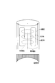
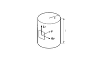
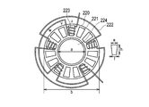
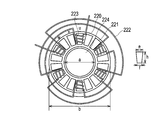
- the electric motor (three-phase AC synchronous motor) according to the first example of the second embodiment of the present invention includes a plurality of iron cores 221 arranged in a circular shape, and an Al wire.
- the electric wire 222 which consists of a CCA wire is provided with the some coil 223 wound around the some iron core 221, and the rotor 224 rotated by applying an electric current to the some coil 223.
- a plurality of iron cores 221, a plurality of coils 223, a coil holding part 20, and the like constitute a stator.
- the electric motor according to the first example of the second embodiment of the present invention is 12 coils, the inner diameter a of the coil holding part 20 is 150 mm, the outer diameter b of the coil holding part 20 is 200 mm, and the length of the iron core 221 is long.
- the length h is 40 mm, the diameter e of one end on the outer peripheral side of the iron core 221 is 30 mm, and the diameter f of the other end of the iron core 221 is 20 mm.
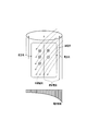
- Each pole is wound around the iron core 21 in a cylindrical shape by an electric wire 222 having a radius r of 0.8 mm, and the total length l is about 3.1 m.
- the u-phase coil 223 is shown in FIG. 25, the v-phase and w-phase coils that are not shown also have the same structure as the coil 223.
- the rotor 224 is made of a permanent magnet.
- the rotor 224 is attracted and rotated by the surrounding rotating magnetic field generated by the alternating current applied to the coil 223.
- the electric motor according to the first example of the second embodiment of the present invention uses a variable voltage variable frequency (VVVF) type inverter device, and adjusts the frequency of the drive current in an inverter manner, thereby providing an electric motor.
- VVVF variable voltage variable frequency
- the inverter device is, for example, a three-phase output inverter using six switching elements, and artificially creates a three-phase alternating current using the switching elements.
- the AC resistance of the coil 223 falls between the first frequency that is smaller than the AC resistance of the coil wound with the Cu wire having the same shape as the coil 223 and the second frequency that is higher than the first frequency.
- the frequency of the alternating current applied to the coil 223 is controlled by the inverter method.
- the drive current has, for example, a high frequency component having an amplitude of 1/3 or more of the fundamental frequency component, and a power having a high frequency component having 1/9 or more of the fundamental frequency component.
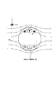
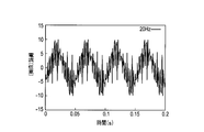
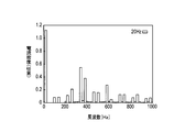
- 26 and 27 show current waveforms when the operating frequency is 20 Hz and 50 Hz, respectively, in the electric motor shown in FIG. FIG. 28 is obtained by extending the time axis of FIG. 27 by 2.5 times and superimposing it on FIG. According to FIG. 26, the current has a basic period of 0.05, but since there is an inverter system that cuts out a variable voltage and generates a high frequency, there are many places where the sinusoidal waveform changes rapidly. In FIG. 27, the fundamental period is 0.02 s. From FIG. 28, it can be seen that the configuration of the sine wave waveform is almost constant without depending on the frequency.
- FIG. 29 represents the frequency spectrum of FIG. As shown in FIG. 29, it can be seen that in addition to the fundamental frequency of 20 Hz, there are many high-frequency components. The high-frequency resistance becomes higher than the presence of these high-frequency components, and the loss due to the proximity effect becomes more remarkable.
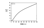
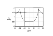
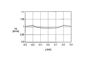
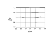
- FIG. 30 shows a high-frequency resistance R s per unit length due to the skin effect when a coil is wound with Cu wire having a radius r of 0.8 mm and a length l of 3.1 m, and an external magnetic field H 0.
- H 0 1A / mm
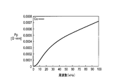
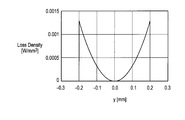
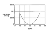
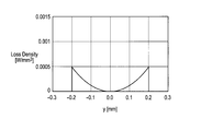
- the loss P P per unit length due to the proximity effect in Figure 31.
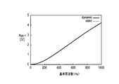
- the coil wound with the same Cu wire shows the static characteristic of the high frequency resistance as shown in FIG.
- the static characteristics refer to characteristics when a sinusoidal current is passed through the electric motor.
- f n is the frequency of the n-th order frequency components.
- the drive current in FIG. 26 is created by the inverter device, and assuming that the waveform constituting the sine wave does not change relatively even if the frequency changes, and calculating the dynamic characteristics of the high frequency resistance of the coil by the equation (52), The calculation result shown in FIG. 33 is obtained.
- the dynamic characteristics refer to characteristics when a periodic drive current as shown in FIG. 26 is passed through the electric motor.
- the fundamental frequency is the reciprocal of the driving current cycle. It can be seen from FIG. 33 that the dynamic characteristic (dynamic) is much larger than the static characteristic (static).
- the electric wire 222 around which the coil 223 is wound has the same diameter, and aluminum (Al) or aluminum as shown in FIG.
- a CCA line (hereinafter referred to as “CCA line”) comprising a central conductor 21 made of an alloy and a covering layer 22 made of copper (Cu) covering the central conductor 21, wherein the cross-sectional area of the covering layer 22 is 5% of the cross-sectional area of the entire high-frequency electric wire.
- CCA line a CCA line
- Cu copper
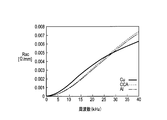
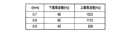
- the dynamic characteristics of the high frequency resistance of the coil wound with the same CCA wire and Al wire are shown in FIG. 36 and FIG. 36 and 37 that the resistance of the CCA line and the Al line is smaller than that of the Cu line when the frequency f is in the range of 65 Hz ⁇ f ⁇ 1173 Hz.
- the first frequency is set to 65 Hz
- the second frequency is set to 1173 Hz
- the frequency of the drive current is controlled in the range of 65 Hz ⁇ f ⁇ 1173 Hz, thereby obtaining a high-frequency resistance equivalent to or smaller than the Cu wire. be able to.
- the first frequency and the second frequency at which each of the CCA line and the Al line has a high frequency resistance equivalent to or lower than that of the Cu line can be expressed by the following equations (49) to (52). It may be obtained by calculation using it, or may be obtained by actual measurement.
- the electric wire 222 having a circular cross section has been described.
- the cross sectional shape of the electric wire 222 may be flat or rectangular, and the cross sectional area is 2.0 mm 2. If so, the same effect is obtained in the case of the CCA line.
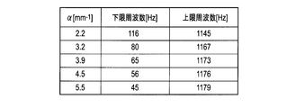
- the density of the winding of the electric motor used and the length of the conducting wire are changed, the same effect can be obtained even when ⁇ is changed to 2.2 mm ⁇ 1 ⁇ ⁇ ⁇ 5.5 mm ⁇ 1 .
- FIG. 38 shows a frequency band in which the dynamic characteristic high-frequency resistance of the CCA wire for different ⁇ values is smaller than that of the Cu wire in a coil wound with the same shape of conducting wire. It can be seen that the frequency band in which the CCA line is advantageous increases as ⁇ increases (for example, as the conducting wire is tightly wound or wound many times).
- the Al wire or the CCA wire having lower conductivity than the Cu wire is used, and the first inverter is used.
- the frequency of the drive current between the frequency and the second frequency it is possible to reduce the high-frequency resistance equivalent to or lower than that of the Cu wire and the loss of the electric motor.
- Al is lighter than copper (Cu)
- Cu copper
- the CCA wire when used, since it can be soldered as in the past, the high frequency resistance can be reduced and the weight can be reduced without impairing the workability. Further, when the skin depth of the CCA wire is about the thickness of the copper layer, the loss due to the skin effect is about the same as that of the conventional conductor.
- an electric motor (three-phase AC synchronous motor) according to a second example of the second embodiment of the present invention includes a plurality of iron cores 221 arranged in a circle and an Al wire.
- the electric wire 222 which consists of a CCA wire is provided with the some coil 223 wound around the some iron core 221, and the rotor 224 rotated by applying an electric current to the some coil 223.
- the electric motor according to the second example of the second embodiment of the present invention has 15 coils, the inner diameter a of the coil holding part 20 is 170 mm, the outer diameter b of the coil holding part 20 is 220 mm, and the length of the iron core 221.
- the length h is 45 mm
- the diameter e of one end on the outer peripheral side of the iron core 221 is 33 mm
- the diameter f of the other end of the iron core 221 is 25 mm.
- Each pole is wound around the iron core 21 in a cylindrical shape by an electric wire 222 having a radius r of 1.0 mm, and the total length l is about 4.8 m.
- the u-phase coil 223 is shown in FIG. 40, the v-phase and the w-phase also have the same coil structure as the coil 223.
- a 5% CCA line and an Al line having a radius r of 1.0 mm and a length of 4.8 m are used, and Cu is used as a comparative example.
- a line was used.
- the coil wound with these conducting wires exhibits high-frequency resistance static characteristics as shown in FIGS.
- FIG. 45 and FIG. 46 show the high-frequency resistance dynamic characteristics when it is assumed that the drive current of FIG. 26 is generated by an inverter and the waveform constituting the sine wave does not change relatively even if the frequency changes.
- the frequency f is 59 Hz ⁇ f ⁇ 742 Hz and the resistance of the CCA line and the Al line is smaller than that of the Cu line.
- the first frequency is set to 59 Hz
- the second frequency is set to 742 Hz
- the frequency of the drive current is controlled in a range of 59 Hz ⁇ f ⁇ 742 Hz, thereby obtaining a high-frequency resistance equivalent to or smaller than the Cu line. be able to.
- the electric wire 222 having a circular cross section has been described.
- the cross section of the electric wire 222 may be flat or rectangular, and the cross sectional area is 3.1 mm 2. If so, the same effect is obtained in the case of the CCA line.
- the value of ⁇ is 1. The same effect can be obtained even when .0 mm ⁇ 1 ⁇ ⁇ ⁇ 4.5 mm ⁇ 1 is changed.
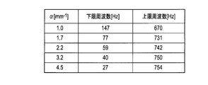
- FIG. 47 shows a frequency band in which the dynamic characteristic high-frequency resistance of the CCA wire for different ⁇ values is smaller than that of the Cu wire in a coil wound with the same shape of conducting wire. It can be seen that the frequency band in which the CCA line is more advantageous than the Cu line is widened as the value of ⁇ increases (as it is tightly wound or wound more).
- an electric motor (three-phase AC synchronous motor) according to a third example of the second embodiment of the present invention has a plurality of iron cores 221 and an electric wire 222 made of Al wires or CCA wires. Includes a plurality of coils 223 wound around a plurality of iron cores 221 and a rotor 224 that rotates by applying a current to the plurality of coils 223.
- the electric motor according to the third example of the second embodiment of the present invention has 18 coils, the inner diameter a of the coil holding part 20 is 180 mm, the outer diameter b of the coil holding part 20 is 230 mm, and the length of the iron core 221 is long.
- the length h is 50 mm
- the diameter e of one end on the outer peripheral side of the iron core 221 is 36
- the diameter f of the other end of the iron core 221 is 27 mm
- each pole has a cylindrical shape with an electric wire 222 having a radius r of 1.2 mm.
- the total length l was about 7.0 m.
- FIG. 49 only the u-phase coil is shown, but the v-phase and w-phase coils, which are not shown, also have the same structure as the coil 223.
- a 5% CCA wire and an Al wire having a radius r of 1.2 mm and a length of 7.0 m are used, and a Cu wire is used as a comparative example. It was used.
- the outer diameter b of the coil holding part 20 was 1.17 mm, and the inner diameter a of the coil holding part 20 was 1.2 mm.
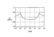
- the frequency resistance R s per unit length due to the skin effect of the case shown in FIG. 50, when the external magnetic field H 0 and H 0 1A / mm, Figure loss P P per unit length due to the proximity effect 51 Shown in
- the coil wound by these conducting wires shows the static characteristic of a high frequency resistance as shown in FIG.52 and FIG.53.
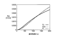
- FIG. 54 and FIG. 55 show the high-frequency resistance dynamic characteristics when it is assumed that the drive current of FIG. 26 is generated by an inverter device and the waveform constituting the sine wave does not change relatively even if the frequency changes.
- the frequency f is 48 Hz ⁇ f ⁇ 511 Hz and the resistance of the CCA line and the Al line is smaller than that of the Cu line.
- the first frequency to 48 Hz and the second frequency to 511 Hz and controlling the frequency of the drive current at 48 Hz ⁇ f ⁇ 511 Hz
- a high frequency resistance equivalent to or smaller than the Cu wire can be obtained. .
- the electric wire 222 having a circular cross section has been described.
- the cross sectional shape of the electric wire 222 may be flat or rectangular, and the cross sectional area is 4.5 mm 2. If so, the same effect is obtained in the case of the CCA line.
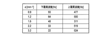
- alpha is 0.9mm -1 ⁇ ⁇ ⁇ 3. The same effect is obtained even when the value is changed to 2 mm ⁇ 1 .
- FIG. 56 shows a frequency band in which the dynamic high frequency resistance of the CCA line for different ⁇ values is smaller than that of the Cu line in a coil wound with the same shape of conducting wire. From FIG. 56, it can be seen that the frequency band in which the CCA line is advantageous increases as ⁇ becomes larger (closer or more wound).
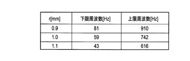
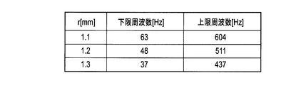
- FIG. 57 shows a frequency band where the CCA line has a lower dynamic characteristic high frequency resistance than the Cu line when the value of ⁇ is 1.6 mm ⁇ 1 and the radius r is different. From FIG. 57, it can be seen that the thicker the wire diameter, the more advantageous the CCA line on the low frequency side.
- CCA wires and Cu wires having wire diameters of 1.8 mm, 0.4 mm, and 0.2 mm have been described.
- the present invention is not particularly limited to these three wire diameters.
- the present invention may be applied to CCA wires and Cu wires having various wire diameters.
- the electric wire according to the present invention is an electric motor using various coils.
- the present invention can be applied to a motor, and the electric motor according to the present invention can be applied to various types of electric motors having a coil wound with a CCA wire or an Al wire.
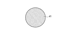
- the electric wire according to the third embodiment of the present invention includes a conductor portion 31 made of a material having a higher volume resistivity than copper.
- the AC resistance of the electric wire and the AC resistance of the Cu wire having the same wire diameter as the electric wire match each other, and the AC resistance of the electric wire is Cu wire between each other.
- the volume resistivity of the conductor portion 31 is set so that the second frequency is equal to or higher than the upper limit value of the specific frequency band among the first frequency smaller than the AC resistance and the second frequency larger than the first frequency.
- the DC resistance value per unit length divided by the cross-sectional area is specified.
- the diameter of the conductor portion 31 is preferably about 0.05 mm to 0.6 mm, but is not particularly limited.
- copper alloys such as brass, phosphor bronze, quartz bronze, copper-beryllium alloy, and copper-nickel-silicon alloy, can be used.
- Brass is an alloy (Cu—Zn) containing copper (Cu) and zinc (Zn), and may contain a small amount of elements other than copper and zinc.
- Silica bronze is an alloy (Cu—Sn—Si) containing copper, tin (Sn) and silicon (Si), and may contain a small amount of elements other than copper, tin and silicon.
- Phosphor bronze is an alloy (Cu—Sn—P) containing copper, tin and phosphorus (P), and may contain a small amount of elements other than copper, tin and phosphorus.
- These copper alloy wires are, for example, one-principle annealed and may be plated with tin, copper, chromium (Cr), or the like. Further, the conductor portion 31 may have a flat shape or the like in addition to the cylindrical shape.
- the electric wire according to the third embodiment of the present invention includes a central conductor 32 made of aluminum (Al) or an aluminum alloy, and copper (Cu) covering the central conductor 32.
- the CCA line provided with the covering layer 33 made of may be used as the conductor portion 31.
- the diameter of the entire CCA line is preferably about 0.05 mm to 0.6 mm.
- the cross-sectional area of the covering layer 33 is 15% or less with respect to the cross-sectional area of the entire electric wire including the central conductor 32 and the covering layer 33, preferably about 3% to 15%, more preferably about 3% to 10%. More desirably, it is about 3% to 5%. High frequency resistance can be reduced, so that the ratio of the cross-sectional area with respect to the whole electric wire of the coating layer 33 is small.
- the center conductor 32 for example, an aluminum alloy of electrical aluminum (EC aluminum) or an Al—Mg—Si based alloy (JIS6000 series) can be used, but the aluminum alloy has a larger volume resistivity than EC aluminum. Therefore it is more desirable.
- the electric wire according to the third embodiment of the present invention has a smaller eddy current loss than a Cu wire having the same wire diameter due to the proximity effect in a specific frequency band, resulting in a smaller AC resistance. I found the characteristics.
- FIG. 13 shows the relationship between the frequency and the AC resistance when the external magnetic field strength H is 1 A / mm for the brass wire having a wire diameter of 0.4 mm and the Cu wire as a comparative example.
- the AC resistance of the brass wire is larger than the AC resistance of the Cu wire.
- the AC resistance of the brass wire matches the AC resistance of the Cu wire, and eddy current loss becomes dominant on the higher frequency side than the first frequency f1, so the AC resistance of the brass wire and Cu
- the magnitude of the AC resistance of the line is reversed.
- the AC resistance of the Cu wire is larger than the AC resistance of the brass wire.
- the AC resistance of the brass wire again coincides with the AC resistance of the Cu wire, and on the higher frequency side than the second frequency f2, the influence of the proximity effect of the brass wire becomes larger than that of the Cu wire, and brass.
- the magnitudes of the AC resistance of the wire and the AC resistance of the Cu wire are reversed.
- FIG. 14 shows the relationship between the frequency when the external magnetic field strength H for a brass wire having a diameter of 0.4 mm is 1 A / mm, the sum of the skin effect component R s and the DC resistance component R dc , and the proximity effect component R p. .
- DC resistance R dc the frequency is a value of the AC resistance at 0.
- the skin effect component R s and the proximity effect component R p have frequency dependence, but as shown in FIG. 14, if the frequency is less than 1 MHz, the proximity effect component R p is more than the skin effect component R s. The dependence is remarkable, and the skin effect component R s is a negligible level.
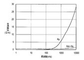
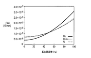
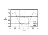
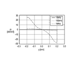
- FIG. 59 shows the relationship between the frequency and the AC resistance when the external magnetic field strength H of the brass wire and the Cu wire having a diameter of 0.4 mm is 1 A / mm and 5 A / mm, respectively.
- the proximity effect component R p is a significant field strength-dependent than the skin effect component R s.
- AC resistance R ac of the second frequency f12, f22 proximity effect component R p accounts for most of the second to the magnetic field strength is proportional to uniformly increase the Cu lines and brass wire both be increased The frequencies f12 and f22 hardly change.
- the first frequency f11, f21 is large influence of the DC resistance component R dc is the proximity effect component R p between the external magnetic field strength increases is shifted to the low frequency side increases.
- the direct current resistance per unit length obtained by dividing the volume resistivity of the metal applied to the conductor by the cross-sectional area is defined as “reference direct current resistance”.
- the reference DC resistance and the second frequency were obtained by calculation using the conductor material and wire diameter.
- the conductor portion 31 shown in FIG. 58 (a) is made of pure aluminum
- the central conductor 32 shown in FIG. 58 (b) is made of aluminum
- the cross-sectional area of the covering layer 33 is an electric wire.
- 5% CCA 5% of the entire cross-sectional area
- the cross-sectional area of the covering layer 33 is 10% of the cross-sectional area of the entire electric wire (10 % CCA)
- the central conductor 32 shown in FIG. 58 (b) is made of aluminum
- the cross-sectional area of the covering layer 33 is 15% of the cross-sectional area of the entire wire (15% CCA), shown in FIG. 58 (b).
- the central conductor 32 is made of alloy aluminum
- the cross-sectional area of the covering layer 33 is 5% of the cross-sectional area of the entire electric wire (5% CCA (alloy Al))
- Each made of brass, quartz bronze and phosphor bronze It shows the calculated results for things.
- the volume resistivity of the CCA line was an equivalent volume resistivity obtained by conversion with the cross-sectional area ratio of the two layers.
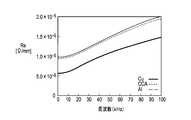
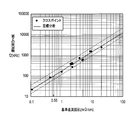
- a regression line as shown by a solid line in FIG. 61 was obtained. That is, the reference DC resistance Rdc, the second frequency as f 2, has been found to be the following relationship (49).
- the electric wire according to the third embodiment of the present invention uses the formula (53), and the reference of the conductor portion 31 so as to have the second frequency equal to or higher than the upper limit value of the specific frequency band in which the electric wire is used.
- DC resistance value is specified. That is, the volume resistivity, the cross-sectional area, the material, the shape, the wire diameter, and the like of the conductor portion 31 are defined so that the reference DC resistance value is obtained.
- the second frequency is set to, for example, about 100 kHz or more, and thus the reference DC resistance is set to about 0.55 m ⁇ / cm or more. It is desirable to set to.
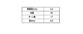
- the brass wire which concerns on the 3rd Embodiment of this invention uses 17 strands of diameter 0.4mm, length 6.6m, and 17 turns.
- a magnetic field generating coil for an IH cooker was produced with a litz wire structure, and a characteristic confirmation test was performed on them.
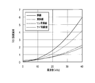
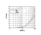
- the test results are shown in FIGS.
- a high frequency current of about 20 kHz to 60 kHz is generally used for an IH cooker, but it can be seen that the AC resistance of the brass wire is smaller than the AC resistance of the Cu wire in a frequency band including about 20 kHz to 60 kHz. .
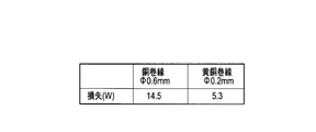
- the loss (copper loss) generated in the high-frequency transformer is the sum of the DC component, the reference frequency, and the higher-order harmonic component.
- the loss of the 0.2 mm diameter brass winding according to the third embodiment of the present invention is 5.3 W
- the loss of the 0.6 mm diameter copper winding according to the comparative example. Is 14.5W.
- the second frequency is set to be higher than the higher harmonic component of the alternating current used.
- higher-order harmonic components may be appropriately determined according to the use of the electric wire. For example, from the reference frequency to the 10th harmonic component may be considered, or from the reference frequency to the 20th harmonic component may be considered.
- the reference direct current of the conductor portion 31 of the electric wire is used so that the second frequency becomes equal to or higher than the upper limit value of the specific frequency band using the equation (53). Resistance value is specified.
- FIG. 61 shows two broken lines of 0.7 times and 1.3 times of the regression line shown by the solid line.
- the reference DC resistance value is defined within the bandwidth range between the two broken lines shown in FIG. May be. That is, the reference DC resistance value R dc of the high-frequency electric wire according to the third embodiment of the present invention is set to a second frequency f 2 , 0.7 ⁇ 10 (0.925 ⁇ log Rdc + 2.24) ⁇ f 2 ⁇ 1.3 ⁇ 10 (0.925 ⁇ log Rdc + 2.24) (54) You may prescribe in relation to.
- the reference DC resistance value can be widened in an effective range, and the degree of freedom in designing the volume resistivity, cross-sectional area, material, shape, wire diameter, etc. of the conductor portion 31 that defines the reference DC resistance value. Can be improved.
- the reference DC resistance value R dc is set to an upper limit value f 0 of a specific frequency band, f 0 ⁇ 10 (0.925 ⁇ log Rdc + 2.24) (55) You may prescribe
- the second frequency can be set to be equal to or higher than the upper limit value of the specific frequency band, and the reference DC resistance value can be specified in a range satisfying the relationship of Expression (55), so that the reference DC resistance value is specified.
- the degree of freedom in design such as volume resistivity, cross-sectional area, material, shape, and wire diameter of the conductor portion 31 can be improved.
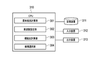
- the electric wire design apparatus includes a central processing unit (CPU) 310, a storage device 311, an input device 312, and an output device 313.
- CPU central processing unit
- the CPU 310 logically includes a specific resistance calculation unit 301, a frequency setting unit 302, a target resistance calculation unit 303, and a line type selection unit 304 as modules (logic circuits) that are hardware resources.
- the specific resistance calculation unit 301 reads necessary information from the storage device 311 and calculates a specific reference DC resistance value for each line type including a combination of a material, a shape, a wire diameter, and the like that can be produced.
- the reference DC resistance value for each line type may be stored in advance in the storage device 311 or may be input from the input device 312.
- the frequency setting unit 302 reads a specific frequency band in which the designed electric wire is used from the storage device 311, and the AC resistance of the electric wire and the AC resistance of the Cu wire having the same wire diameter as the electric wire match each other.
- the second frequency is a value equal to or higher than the upper limit value of the specific frequency band.
- the second frequency is set so that the second frequency matches the upper limit value of a specific frequency band.
- the upper limit value of the specific frequency band for example, the second frequency may be set higher than the 10th harmonic frequency, or the second frequency may be set higher than the 20th harmonic frequency. good.
- the target resistance calculation unit 303 calculates a target reference DC resistance value from the second frequency set by the frequency setting unit 302 using the equation (53) or the equation (54). Further, the target resistance calculation unit 303 reads a specific frequency band in which the electric wire designed by the storage device 311 is used, and calculates a target reference DC resistance value so as to satisfy the relationship of Expression (55). good.
- the line type selection unit 304 selects the type of electric wire according to the reference DC resistance value calculated by the specific resistance calculation unit 301 and the target resistance calculation unit 303, respectively. That is, the line type selection unit 304 has the reference DC resistance value specific to the plurality of line types calculated by the specific resistance calculation unit 301 among the plurality of line types as the target calculated by the target resistance calculation unit 303. Select a line type that is greater than or equal to the reference DC resistance value.
- the storage device 311 is information necessary to calculate the reference DC resistance values of a plurality of line types, a specific frequency band used in each device to which the electric wire is applied, and information related to Expression (53) or Expression (54). , The reference DC resistance value calculated by the specific resistance calculation unit 301, the second frequency set by the frequency setting unit 302, the reference DC resistance value calculated by the target resistance calculation unit 303, and the line type determined by the line type selection unit 304 Save etc.
- the storage device 311 for example, a semiconductor memory, a magnetic disk, an optical disk, or the like can be employed.
- the storage device 311 can function as a storage device that stores a program executed by the CPU 310 (details of the program will be described later).
- the storage device 311 can temporarily store data used during the program execution processing in the CPU 310, or can function as a temporary data memory used as a work area.
- a recognition device such as a touch panel, a keyboard, a mouse, or an OCR
- an image input device such as a scanner or a camera
- a voice input device such as a microphone
- a display device such as a liquid crystal display (LCD), an organic electroluminescence (EL) display, or a CRT display, or a printing device such as an ink jet printer or a laser printer can be used.
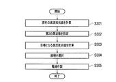
- step S301 the specific resistance calculation unit 301 reads necessary information from the storage device 311 and calculates a reference DC resistance value for each line type including a combination of the material, shape, wire diameter, and the like of the high-frequency electric wire. .
- the calculated reference DC resistance value is stored in the storage device 311.
- the reference DC resistance value for each line type may be stored in advance in the storage device 311 or may be input from the input device 312. Further, the reference DC resistance value for each line type may be actually measured instead of being calculated using a theoretical formula.
- step S302 the frequency setting unit 302 reads out a specific frequency band in which the electric wire designed from the storage device 311 is used, and the AC resistance of the electric wire and the AC resistance of the Cu wire having the same wire diameter as the electric wire.
- the set second frequency is stored in the storage device 311.
- step S3 the target resistance calculation unit 303 calculates the reference DC resistance value from the second frequency set by the frequency setting unit 302 using the formula (53) or the formula (54).
- the calculated reference DC resistance value is stored in the storage device 311. Further, the target resistance calculation unit 303 reads a specific frequency band in which the electric wire designed by the storage device 311 is used, and calculates a target reference DC resistance value so as to satisfy the relationship of Expression (55). good.
- step S304 the line type selection unit 304 determines that the reference DC resistance value calculated by the specific resistance calculation unit 301 among the plurality of line types is calculated by the target resistance calculation unit 303. Determine the line type that is greater than or equal to the value. The determined line type is stored in the storage device 311.
- step S305 an electric wire having a wire type composed of a combination of the material, shape, wire diameter, and the like determined by the wire type selecting unit 304 is manufactured.
- a central conductor 32 made of aluminum or aluminum alloy having a diameter of about 9.5 mm to 12.0 mm is prepared.
- a coating layer 33 is formed on the surface of the central conductor 32 by performing TIG welding or plasma welding or the like while applying a copper tape having a thickness of about 0.1 mm to 0.4 mm to the surface of the central conductor 32 by a vertical attachment method. Cover.
- the base conductor 32 made of the center conductor 32 covered with the covering layer 33 is manufactured by forming the center conductor 32 covered with the covering layer 33 into a diameter of about 9.3 mm to 12.3 mm using a skin pass.
- the base material is drawn by passing through a plurality of drawing dies of about 25 to 26 passes. By going through a plurality of wire drawing dies, the diameter of the electric wire is finally made the same as the determined wire diameter.
- the line is calculated from the reference resistance value calculated using the equation (53) or the equation (54).
- the species can be determined.
- the second frequency is set higher than the upper limit value of the specific frequency band in the specific frequency band in which the high-frequency electric wire is used. Therefore, the loss due to the eddy current is equal compared to the Cu wire having the same wire diameter. Therefore, it is possible to design the wire diameter of the high frequency electric wire that can reduce the AC resistance.
- ⁇ Wire design program> A series of procedures shown in FIG. 64, that is: (a) a step of calculating a direct current resistance value per unit length for each wire type composed of a combination of the material, shape, wire diameter, etc. of the high-frequency wire; The AC resistance and the AC resistance of the Cu wire having the same wire diameter as the electric wire match each other, and the AC frequency of the electric wire is smaller than the AC resistance of the Cu wire between the first frequency and the first frequency.
- the step of determining the type of the electric wire according to the direct current resistance value can be executed by controlling the electric wire designing apparatus shown in FIG. 63 by the program of the algorithm equivalent to FIG.
- This program may be stored in the storage device 311 of the computer system constituting the electric wire designing apparatus of the present invention. Further, this program can be stored in a computer-readable recording medium, and the recording medium can be read into the storage device 311 or the like, thereby executing a series of procedures according to the third embodiment of the present invention.
- “computer-readable recording medium” means a medium capable of recording a program, such as a semiconductor memory, a magnetic disk, and an optical disk.
- the main body of the electric wire design apparatus can be configured to incorporate a recording medium reader or to be externally connected. Further, it can be stored in the storage device 311 via an information processing network such as a wireless communication network.
- the high-frequency electric wire according to the fourth embodiment of the present invention is an electric wire used in a frequency band of about 10 kHz to 1 MHz, and as shown in FIG. 65, a copper alloy having a higher volume resistivity than copper is used as a conductor. This is part 41.
- the diameter of the high frequency electric wire is preferably about 0.05 mm to 0.6 mm, but is not particularly limited.
- the copper alloy layer 1 is made of, for example, brass (brass), phosphor bronze, or quartz bronze.
- Brass is an alloy (Cu—Zn) containing copper (Cu) and zinc (Zn), and may contain a small amount of elements other than copper and zinc.
- Silica bronze is an alloy (Cu—Sn—Si) containing copper, tin (Sn) and silicon (Si), and may contain a small amount of elements other than copper, tin and silicon.
- Phosphor bronze is an alloy (Cu—Sn—P) containing copper, tin and phosphorus (P), and may contain a small amount of elements other than copper, tin and phosphorus.
- the winding of a transformer, a reactor, or the like is an insulating coating of Cu wire with polyurethane, polyester, polyesterimide, polyamideimide, polyimide, or the like. Since the coaxial cable is a high-frequency current signal, the skin effect characteristic is taken into consideration, and for example, a CCA line in which a copper layer is coated on the outer side of the Al line is used.
- the diameter of the winding or the litz wire is generally used for the purpose of reducing the AC loss.
- the litz wire since it is difficult to remove the insulating film in the soldering process for connection and the number of strands increases, there is a limit to the reduction in diameter.
- the high frequency electric wire according to the fourth embodiment of the present invention even if the litz wire is not used, a further deterrent effect is imparted to the thinned wire for suppressing an increase in AC resistance. It is.
- the external magnetic field tends to avoid the high-frequency electric wire, but in a relatively low frequency band of less than about several hundred kHz, the external magnetic field cannot avoid the high-frequency electric wire and avoid high frequency. It enters the inside of the wire uniformly and induces an eddy current due to the proximity effect. At this time, it was found that the higher the electrical conductivity of the material of the high-frequency wire (that is, the smaller the volume resistivity), the more the eddy current increases, resulting in an increase in AC resistance.
- a copper alloy having a volume resistivity higher than that of copper is applied to the high-frequency electric wire.
- each volume resistivity of brass (brass), phosphor bronze, and quartz bronze is higher than copper.
- Pure aluminum also has a higher volume resistivity than copper, but the surface of Al wire is covered with an oxide film, and its removal is difficult.
- copper alloys such as brass (brass), phosphor bronze, and quartz bronze are advantageous in that such problems do not occur.
- a copper alloy having a higher volume resistivity than copper such as brass (brass), phosphor bronze, or quartz bronze is used as the conductor portion 41.
- 69 and 70 as a comparative example, the magnetic field strength distribution and the loss distribution along the y-axis of the Cu wire when the external magnetic field strength is 1 A / mm and 100 kHz is applied to the Cu wire having a radius of 0.2 mm, respectively.
- Show. 71 and 72 as a high-frequency electric wire according to the fourth embodiment of the present invention, an external magnetic field strength of 1 A / mm and a quartz bronze wire when 100 kHz is applied to a quartz bronze wire having a radius of 0.2 mm.
- FIG. 71 and FIG. 69 are compared, it can be seen that the magnetic field intensity in the vicinity of the surface layer of the quartz bronze wire is weaker than that of the Cu wire. Moreover, when FIG. 72 is compared with FIG. 70, it turns out that the loss by the eddy current of a quartz bronze wire becomes small compared with the case of Cu wire.
- the brass wire when an external magnetic field strength is 1 A / mm and 100 kHz is applied to a brass wire having a radius of 0.2 mm.
- the magnetic field strength distribution and the loss distribution along the y-axis are respectively shown. Comparing FIG. 73 with FIG. 69, it can be seen that the magnetic field intensity near the surface layer of the brass wire is weaker than that of the Cu wire. Also, comparing FIG. 74 with FIG. 70, it can be seen that the loss due to the eddy current of the brass wire is smaller than that of the Cu wire.
- FIG. 77 shows a brass wire, a phosphor bronze wire, a quartz bronze wire and a comparative example according to the fourth embodiment of the present invention calculated with an external magnetic field strength H of 1 (A / mm).
- the AC resistance (proximity effect component) of the Cu wire is shown. From FIG. 77, it can be seen that the AC resistance of the brass wire, phosphor bronze wire, and silicon bronze wire is smaller than the AC resistance of the Cu wire in a predetermined frequency band.
- ⁇ Fourth embodiment> As a fourth example, for the brass wire according to the fourth embodiment of the present invention and the Cu wire according to the comparative example, a wire having a diameter of 0.4 mm and a length of 6.6 m as shown in FIG. Using this, a 17-turn Litz wire structure was used, magnetic field generating coils for an IH cooker were produced, and a characteristic confirmation test was performed on them. The test results are shown in FIGS. A high frequency current of about 20 kHz to 60 kHz is generally used for an IH cooker, but it can be seen that the AC resistance of the brass wire is smaller than the AC resistance of the Cu wire in a frequency band including about 20 kHz to 60 kHz. .
- a copper alloy member having a volume resistivity higher than that of copper such as brass (brass), phosphor bronze, or quartz bronze having a diameter of about 9.5 mm to 12.0 mm is prepared.
- the wires have been described as the electric wires (high-frequency wires) according to the first to fourth embodiments of the present invention. It can also be used, and the AC resistance can be more effectively suppressed even in the case of collective wires or litz wires.
- equations (1) to (52) have been described as examples of theoretical formulas of the AC resistance R ac , the AC resistance R s due to the skin effect, and the AC resistance R p due to the proximity effect, but the AC resistance R ac , the skin effect
- the calculation method of the AC resistance R s due to and the AC resistance R p due to the proximity effect is not particularly limited thereto.
- the AC resistance R ac , the AC resistance R s due to the skin effect, and the AC resistance R p due to the proximity effect may be actually measured instead of being calculated using a theoretical formula.
- the high-frequency electric wires according to the first to fourth embodiments of the present invention may be used as enameled wires whose surfaces are covered with an insulating coating layer such as polyurethane.
- the electric wire of the present invention includes a high-frequency transformer, a motor, a reactor, a choke coil, an induction heating device, a magnetic head, a high-frequency power supply cable, a DC power supply unit, a switching power supply, an AC adapter, an eddy current detection type displacement sensor / flaw detection sensor,
- the present invention can be used in the electronic equipment industry including the manufacturing industry of various devices such as IH cooking heaters, non-contact power feeding devices, and high-frequency current generators.
Landscapes
- Engineering & Computer Science (AREA)
- Power Engineering (AREA)
- Physics & Mathematics (AREA)
- Theoretical Computer Science (AREA)
- Geometry (AREA)
- General Engineering & Computer Science (AREA)
- General Physics & Mathematics (AREA)
- Evolutionary Computation (AREA)
- Computer Hardware Design (AREA)
- Insulated Conductors (AREA)
- Windings For Motors And Generators (AREA)
- Non-Insulated Conductors (AREA)
- Architecture (AREA)
- Software Systems (AREA)
- Coils Of Transformers For General Uses (AREA)
- Induction Machinery (AREA)
- Insulation, Fastening Of Motor, Generator Windings (AREA)
Abstract
Description
0.7×10(0.925×log Rdc + 2.24)≦f2≦1.3×10(0.925×log Rdc + 2.24)
の関係で規定されていても良い。 In one embodiment of the present invention, the DC resistance value is defined as Rdc as the DC resistance value and f2 as the second frequency.
0.7 × 10 (0.925 × log Rdc + 2.24) ≦ f 2 ≦ 1.3 × 10 (0.925 × log Rdc + 2.24)
It may be defined in relation to
0.7×10(0.925×log Rdc + 2.24)≦f2≦1.3×10(0.925×log Rdc + 2.24)
の関係で規定されていても良い。 In another aspect of the present invention, the DC resistance value is defined as Rdc as the DC resistance value and f2 as the second frequency.
0.7 × 10 (0.925 × log Rdc + 2.24) ≦
It may be defined in relation to
<電線の構造>
本発明の第1の実施の形態に係る電線は、図1(a)に示すように、特定の周波数帯域で使用される電線であって、銅よりも体積抵抗率が高い材料からなる導体部11を備える。本発明の第1の実施の形態に係る電線において、特定の周波数帯域における基準とするCu線の近接効果による交流抵抗に対する導体部11の近接効果による交流抵抗の比が1未満となるように、導体部11の体積抵抗率が規定されている。 (First embodiment)
<Wire structure>
As shown in FIG. 1A, the electric wire according to the first embodiment of the present invention is an electric wire used in a specific frequency band and is made of a material having a higher volume resistivity than copper. 11. In the electric wire according to the first embodiment of the present invention, the ratio of the AC resistance due to the proximity effect of the
Rac=(1+ks)Rdc+Rp
=Rs+Rp …(1)
ここで、ksは表皮効果係数を表す。
R ac = (1 + k s ) R dc + R p
= R s + R p (1)
Here, k s represents the skin effect coefficient.
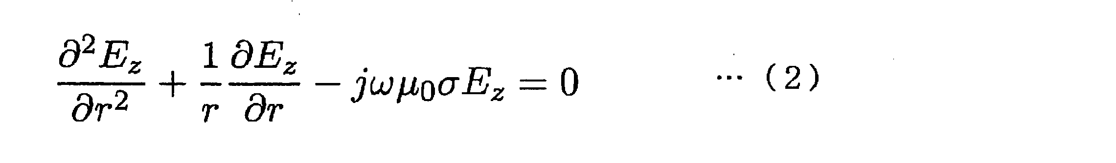
ただし、μ0は真空中の透磁率を表す。また、磁界Hθはθ方向成分のみを有し、次のように与えられる。
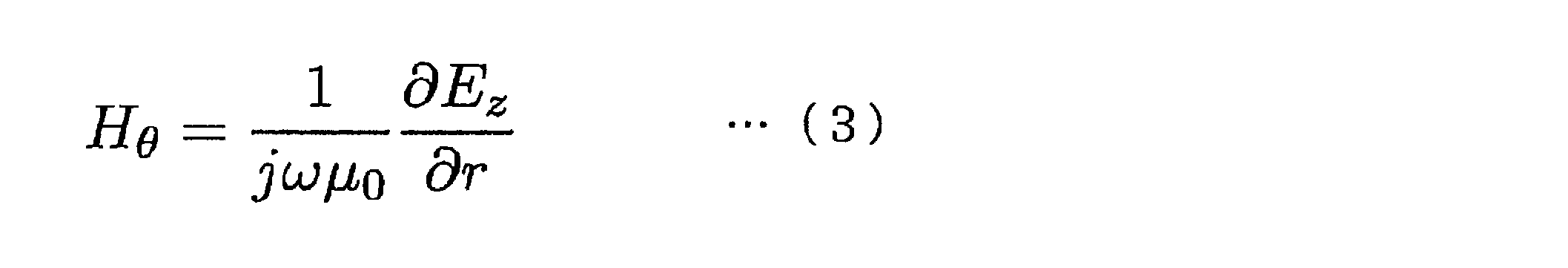
However, μ 0 represents the magnetic permeability in vacuum. The magnetic field Hθ has only a θ direction component and is given as follows.
ここで、

here,
をおくと、波動方程式(2)の解は次のようにおくことができる。

, The solution of the wave equation (2) can be set as follows.
ただし、Jν(z)は第1種Bessel関数を表し、


Where J ν (z) represents the first kind Bessel function,

となる。ただし、

It becomes. However,
である。ここで、
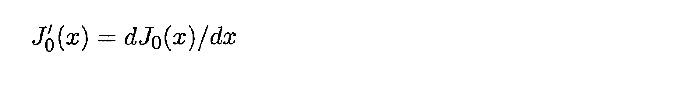

It is. here,


ただし、


However,
一方、図6に示す導線に流れ込むパワーフローはPoyntingベクトルより次式(15)のように計算される。
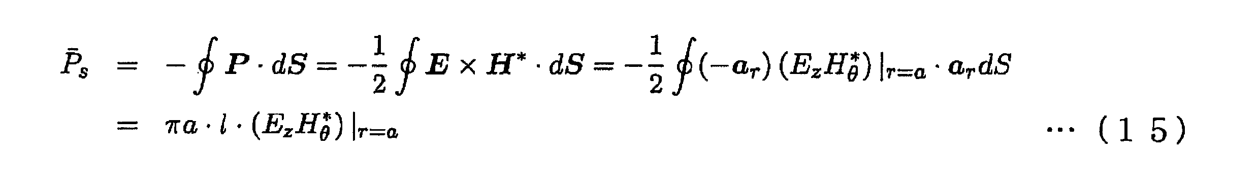
On the other hand, the power flow flowing into the conducting wire shown in FIG. 6 is calculated by the following equation (15) from the Poynting vector.
ここで、


here,

ここで、

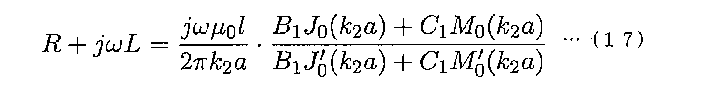
here,
したがって、表皮効果による単位長さ当たりの交流抵抗は、次のように与えられる。

Therefore, the AC resistance per unit length due to the skin effect is given as follows.
ただし、

However,

となり、式(18)は、

Equation (18) becomes
となる。
It becomes.

ここで、H=∇×Aを満たす磁気ポテンシャル

Here, magnetic potential satisfying H = ∇ × A
を導入すると、外部ポテンシャル

Introducing external potential
は式(22)の磁界を与える。
Gives the magnetic field of equation (22).

ただし、μ0は真空中の透磁率を表す。
However, μ 0 represents the magnetic permeability in vacuum.

各境界で磁界の接線成分(Hθ)と磁束密度の法線成分(μ0Hr)が連続になる境界条件により、

Due to the boundary condition where the tangential component (H θ ) of the magnetic field and the normal component (μ 0 Hr) of the magnetic flux density are continuous at each boundary,
となる。ただし、

It becomes. However,
である。ここで、
である。
It is. here,
It is.

また、電界Ezは次のように得られる。

Moreover, the electric field Ez is obtained as follows.
図8に示す導線表面から導線内部に入り込むパワーフローは次式(38)のように計算される。
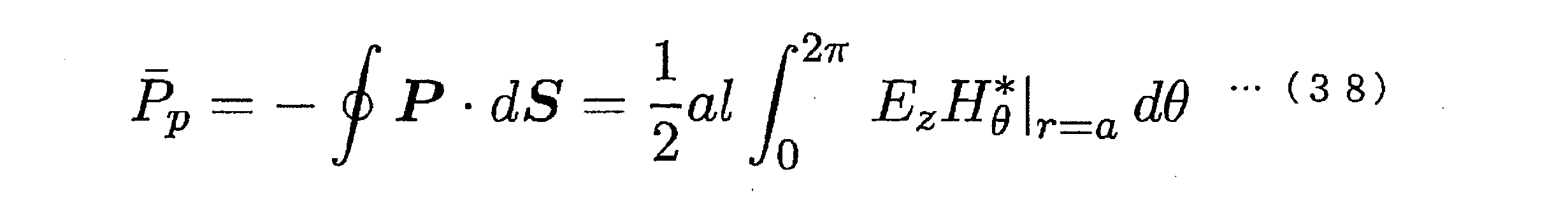
The power flow entering the inside of the conducting wire from the surface of the conducting wire shown in FIG. 8 is calculated as the following equation (38).
ただし、


However,

ただし、
However,
である。導線の損失PLは、次のように求められる。

It is. The loss P L of the conducting wire is obtained as follows.
導線が一層構造の場合、σ1=σ2,式(34)及び式(35)より、

When the conducting wire has a single -layer structure, σ 1 = σ 2 , from Equation (34) and Equation (35),


本発明の第1の実施の形態に係る電線の設計装置は、図16に示すように、中央処理装置(CPU)110、記憶装置111、入力装置112及び出力装置113を備える。 <Electric wire design equipment>
As illustrated in FIG. 16, the electric wire design apparatus according to the first embodiment of the present invention includes a central processing unit (CPU) 110, a
本発明の第1の実施の形態に係る電線の設計装置を用いた設計方法を含む高周波電線の製造方法の一例を、図17のフローチャートを用いて説明する。なお、ここではCCA線の製造方法を説明するが、これに特に限定されないことは勿論である。 <Manufacturing method of high frequency electric wire>
An example of the manufacturing method of the high frequency electric wire containing the design method using the electric wire design apparatus which concerns on the 1st Embodiment of this invention is demonstrated using the flowchart of FIG. In addition, although the manufacturing method of a CCA line is demonstrated here, of course, it is not specifically limited to this.
図17に示した一連の手順、即ち:(イ)特定の周波数帯域における電線の候補となる導体部11の近接効果による交流抵抗、及び特定の周波数帯域における基準とするCu線の近接効果による交流抵抗をそれぞれ計算するステップ;(ロ)基準とするCu線の近接効果による交流抵抗に対する導体部の近接効果による交流抵抗の比を計算するステップ;(ハ)比に基づいて候補を電線に適用可能か判定するステップ等は、図17と等価なアルゴリズムのプログラムにより、図16に示した電線の設計装置を制御して実行できる。 <Wire design program>
A series of procedures shown in FIG. 17, namely: (a) AC resistance due to proximity effect of
<電線の構造>
本発明の第2の実施の形態に係る電線は、特定の周波数帯域で使用される電線であって、図18に示すように、アルミニウム(Al)又はアルミニウム合金からなる中心導体21と、中心導体21を被覆する銅(Cu)からなる被覆層22とを備えるCCA線である。本発明の第2の実施の形態に係る電線は、電線の交流抵抗と、電線と同じ線径を有するCu線の交流抵抗とがそれぞれ一致する第1の周波数及び第2の周波数の間に規定され、且つ電線の交流抵抗がCu線の交流抵抗よりも大きい周波数帯域内に、特定の周波数帯域が収まる。 (Second Embodiment)
<Wire structure>
The electric wire according to the second embodiment of the present invention is an electric wire used in a specific frequency band, and as shown in FIG. 18, a
本発明の第2の実施の形態に係る電線の設計装置は、図23に示すように、中央処理装置(CPU)210、記憶装置211、入力装置212及び出力装置213を備える。 <Electric wire design equipment>
As shown in FIG. 23, the electric wire design apparatus according to the second embodiment of the present invention includes a central processing unit (CPU) 210, a
本発明の第2の実施の形態に係る電線の設計装置を用いた電線の設計方法を含むCCA素線の製造方法の一例を、図24のフローチャートを用いて説明する。 <Manufacturing method of CCA wire>
An example of a method for producing a CCA strand including an electric wire design method using the electric wire design apparatus according to the second embodiment of the present invention will be described with reference to the flowchart of FIG.
図24に示した一連の手順、即ち:(イ)複数の周波数に応じて、CCA線の交流抵抗及びCCA線と同じ線径を有するCu線の交流抵抗を複数の線径毎に計算するステップ;(ロ)複数の線径毎に、CCA線の交流抵抗とCu線の交流抵抗が一致し、且つ互いの間でCCA線の交流抵抗がCu線の交流抵抗よりも小さくなる第1の周波数f11,f21,f31及び第2の周波数f12,f22,f32を抽出するステップ;及び(ハ)複数の線径のうち、抽出された第1の周波数f11,f21,f31及び第2の周波数f12,f22,f32の間に規定される周波数帯域B1,B2,B3が、CCA線を使用する特定の周波数帯域内に収まるような第1の周波数f11,f21,f31及び第2の周波数f12,f22,f32に対応する線径を抽出するステップ;等は、図24と等価なアルゴリズムのプログラムにより、図23に示した電線の設計装置を制御して実行出来る。 <Design program>
A series of procedures shown in FIG. 24, that is: (a) calculating the AC resistance of the CCA line and the AC resistance of the Cu line having the same diameter as that of the CCA line for each of a plurality of frequencies. (B) a first frequency at which the AC resistance of the CCA line and the AC resistance of the Cu line coincide with each other and the AC resistance of the CCA line is smaller than the AC resistance of the Cu line between each other; extracting f11, f21, f31 and second frequencies f12, f22, f32; and (c) extracting a first frequency f11, f21, f31 and a second frequency f12, out of a plurality of wire diameters. The first frequencies f11, f21, f31 and the second frequencies f12, f22, f2 and f22 such that the frequency bands B1, B2, B3 defined between f22 and f32 fall within a specific frequency band using the CCA line. f32 Step extracting a wire diameter of, or the like, by 24 equivalent algorithm program, wire design device control to be executed as shown in FIG. 23.
次に、本発明の第2の実施の形態に係る電気モータについて説明する。インバータ装置などを用いて回転速度やトルクを調整する電気モータは高効率であり、鉄道車両や電気自動車の駆動、家電分野でインバータエアコンなど広範囲の分野に使われている。 <Electric motor>
Next, an electric motor according to a second embodiment of the present invention will be described. An electric motor that adjusts rotational speed and torque using an inverter device or the like is highly efficient, and is used in a wide range of fields such as inverter air conditioners in the drive of railway vehicles and electric vehicles, and home appliances.
Rac=Rs+α2Pp …(49)
ただし、Rs(単位はΩ/m)は表皮効果による単位長さ当りの高周波抵抗であり、Pp(単位はΩ・m)は近接効果による単位長さ当りの高周波損失であり、α(単位は1/m)はコイルの形状に依存する形状因子(構造因子)である。αは、ほぼ周波数に依存しない定数であり、コイルの巻き線が密に巻けば大きくなり、また巻く導線が長いほど大きくなる。αは必要とする電気モータの出力などに依存するが、変化するものである。
R ac = R s + α 2 P p (49)
Where R s (unit: Ω / m) is the high frequency resistance per unit length due to the skin effect, and P p (unit: Ω · m) is the high frequency loss per unit length due to the proximity effect, α ( The unit is 1 / m) is a shape factor (structure factor) depending on the shape of the coil. α is a constant substantially independent of frequency, and becomes larger when the coil winding is densely wound, and becomes larger as the winding wire is longer. α varies depending on the required output of the electric motor and the like.

本発明の第2の実施の形態の第1の実施例に係る電気モータ(三相交流同期モータ)は、図25に示すように、円心状に配置された複数の鉄心221と、Al線又はCCA線からなる電線222が複数の鉄心221に巻かれた複数のコイル223と、複数のコイル223に電流を印加することにより回転する回転子224とを備える。複数の鉄心221、複数のコイル223及びコイル保持部20等により固定子が構成される。 <First embodiment>
As shown in FIG. 25, the electric motor (three-phase AC synchronous motor) according to the first example of the second embodiment of the present invention includes a plurality of
本発明の第2の実施の形態の第2の実施例に係る電気モータ(三相交流同期モータ)は、図40に示すように、円心状に配置された複数の鉄心221と、Al線又はCCA線からなる電線222が複数の鉄心221に巻かれた複数のコイル223と、複数のコイル223に電流を印加することにより回転する回転子224とを備える。 <Second embodiment>
As shown in FIG. 40, an electric motor (three-phase AC synchronous motor) according to a second example of the second embodiment of the present invention includes a plurality of
本発明の第2の実施の形態の第3の実施例に係る電気モータ(三相交流同期モータ)は、図49に示すように、複数の鉄心221と、Al線又はCCA線からなる電線222が複数の鉄心221に巻かれた複数のコイル223と、複数のコイル223に電流を印加することにより回転する回転子224とを備える。 <Third embodiment>
As shown in FIG. 49, an electric motor (three-phase AC synchronous motor) according to a third example of the second embodiment of the present invention has a plurality of
<電線の構造>
本発明の第3の実施の形態に係る電線は、図58(a)に示すように、銅よりも体積抵抗率が高い材料からなる導体部31を備える。本発明の第3の実施の形態に係る電線においては、電線の交流抵抗と、電線と同じ線径を有するCu線の交流抵抗とがそれぞれ一致し、互いの間において電線の交流抵抗がCu線の交流抵抗よりも小さい第1の周波数及び第1の周波数より大きい第2の周波数のうち、第2の周波数が特定の周波数帯域の上限値以上となるように、導体部31の体積抵抗率を断面積で除した単位長さ当たりの直流抵抗値が規定されている。 (Third embodiment)
<Wire structure>
As shown in FIG. 58 (a), the electric wire according to the third embodiment of the present invention includes a
f2=10(0.925×log Rdc + 2.24) …(53)
本発明の第3の実施の形態に係る電線は、式(53)を用いて、電線が使用される特定の周波数帯域の上限値以上の第2の周波数を有するように、導体部31の基準直流抵抗値が規定されている。即ち、その基準直流抵抗値となるように、導体部31の体積抵抗率、断面積、材料、形状及び線径等が規定されている。
f 2 = 10 (0.925 × log Rdc + 2.24) (53)
The electric wire according to the third embodiment of the present invention uses the formula (53), and the reference of the
0.7×10(0.925×log Rdc + 2.24)≦f2≦1.3×10(0.925×log Rdc + 2.24) …(54)
の関係で規定しても良い。この結果、基準直流抵抗値に実効的な範囲で幅を持たせることができ、基準直流抵抗値を規定する導体部31の体積抵抗率、断面積、材料、形状及び線径等の設計自由度を向上させることができる。 Further, FIG. 61 shows two broken lines of 0.7 times and 1.3 times of the regression line shown by the solid line. In the third embodiment of the present invention, in consideration of the variation of about ± 30% of the regression line, the reference DC resistance value is defined within the bandwidth range between the two broken lines shown in FIG. May be. That is, the reference DC resistance value R dc of the high-frequency electric wire according to the third embodiment of the present invention is set to a second frequency f 2 ,
0.7 × 10 (0.925 × log Rdc + 2.24) ≦ f 2 ≦ 1.3 × 10 (0.925 × log Rdc + 2.24) (54)
You may prescribe in relation to. As a result, the reference DC resistance value can be widened in an effective range, and the degree of freedom in designing the volume resistivity, cross-sectional area, material, shape, wire diameter, etc. of the
f0≦10(0.925×log Rdc + 2.24) …(55)
を満たすように規定しても良い。この結果、第2の周波数を特定の周波数帯域の上限値以上に設定できるとともに、式(55)の関係を満たす範囲で基準直流抵抗値を規定することができるので、基準直流抵抗値を規定する導体部31の体積抵抗率、断面積、材料、形状及び線径等の設計自由度を向上させることができる。 Further, the reference DC resistance value R dc is set to an upper limit value f 0 of a specific frequency band,
f 0 ≦ 10 (0.925 × log Rdc + 2.24) (55)
You may prescribe | regulate so that it may satisfy | fill. As a result, the second frequency can be set to be equal to or higher than the upper limit value of the specific frequency band, and the reference DC resistance value can be specified in a range satisfying the relationship of Expression (55), so that the reference DC resistance value is specified. The degree of freedom in design such as volume resistivity, cross-sectional area, material, shape, and wire diameter of the
本発明の第3の実施の形態に係る電線の設計装置は、図63に示すように、中央処理装置(CPU)310、記憶装置311、入力装置312及び出力装置313を備える。 <Electric wire design equipment>
As illustrated in FIG. 63, the electric wire design apparatus according to the third embodiment of the present invention includes a central processing unit (CPU) 310, a
本発明の第3の実施の形態に係る電線の設計装置を用いた設計方法を含む高周波電線の製造方法の一例を、図64のフローチャートを用いて説明する。なお、ここではCCA線の製造方法を説明するが、これに特に限定されないことは勿論である。 <Manufacturing method of high frequency electric wire>
An example of the manufacturing method of the high frequency electric wire including the design method using the electric wire design apparatus according to the third embodiment of the present invention will be described with reference to the flowchart of FIG. In addition, although the manufacturing method of a CCA line is demonstrated here, of course, it is not specifically limited to this.
図64に示した一連の手順、即ち:(イ)高周波電線の材料、形状及び線径等の組み合わせからなる線種毎に単位長さ当たりの直流抵抗値を計算するステップ;(ロ)電線の交流抵抗と、電線と同じ線径を有するCu線の交流抵抗とがそれぞれ一致し、互いの間において電線の交流抵抗がCu線の交流抵抗よりも小さい第1の周波数及び該第1の周波数より大きい第2の周波数のうち、第2の周波数を特定の周波数帯域の上限値以上の値に設定するステップ;(ハ)第2の周波数から、基準直流抵抗値を計算するステップ;(ニ)基準直流抵抗値に応じて電線の種類を決定するステップ等は、図64と等価なアルゴリズムのプログラムにより、図63に示した電線の設計装置を制御して実行出来る。 <Wire design program>
A series of procedures shown in FIG. 64, that is: (a) a step of calculating a direct current resistance value per unit length for each wire type composed of a combination of the material, shape, wire diameter, etc. of the high-frequency wire; The AC resistance and the AC resistance of the Cu wire having the same wire diameter as the electric wire match each other, and the AC frequency of the electric wire is smaller than the AC resistance of the Cu wire between the first frequency and the first frequency. A step of setting the second frequency to a value greater than or equal to an upper limit value of a specific frequency band among the large second frequencies; (c) calculating a reference DC resistance value from the second frequency; The step of determining the type of the electric wire according to the direct current resistance value can be executed by controlling the electric wire designing apparatus shown in FIG. 63 by the program of the algorithm equivalent to FIG.
<高周波電線の構造>
本発明の第4の実施の形態に係る高周波電線は、10kHz~1MHz程度の周波数帯域で使用される電線であって、図65に示すように、銅よりも体積抵抗率の高い銅合金を導体部41とする。 (Fourth embodiment)
<Structure of high frequency electric wire>
The high-frequency electric wire according to the fourth embodiment of the present invention is an electric wire used in a frequency band of about 10 kHz to 1 MHz, and as shown in FIG. 65, a copper alloy having a higher volume resistivity than copper is used as a conductor. This is
第1の実施例として、本発明の第4の実施の形態に係る高周波電線の磁界強度分布及び損失分布の測定結果を説明する。図69及び図70に、比較例として、外部磁界強度を1A/mmとして、半径0.2mmのCu線に100kHzを印加したときのCu線のy軸に沿った磁界強度分布及び損失分布をそれぞれ示す。図71及び図72に、本発明の第4の実施の形態に係る高周波電線として、外部磁界強度を1A/mmとして、半径0.2mmのケイ青銅線に100kHzを印加したときのケイ青銅線のy軸に沿った磁界強度分布及び損失分布をそれぞれ示す。図71と図69とを対比すると、ケイ青銅線の表層付近の磁界強度がCu線の場合よりも弱いことが分かる。また、図72と図70とを対比すると、ケイ青銅線の渦電流による損失がCu線の場合と比較して小さくなることが分かる。 <First embodiment>
As a first example, the measurement results of the magnetic field strength distribution and loss distribution of the high-frequency electric wire according to the fourth embodiment of the present invention will be described. 69 and 70, as a comparative example, the magnetic field strength distribution and the loss distribution along the y-axis of the Cu wire when the external magnetic field strength is 1 A / mm and 100 kHz is applied to the Cu wire having a radius of 0.2 mm, respectively. Show. 71 and 72, as a high-frequency electric wire according to the fourth embodiment of the present invention, an external magnetic field strength of 1 A / mm and a quartz bronze wire when 100 kHz is applied to a quartz bronze wire having a radius of 0.2 mm. The magnetic field strength distribution and the loss distribution along the y-axis are respectively shown. When FIG. 71 and FIG. 69 are compared, it can be seen that the magnetic field intensity in the vicinity of the surface layer of the quartz bronze wire is weaker than that of the Cu wire. Moreover, when FIG. 72 is compared with FIG. 70, it turns out that the loss by the eddy current of a quartz bronze wire becomes small compared with the case of Cu wire.
第2の実施例として、図77に、外部磁界強度Hを1(A/mm)として計算した本発明の第4の実施の形態に係る黄銅線、リン青銅線、ケイ青銅線及び比較例に係るCu線の交流抵抗(近接効果成分)を示す。図77から、所定の周波数帯域において、黄銅線、リン青銅線、ケイ青銅線の交流抵抗がCu線の交流抵抗よりも小さくなることが分かる。 <Second embodiment>
As a second example, FIG. 77 shows a brass wire, a phosphor bronze wire, a quartz bronze wire and a comparative example according to the fourth embodiment of the present invention calculated with an external magnetic field strength H of 1 (A / mm). The AC resistance (proximity effect component) of the Cu wire is shown. From FIG. 77, it can be seen that the AC resistance of the brass wire, phosphor bronze wire, and silicon bronze wire is smaller than the AC resistance of the Cu wire in a predetermined frequency band.
第3の実施例として、本発明の第4の実施の形態に係る高周波電線である黄銅線、リン青銅線、ケイ青銅線及び比較例に係るCu線について、直径0.4mmの素線を14本用いて、80ターンでリアクトルをそれぞれ作製した。リアクトルの交流抵抗を1本当たりの単位長さで表した測定結果を図9に示す。図9において、黄銅線、リン青銅線、ケイ青銅線の交流抵抗がCu線の交流抵抗よりも、小さくなることが分かる。また、図77に示した素線の場合と比較すると、リアクトルの場合の交流抵抗の抑制効果がより大きいことが分かる。 <Third embodiment>
As a 3rd Example, about the brass wire which is the high frequency electric wire which concerns on the 4th Embodiment of this invention, a phosphor bronze wire, a quartz bronze wire, and the Cu wire which concerns on a comparative example, the wire with a diameter of 0.4 mm is 14 Using this, each reactor was produced in 80 turns. The measurement result which represented the alternating current resistance of the reactor by the unit length per one is shown in FIG. In FIG. 9, it can be seen that the AC resistance of the brass wire, phosphor bronze wire, and silica bronze wire is smaller than the AC resistance of the Cu wire. Further, it can be seen that the effect of suppressing the AC resistance in the case of the reactor is larger than that in the case of the strand shown in FIG.
第4の実施例として、本発明の第4の実施の形態に係る黄銅線及び比較例に係るCu線について、図10に示すように直径0.4mm、長さ6.6mの素線を55本用いて、17ターンでリッツ線構造とし、IH調理器用の磁場発生コイルを作製し、それらについて特性確認試験を行った。試験結果を図11及び図12に示す。IH調理器には、一般的に20kHz~60kHz程度の高周波電流が使用されるが、20kHz~60kHz程度を含む周波数帯域では、黄銅線の交流抵抗がCu線の交流抵抗よりも小さくなるのが分かる。 <Fourth embodiment>
As a fourth example, for the brass wire according to the fourth embodiment of the present invention and the Cu wire according to the comparative example, a wire having a diameter of 0.4 mm and a length of 6.6 m as shown in FIG. Using this, a 17-turn Litz wire structure was used, magnetic field generating coils for an IH cooker were produced, and a characteristic confirmation test was performed on them. The test results are shown in FIGS. A high frequency current of about 20 kHz to 60 kHz is generally used for an IH cooker, but it can be seen that the AC resistance of the brass wire is smaller than the AC resistance of the Cu wire in a frequency band including about 20 kHz to 60 kHz. .
次に、本発明の第4の実施の形態に係る高周波電線の製造方法の一例を説明する。なお、以下に示す製造方法は一例であり特に限定されるものではない。本発明の第4の実施の形態に係る高周波電線は種々の製造方法により製造することが可能である。 <Manufacturing method of high frequency electric wire>
Next, an example of the manufacturing method of the high frequency electric wire which concerns on the 4th Embodiment of this invention is demonstrated. In addition, the manufacturing method shown below is an example and is not specifically limited. The high frequency electric wire according to the fourth embodiment of the present invention can be manufactured by various manufacturing methods.
上記のように、本発明は実施の形態によって記載したが、この開示の一部をなす論述及び図面はこの発明を限定するものであると理解すべきではない。この開示から当業者には様々な代替実施の形態、実施例及び運用技術が明らかとなろう。 (Other embodiments)
As described above, the present invention has been described according to the embodiment. However, it should not be understood that the description and drawings constituting a part of this disclosure limit the present invention. From this disclosure, various alternative embodiments, examples and operational techniques will be apparent to those skilled in the art.
Claims (16)
- 銅よりも体積抵抗率が高い材料からなる導体部を備える電線であって、
前記電線が使用される周波数帯域において、基準とする銅線の交流抵抗に対する前記導体部の交流抵抗の比が1未満となるように前記導体部の体積抵抗率が規定されていることを特徴とする電線。 An electric wire comprising a conductor portion made of a material having a higher volume resistivity than copper,
The volume resistivity of the conductor is defined so that the ratio of the AC resistance of the conductor to the AC resistance of a copper wire as a reference is less than 1 in the frequency band in which the wire is used. Electric wire to be used. - 前記基準とする銅線が、前記導体部と同じ線径を有することを特徴とする請求項1に記載の電線。 The electric wire according to claim 1, wherein the reference copper wire has the same wire diameter as the conductor portion.
- 前記電線の交流抵抗と、前記基準とする銅線の交流抵抗とがそれぞれ一致し、互いの間において前記電線の交流抵抗が前記基準とする銅線の交流抵抗よりも小さい第1の周波数及び該第1の周波数より大きい第2の周波数のうち、前記第2の周波数が前記電線が使用される周波数帯域の上限値以上となるように、前記導体部の体積抵抗率を断面積で除した単位長さ当たりの直流抵抗値が規定されていることを特徴とする請求項1又は2に記載の電線。 The AC resistance of the electric wire and the AC resistance of the copper wire used as the reference match each other, and the AC frequency of the electric wire between the first frequency is smaller than the AC resistance of the copper wire used as the reference, and the first frequency The unit obtained by dividing the volume resistivity of the conductor portion by the cross-sectional area so that the second frequency is equal to or higher than the upper limit value of the frequency band in which the electric wire is used among the second frequencies larger than the first frequency. The electric wire according to claim 1 or 2, wherein a direct current resistance value per length is defined.
- 前記直流抵抗値は、前記直流抵抗値をRdc、前記第2の周波数をf2として、
0.7×10(0.925×log Rdc + 2.24)≦f2≦1.3×10(0.925×log Rdc + 2.24)
の関係で規定されていることを特徴とする請求項3に記載の電線。 The DC resistance value is defined as Rdc as the DC resistance value and f2 as the second frequency.
0.7 × 10 (0.925 × log Rdc + 2.24) ≦ f 2 ≦ 1.3 × 10 (0.925 × log Rdc + 2.24)
The electric wire according to claim 3, wherein the electric wire is defined by the relationship: - 前記導体部が、黄銅、リン青銅、ケイ青銅、銅・ベリリウム合金及び銅・ニッケル・ケイ素合金から選ばれる銅合金、並びに銅被覆アルミニウムのいずれかからなることを特徴とする請求項1~4のいずれか1項に記載の電線。 The conductor portion is made of any one of brass, phosphor bronze, silica bronze, a copper alloy selected from a copper / beryllium alloy and a copper / nickel / silicon alloy, and copper-coated aluminum. An electric wire given in any 1 paragraph.
- 前記電線が使用される周波数帯域が、基準周波数から20次までの高調波の周波数を含むことを特徴とする請求項1~5のいずれか1項に記載の電線。 The electric wire according to any one of claims 1 to 5, wherein a frequency band in which the electric wire is used includes harmonic frequencies from a reference frequency to the 20th order.
- 前記電線が使用される周波数帯域が、10kHz~1MHzであることを特徴とする請求項1~6のいずれか1項に記載の電線。 The electric wire according to any one of claims 1 to 6, wherein a frequency band in which the electric wire is used is 10 kHz to 1 MHz.
- 電線を素線として用いたコイルであって、
前記電線が銅よりも体積抵抗率が高い材料からなる導体部を備え、
前記電線が使用される周波数帯域において、基準とする銅線の交流抵抗に対する前記導体部の交流抵抗の比が1未満となるように前記導体部の体積抵抗率が規定されていることを特徴とするコイル。 A coil using an electric wire as an element wire,
The electric wire comprises a conductor portion made of a material having a higher volume resistivity than copper,
The volume resistivity of the conductor is defined so that the ratio of the AC resistance of the conductor to the AC resistance of a copper wire as a reference is less than 1 in the frequency band in which the wire is used. Coil to play. - 前記基準とする銅線が、前記導体部と同じ線径を有することを特徴とする請求項8に記載のコイル。 The coil according to claim 8, wherein the reference copper wire has the same wire diameter as the conductor portion.
- 前記電線の交流抵抗と、前記基準とする銅線の交流抵抗とがそれぞれ一致し、互いの間において前記電線の交流抵抗が前記基準とする銅線の交流抵抗よりも小さい第1の周波数及び該第1の周波数より大きい第2の周波数のうち、前記第2の周波数が前記電線が使用される周波数帯域の上限値以上となるように、前記導体部の体積抵抗率を断面積で除した単位長さ当たりの直流抵抗値が規定されていることを特徴とする請求項8又は9に記載のコイル。 The AC resistance of the electric wire and the AC resistance of the copper wire used as the reference match each other, and the AC resistance of the electric wire between them is smaller than the AC resistance of the copper wire used as the reference, and the first frequency A unit obtained by dividing the volume resistivity of the conductor portion by the cross-sectional area so that the second frequency is equal to or higher than the upper limit value of the frequency band in which the electric wire is used among the second frequencies larger than the first frequency. The coil according to claim 8 or 9, wherein a direct current resistance value per length is defined.
- 前記直流抵抗値は、前記直流抵抗値をRdc、前記第2の周波数をf2として、
0.7×10(0.925×log Rdc + 2.24)≦f2≦1.3×10(0.925×log Rdc + 2.24)
の関係で規定されていることを特徴とする請求項10に記載のコイル。 The DC resistance value is defined as Rdc as the DC resistance value and f2 as the second frequency.
0.7 × 10 (0.925 × log Rdc + 2.24) ≦ f 2 ≦ 1.3 × 10 (0.925 × log Rdc + 2.24)
The coil according to claim 10, which is defined by the relationship: - 前記導体部が、黄銅、リン青銅、ケイ青銅、銅・ベリリウム合金及び銅・ニッケル・ケイ素合金から選ばれる銅合金、並びに銅被覆アルミニウムのいずれかからなることを特徴とする請求項8~11のいずれか1項に記載のコイル。 The conductor portion is made of any one of brass, phosphor bronze, quartz bronze, a copper alloy selected from a copper-beryllium alloy and a copper-nickel-silicon alloy, and copper-coated aluminum. The coil according to any one of the above.
- 前記電線が使用される周波数帯域が、基準周波数から20次までの高調波の周波数を含むことを特徴とする請求項8~12のいずれか1項に記載のコイル。 The coil according to any one of claims 8 to 12, wherein a frequency band in which the electric wire is used includes harmonic frequencies from a reference frequency to the 20th order.
- 前記電線が使用される周波数帯域が、10kHz~1MHzであることを特徴とする請求項8~13のいずれか1項に記載のコイル。 The coil according to any one of claims 8 to 13, wherein a frequency band in which the electric wire is used is 10 kHz to 1 MHz.
- 銅よりも体積抵抗率が高い材料からなる電線の設計装置であって、
前記電線が使用される周波数帯域における前記電線の候補となる導体部の交流抵抗、及び基準とする銅線の交流抵抗をそれぞれ計算する抵抗計算部と、
前記基準とする銅線の近接効果による交流抵抗に対する前記導体部の近接効果による交流抵抗の比を計算する比計算部と、
前記比が1未満となる場合に、前記候補が前記電線に適用可能と判定する判定部
とを備えることを特徴とする電線の設計装置。 A wire design device made of a material having a higher volume resistivity than copper,
A resistance calculator for calculating the AC resistance of the conductor part that is a candidate for the electric wire in the frequency band in which the electric wire is used, and the AC resistance of the copper wire as a reference;
A ratio calculation unit for calculating a ratio of the AC resistance due to the proximity effect of the conductor part to the AC resistance due to the proximity effect of the copper wire as the reference;
An electric wire design apparatus comprising: a determination unit that determines that the candidate is applicable to the electric wire when the ratio is less than 1. - 円心状に配置された複数の鉄心と、
アルミニウム線、又はアルミニウム若しくはアルミニウム合金からなる中心導体と、前記中心導体を被覆する銅からなる被覆層とを備える電線が前記複数の鉄心に巻かれた複数のコイルと、
前記複数のコイルに交流電流を印加することにより回転する回転子
とを備え、
前記コイルの交流抵抗が、前記基準とする銅線で巻いたコイルの交流抵抗よりも小さくなる第1の周波数及び該第1の周波数より高い第2の周波数の間に収まるように、前記コイルに印加する交流電流の周波数がインバータ方式により制御されることを特徴とする電気モータ。 A plurality of iron cores arranged in a circle,
A plurality of coils in which an electric wire comprising an aluminum wire or a central conductor made of aluminum or an aluminum alloy and a coating layer made of copper covering the central conductor is wound around the plurality of iron cores;
A rotor that rotates by applying an alternating current to the plurality of coils,
The coil has an AC resistance that falls between the first frequency that is smaller than the AC resistance of the coil wound with the reference copper wire and the second frequency that is higher than the first frequency. An electric motor characterized in that the frequency of an alternating current to be applied is controlled by an inverter system.
Priority Applications (9)
| Application Number | Priority Date | Filing Date | Title |
|---|---|---|---|
| EP11818022.3A EP2608222B1 (en) | 2010-08-20 | 2011-07-21 | Method of manufacturing a high-frequency electric wire |
| BR112013003939A BR112013003939A2 (en) | 2010-08-20 | 2011-07-21 | electric wire, coil, electrical wire designing apparatus, and electric motor |
| KR1020137010312A KR101284075B1 (en) | 2010-08-20 | 2011-07-21 | Electric wire, coil, device for designing electric wire, and electric motor |
| KR1020137006940A KR101284074B1 (en) | 2010-08-20 | 2011-07-21 | Electric wire, coil, device for designing electric wire, and electric motor |
| JP2011550162A JP5061259B2 (en) | 2010-08-20 | 2011-07-21 | Electric wires and coils |
| CN201180040420.7A CN103098144B (en) | 2010-08-20 | 2011-07-21 | The design apparatus of electric wire, coil, electric wire and motor |
| US13/770,445 US8866019B2 (en) | 2010-08-20 | 2013-02-19 | Electric wire, coil, device for designing electric wire, and electric motor |
| US13/874,852 US8723387B2 (en) | 2010-08-20 | 2013-05-01 | Electric wire, coil, device for designing electric wire, and electric motor |
| US14/290,444 US9425662B2 (en) | 2010-08-20 | 2014-05-29 | Electric wire, coil, device for designing electric wire, and electric motor |
Applications Claiming Priority (12)
| Application Number | Priority Date | Filing Date | Title |
|---|---|---|---|
| JP2010185637 | 2010-08-20 | ||
| JP2010185636 | 2010-08-20 | ||
| JP2010185635 | 2010-08-20 | ||
| JP2010-185637 | 2010-08-20 | ||
| JP2010-185636 | 2010-08-20 | ||
| JP2010-185638 | 2010-08-20 | ||
| JP2010185638 | 2010-08-20 | ||
| JP2010-185635 | 2010-08-20 | ||
| JP2010-209651 | 2010-09-17 | ||
| JP2010209651 | 2010-09-17 | ||
| JP2010283809 | 2010-12-20 | ||
| JP2010-283809 | 2010-12-20 |
Related Child Applications (3)
| Application Number | Title | Priority Date | Filing Date |
|---|---|---|---|
| US13770445 A-371-Of-International | 2011-07-21 | ||
| US13/770,445 Continuation US8866019B2 (en) | 2010-08-20 | 2013-02-19 | Electric wire, coil, device for designing electric wire, and electric motor |
| US14/290,444 Division US9425662B2 (en) | 2010-08-20 | 2014-05-29 | Electric wire, coil, device for designing electric wire, and electric motor |
Publications (1)
| Publication Number | Publication Date |
|---|---|
| WO2012023378A1 true WO2012023378A1 (en) | 2012-02-23 |
Family
ID=45605039
Family Applications (1)
| Application Number | Title | Priority Date | Filing Date |
|---|---|---|---|
| PCT/JP2011/066563 WO2012023378A1 (en) | 2010-08-20 | 2011-07-21 | Electric wire, coil, device for designing electric wire, and electric motor |
Country Status (7)
| Country | Link |
|---|---|
| US (3) | US8866019B2 (en) |
| EP (2) | EP2608222B1 (en) |
| JP (4) | JP5061259B2 (en) |
| KR (2) | KR101284074B1 (en) |
| CN (2) | CN103236752B (en) |
| BR (1) | BR112013003939A2 (en) |
| WO (1) | WO2012023378A1 (en) |
Cited By (5)
| Publication number | Priority date | Publication date | Assignee | Title |
|---|---|---|---|---|
| JP2012151127A (en) * | 2010-08-20 | 2012-08-09 | Fujikura Ltd | Method of manufacturing electric wire and method of designing electric wire |
| WO2013051665A1 (en) * | 2011-10-05 | 2013-04-11 | 矢崎総業株式会社 | Specification determination assistance method for alternating current line and specification determination assistance device, as well as specification determination assistance program |
| WO2014148430A1 (en) | 2013-03-18 | 2014-09-25 | 株式会社フジクラ | Wire and coil |
| WO2015083456A1 (en) | 2013-12-02 | 2015-06-11 | 株式会社フジクラ | High-frequency electrical wire and coil |
| CN105428158A (en) * | 2015-10-31 | 2016-03-23 | 成都海沃斯电气技术有限公司 | AC contactor excitation coil and driving mechanism thereof |
Families Citing this family (15)
| Publication number | Priority date | Publication date | Assignee | Title |
|---|---|---|---|---|
| DE102009021444A1 (en) * | 2009-05-15 | 2010-11-25 | Tyco Electronics Belgium Ec Bvba | Magnetoelectronic angle sensor, in particular reluctance resolver |
| WO2013042671A1 (en) * | 2011-09-22 | 2013-03-28 | 株式会社フジクラ | Electric wire and coil |
| CN203078469U (en) * | 2012-01-20 | 2013-07-24 | 德昌电机(深圳)有限公司 | Safety belt tongue plate actuator |
| CN104283351A (en) * | 2013-07-02 | 2015-01-14 | 丹佛斯(天津)有限公司 | Stator, three-phase induction motor and compressor |
| US20150061441A1 (en) * | 2013-08-29 | 2015-03-05 | Regal Beloit America, Inc. | Electric machine and associated method |
| US20160099622A1 (en) * | 2014-10-07 | 2016-04-07 | Hamilton Sundstrand Corporation | Hybrid Conductor for Generator Stator Winding |
| US20170163141A1 (en) * | 2015-12-08 | 2017-06-08 | Mary Fales | System, method, and apparatus for energy recapture using induction |
| US10776552B2 (en) * | 2016-12-05 | 2020-09-15 | Synopsys, Inc. | Nano-wire resistance model |
| CN106705827B (en) * | 2017-02-23 | 2019-03-12 | 苏州热工研究院有限公司 | The calculation method of conducting wire optimum diameter in a kind of eddy current probe coil |
| US10685163B2 (en) | 2017-03-01 | 2020-06-16 | Synopsys, Inc. | Computationally efficient nano-scale conductor resistance model |
| DE102017211547A1 (en) * | 2017-07-06 | 2019-01-10 | Siemens Aktiengesellschaft | Modular multi-level energy converter |
| CN107798184B (en) * | 2017-10-19 | 2021-04-02 | 武汉科技大学 | Method for determining critical large caving span and time of goaf |
| EP3713050B1 (en) * | 2019-03-22 | 2022-05-25 | ABB Schweiz AG | Induction motor |
| CA3140149A1 (en) | 2019-06-12 | 2020-12-17 | Carlos Borras | Removal of materials from water |
| WO2023244433A1 (en) * | 2022-06-15 | 2023-12-21 | Joby Aero, Inc. | Solid motor coils and motors using same |
Citations (7)
| Publication number | Priority date | Publication date | Assignee | Title |
|---|---|---|---|---|
| JPS6276216A (en) * | 1985-09-30 | 1987-04-08 | 株式会社フジクラ | High frequency wire |
| JP2001280249A (en) * | 2000-03-31 | 2001-10-10 | Matsushita Electric Ind Co Ltd | Compressor and motor |
| JP2002358840A (en) * | 2001-05-31 | 2002-12-13 | Totoku Electric Co Ltd | Flat braided litz wire for high frequency coil |
| JP2008148533A (en) * | 2006-12-13 | 2008-06-26 | Nidec Shibaura Corp | Motor |
| WO2009004989A1 (en) * | 2007-06-29 | 2009-01-08 | Tokyo Institute Of Technology | High frequency wiring material |
| JP2009129654A (en) * | 2007-11-22 | 2009-06-11 | Totoku Electric Co Ltd | Composite cable and coil |
| JP2010093145A (en) * | 2008-10-10 | 2010-04-22 | Totoku Electric Co Ltd | Alpha-winding coil |
Family Cites Families (26)
| Publication number | Priority date | Publication date | Assignee | Title |
|---|---|---|---|---|
| US2107177A (en) * | 1934-11-01 | 1938-02-01 | Bell Telephone Labor Inc | Stranded conductor |
| DE2927796C2 (en) * | 1979-07-10 | 1982-03-25 | Weiß, Paul, Prof. Dr.-Ing., 6791 Queidersbach | Conductor |
| US5438997A (en) * | 1991-03-13 | 1995-08-08 | Sieben; Wayne | Intravascular imaging apparatus and methods for use and manufacture |
| JP3083396B2 (en) * | 1992-03-06 | 2000-09-04 | 住友電気工業株式会社 | DC high-voltage wires |
| US5574260B1 (en) * | 1995-03-06 | 2000-01-18 | Gore & Ass | Composite conductor having improved high frequency signal transmission characteristics |
| WO1996042089A1 (en) * | 1995-06-08 | 1996-12-27 | Weijun Yin | Pulsed voltage surge resistant magnet wire |
| US5861578A (en) * | 1997-01-27 | 1999-01-19 | Rea Magnet Wire Company, Inc. | Electrical conductors coated with corona resistant, multilayer insulation system |
| FR2771859B1 (en) * | 1997-11-28 | 1999-12-31 | Telecommunications Sa | RADIANT CABLE |
| US6758430B1 (en) * | 1999-02-16 | 2004-07-06 | Aesop, Inc. | Method of winding motors and other electric machines to reduce AC losses |
| JP4000729B2 (en) * | 1999-12-15 | 2007-10-31 | 日立電線株式会社 | Coaxial cable and manufacturing method thereof |
| JP2002150633A (en) | 2000-11-07 | 2002-05-24 | Matsushita Electric Ind Co Ltd | Magnetic head device |
| US7239061B2 (en) * | 2002-02-09 | 2007-07-03 | Youguo Huang | Switching pattern AC induction motor |
| CN100376072C (en) * | 2002-04-15 | 2008-03-19 | 乐金电子(天津)电器有限公司 | Rotor of squirrel-cage induction motor |
| JP2005108654A (en) | 2003-09-30 | 2005-04-21 | Canon Inc | Litz wire and exciting coil, and induction heating device using above |
| JP4126035B2 (en) | 2004-07-30 | 2008-07-30 | 岩井機械工業株式会社 | Valve body structure |
| WO2006046358A1 (en) * | 2004-10-28 | 2006-05-04 | Shinshu University | Apparatus equipped with high frequency coil |
| US7544886B2 (en) * | 2005-12-20 | 2009-06-09 | Hitachi Cable, Ltd. | Extra-fine copper alloy wire, extra-fine copper alloy twisted wire, extra-fine insulated wire, coaxial cable, multicore cable and manufacturing method thereof |
| JP2008166141A (en) * | 2006-12-28 | 2008-07-17 | Auto Network Gijutsu Kenkyusho:Kk | Electric wire conductor, and insulation wire |
| EP2219193A4 (en) * | 2007-11-01 | 2012-07-04 | Furukawa Electric Co Ltd | Conductor material for electronic device and electric wire for wiring using the same |
| JP2009129550A (en) * | 2007-11-20 | 2009-06-11 | Totoku Electric Co Ltd | Clad cable, litz wire, collective wire, and coil |
| WO2009066873A2 (en) * | 2007-11-22 | 2009-05-28 | Lg Electronics Inc. | Motor for compressor and hermetic compressor having the same |
| EP2268983B1 (en) * | 2007-11-22 | 2017-12-20 | LG Electronics Inc. | Motor for compressor and hermetic compressor having the same |
| US20110198118A1 (en) * | 2010-02-17 | 2011-08-18 | Ta Ya Electric Wire & Cable Co., Ltd. | Magnet wire |
| JP5266340B2 (en) * | 2010-03-23 | 2013-08-21 | 株式会社フジクラ | High frequency electric wire and high frequency coil |
| KR101284074B1 (en) * | 2010-08-20 | 2013-07-10 | 가부시키가이샤후지쿠라 | Electric wire, coil, device for designing electric wire, and electric motor |
| WO2013042671A1 (en) * | 2011-09-22 | 2013-03-28 | 株式会社フジクラ | Electric wire and coil |
-
2011
- 2011-07-21 KR KR1020137006940A patent/KR101284074B1/en active IP Right Grant
- 2011-07-21 JP JP2011550162A patent/JP5061259B2/en not_active Expired - Fee Related
- 2011-07-21 WO PCT/JP2011/066563 patent/WO2012023378A1/en active Application Filing
- 2011-07-21 CN CN201310125619.0A patent/CN103236752B/en not_active Expired - Fee Related
- 2011-07-21 KR KR1020137010312A patent/KR101284075B1/en active IP Right Grant
- 2011-07-21 BR BR112013003939A patent/BR112013003939A2/en active Search and Examination
- 2011-07-21 EP EP11818022.3A patent/EP2608222B1/en not_active Not-in-force
- 2011-07-21 EP EP13163890.0A patent/EP2621057B1/en not_active Not-in-force
- 2011-07-21 CN CN201180040420.7A patent/CN103098144B/en not_active Expired - Fee Related
-
2012
- 2012-04-23 JP JP2012098092A patent/JP5162712B2/en not_active Expired - Fee Related
- 2012-04-23 JP JP2012098087A patent/JP5135481B2/en not_active Expired - Fee Related
- 2012-04-23 JP JP2012098030A patent/JP2012169288A/en active Pending
-
2013
- 2013-02-19 US US13/770,445 patent/US8866019B2/en not_active Expired - Fee Related
- 2013-05-01 US US13/874,852 patent/US8723387B2/en not_active Expired - Fee Related
-
2014
- 2014-05-29 US US14/290,444 patent/US9425662B2/en active Active
Patent Citations (7)
| Publication number | Priority date | Publication date | Assignee | Title |
|---|---|---|---|---|
| JPS6276216A (en) * | 1985-09-30 | 1987-04-08 | 株式会社フジクラ | High frequency wire |
| JP2001280249A (en) * | 2000-03-31 | 2001-10-10 | Matsushita Electric Ind Co Ltd | Compressor and motor |
| JP2002358840A (en) * | 2001-05-31 | 2002-12-13 | Totoku Electric Co Ltd | Flat braided litz wire for high frequency coil |
| JP2008148533A (en) * | 2006-12-13 | 2008-06-26 | Nidec Shibaura Corp | Motor |
| WO2009004989A1 (en) * | 2007-06-29 | 2009-01-08 | Tokyo Institute Of Technology | High frequency wiring material |
| JP2009129654A (en) * | 2007-11-22 | 2009-06-11 | Totoku Electric Co Ltd | Composite cable and coil |
| JP2010093145A (en) * | 2008-10-10 | 2010-04-22 | Totoku Electric Co Ltd | Alpha-winding coil |
Cited By (12)
| Publication number | Priority date | Publication date | Assignee | Title |
|---|---|---|---|---|
| JP2012151127A (en) * | 2010-08-20 | 2012-08-09 | Fujikura Ltd | Method of manufacturing electric wire and method of designing electric wire |
| JP2012169288A (en) * | 2010-08-20 | 2012-09-06 | Fujikura Ltd | Wire and coil |
| WO2013051665A1 (en) * | 2011-10-05 | 2013-04-11 | 矢崎総業株式会社 | Specification determination assistance method for alternating current line and specification determination assistance device, as well as specification determination assistance program |
| WO2014148430A1 (en) | 2013-03-18 | 2014-09-25 | 株式会社フジクラ | Wire and coil |
| CN105051833A (en) * | 2013-03-18 | 2015-11-11 | 株式会社藤仓 | Wire and coil |
| EP2977994A4 (en) * | 2013-03-18 | 2017-01-11 | Fujikura Ltd. | Wire and coil |
| JP6062035B2 (en) * | 2013-03-18 | 2017-01-18 | 株式会社フジクラ | Electric wires and coils |
| CN105051833B (en) * | 2013-03-18 | 2017-03-15 | 株式会社藤仓 | Electric wire and coil |
| US9859032B2 (en) | 2013-03-18 | 2018-01-02 | Fujikura Ltd. | Electric wire for reducing AC resistance to be equal to or less than copper wire |
| WO2015083456A1 (en) | 2013-12-02 | 2015-06-11 | 株式会社フジクラ | High-frequency electrical wire and coil |
| KR20160065959A (en) | 2013-12-02 | 2016-06-09 | 가부시키가이샤후지쿠라 | High-frequency electrical wire and coil |
| CN105428158A (en) * | 2015-10-31 | 2016-03-23 | 成都海沃斯电气技术有限公司 | AC contactor excitation coil and driving mechanism thereof |
Also Published As
| Publication number | Publication date |
|---|---|
| CN103098144B (en) | 2015-08-05 |
| JPWO2012023378A1 (en) | 2013-10-28 |
| US8723387B2 (en) | 2014-05-13 |
| US8866019B2 (en) | 2014-10-21 |
| JP2012169288A (en) | 2012-09-06 |
| JP5162712B2 (en) | 2013-03-13 |
| BR112013003939A2 (en) | 2016-07-12 |
| US20140265713A1 (en) | 2014-09-18 |
| US20130162097A1 (en) | 2013-06-27 |
| JP2012151127A (en) | 2012-08-09 |
| EP2608222A4 (en) | 2015-12-23 |
| US20130234637A1 (en) | 2013-09-12 |
| KR101284074B1 (en) | 2013-07-10 |
| KR20130050976A (en) | 2013-05-16 |
| JP2012147670A (en) | 2012-08-02 |
| EP2608222B1 (en) | 2018-12-05 |
| EP2621057A2 (en) | 2013-07-31 |
| CN103236752A (en) | 2013-08-07 |
| KR20130054444A (en) | 2013-05-24 |
| EP2621057A3 (en) | 2016-01-20 |
| KR101284075B1 (en) | 2013-07-10 |
| JP5061259B2 (en) | 2012-10-31 |
| CN103236752B (en) | 2014-11-26 |
| JP5135481B2 (en) | 2013-02-06 |
| EP2621057B1 (en) | 2017-11-01 |
| CN103098144A (en) | 2013-05-08 |
| US9425662B2 (en) | 2016-08-23 |
| EP2608222A1 (en) | 2013-06-26 |
Similar Documents
| Publication | Publication Date | Title |
|---|---|---|
| JP5061259B2 (en) | Electric wires and coils | |
| JP5266340B2 (en) | High frequency electric wire and high frequency coil | |
| JP5407004B2 (en) | Electric wires and coils | |
| JP5957428B2 (en) | High frequency electric wire and manufacturing method thereof | |
| JP2012147670A5 (en) | ||
| JP6194369B2 (en) | High frequency wires and coils | |
| JP6062035B2 (en) | Electric wires and coils | |
| JP2017130613A (en) | Coil device |
Legal Events
| Date | Code | Title | Description |
|---|---|---|---|
| WWE | Wipo information: entry into national phase |
Ref document number: 201180040420.7 Country of ref document: CN |
|
| WWE | Wipo information: entry into national phase |
Ref document number: 2011550162 Country of ref document: JP |
|
| 121 | Ep: the epo has been informed by wipo that ep was designated in this application |
Ref document number: 11818022 Country of ref document: EP Kind code of ref document: A1 |
|
| NENP | Non-entry into the national phase |
Ref country code: DE |
|
| WWE | Wipo information: entry into national phase |
Ref document number: 2011818022 Country of ref document: EP |
|
| ENP | Entry into the national phase |
Ref document number: 20137006940 Country of ref document: KR Kind code of ref document: A |
|
| REG | Reference to national code |
Ref country code: BR Ref legal event code: B01A Ref document number: 112013003939 Country of ref document: BR |
|
| ENP | Entry into the national phase |
Ref document number: 112013003939 Country of ref document: BR Kind code of ref document: A2 Effective date: 20130220 |