WO2012017743A1 - 物品搬送設備 - Google Patents
物品搬送設備 Download PDFInfo
- Publication number
- WO2012017743A1 WO2012017743A1 PCT/JP2011/063892 JP2011063892W WO2012017743A1 WO 2012017743 A1 WO2012017743 A1 WO 2012017743A1 JP 2011063892 W JP2011063892 W JP 2011063892W WO 2012017743 A1 WO2012017743 A1 WO 2012017743A1
- Authority
- WO
- WIPO (PCT)
- Prior art keywords
- travel route
- route
- travel
- height
- transport vehicle
- Prior art date
- Legal status (The legal status is an assumption and is not a legal conclusion. Google has not performed a legal analysis and makes no representation as to the accuracy of the status listed.)
- Ceased
Links
Images





Classifications
-
- H—ELECTRICITY
- H10—SEMICONDUCTOR DEVICES; ELECTRIC SOLID-STATE DEVICES NOT OTHERWISE PROVIDED FOR
- H10P—GENERIC PROCESSES OR APPARATUS FOR THE MANUFACTURE OR TREATMENT OF DEVICES COVERED BY CLASS H10
- H10P72/00—Handling or holding of wafers, substrates or devices during manufacture or treatment thereof
- H10P72/30—Handling or holding of wafers, substrates or devices during manufacture or treatment thereof for conveying, e.g. between different workstations
- H10P72/32—Handling or holding of wafers, substrates or devices during manufacture or treatment thereof for conveying, e.g. between different workstations between different workstations
- H10P72/3216—Handling or holding of wafers, substrates or devices during manufacture or treatment thereof for conveying, e.g. between different workstations between different workstations using a general scheme of a conveying path within a factory
-
- B—PERFORMING OPERATIONS; TRANSPORTING
- B61—RAILWAYS
- B61B—RAILWAY SYSTEMS; EQUIPMENT THEREFOR NOT OTHERWISE PROVIDED FOR
- B61B13/00—Other railway systems
-
- B—PERFORMING OPERATIONS; TRANSPORTING
- B65—CONVEYING; PACKING; STORING; HANDLING THIN OR FILAMENTARY MATERIAL
- B65G—TRANSPORT OR STORAGE DEVICES, e.g. CONVEYORS FOR LOADING OR TIPPING, SHOP CONVEYOR SYSTEMS OR PNEUMATIC TUBE CONVEYORS
- B65G1/00—Storing articles, individually or in orderly arrangement, in warehouses or magazines
- B65G1/02—Storage devices
- B65G1/04—Storage devices mechanical
- B65G1/0457—Storage devices mechanical with suspended load carriers
-
- B—PERFORMING OPERATIONS; TRANSPORTING
- B66—HOISTING; LIFTING; HAULING
- B66C—CRANES; LOAD-ENGAGING ELEMENTS OR DEVICES FOR CRANES, CAPSTANS, WINCHES, OR TACKLES
- B66C19/00—Cranes comprising trolleys or crabs running on fixed or movable bridges or gantries
-
- H—ELECTRICITY
- H10—SEMICONDUCTOR DEVICES; ELECTRIC SOLID-STATE DEVICES NOT OTHERWISE PROVIDED FOR
- H10P—GENERIC PROCESSES OR APPARATUS FOR THE MANUFACTURE OR TREATMENT OF DEVICES COVERED BY CLASS H10
- H10P72/00—Handling or holding of wafers, substrates or devices during manufacture or treatment thereof
- H10P72/30—Handling or holding of wafers, substrates or devices during manufacture or treatment thereof for conveying, e.g. between different workstations
-
- H—ELECTRICITY
- H10—SEMICONDUCTOR DEVICES; ELECTRIC SOLID-STATE DEVICES NOT OTHERWISE PROVIDED FOR
- H10P—GENERIC PROCESSES OR APPARATUS FOR THE MANUFACTURE OR TREATMENT OF DEVICES COVERED BY CLASS H10
- H10P72/00—Handling or holding of wafers, substrates or devices during manufacture or treatment thereof
- H10P72/30—Handling or holding of wafers, substrates or devices during manufacture or treatment thereof for conveying, e.g. between different workstations
- H10P72/32—Handling or holding of wafers, substrates or devices during manufacture or treatment thereof for conveying, e.g. between different workstations between different workstations
- H10P72/3218—Conveying cassettes, containers or carriers
-
- H—ELECTRICITY
- H10—SEMICONDUCTOR DEVICES; ELECTRIC SOLID-STATE DEVICES NOT OTHERWISE PROVIDED FOR
- H10P—GENERIC PROCESSES OR APPARATUS FOR THE MANUFACTURE OR TREATMENT OF DEVICES COVERED BY CLASS H10
- H10P72/00—Handling or holding of wafers, substrates or devices during manufacture or treatment thereof
- H10P72/30—Handling or holding of wafers, substrates or devices during manufacture or treatment thereof for conveying, e.g. between different workstations
- H10P72/32—Handling or holding of wafers, substrates or devices during manufacture or treatment thereof for conveying, e.g. between different workstations between different workstations
- H10P72/3221—Overhead conveying
-
- H—ELECTRICITY
- H10—SEMICONDUCTOR DEVICES; ELECTRIC SOLID-STATE DEVICES NOT OTHERWISE PROVIDED FOR
- H10P—GENERIC PROCESSES OR APPARATUS FOR THE MANUFACTURE OR TREATMENT OF DEVICES COVERED BY CLASS H10
- H10P72/00—Handling or holding of wafers, substrates or devices during manufacture or treatment thereof
- H10P72/30—Handling or holding of wafers, substrates or devices during manufacture or treatment thereof for conveying, e.g. between different workstations
- H10P72/32—Handling or holding of wafers, substrates or devices during manufacture or treatment thereof for conveying, e.g. between different workstations between different workstations
- H10P72/3222—Loading to or unloading from a conveyor
Definitions
- the present invention relates to an article transport facility provided with an article transport vehicle that can travel along a travel rail that forms a travel route.
- an annular main path and a plurality of article transport locations are arranged as travel routes, and the article transport vehicle branches or joins the main path.
- the article may be conveyed from the sub route on one side of the main route to the sub route on the other side.
- the article transport vehicle travels along the main route after merging from the sub route on one side to the main route, but the branch of the sub route disposed on the opposite side of the main route. It is necessary to travel along the annular main route to the place, and the travel distance of the article transport vehicle becomes longer. Therefore, the articles cannot be efficiently conveyed, leading to a decrease in conveying ability.
- the other article transport vehicle since the other article transport vehicle also travels along the main route and the sub route, when the travel distance of the article transport vehicle becomes longer, the travel range of the article transport vehicle and the travel range of the other article transport vehicle interfere with each other. In some cases, the article transport vehicle cannot be smoothly moved due to restrictions imposed by the travel of other article transport vehicles. Therefore, also from this point, when the travel distance of the article transport vehicle is increased, there is a possibility that the transport capability is reduced.
- a conveying conveyor is provided between which the articles can be conveyed.
- the article is transferred from the article transport vehicle on the one side sub-path to the transport conveyor, and the article is transported to the other sub-path disposed on the opposite side of the main path by the transport conveyor.
- the article conveyance vehicle which exists in the other side sub route receives the article conveyed by the conveyance conveyor, travels to a desired position, and conveys the article.
- the present invention has been made paying attention to such points, and an object of the present invention is to provide an article transport facility capable of preventing a decrease in transport capability while simplifying the configuration and reducing the cost. is there.
- the article transport facility is: The travel route having a first travel route and a second travel route straddling the first travel route from one side to the other side in the lateral direction of the first travel route; An article transporter that can travel along the travel route, In the straddling part straddling the first travel route in the second travel route, the second travel route is disposed at different heights in the vertical direction with respect to the first travel route. Travel of the article transport vehicle and travel of the article transport vehicle on the second travel route are configured to be allowed to each other, and the article transport vehicle is configured to straddle from one side in the lateral width direction of the first travel route.
- the second travel route is configured to freely travel on the other side in the lateral width direction of the first travel route via the.
- the second travel route is disposed at different heights in the vertical direction with respect to the first travel route, and the article transport vehicle on the first travel route.
- the travel of the article transport vehicle on the second travel route are configured to be allowed to each other, so that the travel of the article transport vehicle on the first travel route and the travel of the article transport vehicle on the second travel route are Can be performed independently without interfering with each other.
- the article transport vehicle is configured to be able to travel on the second travel route continuously from one side in the lateral direction of the first travel route to the other side in the lateral direction of the first travel route via the straddling part. Therefore, the article transport vehicle can travel across the first travel route by traveling along the second travel route.
- the main route is the first travel route, and the sub route on one side and the sub route on the other side of the main route are connected.
- a second travel route straddling the main route can be provided.
- the article transport vehicle travels along the second travel route without traveling along the main route as the first travel route. It is possible to travel between the side sub route and the other side sub route. Accordingly, as in the equipment described in Patent Document 1, the second travel route straddling the first travel route can be provided without providing a transport conveyor, thereby shortening the travel distance of the article transport vehicle.
- Articles can be transported by the article transport vehicle from the one side sub route to the other side sub route.
- the transport speed at this time is relatively fast such as the travel speed of the article transport vehicle.
- the article can be transported at a transport speed faster than the transport speed by the transport conveyor.
- the travel distance of the article transport vehicle can be shortened, the transport speed can be set to a relatively high speed, and a decrease in the transport capacity can be prevented.
- a possible article transport facility can be realized.
- a third travel route that branches from the first travel route and merges with the first travel route is provided as the travel route, and the third travel route is The first traveling route is disposed on both sides of one side and the other side of the first traveling route, and one end portion of the second traveling route is one side in the lateral direction of the first traveling route. The other end is connected to the third travel route disposed on the other side in the width direction of the first travel route, and the first travel route is connected to the third travel route disposed on the side. It is preferable that the article transport vehicle is configured to be able to travel between the third travel route disposed on one side in the horizontal width direction and the third travel route disposed on the other side.
- the second travel route is one side of the first travel route. Since the article transport vehicle is configured to be able to travel between the third travel route disposed on the other side and the third travel route disposed on the other side, it is disposed on one side of the first travel route.
- the article transport vehicle travels along the second travel route, and crosses the first travel route on one side. It can drive
- a first traveling rail that forms the first traveling route and a second traveling rail that forms the second traveling route are provided, and the second traveling rail is A first height rail portion disposed at the same height in the vertical direction as the first traveling rail on one side and the other side in the lateral width direction of the first traveling route; and the first traveling rail at the straddling portion;
- the second height rail part disposed at different heights in the vertical direction and the first height rail part between the one side and the other side in the lateral width direction of the first travel route and the straddle part. It is preferable that an elevating rail part that can be moved up and down by an elevating device is provided at a first height that is continuous with the second height rail part.
- the lifting rail part is positioned at the first height by the lifting device, so that the article transfer vehicle can be transferred from the first height rail part to the lifting rail part by traveling. Then, when the article transport vehicle is transferred to the lifting rail part, the lifting rail part is raised from the first height to the second height by the lifting device, so that the second height from the lifting rail part located at the second height is increased. It is possible to transfer to the rail portion by traveling the article transport vehicle. In this manner, while raising and lowering the lifting rail part between the first height and the second height, between the first height rail part and the lifting rail part and between the lifting rail part and the second height rail part.
- the article transport vehicle When the article transport vehicle travels between and transfers, the article transport vehicle straddles the first travel path formed by the first travel rail and the second travel path formed by the second travel rail. You can travel. Therefore, the article transport vehicle can travel appropriately along the second travel route across the first travel route.
- the first traveling rail and the second traveling rail are provided in a pair of left and right, and the lifting device has the lifting rail portion as a first height by a driving force of a driving unit.
- the drive unit is configured to be movable up and down to a second height, and the drive unit is arranged in the vertical direction on the side where the first height rail part is disposed with respect to the lift rail part in the lateral width direction of the first travel path.
- the lifting rail part is raised and lowered to the first height and the second height, but on the side where the first height rail part is disposed with respect to the lifting rail part in the lateral width direction of the first traveling path.
- the space corresponding to the raising / lowering range where the raising / lowering rail part is raised / lowered between the first height and the second height in the vertical direction is formed on the upper side or the lower side of the first height rail part. Therefore, according to the configuration as described above, the drive unit in the lifting device has the lifting rail in the vertical direction on the side where the first height rail portion is disposed in the lateral width direction of the first travel path.
- the space above or below the first height rail part is set as the installation space for the drive unit.
- the drive unit is disposed so as to fit in the space between the pair of left and right second travel rails in the width direction of the second travel route, the drive unit jumps out of the pair of left and right second travel rails. Will not be installed. Therefore, the drive unit can be efficiently installed in a small space while effectively utilizing the space above or below the first height rail portion.
- At least the lifting rail part is provided with a stopper for restricting the movement of the article transport vehicle
- the stopper is displaceable between a contact position that restricts passage of the article transport vehicle and a retracted position that permits passage of the article transport vehicle, and the stopper is the second height of the lifting rail portion. It is preferable to be configured to be displaced from the abutting position to the retracted position by coming into contact with a position changing operation unit supported on the ceiling side.
- the stopper is configured to be displaced from the contact position to the retracted position by coming into contact with the position changing operation unit supported on the ceiling side as the elevating rail part reaches the second height. Therefore, it is not necessary to provide an actuator for displacing the stopper.
- the article conveyance facility according to the present invention is used as a processing facility for processing a semiconductor substrate, for example.
- the article transport facility according to the present invention can be applied to other facilities that are required to transport articles.
- the article transporting facility includes a traveling rail 2 installed on the ceiling side through a plurality of article processing units 1 to form a traveling path S.
- a plurality of ceiling-conveying-type article conveyance vehicles 3 that are movable in the direction are provided.
- the article transport facility is configured such that the article transport vehicle 3 transports the article 4 between the plurality of article processing units 1 using the container in which the semiconductor substrate is stored as the article 4.
- the traveling rail 2 is installed in a fixed state on the ceiling by a suspension support 30.
- the article transport vehicle 3 includes a grip portion 6 that grips the article 4 in a suspended state so as to be lifted and lowered.
- the gripping part 6 is lifted to approach the article transporting vehicle 3 by winding or unwinding the wire 7 (not limited to the wire, for example, a belt can be applied) in a state where the article transporting vehicle 3 is stopped.
- the position is provided so as to be movable up and down.
- FIG. 2 shows a case where the gripping portion 6 is lowered from the raised position to the lowered position.
- the station 8 is configured by a mounting table for mounting and supporting the article 4.
- the station 8 receives the article 4 to be processed by the article processing unit 1 from the article transport vehicle 3 or passes the article 4 to which the predetermined processing has been performed by the article processing unit 1 to the article transport vehicle 3. It is arranged corresponding to each of the plurality of article processing units 1.
- the article transport vehicle 3 moves along the traveling rail 2 with the gripping portion 6 positioned at the raised position, and stops at a stop position corresponding to the transfer target station 8 among the plurality of stations 8. By moving the grip 6 up and down between the raised position and the lowered position, the article 4 is exchanged with the station 8 (that is, transferred).
- the article transport vehicle 3 includes a travel drive unit 9 that travels on the travel rail 2, and an article support unit 10 that is supported by the travel drive unit 9 so as to be positioned below the travel rail 2. Yes.
- a pair of left and right traveling rails 2 are provided at intervals in the width direction of the article transport vehicle 3, and the traveling drive unit 9 is rotationally driven by a drive motor 11 to be paired with left and right.
- a traveling wheel 12 that rolls on the upper surface along the horizontal plane of each of the traveling rails 2 and a rotatable traveling guide wheel 13 that contacts the side surfaces along the opposing vertical direction of the pair of left and right traveling rails 2 are provided. .
- the traveling wheel 12 is driven to rotate around the axis along the lateral width direction of the article transport vehicle 3 by the drive motor 11, and the traveling guide wheel 13 that is rotatable around the vertical axis is contacted by the pair of left and right traveling rails 2.
- the article transport vehicle 3 is guided by the travel rail 2 and travels.
- a pair of left and right traveling wheels 12 are disposed at both ends in the width direction of the article transport vehicle 3, and the pair of left and right traveling wheels 12 are disposed in the front-rear direction of the article transport vehicle 3.
- Two are provided at intervals, and a total of four traveling wheels 12 are provided.
- Two travel guide wheels 13 are provided at both ends in the width direction of the article transport vehicle 3, and two of the two travel guide wheels 13 are spaced apart from each other in the front-rear direction of the article transport vehicle 3. A total of eight travel guide wheels 13 are provided.
- the article support unit 10 is provided with a rotating drum 15 that is wound around the wire 7 and rotated by a lifting motor 14, and a gripping unit 6 that is suspended and supported by the wire 7. It has been.
- the gripping unit 6 includes a gripping tool 17 that can be switched by a gripping motor 16 between a gripping posture for gripping the article 4 and a gripping release posture for releasing the gripping. Then, the rotary drum 15 is rotationally driven by the lifting motor 14 so that the gripping part 6 and the article 4 gripped by the gripping part 6 are moved up and down, and the gripping motor 17 is operated to switch the gripping tool 17. 4 is configured to release the grip on the article 4.
- a power receiving coil 18 is disposed at the center in the front-rear direction and the lateral width direction of the article transport vehicle 3, and the power receiving coil 18 receives power for driving from the power supply line 19. It is configured.
- a pair of left and right power supply lines 19 are provided in a state supported by the traveling rails 2, and a pair of left and right power supply lines 19 are spaced apart from each other in the lateral width direction of the article transport vehicle 3. It is wired so as to be located between them. Then, a magnetic field is generated by supplying an alternating current to the power supply line 19, and driving power is generated in the power receiving coil 18 by this magnetic field, so that the driving power is supplied to the article transport vehicle 3 in a non-contact state. It is configured as follows. By supplying driving power from the power supply line 19 to the power receiving coil 18, the article transport vehicle 3 travels the traveling drive unit 9 and raises and lowers the gripping unit 6 with the driving power.
- the travel route S on which the article transport vehicle 3 travels is formed by the travel rail 2, but as shown in FIG. 1, as the travel route S, an annular main route 20 (first travel route). ), An annular sub route 21 (corresponding to the third travel route), and the main route 20 and the sub route 21 are connected to branch travel from the main route 20 to the sub route 21 of the article transport vehicle 3.
- a connecting path that allows free running from the sub-path 21 to the main path 20 is provided.
- the main path 20 is configured as an annular path having a pair of straight line portions arranged opposite to each other and a pair of curved line portions connecting the terminal ends and the start end portions of the pair of straight line portions.
- the peripheral area is divided into three areas by a pair of straight line portions of the main path 20.
- the first region of the divided regions is an inner region between the pair of straight line portions
- the second region is one of two outer regions not included in the first region
- the third region The region is the other of the two outer regions.
- a plurality of (for example, three in FIG. 1) sub-routes 21 are provided outside the main route 20 in a state of being aligned in the traveling direction of the article transport vehicle 3 along the main route 20. Are disposed on both sides of one side and the other side.
- the sub-path 21 is disposed at a position where the sub-path 21 disposed on one side with respect to the main path 20 and the sub-path 21 disposed on the other side with respect to the main path 20 are opposed to the main path 20.
- Each of the sub-routes 21 has a straight line portion extending in a direction away from the main route 20 and a straight line portion extending in a direction approaching the main route 20 in a state of passing through the plurality of stations 8 at positions facing each other.
- Each of the sub-paths 21 is formed in an annular shape including a pair of straight line portions and a pair of curved portions that connect the end portion and the start end portion of each of the pair of straight line portions.
- a target stop position for transferring the article 4 between each of the plurality of stations 8 and the article transport vehicle 3 is set in the middle of the sub-path 21, and the article transport vehicle 3 The article 4 is transferred to and from the station 8 by raising and lowering the grip 6 while stopped at the position.
- a connection path that connects the main path 20 and the sub-path 21 is provided for each of the plurality of sub-paths 21, and the connection path is branched from the straight portion of the main path 20 and separated from the main path 20.
- the branch path is connected to the straight portion of the sub-path 21 extending in the direction, and the merge path is joined to the main path 20 from the end of the straight portion of the sub-path 21 extending in the direction approaching the main path 20. .
- route 20 the branch location of a branch path is an upstream of the traveling direction of the article conveyance vehicle 3 rather than the junction location of a merge path.
- the article transport vehicle 3 When the article transport vehicle 3 travels from the main route 20 to the sub route 21, it continues to travel along the sub route 21 while maintaining the traveling direction of the main route 20. Further, when the article transport vehicle 3 travels from the sub route 21 to the main route 20, the article transport vehicle 3 continues to travel along the main route 20 in the traveling direction of the sub route 21.
- the article transporting vehicle 3 does not travel along the main path 20 between the sub-path 21 disposed on one side of the main path 20 and the sub-path 21 disposed on the other side.
- An inter-sub-route connection path 22 (corresponding to a second travel path) that connects the sub-path 21 disposed on one side of the main path 20 and the sub-path 21 disposed on the other side so that the vehicle can travel. It is provided separately from the connection path.
- the inter-sub-path connection path 22 has one end connected to the sub-path 21 disposed on one side with respect to the main path 20, and the other end disposed on the other side with respect to the main path 20. Connected to the route 21, the middle part thereof straddles the main route 20 from one side to the other side in the width direction of the main route 20 (the left-right direction in FIG. 1, the traveling direction of the article transport vehicle 3 in the inter-sub-route connection route 22). It is out.
- the expression that the route portion straddles the main route 20 means that the route portion does not merge or branch with respect to the main route 20, and in plan view, from one side in the transverse direction of the main route 20 to the other. It means that it extends over the side.
- the inter-sub-path connection path 22 is configured by a linear path that connects the sub-paths 21 arranged at positions facing the main path 20.
- Two inter-sub-path connection paths 22 that connect the same sub-paths 21 are provided. Thereby, one of the two inter-sub-route connection paths 22 is changed from the sub-path 21 on one side (for example, the left side in FIG. 1) to the sub-path 21 on the other side (for example, the right side in FIG. 1).
- This is a route for causing the article transport vehicle 3 to travel.
- Each of the two inter-sub-path connecting paths 22 that connect the same sub-paths 21 is connected to the terminal portion of the straight line portion whose starting end side extends in the direction approaching the main path 20 in the sub-path 21 on one side, The end side is connected to the start end of a straight line portion extending in the direction away from the main path 20 in the sub-path 21 on the other side.
- the traveling direction on the sub route 21, the traveling direction on the inter-sub route connecting route 22, and the traveling direction on the other sub route 21 are all the same direction, and along the inter sub route connecting route 22. It is possible to travel smoothly from the one side sub route 21 to the other side sub route 21.
- the inter-sub-route connection path 22 is provided so as to straddle the main path 20 in a state of being orthogonal to each of the pair of straight line portions of the main path 20, and the part straddling the straight part of the main path 20 becomes the straddle part M. ing.
- the position where the article transport vehicle 3 travels on the main route 20 and the position where the article transport vehicle 3 travels on the inter-sub-route connection route 22 are different in the vertical direction. That is, the inter-sub-route connection path 22 in the straddling part M is at a higher position than the main path 20 in the straddling part M. Therefore, the traveling of the article transport vehicle 3 on the main route 20 and the traveling of the article transport vehicle 3 on the inter-sub-route connection route 22 can be performed without interfering with each other.
- an equipment management computer for managing the operation of the plurality of moving bodies 3 is provided over the entire travel route S.
- the article transport vehicle 3 includes an equipment management computer.
- a cart side control unit for controlling the operation of the article transport vehicle 3 is provided based on the operation command information from.
- the control unit such as a computer in this specification and the operation management unit described below belong to the prior art and have a CPU, a memory, a communication unit, etc., and execute the functions described in this specification. The algorithm for doing this is stored in the memory.
- the article transport vehicle 3 includes a stop plate detection sensor that detects a stop plate that is installed on the side of the travel rail 2 and indicates a target stop position corresponding to each station 8,
- a stop plate detection sensor that detects an absolute position plate that indicates a position (distance) from a reference point of the travel route S installed on the side or the like
- a travel distance sensor that detects a travel distance of the article transport vehicle 3 A sensor
- the cart side control unit determines that the current position of the article transport vehicle 3 is the travel route S based on the detection information of the absolute position plate detection sensor and the detection information of the travel distance sensor after the detection of the absolute position detection plate detection sensor. It is known which position is above, and the current position information and trolley identification information such as a trolley number that can identify which of the plurality of warehousing vehicles 3 is by wireless communication etc. It is sent to the equipment management computer.
- the equipment management computer manages the operation of the plurality of article transport vehicles 3 while managing the current position of each of the plurality of article transport vehicles 3 from the current position information and the cart identification information from each cart side control unit. ing.
- the equipment management computer selects one article transport vehicle 3 to be transported from among the plurality of article transport vehicles 3, and the source and transport from the plurality of stations 8 for the selected article transport vehicle 3.
- a transport command for transporting the article 4 from the transport source station 8 to the transport destination station 8 in a state where the previous station 8 is designated is commanded as operation command information.
- the equipment management computer travels the article transport vehicle 3 from the transport source to the transport destination, for example, the shortest path with the shortest travel distance is selected from a plurality of paths, and the goods are selected on the selected shortest path. It is comprised so that the operation command information for making the conveyance vehicle 3 drive may be instruct
- the cart side controller of the article transport vehicle 3 controls the travel of the article transport vehicle 3 to travel to the designated transport source station 8 based on the detection information of the various sensors.
- the article 4 is received from the transfer source station 8 by controlling the lifting and lowering operation of the gripping unit 6 and the switching operation of the gripping unit 6.
- the trolley side control unit controls the travel of the article transport vehicle 3 to travel to the designated transport destination station 8 based on the detection information of the various sensors, and passes the article 4 to the transport destination station 8. .
- a plurality of merging portions where a certain route and another route merge are provided, and the article conveyance vehicles 3 may collide with each other at the merging portion. Therefore, as described above, the operation of the article transport vehicle 3 on the travel route S is basically managed by the facility management computer. However, at the junction or the like, collision between the article transport vehicles 3 is prevented. However, an operation management unit that manages the operation of the article transport vehicle 3 so as to run the article transport vehicle 3 is provided separately from the equipment management computer.
- the cart side control unit of the article transport vehicle 3 when the cart side control unit of the article transport vehicle 3 enters the junction unit, it makes an inquiry about whether or not to allow the entry to the operation management unit before that and joins only when the entry is permitted. The traveling of the article transport vehicle 3 is controlled so as to enter the section. On the other hand, when there is an inquiry as to whether or not entry is permitted from the trolley side control unit, the operation management unit instructs the trolley side control unit to permit entry of only one article transport vehicle 3 at the junction. Command operation command information.
- the portion that straddles the straight portion of the main route 20 is the straddling portion M.
- the position where the article transport vehicle 3 travels on the main route 20 and the position where the article transport vehicle 3 travels on the inter-sub-route connection route 22 Is different in the vertical direction, so that the travel of the article transport vehicle 3 on the main route 20 and the travel of the article transport vehicle 3 on the inter-sub-route connection route 22 can be performed without interfering with each other.
- the main route 20 is a first travel route
- the inter-sub-route connection route 22 is a second travel route
- the sub route 21 is a third travel route.
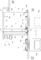
- FIG. 2 is a side view showing an outline of the inter-sub-route connection path 22 including the straddling portion M
- FIGS. 4 to 6 are enlarged views of the main part of FIG.
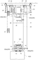
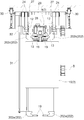
- FIGS. 7 to 9 are cross-sectional views of the main part of the inter-sub-path connection path 22.
- 7 is a cross-sectional view when viewed in the traveling direction X of the article transport vehicle 3 in FIG. 2
- FIG. 8 is when viewed from the side opposite to the traveling direction X of the article transport vehicle 3 in FIG. It is sectional drawing.
- the inter-sub-route connection route 22 as the second travel route is arranged with a height different from the main route 20 in the straddling part M.
- the traveling of the article transporting vehicle 3 and the traveling of the article transporting vehicle 3 on the inter-sub-route connection path 22 are configured to be allowed to each other.
- the main route 20 is shown as a travel route for traveling the article transport vehicle 3 along a direction perpendicular to the paper surface
- the inter-sub-route connection route 22 is an article in the direction of the arrow X. It is shown as a travel route on which the transport vehicle 3 travels.
- a first traveling rail 201 that forms the main route 20 and a second traveling rail 202 that forms the inter-sub-route connection route 22 are provided.
- the first traveling rails 201 are provided as a pair on the left and right sides with an interval in the lateral width direction of the article transport vehicle 3, and the second traveling rail 202 also has a lateral width of the article transport vehicle 3 as shown in FIGS. 7 and 8.
- a pair of left and right are provided at intervals in the direction.
- the pair of left and right straight portions of the first traveling rail 201 are separated from each other, but the portion between the pair of left and right straight portions is omitted in FIG. 2.
- the second traveling rail 202 that forms the inter-sub-route connection path 22 is upstream and downstream in the traveling direction X of the article transport vehicle 3 on the main path 20 (one in the width direction of the main path 20).
- the first height rail part 202a disposed at the same height in the vertical direction as the first traveling rail 201 on the side and the other side), and the straddle part M has a height above the first traveling rail 201 on the upper side.
- the main route 20 as the first travel route and the sub route 21 as the third travel route are arranged so as to have the same height in the vertical direction.
- the connecting route that connects the main route 20 and the sub route 21 is also arranged to be the same height in the vertical direction as the main route 20 and the sub route 21.
- the straddling part M in the inter-sub-route connection path 22 is set so as to continuously straddle both of the pair of straight portions of the main path 20.
- a second height rail portion 202c is disposed in the straddling portion M. That is, the second height rail portion 202c has one end in the traveling direction X and the other end, and the distance between the one end and the other end (that is, the second height).
- the length of the rail portion 202c) is larger than the distance between the pair of straight portions of the main path 20.
- the end on one side in a plan view is in a position beyond one of the pair of straight portions of the main path 20 in the traveling direction X, and the end on the other side is in the traveling direction X of the main path 20.
- part M is set as the adjacent site
- the set distance is set to a distance longer than the front-rear width of the article transporting vehicle 3, and the article transporting vehicle 3 is accommodated in the adjacent portion P.
- Each of the adjacent parts P on both sides is provided with a lift rail part 202c.
- a part farther away from the adjacent part P toward the sub route 21 is set as a separation part Q.
- a first height rail portion 202a is disposed in each of the separation portions Q on both sides.
- the second height rail portion 202b disposed in the straddling portion M is disposed at a higher position with respect to the first traveling rail 201, but the second height rail portion 202b is disposed at the first position.
- the traveling rail 201 is disposed at a height spaced above the traveling rail 201 by a distance longer than the vertical width of the article transport vehicle 3 traveling at the second height rail portion 202b. Accordingly, the article transport vehicle 3 traveling on the first travel rail 201 and the article transport vehicle 3 traveling on the second height rail portion 202b do not interfere with each other, and the article transport on the first travel rail 201 is performed.
- the traveling of the vehicle 3 and the traveling of the article transport vehicle 3 at the second height rail portion 202b are allowed to each other. As a result, traveling of the article transport vehicle 3 on the first travel rail 201 and traveling of the article transport vehicle 3 on the second height rail portion 202b can be performed independently.
- the lifting / lowering rail part 202c is located upstream and downstream in the traveling direction X of the article transport vehicle 3 in the straddling part M. And both.
- the upstream elevating rail part 202c and the downstream elevating rail part 202c in the traveling direction X of the article transporting vehicle 3 have the same configuration except that the installation position of the article transporting vehicle 3 in the traveling direction X is opposite. Therefore, only the upstream side in the traveling direction X of the article transport vehicle 3 will be described based on FIGS.
- the elevating device 23 that elevates the elevating rail portion 202c to the first height and the second height is capable of winding and unwinding the suspending belt 24 that supports the elevating rail portion 202c.
- the take-up / feeding device 25 and an electric motor 26 (corresponding to a drive unit) for causing the winding / feeding device 25 to take-up and feed-out are configured.
- Four suspension belts 24 are provided, each one end of which is connected to the take-up / feeding device 25, the middle part of which is wound around a plurality of rotation guide bodies 27, and the other end. Is connected to the lifting rail part 202c.
- the suspension belt 24 is not directly connected to the lift rail portion 202c, but via a coupling body 28 as shown in FIGS. Connected to the lifting rail part 202c.
- a pair of left and right lifting rail portions 202 c are provided at intervals in the lateral width direction of the article transport vehicle 3, and the pair of left and right lifting rail portions 202 c are connected by the connecting body 28.
- the connecting body 28 has a portion extending upward from each of the pair of left and right lifting rail portions 202c, and a straight portion connecting the upper ends of the extending portions, and is formed in a U shape as a whole. Yes.
- the suspension belt 24 is connected to the coupling body 28, and the suspension belt 24 is wound up and fed out, so that the pair of left and right lifting rail portions 202c remain spaced apart in the lateral width direction of the article transport vehicle 3. Can be moved up and down.
- the connection body 28 has connected the left-right paired raising / lowering rail part 202c, forming the space which the traveling drive part 9 of the article conveyance vehicle 3 can pass.
- the lifting device 23 causes the winding / feeding device 25 to be wound or fed by the driving force of the electric motor 26 to wind or feed the four suspension belts 24 to make a pair of left and right lifts.
- the rail part 202c is configured to move up and down to a first height (see FIG. 4) and a second height (see FIG. 6).
- the lifting / lowering rail part 202c is lifted / lowered by the lifting / lowering device 23.
- the lifting / lowering rail part 202c is moved up and down in order to prevent misalignment, shaking, etc.
- a bar-shaped lifting guide 31 extending in the direction is provided.
- a sliding body 32 that can be moved up and down integrally with the lifting rail portion 202 c is slidably provided on the lifting rail portion 202 c in a state of being externally fitted to the lifting guide 31.
- the elevating rail portion 202 c is guided by the elevating guide 31 and moved up and down as the sliding body 32 slides while being externally fitted to the elevating guide 31.
- the lifting device 23 is supported by an upper end side portion of a support body 29 formed in a frame shape.
- the support 29 is suspended and supported on the ceiling by the suspension support 30, and the first height rail portion 202 a is fixed to the lower end of the support 29.
- the support 29 is disposed above the first height rail portion 202a in the separation portion Q.
- the winding / feeding device 25 and the electric motor 26 in the lifting device 23 are connected within the lifting range in which the lifting rail portion 202c is lifted and lowered between the first height and the second height in the vertical direction and between the sub-paths.
- the lifting rail part 202 c is arranged on both the upstream side and the downstream side in the traveling direction X of the article transport vehicle 3 of the straddling part M.
- the upstream lifting / lowering rail part 202c is positioned at a first height continuous to the first height rail part 202a and the downstream lifting / lowering rail part 202c. Is positioned at a second height continuous with the second height rail portion 202b.
- the article transport vehicle 3 travels on the first height rail portion 202a disposed in the separation portion Q, and is disposed in the adjacent portion P from the first height rail portion 202a. Transfer to the lift rail portion 202c located at the first height and stop at the lift rail portion 202c. Then, as shown in FIG. 5, the lifting rail part 202 c to which the article transport vehicle 3 has been transferred is raised from the first height by the lifting device 23, and as shown in FIG. 6, the lift rail to which the article transport vehicle 3 has been transferred has been transferred. The part 202c is raised to a second height that is continuous with the second height rail part 202b disposed in the straddling part M.
- the article transporting vehicle 3 travels on the lifting rail part 202c and transfers from the lifting rail part 202c to the second height rail part 202b disposed in the straddling part M.
- the second height rail portion 202b is disposed at a higher position with respect to the first travel rail 201, the travel of the article transport vehicle 3 on the first travel rail 201 in the main route 20 is performed. Independently, the article transport vehicle 3 can travel on the second height rail portion 202b.
- the article transport vehicle 3 is disposed at the first height rail portion 202a and the adjacent portion P disposed at the separation portion Q on the upstream side of the straddling portion M in the traveling direction X of the article transport vehicle 3. If the second height rail portion 202b disposed in the straddling portion M is sequentially traveled after traveling on the lifting rail portion 202c, the article is similarly disposed on the downstream side of the straddling portion M in the traveling direction X of the article transport vehicle 3. The transport vehicle 3 sequentially travels on the lifting rail portion 202c disposed in the adjacent portion P and the first height rail portion 202a disposed in the separation portion Q.
- the article transport vehicle 3 has the lifting rail part 202c located at the second height arranged at the adjacent part P from the second height rail part 202b arranged at the straddling part M. And the lifting / lowering rail part 202c to which the article transport vehicle 3 has been transferred is lowered from the second position to the first position. Then, the article transport vehicle 3 travels from the lifting rail part 202c to the first height rail part 202a.
- the article transport vehicle 3 is mainly connected to the first height rail portion 202a and the lifting rail portion 202c on one side in the lateral width direction of the main path 20 via the second height rail portion 202b of the straddling portion M.
- the inter-sub-path connecting path 22 is configured to be able to travel continuously from the lifting rail part 202c and the first height rail part 202a on the other side of the path 20 in the lateral width direction.
- a pair of left and right traveling rails A pair of left and right power supply lines 19 are provided in a state supported by 202, and the pair of left and right power supply lines 19 are wired at appropriate positions capable of supplying driving power to the power receiving coil 19 of the article transport vehicle 3. .
- the article transport vehicle 3 receives the driving power from the pair of left and right power supply lines 19 in any of the first height rail portion 202a, the second height rail portion 202b, and the lifting rail portion 202c. And can run appropriately.
- the lifting / lowering rail part 202c is moved up and down to the first height and the second height, but it is located at the second height even if it is located at the first height using a cableveyor B or the like. Even so, the power for driving can be supplied to the article transport vehicle 3 by the power supply line 19 supported by the lift rail portion 202c.
- the lifting rail part 202 c when the article transport vehicle 3 moves to the next rail part, the lifting rail part 202 c is lifted and lowered by the lifting device 23, and the lifting rail part upstream in the traveling direction of the article transporting vehicle 3.
- the initial state is such that 202c is positioned at a first height that is continuous with the first height rail portion 202a and the lower lift rail portion 202c is positioned at a second height that is continuous with the second height rail portion 202b. ing.
- the article transport vehicle 3 When the lifting rail part 202c is not positioned at the first height, the article transport vehicle 3 is prevented from traveling from the first height rail part 202a to the lifting rail part 202c, or the lifting rail part 202c. As shown in FIGS. 4 to 6, in order to prevent the article transport vehicle 3 from jumping out of the lift rail portion 202c when the vehicle is moved up and down between the first height and the second height, as shown in FIGS. 3 are provided with stoppers 33a to 33d for restricting the movement of 3.
- a first stopper 33a that restricts the movement of the article transport vehicle 3 from the first height rail part 202a to the lifting rail part 202c side, and an article conveyance from the lifting rail part 202c to the first height rail part 202a side.
- a second stopper 33b for restricting the movement of the vehicle 3 a third stopper 33c for restricting the movement of the article transport vehicle 3 from the lifting rail portion 202c to the second height rail portion 202b, and a second height rail portion 202b.
- a fourth stopper 33d for restricting the movement of the article transport vehicle 3 from the rail to the lifting rail portion 202c side.
- the third stopper 33c conveys the article to a contact position (a dotted line in FIG. 9) that contacts the traveling wheel 12 of the article transport vehicle 3 and a retreat position (a solid line in FIG. 9) retracted from the traveling wheel 12 of the article transport vehicle 3. It is composed of a plate-like body that can swing around a horizontal axis along the traveling direction of the vehicle 3.
- the third stopper 33c is located at the contact position as shown by a two-dot chain line in FIG.
- the third stopper 33c is urged to return to the contact position side by an urging means 34 (for example, an elastic body such as a coil spring or a leaf spring), and the position of the third stopper 33c is changed from the contact position to the retracted position.
- an urging means 34 for example, an elastic body such as a coil spring or a leaf spring
- a position changing operation unit 35c is provided. The position of the third stopper 33c is changed from the contact position to the retracted position by pressing the third stopper 33c with the position change operation unit 35c.
- the position changing operation portion 35c in the third stopper 33c is provided so as to extend downward from the support 29 supporting the lifting device 23, and the position changing operation is performed when the lifting rail portion 202c is raised to the second height.
- the third stopper 33c is pressed by the operation unit 35c. 4 to 6 show only the position change operation units 35b and 35d for the second and fourth stoppers 33b and 33d, and the position change operation unit for the first stopper 33a. The illustration is omitted for.
- the first to fourth stoppers 33a to 33d will be described.
- the first and second stoppers 33a and 33b are located at the retracted positions.
- the article transport vehicle 3 is allowed to move from the first height rail portion 202a to the lifting rail portion 202c.
- the article transport vehicle 3 can be transferred from the first height rail portion 202a to the lifting rail portion 202c located at the first height.
- the third and fourth stoppers 33c and 33d are located at the contact positions, and the movement of the article transport vehicle 3 from the second height rail portion 202b to the lifting rail portion 202c is restricted.
- the article transport vehicle 3 is prevented from moving from the second height rail portion 202b to the lifting rail portion 202c.
- the third and fourth stoppers 33c, 33d are located at the retracted position, and the second height rail part is moved from the lifting rail part 202c. Movement to the article transport vehicle 3 to 202b is permitted. Thereby, the article transport vehicle 3 can be transferred from the lifting rail part 202c located at the second height to the second height rail part 202b.
- the first and second stoppers 33a and 33d are located at the contact positions, and the movement of the article transport vehicle 3 from the second height rail portion 202b to the lifting rail portion 202c is restricted, and the Thus, the article transport vehicle 3 is prevented from moving from the first height rail portion 202a to the lifting rail portion 202c.
- all of the first to fourth stoppers 33a to 33d are positioned at the contact position during the lifting / lowering between the first height and the second height of the lifting rail portion 202c.
- the article transport vehicle 3 is prevented from jumping out from the lifting rail portion 202c or the article transporting vehicle 3 is erroneously moved to the lifting rail portion 202c side.
- the article transport vehicle 3 can be moved up and down between the first height and the second height in order to run the article transport vehicle 3 between the first height rail portion 202a and the second height rail portion 202b.
- an elevating rail part 202c instead of the elevating rail part, an inclined rail part that obliquely connects between the first height rail part and the second height rail part is connected. It can also be implemented. In this case, the article transport vehicle travels from the first height rail part to the inclined rail part upstream of the straddling part in the traveling direction of the article transporter, and the inclined rail part gradually moves from the lower side to the upper side.
- the vehicle travels diagonally so as to rise, and travels from the inclined rail part to the second height rail part. Further, on the downstream side in the travel direction of the article transport vehicle from the straddling part, the vehicle travels diagonally so that the second height rail part travels to the inclined rail part, and the inclined rail part gradually descends from the upper side to the lower side. The vehicle travels from the inclined rail part to the first height rail part.
- the inter-sub-route connection route 22 that is the second travel route is disposed at a higher position than the main route 20 that is the first travel route.
- the inter-sub-route connection path 22 that is the second travel path may be disposed at a lower position than the main path 20 that is the first travel path. That is, when there is a space above the first travel rail that forms the first travel route, it is effective to arrange the second travel route at a higher position than the first travel route, When there is a space below the first travel rail that forms the first travel route, it is effective to dispose the second travel route at a lower position than the first travel route.
- the sub route 21 as the third travel route is provided on one side and the other side of the main route 20 as the first travel route
- the sub route 21 on the one side of the main route 20 is provided.
- the inter-sub-route connection path 22 that connects the path 21 and the other side sub-path 21 is used as the second travel path
- the first travel path is changed from one side to the other side with respect to the first travel path.
- the equipment for transporting goods according to the present invention can be applied as long as the equipment has the second travel route straddling the road.
- the article conveying facility according to the present invention can be used in, for example, a semiconductor manufacturing factory or a processing facility.
- traveling rail 3 article transport vehicle 20 first traveling path 21 third traveling path 22 second traveling path 23 lifting device 26 drive unit 201 first traveling rail 202 second traveling rail 202a first height rail part 202b second height Rail part 202c Elevating rail part M Crossing part
Landscapes
- Engineering & Computer Science (AREA)
- Mechanical Engineering (AREA)
- Transportation (AREA)
- Warehouses Or Storage Devices (AREA)
- Intermediate Stations On Conveyors (AREA)
- Container, Conveyance, Adherence, Positioning, Of Wafer (AREA)
- Platform Screen Doors And Railroad Systems (AREA)
- Control Of Position, Course, Altitude, Or Attitude Of Moving Bodies (AREA)
Abstract
Description
第1走行経路と、前記第1走行経路の横幅方向の一方側から他方側に前記第1走行経路を跨ぐ第2走行経路とを有する前記走行経路と、
前記走行経路に沿って走行自在な物品搬送車とを備え、
前記第2走行経路において前記第1走行経路を跨ぐ跨ぎ部位では、前記第2走行経路が前記第1走行経路に対して上下方向で異なる高さに配設されて、前記第1走行経路での前記物品搬送車の走行と前記第2走行経路での前記物品搬送車の走行とが互いに許容自在に構成され、前記物品搬送車は、前記第1走行経路の横幅方向の一方側から前記跨ぎ部位を経由して前記第1走行経路の横幅方向の他方側に連続して前記第2走行経路を走行自在に構成されている。
そして、物品搬送車は、第1走行経路の横幅方向の一方側から跨ぎ部位を経由して第1走行経路の横幅方向の他方側に連続して第2走行経路を走行自在に構成されているので、物品搬送車が第2走行経路を走行することで、第1走行経路を跨いで走行することができる。上記特許文献1に記載の如く主経路及び副経路が備えられた設備では、例えば、主経路を第1走行経路とし、その主経路の一方側の副経路と他方側の副経路とを連結する走行経路として、主経路を跨ぐ第2走行経路を備えることができる。このようにして、第1走行経路と第2走行経路とを備えた設備では、物品搬送車が第2走行経路を走行することにより、第1走行経路としての主経路を走行することなく、一方側の副経路と他方側の副経路との間で走行することができる。したがって、上記特許文献1に記載の設備の如く、搬送コンベヤを設けなくても、第1走行経路を跨ぐ第2走行経路を備えることで、物品搬送車の走行距離を短くしながら、主経路の一方側の副経路から他方側の副経路まで物品搬送車により物品を搬送することができる。しかも、主経路の一方側の副経路から他方側の副経路まで物品搬送車の走行により物品を搬送することができるので、このときの搬送速度を、物品搬送車の走行速度等の比較的速い速度とすることができ、例えば、搬送コンベヤによる搬送速度よりも速い搬送速度にて物品を搬送することができる。
以上のことから、構成の簡素化及びコストの低減を図りながら、物品搬送車の走行距離を短くできるとともに、搬送速度も比較的速い速度とすることができ、搬送能力の低下を防止することができる物品搬送設備を実現することができる。
前記ストッパーは、前記物品搬送車の通過を規制する当接位置と前記物品搬送車の通過を許す退避位置の間で変位可能であり、前記ストッパーは、前記前記昇降レール部位の前記第2高さへの到達に伴い、天井側に支持された位置変更操作部と接当することにより前記当接位置から退避位置へ変位されるよう構成されていることが好ましい。
この物品搬送設備は、図1に示すように、複数の物品処理部1を経由する状態で走行レール2が天井側に設置されて走行経路Sが形成されており、走行経路Sに沿って一方向に移動自在な天井搬送式の物品搬送車3が複数設けられている。この物品搬送設備では、図2に示すように、半導体基板を収納した容器を物品4として、物品搬送車3が複数の物品処理部1の間で物品4を搬送するように構成されている。走行レール2は、吊り下げ支持具30により天井部に固定状態で設置されている。
物品搬送車3は、把持部6を上昇位置に位置させた状態で走行レール2に沿って移動し、複数のステーション8のうち、移載対象のステーション8に対応する停止位置に停止した状態で上昇位置と下降位置との間で把持部6を昇降させることにより、ステーション8との間で物品4の授受(すなわち、移載)を行うように構成されている。
図3に示すように、走行レール2は、物品搬送車3の横幅方向に間隔を隔てて左右一対設けられており、走行駆動部9には、駆動モータ11にて回転駆動されて左右一対の走行レール2夫々の水平面に沿う上面を転動する走行輪12と、左右一対の走行レール2夫々の対向する上下方向に沿う側面に接当する回転自在な走行案内輪13とが設けられている。そして、走行輪12が駆動モータ11にて物品搬送車3の横幅方向に沿う軸心周りで回転駆動し、上下軸心周りで回転自在な走行案内輪13が左右一対の走行レール2にて当接案内されることにより、物品搬送車3が走行レール2に案内されて走行するように構成されている。
上述の如く、副経路間連結経路22は、主経路20の直線部分を跨ぐ部位が跨ぎ部位Mとなっている。本発明に係る物品搬送設備では、上述の如く、この跨ぎ部位Mにおいて、主経路20にて物品搬送車3が走行する位置と副経路間連結経路22にて物品搬送車3が走行する位置とを上下方向に異ならせることで、主経路20での物品搬送車3の走行と副経路間連結経路22での物品搬送車3の走行とを互いに干渉することなく行えるようにしている。
ここで、図2は、跨ぎ部位Mを含む副経路間連結経路22の概略を示す側面図であり、図4~図6は、図2の要部を拡大して物品搬送車3の走行過程を示す図であり、図7~図9は、副経路間連結経路22の要部の断面図である。図7は、図2における物品搬送車3の走行方向Xにて見たときの断面図であり、図8は、図2における物品搬送車3の走行方向Xとは反対側から見たときの断面図である。
図2を再度参照すると、副経路間連結経路22を形成する第2走行レール202は、主経路20の物品搬送車3の走行方向Xの上流側及び下流側(主経路20の横幅方向の一方側及び他方側)において第1走行レール201と上下方向で同じ高さに配設された第1高さレール部位202aと、跨ぎ部位Mにおいて第1走行レール201に対して上方側に高さを異ならせる状態で(すなわち、第1走行レール201よりも高い位置に)配設された第2高さレール部位202bと、主経路20の物品搬送車3の走行方向Xの上流側及び下流側と跨ぎ部位Mとの間において第1高さレール部位202aに連続する第1高さ(図4参照)と第2高さレール部位202bに連続する第2高さ(図5参照)とに昇降装置23により昇降自在な昇降レール部位202cとを備えている。
図2に示すように、副経路間連結経路22には、跨ぎ部位Mの物品搬送車3の走行方向Xの上流側と下流側との双方に昇降レール部位202cが配設されているが、物品搬送車3が跨ぎ部位Mを走行するときには、初期状態として、上流側の昇降レール部位202cが第1高さレール部位202aに連続する第1高さに位置され且つ下流側の昇降レール部位202cが第2高さレール部位202bに連続する第2高さに位置されている。これにより、図4に示すように、物品搬送車3は、離間部位Qに配設された第1高さレール部位202aを走行し、その第1高さレール部位202aから隣接部位Pに配設された第1高さに位置する昇降レール部位202cに乗り移り、昇降レール部位202cにて停止される。そして、図5に示すように、昇降装置23により物品搬送車3が乗り移った昇降レール部位202cが第1高さから上昇され、図6に示すように、その物品搬送車3が乗り移った昇降レール部位202cが跨ぎ部位Mに配設された第2高さレール部位202bに連続する第2高さまで上昇される。その後、物品搬送車3は、昇降レール部位202cを走行し、その昇降レール部位202cから跨ぎ部位Mに配設された第2高さレール部位202bに乗り移る。そして、上述の如く、第2高さレール部位202bが第1走行レール201に対して高い位置に配設されていることから、主経路20における第1走行レール201での物品搬送車3の走行とは独立して、物品搬送車3が第2高さレール部位202bを走行することができる。
第3ストッパー33cは、物品搬送車3の走行輪12に当接する当接位置(図9中点線)と物品搬送車3の走行輪12から退避した退避位置(図9中実線)とに物品搬送車3の進行方向に沿った水平軸心周りで揺動自在な板状体にて構成されている。そして、第3ストッパー33cは、図9において2点鎖線で示すように、当接位置に位置することで、走行輪12に当接して物品搬送車3の移動を規制し、図9において実線で示すように、退避位置に位置することで、走行輪12に当接せずに物品搬送車3の移動を許容している。また、第3ストッパー33cは、付勢手段34(例えばコイルバネや板バネ等の弾性体)により当接位置側に復帰付勢されており、第3ストッパー33cを当接位置から退避位置に位置変更させるために、位置変更操作部35cが備えられている。位置変更操作部35cにて第3ストッパー33cを押圧操作することで、第3ストッパー33cを当接位置から退避位置に位置変更させている。第3ストッパー33cにおける位置変更操作部35cは、昇降装置23を支持する支持体29から下方側に延びるように備えられており、昇降レール部位202cが第2高さに上昇されると、位置変更操作部35cにて第3ストッパー33cを押圧操作するようになっている。ちなみに、図4~6では、位置変更操作部については、第2、第4ストッパー33b、33dについての位置変更操作部35b、35dのみを図示しており、第1ストッパー33aについての位置変更操作部については図示を省略している。
また、図5に示すように、昇降レール部位202cの第1高さと第2高さとの間での昇降中には、第1~第4ストッパー33a~33dの全てが当接位置に位置しており、昇降レール部位202cから物品搬送車3が飛び出すことや、誤って昇降レール部位202c側へ物品搬送車3が移動されるのを阻止している。
(1)上記実施形態では、第1高さレール部位202aと第2高さレール部位202bとの間で物品搬送車3を走行させるために、第1高さと第2高さとの間で昇降自在な昇降レール部位202cを備えた例を示したが、例えば、昇降レール部位に代えて、第1高さレール部位と第2高さレール部位との間を斜めに傾斜して繋ぐ傾斜レール部位を備えて実施することもできる。この場合には、跨ぎ部位よりも物品搬送車の走行方向の上流側では、物品搬送車が、第1高さレール部位から傾斜レール部位に走行し、傾斜レール部位を下方側から上方側に徐々に上昇するように斜めに走行し、傾斜レール部位から第2高さレール部位に走行する。また、跨ぎ部位よりも物品搬送車の走行方向の下流側では、第2高さレール部位から傾斜レール部位に走行し、傾斜レール部位を上方側から下方側に徐々に下降するように斜めに走行し、傾斜レール部位から第1高さレール部位に走行する。
3 物品搬送車
20 第1走行経路
21 第3走行経路
22 第2走行経路
23 昇降装置
26 駆動部
201 第1走行レール
202 第2走行レール
202a 第1高さレール部位
202b 第2高さレール部位
202c 昇降レール部位
M 跨ぎ部位
Claims (5)
- 物品搬送設備であって、これは、
第1走行経路と、前記第1走行経路の横幅方向の一方側から他方側に前記第1走行経路を跨ぐ第2走行経路とを有する前記走行経路と、
前記走行経路に沿って走行自在な物品搬送車とを備え、
前記第2走行経路における前記第1走行経路を跨ぐ跨ぎ部位では、前記第2走行経路が前記第1走行経路に対して上下方向で異なる高さに配設されて、前記第1走行経路での前記物品搬送車の走行と前記第2走行経路での前記物品搬送車の走行とが互いに許容されるよう構成され、前記物品搬送車は、前記第1走行経路の横幅方向の一方側から前記跨ぎ部位を経由して前記第1走行経路の横幅方向の他方側に連続して前記第2走行経路を走行自在に構成されている物品搬送設備。 - 前記走行経路として、前記第1走行経路より分岐し、且つ、前記第1走行経路に合流する第3走行経路が備えられ、前記第3走行経路は、前記第1走行経路の横幅方向において前記第1走行経路の一方側と他方側との両側に配設され、前記第2走行経路は、その一端部が前記第1走行経路の横幅方向で一方側に配設された前記第3走行経路に接続され、その他端部が前記第1走行経路の横幅方向で他方側に配設された前記第3走行経路に接続されて、前記第1走行経路の横幅方向で一方側に配設された前記第3走行経路と他方側に配設された前記第3走行経路との間で前記物品搬送車を走行自在に構成されている請求項1に記載の物品搬送設備。
- 前記第1走行経路を形成する第1走行レールと、前記第2走行経路を形成する第2走行レールとが設けられ、前記第2走行レールは、前記第1走行経路の横幅方向の一方側及び他方側において前記第1走行レールと上下方向で同じ高さに配設された第1高さレール部位と、前記跨ぎ部位において前記第1走行レールと上下方向で異なる高さに配設された第2高さレール部位と、前記第1走行経路の横幅方向の一方側及び他方側と前記跨ぎ部位との間において前記第1高さレール部位に連続する第1高さと前記第2高さレール部位に連続する第2高さとに昇降装置により昇降自在な昇降レール部位とを備えている請求項1に記載の物品搬送設備。
- 前記第1走行レール及び前記第2走行レールは、左右一対備えられ、前記昇降装置は、駆動部の駆動力により前記昇降レール部位を第1高さと第2高さとに昇降自在に構成され、前記駆動部は、前記第1走行経路の横幅方向で前記昇降レール部位よりも前記第1高さレール部位が配設される側において、上下方向で前記昇降レール部位が第1高さと第2高さとの間で昇降される昇降範囲内に収まり且つ前記第2走行経路の横幅方向で左右一対の前記第2走行レールの間の空間に収まる状態で配設されている請求項3に記載の物品搬送設備。
- 少なくとも前記昇降レール部位には、前記物品搬送車の移動を規制するストッパーが設けられており、
前記ストッパーは、前記物品搬送車の通過を規制する当接位置と前記物品搬送車の通過を許す退避位置の間で変位可能であり、
前記ストッパーは、前記前記昇降レール部位の前記第2高さへの到達に伴い、天井側に支持された位置変更操作部と接当することにより前記当接位置から退避位置へ変位されるよう構成されている請求項3に記載の物品搬送設備。
Priority Applications (4)
| Application Number | Priority Date | Filing Date | Title |
|---|---|---|---|
| SG2013008073A SG187685A1 (en) | 2010-08-04 | 2011-06-17 | Goods transport facility |
| KR1020137003237A KR101836963B1 (ko) | 2010-08-04 | 2011-06-17 | 물품 반송 설비 |
| CN201180038266.XA CN103025629B (zh) | 2010-08-04 | 2011-06-17 | 物品运送设备 |
| US13/813,788 US9199826B2 (en) | 2010-08-04 | 2011-06-17 | Article transport facility |
Applications Claiming Priority (2)
| Application Number | Priority Date | Filing Date | Title |
|---|---|---|---|
| JP2010175563A JP5477651B2 (ja) | 2010-08-04 | 2010-08-04 | 物品搬送設備 |
| JP2010-175563 | 2010-08-04 |
Publications (1)
| Publication Number | Publication Date |
|---|---|
| WO2012017743A1 true WO2012017743A1 (ja) | 2012-02-09 |
Family
ID=45559256
Family Applications (1)
| Application Number | Title | Priority Date | Filing Date |
|---|---|---|---|
| PCT/JP2011/063892 Ceased WO2012017743A1 (ja) | 2010-08-04 | 2011-06-17 | 物品搬送設備 |
Country Status (8)
| Country | Link |
|---|---|
| US (1) | US9199826B2 (ja) |
| JP (1) | JP5477651B2 (ja) |
| KR (1) | KR101836963B1 (ja) |
| CN (1) | CN103025629B (ja) |
| MY (1) | MY165013A (ja) |
| SG (1) | SG187685A1 (ja) |
| TW (1) | TWI496728B (ja) |
| WO (1) | WO2012017743A1 (ja) |
Cited By (1)
| Publication number | Priority date | Publication date | Assignee | Title |
|---|---|---|---|---|
| WO2014032300A1 (zh) * | 2012-08-31 | 2014-03-06 | 深圳市华星光电技术有限公司 | 一种玻璃基板的仓储系统以及玻璃基板仓储方法 |
Families Citing this family (24)
| Publication number | Priority date | Publication date | Assignee | Title |
|---|---|---|---|---|
| US9689266B2 (en) * | 2011-07-28 | 2017-06-27 | Vestas Wind Systems A/S | Production facility comprising a transport system for processing elongated products, in particular wind turbine blades, with elongated mould assemblies |
| JP5880991B2 (ja) * | 2012-06-08 | 2016-03-09 | 村田機械株式会社 | 搬送システム及び搬送システムでの物品の一時保管方法 |
| KR101418812B1 (ko) * | 2012-10-31 | 2014-07-16 | 크린팩토메이션 주식회사 | 웨이퍼 퍼지 가능한 천장 보관 장치 |
| WO2015071951A1 (ja) * | 2013-11-12 | 2015-05-21 | 株式会社ダイフク | 物品収納設備(article storage facility) |
| US20160171436A1 (en) | 2014-11-21 | 2016-06-16 | Deliveright Logistics, Inc. | Delivery management systems and methods for zero-inventory distribution |
| CN107813846B (zh) * | 2016-08-23 | 2019-04-12 | 陈锡龙 | 轨道系统 |
| JP6620707B2 (ja) * | 2016-09-09 | 2019-12-18 | 株式会社ダイフク | 物品搬送設備 |
| CN106241323A (zh) * | 2016-09-30 | 2016-12-21 | 郑州云海信息技术有限公司 | 一种移载设备、系统及方法 |
| JP6589820B2 (ja) * | 2016-10-31 | 2019-10-16 | 株式会社ダイフク | 通行規制装置 |
| JP6652084B2 (ja) * | 2017-02-09 | 2020-02-19 | 株式会社ダイフク | 物品搬送設備 |
| US11515186B2 (en) * | 2017-11-02 | 2022-11-29 | Murata Machinery, Ltd. | Ceiling conveyance vehicle system and temporary storage method for articles in ceiling conveyance vehicle system |
| KR101882507B1 (ko) * | 2017-12-28 | 2018-07-31 | 주식회사 알티자동화 | 클린 리프터 |
| JP7131107B2 (ja) * | 2018-06-11 | 2022-09-06 | 村田機械株式会社 | 搬送車の走行設備 |
| CN109473384A (zh) * | 2018-12-15 | 2019-03-15 | 深圳市华星光电半导体显示技术有限公司 | 传送装置及刻蚀设备 |
| KR102226761B1 (ko) * | 2019-10-11 | 2021-03-11 | 세메스 주식회사 | 대상물 이송 장치 |
| JP7238736B2 (ja) * | 2019-11-13 | 2023-03-14 | 株式会社ダイフク | 物品昇降装置 |
| KR102811212B1 (ko) * | 2020-04-29 | 2025-05-21 | 세메스 주식회사 | 물품 이송 장치 |
| US12131932B2 (en) | 2020-07-28 | 2024-10-29 | Changxin Memory Technologies, Inc. | Transfer system and transfer method |
| CN113998403B (zh) * | 2020-07-28 | 2022-09-23 | 长鑫存储技术有限公司 | 转运系统及转运方法 |
| CN112279092A (zh) * | 2020-10-10 | 2021-01-29 | 中建筑港集团有限公司 | 一种盾构施工用辅助运刀装置 |
| KR20240050613A (ko) * | 2022-10-12 | 2024-04-19 | 삼성전자주식회사 | 반도체 장치의 제조용 장치 및 이를 이용한 반도체 장치의 제조 방법 |
| KR102903674B1 (ko) * | 2022-10-31 | 2025-12-23 | 주식회사 포스코디엑스 | 크로스오버를 활용한 자동분류 시스템 및 방법 |
| JP2024162876A (ja) * | 2023-05-11 | 2024-11-21 | 株式会社ダイフク | 物品搬送設備 |
| JP2024166682A (ja) * | 2023-05-19 | 2024-11-29 | 株式会社ダイフク | 物品搬送設備 |
Citations (4)
| Publication number | Priority date | Publication date | Assignee | Title |
|---|---|---|---|---|
| JPH04366201A (ja) * | 1991-06-12 | 1992-12-18 | Fujitsu Ltd | 搬送装置 |
| JPH0510331U (ja) * | 1991-01-16 | 1993-02-09 | 村田機械株式会社 | 物品搬送装置 |
| JPH08157049A (ja) * | 1994-12-05 | 1996-06-18 | Nakanishi Kinzoku Kogyo Kk | 搬送装置 |
| JP2006313463A (ja) * | 2005-05-09 | 2006-11-16 | Murata Mach Ltd | 搬送台車システム |
Family Cites Families (10)
| Publication number | Priority date | Publication date | Assignee | Title |
|---|---|---|---|---|
| USRE28306E (en) * | 1970-09-10 | 1975-01-21 | Automatic electric power supply and speed control system for automated driverless vehicles | |
| US4841871A (en) * | 1984-04-19 | 1989-06-27 | Leibowitz Martin Nick | Modular transportation system with aerodynamic lift augmented traction vehicles |
| DE3606070A1 (de) * | 1985-04-16 | 1986-10-23 | Mannesmann AG, 4000 Düsseldorf | Hub- und senkstation fuer ein schienenfahrzeug |
| ATE521514T1 (de) * | 2001-03-01 | 2011-09-15 | Cascade Eng Inc | Transportsystem für einzelpersonen oder gruppen |
| TWI233913B (en) * | 2002-06-06 | 2005-06-11 | Murata Machinery Ltd | Automated guided vehicle system |
| JP2005031873A (ja) * | 2003-07-10 | 2005-02-03 | Trecenti Technologies Inc | 搬送システムおよび半導体製造システム |
| JP2005243729A (ja) * | 2004-02-24 | 2005-09-08 | Asyst Shinko Inc | 搬送システム |
| JP4858673B2 (ja) * | 2005-05-13 | 2012-01-18 | ムラテックオートメーション株式会社 | 懸垂式昇降搬送台車の搬送システム |
| JP4807579B2 (ja) * | 2006-09-13 | 2011-11-02 | 株式会社ダイフク | 基板収納設備及び基板処理設備 |
| JP4366663B2 (ja) * | 2007-06-28 | 2009-11-18 | 村田機械株式会社 | 搬送台車システム |
-
2010
- 2010-08-04 JP JP2010175563A patent/JP5477651B2/ja active Active
-
2011
- 2011-06-17 WO PCT/JP2011/063892 patent/WO2012017743A1/ja not_active Ceased
- 2011-06-17 MY MYPI2013000322A patent/MY165013A/en unknown
- 2011-06-17 CN CN201180038266.XA patent/CN103025629B/zh active Active
- 2011-06-17 KR KR1020137003237A patent/KR101836963B1/ko active Active
- 2011-06-17 US US13/813,788 patent/US9199826B2/en active Active
- 2011-06-17 SG SG2013008073A patent/SG187685A1/en unknown
- 2011-06-24 TW TW100122218A patent/TWI496728B/zh active
Patent Citations (4)
| Publication number | Priority date | Publication date | Assignee | Title |
|---|---|---|---|---|
| JPH0510331U (ja) * | 1991-01-16 | 1993-02-09 | 村田機械株式会社 | 物品搬送装置 |
| JPH04366201A (ja) * | 1991-06-12 | 1992-12-18 | Fujitsu Ltd | 搬送装置 |
| JPH08157049A (ja) * | 1994-12-05 | 1996-06-18 | Nakanishi Kinzoku Kogyo Kk | 搬送装置 |
| JP2006313463A (ja) * | 2005-05-09 | 2006-11-16 | Murata Mach Ltd | 搬送台車システム |
Cited By (1)
| Publication number | Priority date | Publication date | Assignee | Title |
|---|---|---|---|---|
| WO2014032300A1 (zh) * | 2012-08-31 | 2014-03-06 | 深圳市华星光电技术有限公司 | 一种玻璃基板的仓储系统以及玻璃基板仓储方法 |
Also Published As
| Publication number | Publication date |
|---|---|
| TWI496728B (zh) | 2015-08-21 |
| CN103025629B (zh) | 2014-12-31 |
| KR101836963B1 (ko) | 2018-03-09 |
| SG187685A1 (en) | 2013-03-28 |
| KR20130139227A (ko) | 2013-12-20 |
| TW201210922A (en) | 2012-03-16 |
| US20130195588A1 (en) | 2013-08-01 |
| MY165013A (en) | 2018-02-28 |
| CN103025629A (zh) | 2013-04-03 |
| JP2012035939A (ja) | 2012-02-23 |
| US9199826B2 (en) | 2015-12-01 |
| JP5477651B2 (ja) | 2014-04-23 |
Similar Documents
| Publication | Publication Date | Title |
|---|---|---|
| JP5477651B2 (ja) | 物品搬送設備 | |
| JP5472209B2 (ja) | 物品搬送設備 | |
| JP5440870B2 (ja) | 物品搬送設備 | |
| JP5686501B2 (ja) | 物品搬送設備 | |
| JP5527619B2 (ja) | 天井設置型の物品搬送設備 | |
| US8448579B2 (en) | Article transport facility | |
| JP5590422B2 (ja) | 物品搬送設備 | |
| JP5674041B2 (ja) | 物品搬送設備 | |
| JP5099454B2 (ja) | 交差部切換設備 | |
| CN102673964B (zh) | 物品运送设备 | |
| JP5344366B2 (ja) | 搬送システム | |
| KR101419358B1 (ko) | 반송시스템 | |
| JP5617868B2 (ja) | 搬送装置 |
Legal Events
| Date | Code | Title | Description |
|---|---|---|---|
| WWE | Wipo information: entry into national phase |
Ref document number: 201180038266.X Country of ref document: CN |
|
| 121 | Ep: the epo has been informed by wipo that ep was designated in this application |
Ref document number: 11814373 Country of ref document: EP Kind code of ref document: A1 |
|
| NENP | Non-entry into the national phase |
Ref country code: DE |
|
| ENP | Entry into the national phase |
Ref document number: 20137003237 Country of ref document: KR Kind code of ref document: A |
|
| WWE | Wipo information: entry into national phase |
Ref document number: 13813788 Country of ref document: US |
|
| 122 | Ep: pct application non-entry in european phase |
Ref document number: 11814373 Country of ref document: EP Kind code of ref document: A1 |