WO2012005206A1 - ボール型等速ジョイント - Google Patents
ボール型等速ジョイント Download PDFInfo
- Publication number
- WO2012005206A1 WO2012005206A1 PCT/JP2011/065262 JP2011065262W WO2012005206A1 WO 2012005206 A1 WO2012005206 A1 WO 2012005206A1 JP 2011065262 W JP2011065262 W JP 2011065262W WO 2012005206 A1 WO2012005206 A1 WO 2012005206A1
- Authority
- WO
- WIPO (PCT)
- Prior art keywords
- inner ring
- ball
- groove
- constant velocity
- notch
- Prior art date
- Legal status (The legal status is an assumption and is not a legal conclusion. Google has not performed a legal analysis and makes no representation as to the accuracy of the status listed.)
- Ceased
Links
Images

Classifications
-
- F—MECHANICAL ENGINEERING; LIGHTING; HEATING; WEAPONS; BLASTING
- F16—ENGINEERING ELEMENTS AND UNITS; GENERAL MEASURES FOR PRODUCING AND MAINTAINING EFFECTIVE FUNCTIONING OF MACHINES OR INSTALLATIONS; THERMAL INSULATION IN GENERAL
- F16D—COUPLINGS FOR TRANSMITTING ROTATION; CLUTCHES; BRAKES
- F16D3/00—Yielding couplings, i.e. with means permitting movement between the connected parts during the drive
- F16D3/16—Universal joints in which flexibility is produced by means of pivots or sliding or rolling connecting parts
- F16D3/20—Universal joints in which flexibility is produced by means of pivots or sliding or rolling connecting parts one coupling part entering a sleeve of the other coupling part and connected thereto by sliding or rolling members
- F16D3/22—Universal joints in which flexibility is produced by means of pivots or sliding or rolling connecting parts one coupling part entering a sleeve of the other coupling part and connected thereto by sliding or rolling members the rolling members being balls, rollers, or the like, guided in grooves or sockets in both coupling parts
- F16D3/223—Universal joints in which flexibility is produced by means of pivots or sliding or rolling connecting parts one coupling part entering a sleeve of the other coupling part and connected thereto by sliding or rolling members the rolling members being balls, rollers, or the like, guided in grooves or sockets in both coupling parts the rolling members being guided in grooves in both coupling parts
-
- F—MECHANICAL ENGINEERING; LIGHTING; HEATING; WEAPONS; BLASTING
- F16—ENGINEERING ELEMENTS AND UNITS; GENERAL MEASURES FOR PRODUCING AND MAINTAINING EFFECTIVE FUNCTIONING OF MACHINES OR INSTALLATIONS; THERMAL INSULATION IN GENERAL
- F16D—COUPLINGS FOR TRANSMITTING ROTATION; CLUTCHES; BRAKES
- F16D3/00—Yielding couplings, i.e. with means permitting movement between the connected parts during the drive
- F16D3/16—Universal joints in which flexibility is produced by means of pivots or sliding or rolling connecting parts
- F16D3/24—Universal joints in which flexibility is produced by means of pivots or sliding or rolling connecting parts comprising balls, rollers, or the like between overlapping driving faces, e.g. cogs, on both coupling parts
-
- F—MECHANICAL ENGINEERING; LIGHTING; HEATING; WEAPONS; BLASTING
- F16—ENGINEERING ELEMENTS AND UNITS; GENERAL MEASURES FOR PRODUCING AND MAINTAINING EFFECTIVE FUNCTIONING OF MACHINES OR INSTALLATIONS; THERMAL INSULATION IN GENERAL
- F16D—COUPLINGS FOR TRANSMITTING ROTATION; CLUTCHES; BRAKES
- F16D3/00—Yielding couplings, i.e. with means permitting movement between the connected parts during the drive
- F16D3/16—Universal joints in which flexibility is produced by means of pivots or sliding or rolling connecting parts
- F16D3/20—Universal joints in which flexibility is produced by means of pivots or sliding or rolling connecting parts one coupling part entering a sleeve of the other coupling part and connected thereto by sliding or rolling members
- F16D3/22—Universal joints in which flexibility is produced by means of pivots or sliding or rolling connecting parts one coupling part entering a sleeve of the other coupling part and connected thereto by sliding or rolling members the rolling members being balls, rollers, or the like, guided in grooves or sockets in both coupling parts
- F16D3/223—Universal joints in which flexibility is produced by means of pivots or sliding or rolling connecting parts one coupling part entering a sleeve of the other coupling part and connected thereto by sliding or rolling members the rolling members being balls, rollers, or the like, guided in grooves or sockets in both coupling parts the rolling members being guided in grooves in both coupling parts
- F16D3/2237—Universal joints in which flexibility is produced by means of pivots or sliding or rolling connecting parts one coupling part entering a sleeve of the other coupling part and connected thereto by sliding or rolling members the rolling members being balls, rollers, or the like, guided in grooves or sockets in both coupling parts the rolling members being guided in grooves in both coupling parts where the grooves are composed of radii and adjoining straight lines, i.e. undercut free [UF] type joints
-
- F—MECHANICAL ENGINEERING; LIGHTING; HEATING; WEAPONS; BLASTING
- F16—ENGINEERING ELEMENTS AND UNITS; GENERAL MEASURES FOR PRODUCING AND MAINTAINING EFFECTIVE FUNCTIONING OF MACHINES OR INSTALLATIONS; THERMAL INSULATION IN GENERAL
- F16D—COUPLINGS FOR TRANSMITTING ROTATION; CLUTCHES; BRAKES
- F16D3/00—Yielding couplings, i.e. with means permitting movement between the connected parts during the drive
- F16D3/16—Universal joints in which flexibility is produced by means of pivots or sliding or rolling connecting parts
- F16D3/20—Universal joints in which flexibility is produced by means of pivots or sliding or rolling connecting parts one coupling part entering a sleeve of the other coupling part and connected thereto by sliding or rolling members
- F16D3/22—Universal joints in which flexibility is produced by means of pivots or sliding or rolling connecting parts one coupling part entering a sleeve of the other coupling part and connected thereto by sliding or rolling members the rolling members being balls, rollers, or the like, guided in grooves or sockets in both coupling parts
- F16D3/223—Universal joints in which flexibility is produced by means of pivots or sliding or rolling connecting parts one coupling part entering a sleeve of the other coupling part and connected thereto by sliding or rolling members the rolling members being balls, rollers, or the like, guided in grooves or sockets in both coupling parts the rolling members being guided in grooves in both coupling parts
- F16D2003/22303—Details of ball cages
-
- F—MECHANICAL ENGINEERING; LIGHTING; HEATING; WEAPONS; BLASTING
- F16—ENGINEERING ELEMENTS AND UNITS; GENERAL MEASURES FOR PRODUCING AND MAINTAINING EFFECTIVE FUNCTIONING OF MACHINES OR INSTALLATIONS; THERMAL INSULATION IN GENERAL
- F16D—COUPLINGS FOR TRANSMITTING ROTATION; CLUTCHES; BRAKES
- F16D3/00—Yielding couplings, i.e. with means permitting movement between the connected parts during the drive
- F16D3/16—Universal joints in which flexibility is produced by means of pivots or sliding or rolling connecting parts
- F16D3/20—Universal joints in which flexibility is produced by means of pivots or sliding or rolling connecting parts one coupling part entering a sleeve of the other coupling part and connected thereto by sliding or rolling members
- F16D3/22—Universal joints in which flexibility is produced by means of pivots or sliding or rolling connecting parts one coupling part entering a sleeve of the other coupling part and connected thereto by sliding or rolling members the rolling members being balls, rollers, or the like, guided in grooves or sockets in both coupling parts
- F16D3/223—Universal joints in which flexibility is produced by means of pivots or sliding or rolling connecting parts one coupling part entering a sleeve of the other coupling part and connected thereto by sliding or rolling members the rolling members being balls, rollers, or the like, guided in grooves or sockets in both coupling parts the rolling members being guided in grooves in both coupling parts
- F16D2003/22313—Details of the inner part of the core or means for attachment of the core on the shaft
-
- F—MECHANICAL ENGINEERING; LIGHTING; HEATING; WEAPONS; BLASTING
- F16—ENGINEERING ELEMENTS AND UNITS; GENERAL MEASURES FOR PRODUCING AND MAINTAINING EFFECTIVE FUNCTIONING OF MACHINES OR INSTALLATIONS; THERMAL INSULATION IN GENERAL
- F16D—COUPLINGS FOR TRANSMITTING ROTATION; CLUTCHES; BRAKES
- F16D2300/00—Special features for couplings or clutches
- F16D2300/12—Mounting or assembling
Definitions
- the present invention relates to a ball type constant velocity joint.
- an inner ring is assembled inside a cage.
- the inner ring is rotated around the inner ring axis with respect to the cage, thereby allowing the entire inner ring to enter inside the cage.
- the axial direction of the inner ring is matched with the axial direction of the cage, and the assembly of the inner ring and the cage is completed.
- the cage has a shape in which the annular portions on both sides in the axial direction of the cage are connected by a plurality of column portions. That is, the window portion of the cage is a portion surrounded by adjacent column portions and annular portions on both sides in the axial direction. And it is not easy to ensure high strength and rigidity near the pillar.
- the inner ring and the cage are to be miniaturized in order to reduce the constant velocity joint, the inner ring cannot be assembled inside the cage. Although the assembly can be performed by thinning the pillar portion of the cage, the strength and rigidity of the cage are reduced.
- the present invention has been made in view of such circumstances, and provides a ball type constant velocity joint capable of reducing the size of the ball type constant velocity joint while ensuring the strength and rigidity of the cage. With the goal.
- the ball-type constant velocity joint of the present invention is formed in a cylindrical shape having an opening at least in one axial direction, and is disposed on the inner side of the outer ring having a plurality of outer ring ball grooves formed on the inner peripheral surface.
- An inner ring having a plurality of inner ring ball grooves formed on the outer peripheral surface, a plurality of balls that roll on each of the outer ring ball groove and the inner ring ball groove and transmit torque between the outer ring and the inner ring, and an annular shape
- the inner ring adjacent to each other is formed between the outer ring and the inner ring, and the cage is formed with a plurality of window portions that respectively accommodate the balls in the circumferential direction.
- At least one of the plurality of groove wall ridges formed by the side wall surface of the ball groove is formed with a notch on the outer peripheral side of the inner ring at both axial ends of the inner ring.
- the strength and rigidity of the cage can be ensured to the same extent as in the conventional case.
- a center locus of the ball when the ball rolls in the inner ring ball groove is set in an arc shape, and the notch on the one side in the axial direction is formed.
- the notch on the one side in the axial direction may be formed so that a contact locus between the inner ring ball groove and the ball is set at a position in the axial direction.
- the center locus of the ball is an arc on one side in the axial direction of the inner ring
- the distance from the outer peripheral surface of the groove wall ridge to the groove bottom before the notch formation is sufficiently long. Even if the radial depth of the notch is made sufficiently deep, the contact locus between the inner ring ball groove and the ball can be set.
- the radial depth of the notch in the groove wall ridge on the one side in the axial direction can be set to the The inner ring and the cage can be assembled without setting so that the contact locus cannot be secured.
- the ball operating range is shorter when torque is transmitted, that is, when the ball type constant velocity joint is used.
- a spline for example, is formed on the inner peripheral surface of the inner ring to enable torque transmission with the outer peripheral surface of the shaft.
- the axial length of the spline is determined by design. That is, the axial length of the inner ring is determined from the axial length of the spline.
- the ball operating range is narrowed by reducing the outer diameter of the inner ring, but the required axial length of the inner ring does not change. Therefore, in the inner ring ball groove, the contact between the inner ring ball groove and the ball There is a portion that does not need to secure the trajectory. Therefore, using this portion, the present invention forms a notch on the other side in the axial direction.
- the contact locus between the inner ring ball groove and the ball is not set at the axial position where the notch on the other axial side is formed.
- the radial direction depth of the notch on the other side in the axial direction can be made sufficiently deep. Therefore, even if the inner ring and the cage are reduced in size, the inner ring and the cage can be assembled.
- the center locus of the ball when the ball rolls in the inner ring ball groove is set to a shape along the axial direction of the inner ring. May be.
- the ball center locus on the other side in the axial direction has a shape along the axial direction of the inner ring.
- the groove depth of the inner ring ball groove on the other side in the axial direction becomes shallow. Therefore, it is not easy to ensure a sufficient radial depth of the notch.
- the radial depth of the notch on the other axial side can be made as deep as possible, the inner ring and the cage can be assembled even if the inner ring and the cage are downsized.
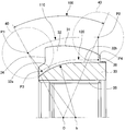
- FIG. (B) shows a part of the cage as a cross-sectional view in order to show a state in which the inner ring is inserted into the window portion of the cage.
- FIG. 1 is a cross-sectional view in the axial direction of the constant velocity joint 10 according to the present embodiment in a state where a predetermined joint operating angle ⁇ is taken.
- the opening side of the outer ring 20 means the left side of FIG. 1
- the back side of the outer ring 20 means the right side of FIG.
- the constant velocity joint 10 of the present embodiment is a joint center fixed ball type constant velocity joint (also referred to as “Zepper type constant velocity joint”), which is an outboard of a front drive shaft of an automobile. It is preferably used as a joint.
- the present invention can also be applied to a rear drive shaft.
- an undercut free type (UF) joint center fixed ball type constant velocity joint will be described as an example.
- the constant velocity joint 10 includes an outer ring 20 having a plurality of outer ring ball grooves 23, an inner ring 30 having a plurality of inner ring ball grooves 32, a plurality of balls 40, a cage 50, and a shaft 60. ing.
- an outer ring 20 having a plurality of outer ring ball grooves 23
- an inner ring 30 having a plurality of inner ring ball grooves 32
- a plurality of balls 40 a cage 50
- a shaft 60 a shaft 60.
- the outer ring 20 is formed in a cup shape (bottomed tubular shape) having an opening on the left side of FIG. 1 (corresponding to “one side in the axial direction” of the present invention).
- a connecting shaft 21 is integrally formed on the outer side (right side in FIG. 1) of the cup of the outer ring 20 so as to extend in the direction of the outer ring axis.
- the connecting shaft 21 is connected to another power transmission shaft.
- the inner peripheral surface of the outer ring 20 is formed in a concave spherical shape.
- the concave spherical inner peripheral surface 22 of the outer ring 20 is formed by a part of a spherical surface having an intersection O between the outer ring axis L1 and the inner ring axis L2 as a center of curvature, and is cut in the outer ring axis direction. When viewed in cross section, it is formed in a concave arc shape.
- outer ring ball grooves 23 whose outer ring axis orthogonal cross section is substantially concave arc-shaped are formed on the inner peripheral surface of the outer ring 20 so as to extend substantially in the outer ring axis direction.
- These outer ring ball grooves 23 (six in this embodiment) are formed at equal intervals in the circumferential direction (60-degree intervals in this embodiment) when viewed in a cross section cut in the radial direction.
- the outer ring axial direction means a direction passing through the central axis of the outer ring 20, that is, a rotation axis direction of the outer ring 20.
- the inner ring 30 is formed in an annular shape and is arranged inside the outer ring 20.
- the outer peripheral surface 31 of the inner ring 30 is formed in a convex spherical shape.
- the convex spherical outer peripheral surface 31 of the inner ring 30 is formed by a part of a spherical surface drawn with the intersection O between the outer ring axis L1 and the inner ring axis L2 as the center of curvature, and is a cross section cut in the direction of the inner ring axis. Is formed in a convex arc shape.
- a plurality of inner ring ball grooves 32 having a substantially arc-shaped cross section in the direction orthogonal to the inner ring axis are formed on the outer peripheral surface of the inner ring 30 so as to extend in the direction of the inner ring axis.
- the plurality of (six in this embodiment) inner ring ball grooves 32 are equally spaced in the circumferential direction (60 degrees in the present embodiment) and viewed from the outer ring 20 when viewed in a cross section cut in the radial direction.
- the same number of outer ring ball grooves 23 are formed. That is, each inner ring ball groove 32 is positioned so as to face each outer ring ball groove 23 of the outer ring 20.
- groove wall ridges 33 are formed which are constituted by the respective wall surfaces of these inner ring ball grooves 32 and project outward in the radial direction.
- a first notch 34 is provided on the convex spherical outer peripheral surface 31 side on one axial end side (left side in FIG. 1) of each groove wall ridge 33 toward the inner side in the radial direction.
- a second notch 36 is provided radially inward on the convex spherical outer peripheral surface 31 side on the other axial end side (right side in FIG. 1) of each groove wall protrusion 33.
- first notches 34 and the second notches 36 Due to the first notches 34 and the second notches 36, the axial length of the distal end portion in the radial direction of the groove wall protrusion 33 is shortened. Details of the first notch 34 and the second notch 36 will be described later with reference to FIG.
- the first notches 34 and the second notches 36 are formed in all the groove wall ridges 33, but may be formed only in one groove wall ridge 33.
- an inner spline 35 extending in the inner ring axial direction is formed on the inner peripheral surface of the inner ring 30.
- the internal spline 35 is fitted (engaged) with the external spline of the shaft 60.
- the inner ring axial direction means a direction passing through the central axis of the inner ring 30, that is, a rotation axis direction of the inner ring 30.
- the plurality of balls 40 are disposed so as to be sandwiched between the outer ring ball groove 23 of the outer ring 20 and the inner ring ball groove 32 of the inner ring 30 facing the outer ring ball groove 23, respectively.
- Each ball 40 is rotatable with respect to each outer ring ball groove 23 and each inner ring ball groove 32 and is engaged in a circumferential direction (around the outer ring axis or around the inner ring axis). Therefore, the ball 40 transmits torque between the outer ring 20 and the inner ring 30.
- the cage 50 is formed in an annular shape.
- the outer peripheral surface 51 of the cage 50 is formed in a partial spherical shape substantially corresponding to the concave spherical inner peripheral surface 22 of the outer ring 20, that is, a convex spherical shape.
- the inner peripheral surface 52 of the cage 50 is formed in a partial spherical shape that substantially corresponds to the convex spherical outer peripheral surface 31 of the inner ring 30, that is, a concave spherical shape.
- the cage 50 is disposed between the concave spherical inner peripheral surface 22 of the outer ring 20 and the convex spherical outer peripheral surface 31 of the inner ring 30.
- the cage 50 includes a plurality of window portions 53 that are substantially rectangular through holes arranged at equal intervals in the circumferential direction (the circumferential direction of the cage axis).
- the number of window portions 53 of the cage 50 is the same as the number of balls 40.
- One ball 40 is accommodated in each window 53.
- Four corners of each window 53 are formed in a circular arc concave shape. Thereby, the improvement of the intensity
- the groove bottom of the inner ring ball groove 32 is an arcuate curve drawn with the offset point b from the intersection O to the back side of the outer ring 20 (the right side in FIG. 1 and the right side in FIG. 2) as the center of curvature.
- the groove-shaped groove bottom 32a and the straight groove bottom 32b extending in the inner ring axial direction from one end of the curved groove bottom 32a are formed.
- the joint operating angle 100 capable of transmitting torque of the constant velocity joint 10 of the present embodiment that is, the angle formed between the outer ring 20 and the shaft 60 when the constant velocity joint 10 is in use is set in a range of 40 ° to 50 °, for example.
- FIG. 2 shows the range of arrows.
- the central locus 110 of the ball 40 when the ball 40 rolls in the inner ring ball groove 32 on one side (left side in FIG. 2) of the inner ring 30 in the joint operating angle 100 capable of transmitting torque is an arc shape. Is set to Further, on the other axial side of the inner ring 30 in the joint operating angle 100 (the right side in FIG.
- the center locus 110 of the ball 40 when the ball 40 rolls in the inner ring ball groove 32 is along the inner ring axial direction.
- the shape is set. That is, when the joint operating angle 100 is maximum, the center locus 110 of the ball 40 during torque transmission, which is the actual use state, is between P1 and P2.
- the inner ring ball groove 32 has a substantially arc-shaped cross section in the direction perpendicular to the inner ring axis.
- the inner ring ball groove 32 is formed, for example, in a so-called gothic arc shape in which two concave arc shapes having different centers are connected. Therefore, the contact locus 120 between the inner ring ball groove 32 and the ball 40, when viewed from the direction orthogonal to the axis of the inner ring 30, is shown by the groove bottoms 32a and 32b of the inner ring ball groove 32 as shown by the broken line in FIG. The position is shifted outward in the radial direction. Further, when viewed from the axial direction of the inner ring 30, the contact locus 120 between the inner ring ball groove 32 and the ball 40 becomes two places shifted in the circumferential direction in the inner ring ball groove 32 although not shown.
- the contact locus 120 between the inner ring ball groove 32 and the ball 40 is:
- the locus is indicated by a broken line in FIG. 2 (between P3 and P4). That is, the end point P3 on one side in the axial direction of the contact locus 120 (left side in FIG. 2) is located on a straight line connecting the end point P1 on the one side in the axial direction of the center locus 110 of the ball 40 and the offset point b.
- the end point P4 on the other side in the axial direction of the contact locus 120 (the right side in FIG.
- the contact locus 120 is substantially arcuate in the range where the inner ring ball groove 32 has a circular arc bottom (the range of the curved groove bottom 32a), and the inner ring ball groove 32 has a straight line bottom. In the range of the linear groove bottom 32b, it is substantially linear.
- the first notch 34 is formed at the end of a range in which the groove bottom of the inner ring ball groove 32 is an arcuate curve (range of the curved groove bottom 32a).
- the radially inner bottom portion of the first notch 34 is set to be positioned radially outward from the contact locus with the ball 40 in the inner ring ball groove 32. That is, the first notch 34 is formed so that the contact locus 120 between the inner ring ball groove 32 and the ball 40 is set at the axial position where the first notch 34 is formed.
- the second notch 36 is formed at the end of the range where the groove bottom of the inner ring ball groove 32 is linear (the range of the linear groove bottom 32b).
- the axial position where the second notch 36 is formed is set on the other side in the axial direction from the contact locus 120 between the inner ring ball groove 32 and the ball 40 during torque transmission. That is, the second notch 36 is formed on the other axial side (the right side in FIG. 2) than the end point P4 on the other axial side of the contact locus 120.
- the radially inner bottom portion of the second notch 36 is set to be located radially inward from the extended line of the contact locus 120 between the inner ring ball groove 32 and the ball 40.
- the extension line of the contact locus 120 is a line that is extended as it is while maintaining the curvature of the contact locus 120. That is, in the present embodiment, the contact locus 120 on the other side in the axial direction is a straight line, and thus is a straight line obtained by extending the straight line as it is.
- the radially inner bottom portion of the second notch 36 is located radially outward from the linear groove bottom 32 b of the inner ring ball groove 32 at the axial position of the inner ring 30 where the second notch 36 is formed. It is set to be. That is, the inner ring ball groove 32 is slightly formed at the axial position of the inner ring 30 where the second notch 36 is formed.
- the inner ring 30 configured as described above is assembled to the cage 50
- the axial direction of the inner ring 30 and the axial direction of the cage 50 are substantially orthogonal to each other.
- the inner ring ball groove 32 of the inner ring 30 is straddled across the inner ring ball groove 32 of the inner ring 30 on the introduction surface 54 formed on one end side (the right side of FIG. 3A) of the inner peripheral surface of the cage 50.
- the groove wall ridge 33 is inserted into the window 53.
- a first notch 34 is formed at one end side in the axial direction of the groove wall ridge portion 33 of the inner ring 30 (left side in FIG. 3B), and the axial direction of the groove wall ridge portion 33 of the inner ring 30.
- a second notch 36 is formed on the other end side (the right side in FIG. 3B). Therefore, one groove wall protrusion 33 of the inner ring 30 can be easily inserted into the window 53 of the retainer 50 without interfering with it.
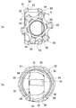
- the inner ring 30 is rotated in the direction indicated by the arrow X shown in FIG. 3A around the groove wall ridge 33 and inserted into the cage 50. Subsequently, after the center point of the convex spherical outer peripheral surface 31 of the inner ring 30 is aligned with the center point of the inner peripheral surface 52 of the cage 50, the inner ring 30 is rotated by 90 °, and the axial direction of the inner ring 30 and the cage 50. Match the axial direction. In this way, the convex spherical outer peripheral surface 31 of the inner ring 30 and the inner peripheral surface 52 of the retainer 50 are spherically engaged, whereby the assembly of the inner ring 30 and the retainer 50 is completed.
- the inner ring 30 and the cage 50 assembled in this way are arranged inside the outer ring 20. Subsequently, the balls 40 are inserted one by one into the outer ring ball groove 23, the inner ring ball groove 32 and the window portion 53 of the cage 50. Finally, the shaft 60 is inserted into the inner ring 30 to complete the assembly of the constant velocity joint 10.
- the constant velocity joint 10 of the same degree as in the conventional case.
- the groove wall protrusion 33 can be inserted deeper into the window 53 of the cage 50.
- the inner ring 30 can be assembled inside the cage 50.
- the pillar portion of the retainer 50 is not thinned, so that the strength and rigidity of the retainer 50 can be secured to the same level as in the past.
- the constant velocity joint 10 can be reduced in size while ensuring the strength and rigidity of the cage 50.
- the center locus 110 of the ball 40 has an arc shape on one side of the inner ring 30 in the axial direction, from the outer peripheral surface of the groove wall protrusion 33 before the formation of the first notch 34 to the curved groove bottom 32a.
- the distance is long enough. Even if the radial depth of the first notch 34 is made sufficiently deep, the contact locus 120 between the inner ring ball groove 32 and the ball 40 can be set.
- the radial depth of the first notch 34 of the groove wall ridge 33 on the one axial side is The inner ring 30 and the cage 50 can be assembled without setting so that the contact locus 120 between the inner ring ball groove 32 and the ball 40 cannot be secured.
- the joint operating angle 100 is changed to a predetermined angle (an angle required for the front drive shaft, for example, 40 ° to 50 °) and the outer diameter of the inner ring 30 is reduced compared to the conventional case.
- a predetermined angle an angle required for the front drive shaft, for example, 40 ° to 50 °
- the operation range of the ball 40 is shortened. This is clear from the relationship that the arc length around a certain point is longer as the radius is larger and shorter as the radius is smaller.
- an internal spline is formed on the inner peripheral surface of the inner ring 30 to enable torque transmission with the outer peripheral surface of the shaft 60. In order to transmit the necessary torque, the axial length of the internal spline 35 is determined by design.
- the axial length of the inner ring 30 is determined from the axial length of the internal splines 35. Accordingly, the outer diameter of the inner ring 30 is reduced to reduce the operating range of the ball.
- the axial length of the inner ring 30 is not different from the conventional one. Thus, there is a portion where the contact locus 120 between the ball 32 and the ball 40 may not be secured. Therefore, the second notch 36 is formed using this portion.
- the contact locus 120 between the inner ring ball groove 32 and the ball 40 is not set at the axial position where the second notch 36 is formed. Thereby, the radial direction depth of the 2nd notch 36 can be made deep enough. Also from this, even if the inner ring 30 and the cage 50 are downsized, the inner ring 30 and the cage 50 can be assembled.
- the center locus 110 of the ball 40 on the other side in the axial direction has a shape along the axial direction of the inner ring 30, that is, a linear shape.
- the groove depth of the inner ring ball groove 32 on the other axial side is shallower than the groove depth of the inner ring ball groove 32 on one axial side (left side in FIG. 2). ing. Therefore, if it is going to secure the contact locus 120, it is not easy to secure a sufficient radial depth of the second notch 36.
- the second notch 36 is formed without securing the contact locus 120 between the inner ring ball groove 32 and the ball 40, the second notch 36 having a deep radial depth can be formed.
- the inner ring 30 and the retainer 50 can be assembled even if the inner ring 30 and the retainer 50 are downsized by making the depth of the second cutout 36 in the radial direction as deep as possible.
- an undercut free type (UF) joint center fixed ball type constant velocity joint has been described.
- a bar field type (BF) joint center described in Japanese Patent Application Laid-Open No. 2008-008323 and the like is described.
- the first notch 34 and the second notch 36 can also be formed for the fixed ball type constant velocity joint.
- the inner ring 30 and the cage 50 can be assembled while reducing the size of the constant velocity joint.
- the inner ring 30 and the cage 50 can be assembled while reducing the size of the constant velocity joint. It becomes possible.
Landscapes
- Engineering & Computer Science (AREA)
- General Engineering & Computer Science (AREA)
- Mechanical Engineering (AREA)
- Rolling Contact Bearings (AREA)
Priority Applications (3)
| Application Number | Priority Date | Filing Date | Title |
|---|---|---|---|
| CN201180031557.6A CN102959261B (zh) | 2010-07-07 | 2011-07-04 | 滚珠式等速接头 |
| US13/807,834 US8808098B2 (en) | 2010-07-07 | 2011-07-04 | Ball type constant velocity joint |
| EP11803540.1A EP2592293B1 (en) | 2010-07-07 | 2011-07-04 | Ball type constant velocity joint |
Applications Claiming Priority (2)
| Application Number | Priority Date | Filing Date | Title |
|---|---|---|---|
| JP2010154645A JP5740857B2 (ja) | 2010-07-07 | 2010-07-07 | ボール型等速ジョイント |
| JP2010-154645 | 2010-07-07 |
Publications (1)
| Publication Number | Publication Date |
|---|---|
| WO2012005206A1 true WO2012005206A1 (ja) | 2012-01-12 |
Family
ID=45441185
Family Applications (1)
| Application Number | Title | Priority Date | Filing Date |
|---|---|---|---|
| PCT/JP2011/065262 Ceased WO2012005206A1 (ja) | 2010-07-07 | 2011-07-04 | ボール型等速ジョイント |
Country Status (5)
| Country | Link |
|---|---|
| US (1) | US8808098B2 (enExample) |
| EP (1) | EP2592293B1 (enExample) |
| JP (1) | JP5740857B2 (enExample) |
| CN (1) | CN102959261B (enExample) |
| WO (1) | WO2012005206A1 (enExample) |
Families Citing this family (2)
| Publication number | Priority date | Publication date | Assignee | Title |
|---|---|---|---|---|
| JP7102195B2 (ja) * | 2018-04-04 | 2022-07-19 | 株式会社ジェイテクト | 等速ジョイント |
| JP2023040443A (ja) * | 2021-09-10 | 2023-03-23 | 日立Astemo株式会社 | プロペラシャフト用の等速ジョイントおよびプロペラシャフト |
Citations (6)
| Publication number | Priority date | Publication date | Assignee | Title |
|---|---|---|---|---|
| JP2000145805A (ja) * | 1998-11-11 | 2000-05-26 | Nsk Ltd | 等速ジョイント及び等速ジョイント付自動車用ハブユニット |
| JP2000154833A (ja) | 1998-11-19 | 2000-06-06 | Toyoda Mach Works Ltd | 等速ジョイント |
| JP2005226732A (ja) * | 2004-02-12 | 2005-08-25 | Ntn Corp | 固定型等速自在継手 |
| JP2008008323A (ja) | 2006-06-27 | 2008-01-17 | Toyota Motor Corp | 等速継手 |
| JP2008309221A (ja) * | 2007-06-13 | 2008-12-25 | Ntn Corp | 固定式等速自在継手 |
| JP2009250365A (ja) * | 2008-04-08 | 2009-10-29 | Ntn Corp | 等速自在継手 |
Family Cites Families (6)
| Publication number | Priority date | Publication date | Assignee | Title |
|---|---|---|---|---|
| US5509857A (en) * | 1993-12-17 | 1996-04-23 | General Motors Corporation | Constant velocity universal joint |
| DE10032854C1 (de) * | 2000-07-06 | 2002-04-04 | Gkn Loebro Gmbh | Kugelgleichlaufdrehgelenk |
| US6817950B2 (en) * | 2002-11-14 | 2004-11-16 | Gkn Driveline North America, Inc. | High angle constant velocity joint |
| US7211002B2 (en) * | 2002-11-14 | 2007-05-01 | Gkn Driveline North America, Inc. | High angle constant velocity joint |
| US20050101391A1 (en) * | 2003-11-10 | 2005-05-12 | Ingalsbe Steven L. | Constant velocity joint having friction reducing web locators |
| DE102004023817A1 (de) * | 2004-05-13 | 2005-12-08 | Volkswagen Ag | Gleichlaufgelenk mit magnetischer Partikelsammelzone |
-
2010
- 2010-07-07 JP JP2010154645A patent/JP5740857B2/ja active Active
-
2011
- 2011-07-04 EP EP11803540.1A patent/EP2592293B1/en active Active
- 2011-07-04 CN CN201180031557.6A patent/CN102959261B/zh active Active
- 2011-07-04 US US13/807,834 patent/US8808098B2/en active Active
- 2011-07-04 WO PCT/JP2011/065262 patent/WO2012005206A1/ja not_active Ceased
Patent Citations (6)
| Publication number | Priority date | Publication date | Assignee | Title |
|---|---|---|---|---|
| JP2000145805A (ja) * | 1998-11-11 | 2000-05-26 | Nsk Ltd | 等速ジョイント及び等速ジョイント付自動車用ハブユニット |
| JP2000154833A (ja) | 1998-11-19 | 2000-06-06 | Toyoda Mach Works Ltd | 等速ジョイント |
| JP2005226732A (ja) * | 2004-02-12 | 2005-08-25 | Ntn Corp | 固定型等速自在継手 |
| JP2008008323A (ja) | 2006-06-27 | 2008-01-17 | Toyota Motor Corp | 等速継手 |
| JP2008309221A (ja) * | 2007-06-13 | 2008-12-25 | Ntn Corp | 固定式等速自在継手 |
| JP2009250365A (ja) * | 2008-04-08 | 2009-10-29 | Ntn Corp | 等速自在継手 |
Non-Patent Citations (1)
| Title |
|---|
| See also references of EP2592293A4 |
Also Published As
| Publication number | Publication date |
|---|---|
| EP2592293A1 (en) | 2013-05-15 |
| US20130172091A1 (en) | 2013-07-04 |
| JP5740857B2 (ja) | 2015-07-01 |
| JP2012017787A (ja) | 2012-01-26 |
| CN102959261B (zh) | 2015-05-20 |
| EP2592293A4 (en) | 2018-04-18 |
| US8808098B2 (en) | 2014-08-19 |
| CN102959261A (zh) | 2013-03-06 |
| EP2592293B1 (en) | 2020-05-06 |
Similar Documents
| Publication | Publication Date | Title |
|---|---|---|
| JP5740857B2 (ja) | ボール型等速ジョイント | |
| JP5355876B2 (ja) | 等速自在継手 | |
| JP5967185B2 (ja) | ボール型等速ジョイント | |
| JP5131064B2 (ja) | ボール型等速ジョイント | |
| JP5749912B2 (ja) | ダブルオフセット型等速ジョイント | |
| EP3418597B1 (en) | Stationary constant-velocity universal joint | |
| JP2010185538A (ja) | ボール型等速ジョイント | |
| JP2001349332A (ja) | 固定型等速自在継手およびその組立方法 | |
| JP5146769B2 (ja) | ボール型等速ジョイント | |
| JP2009121667A (ja) | 摺動式等速自在継手 | |
| JP2012017787A5 (enExample) | ||
| JP2011069404A (ja) | 固定式等速自在継手 | |
| US20080064509A1 (en) | Fixed Type Constant Velocity Universal Joint | |
| JP4896662B2 (ja) | 固定式等速自在継手 | |
| JP2015200377A (ja) | 等速ジョイント組立体 | |
| JP2006242263A (ja) | 固定型等速自在継手及びその製造方法 | |
| JP4624892B2 (ja) | 等速自在継手 | |
| JP2010249295A (ja) | 固定式等速自在継手およびその製造方法 | |
| JP2007132380A (ja) | 固定型等速自在継手 | |
| JP5398968B2 (ja) | 固定式等速自在継手 | |
| JP5299247B2 (ja) | ボール型等速ジョイント | |
| JP2009103182A (ja) | 固定式等速自在継手及びその製造方法 | |
| JP2007139064A (ja) | 摺動型等速自在継手 | |
| JP2004125045A (ja) | 等速自在継手 | |
| JP2007309493A (ja) | 等速自在継手 |
Legal Events
| Date | Code | Title | Description |
|---|---|---|---|
| WWE | Wipo information: entry into national phase |
Ref document number: 201180031557.6 Country of ref document: CN |
|
| 121 | Ep: the epo has been informed by wipo that ep was designated in this application |
Ref document number: 11803540 Country of ref document: EP Kind code of ref document: A1 |
|
| WWE | Wipo information: entry into national phase |
Ref document number: 2011803540 Country of ref document: EP |
|
| NENP | Non-entry into the national phase |
Ref country code: DE |
|
| WWE | Wipo information: entry into national phase |
Ref document number: 1201006522 Country of ref document: TH |
|
| WWE | Wipo information: entry into national phase |
Ref document number: 13807834 Country of ref document: US |