JP5355876B2 - 等速自在継手 - Google Patents
等速自在継手 Download PDFInfo
- Publication number
- JP5355876B2 JP5355876B2 JP2007276664A JP2007276664A JP5355876B2 JP 5355876 B2 JP5355876 B2 JP 5355876B2 JP 2007276664 A JP2007276664 A JP 2007276664A JP 2007276664 A JP2007276664 A JP 2007276664A JP 5355876 B2 JP5355876 B2 JP 5355876B2
- Authority
- JP
- Japan
- Prior art keywords
- joint member
- constant velocity
- velocity universal
- universal joint
- end surface
- Prior art date
- Legal status (The legal status is an assumption and is not a legal conclusion. Google has not performed a legal analysis and makes no representation as to the accuracy of the status listed.)
- Active
Links
Images


Classifications
-
- F—MECHANICAL ENGINEERING; LIGHTING; HEATING; WEAPONS; BLASTING
- F16—ENGINEERING ELEMENTS AND UNITS; GENERAL MEASURES FOR PRODUCING AND MAINTAINING EFFECTIVE FUNCTIONING OF MACHINES OR INSTALLATIONS; THERMAL INSULATION IN GENERAL
- F16D—COUPLINGS FOR TRANSMITTING ROTATION; CLUTCHES; BRAKES
- F16D3/00—Yielding couplings, i.e. with means permitting movement between the connected parts during the drive
- F16D3/16—Universal joints in which flexibility is produced by means of pivots or sliding or rolling connecting parts
- F16D3/20—Universal joints in which flexibility is produced by means of pivots or sliding or rolling connecting parts one coupling part entering a sleeve of the other coupling part and connected thereto by sliding or rolling members
- F16D3/22—Universal joints in which flexibility is produced by means of pivots or sliding or rolling connecting parts one coupling part entering a sleeve of the other coupling part and connected thereto by sliding or rolling members the rolling members being balls, rollers, or the like, guided in grooves or sockets in both coupling parts
- F16D3/223—Universal joints in which flexibility is produced by means of pivots or sliding or rolling connecting parts one coupling part entering a sleeve of the other coupling part and connected thereto by sliding or rolling members the rolling members being balls, rollers, or the like, guided in grooves or sockets in both coupling parts the rolling members being guided in grooves in both coupling parts
- F16D3/224—Universal joints in which flexibility is produced by means of pivots or sliding or rolling connecting parts one coupling part entering a sleeve of the other coupling part and connected thereto by sliding or rolling members the rolling members being balls, rollers, or the like, guided in grooves or sockets in both coupling parts the rolling members being guided in grooves in both coupling parts the groove centre-lines in each coupling part lying on a sphere
- F16D3/2245—Universal joints in which flexibility is produced by means of pivots or sliding or rolling connecting parts one coupling part entering a sleeve of the other coupling part and connected thereto by sliding or rolling members the rolling members being balls, rollers, or the like, guided in grooves or sockets in both coupling parts the rolling members being guided in grooves in both coupling parts the groove centre-lines in each coupling part lying on a sphere where the groove centres are offset from the joint centre
-
- F—MECHANICAL ENGINEERING; LIGHTING; HEATING; WEAPONS; BLASTING
- F16—ENGINEERING ELEMENTS AND UNITS; GENERAL MEASURES FOR PRODUCING AND MAINTAINING EFFECTIVE FUNCTIONING OF MACHINES OR INSTALLATIONS; THERMAL INSULATION IN GENERAL
- F16D—COUPLINGS FOR TRANSMITTING ROTATION; CLUTCHES; BRAKES
- F16D3/00—Yielding couplings, i.e. with means permitting movement between the connected parts during the drive
- F16D3/16—Universal joints in which flexibility is produced by means of pivots or sliding or rolling connecting parts
- F16D3/20—Universal joints in which flexibility is produced by means of pivots or sliding or rolling connecting parts one coupling part entering a sleeve of the other coupling part and connected thereto by sliding or rolling members
- F16D3/22—Universal joints in which flexibility is produced by means of pivots or sliding or rolling connecting parts one coupling part entering a sleeve of the other coupling part and connected thereto by sliding or rolling members the rolling members being balls, rollers, or the like, guided in grooves or sockets in both coupling parts
- F16D3/223—Universal joints in which flexibility is produced by means of pivots or sliding or rolling connecting parts one coupling part entering a sleeve of the other coupling part and connected thereto by sliding or rolling members the rolling members being balls, rollers, or the like, guided in grooves or sockets in both coupling parts the rolling members being guided in grooves in both coupling parts
- F16D2003/22313—Details of the inner part of the core or means for attachment of the core on the shaft
Description
12 内周面
14 トラック溝
20 内側継手部材
22 外周面
23 入口側端面
24 トラック溝
25 段差部
26 軸孔
27 凹端面
28 スプライン
28a スプライン端部
30 ボール
40 ケージ
L2 径方向寸法
m 非硬化層部分
Claims (6)
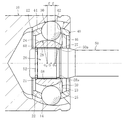
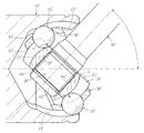
- 内周面に軸方向に延びる複数のトラック溝が形成された外側継手部材と、外周面に前記外側継手部材のトラック溝と対をなして軸方向に延びる複数のトラック溝が形成され、かつ、内周面に軸方向に延びるスプラインが形成された軸孔を有する内側継手部材と、前記外側継手部材のトラック溝と内側継手部材のトラック溝との間に介在してトルクを伝達する複数のボールと、前記外側継手部材の内周面と内側継手部材の外周面との間に介在してボールを保持するケージとを備え、
内側継手部材がシャフトの肩部との当接により位置決めされ、前記内側継手部材の入口側端面と前記軸孔のスプライン端部との間に軸方向の段差部が設けられ、前記段差部は、前記スプライン端部からトラック溝の底部に達し、かつ前記入口側端面よりも奥側に位置する凹端面を形成するものであり、前記凹端面の径方向寸法を1mm以上とし、最大作動角をとった時に、前記ボールと内側継手部材のトラック溝との間の接触楕円がトラック溝から食み出さず、かつ前記接触楕円の少なくとも一部が凹端面よりも入口側に食み出すようにしたことを特徴とする等速自在継手。 - 前記凹端面の径方向寸法を1.5mm以上とし、かつ、その凹端面が形成された内側継手部材端部に非硬化層部分が内在する請求項1に記載の等速自在継手。
- 前記ボールの個数が5〜8である請求項1又は2に記載の等速自在継手。
- 前記外側継手部材および内側継手部材のトラック溝は、鍛造仕上げで形成されている請求項1〜3のいずれか一項に記載の等速自在継手。
- 前記外側継手部材および内側継手部材は、軸方向に沿って円弧状をなすトラック溝が形成されている請求項1〜4のいずれか一項に記載の等速自在継手。
- 前記外側継手部材および内側継手部材は、軸方向に沿って直線部分を有するトラック溝が形成されている請求項1〜4のいずれか一項に記載の等速自在継手。
Priority Applications (5)
| Application Number | Priority Date | Filing Date | Title |
|---|---|---|---|
| JP2007276664A JP5355876B2 (ja) | 2007-10-24 | 2007-10-24 | 等速自在継手 |
| EP08842590.5A EP2202422B1 (en) | 2007-10-24 | 2008-09-24 | Constant velocity universal joint |
| US12/678,395 US8403764B2 (en) | 2007-10-24 | 2008-09-24 | Constant velocity universal joint |
| PCT/JP2008/067136 WO2009054216A1 (ja) | 2007-10-24 | 2008-09-24 | 等速自在継手 |
| CN200880112461.0A CN101836002B (zh) | 2007-10-24 | 2008-09-24 | 等速万向接头 |
Applications Claiming Priority (1)
| Application Number | Priority Date | Filing Date | Title |
|---|---|---|---|
| JP2007276664A JP5355876B2 (ja) | 2007-10-24 | 2007-10-24 | 等速自在継手 |
Publications (2)
| Publication Number | Publication Date |
|---|---|
| JP2009103250A JP2009103250A (ja) | 2009-05-14 |
| JP5355876B2 true JP5355876B2 (ja) | 2013-11-27 |
Family
ID=40579322
Family Applications (1)
| Application Number | Title | Priority Date | Filing Date |
|---|---|---|---|
| JP2007276664A Active JP5355876B2 (ja) | 2007-10-24 | 2007-10-24 | 等速自在継手 |
Country Status (5)
| Country | Link |
|---|---|
| US (1) | US8403764B2 (ja) |
| EP (1) | EP2202422B1 (ja) |
| JP (1) | JP5355876B2 (ja) |
| CN (1) | CN101836002B (ja) |
| WO (1) | WO2009054216A1 (ja) |
Families Citing this family (5)
| Publication number | Priority date | Publication date | Assignee | Title |
|---|---|---|---|---|
| DE102009011262B4 (de) * | 2009-03-02 | 2021-10-28 | Volkswagen Ag | Gleichlauffestgelenk |
| CN103334749B (zh) * | 2012-02-24 | 2018-08-07 | 刘素华 | 一种高效冲击防掰别的方法及实施该方法的高效冲击防掰别动力箱 |
| US11242896B2 (en) | 2017-07-19 | 2022-02-08 | Zhejiang Cfmoto Power Co. Ltd. | Spline slip constant velocity joint |
| US11125277B2 (en) | 2017-07-19 | 2021-09-21 | Zhejiang CFMOTO Power Co., Ltd. | Type of constant velocity universal joint with the spline slip structure |
| US10688639B2 (en) | 2018-04-24 | 2020-06-23 | Honda Motor Co., Ltd. | Front final gear assembly to propshaft clipping structure and installation method |
Family Cites Families (20)
| Publication number | Priority date | Publication date | Assignee | Title |
|---|---|---|---|---|
| US594587A (en) * | 1897-11-30 | Chuck | ||
| JPS5754723A (en) * | 1980-09-18 | 1982-04-01 | Toyota Motor Corp | Synchronized ball joint |
| US4813808A (en) * | 1983-08-19 | 1989-03-21 | Gkn Automotive Components Inc. | Axial retaining member and method for interconnecting male and female splined members |
| JPH0822801B2 (ja) | 1989-10-06 | 1996-03-06 | ウイスコンシン アラムナイ リサーチ フオンデーシヨン | 臓器保存用溶液 |
| JP3188001B2 (ja) | 1992-12-25 | 2001-07-16 | エヌティエヌ株式会社 | 等速自在継手の内輪と軸部との嵌合構造 |
| JPH08189533A (ja) * | 1995-01-12 | 1996-07-23 | Honda Motor Co Ltd | 等速自在継手 |
| CN1087817C (zh) * | 1995-12-26 | 2002-07-17 | 株式会社Ntn | 等速万向联轴节 |
| JP3702019B2 (ja) | 1995-12-26 | 2005-10-05 | Ntn株式会社 | 固定式等速ジョイント |
| DE19638780A1 (de) * | 1996-09-21 | 1998-04-02 | Loehr & Bromkamp Gmbh | Gleichlaufdrehgelenk mit Schmiermittelreservoir |
| DE19638779C1 (de) | 1996-09-21 | 1998-04-23 | Loehr & Bromkamp Gmbh | Gleichlaufdrehgelenk mit Schmiermittelreservoir |
| DE19802587C1 (de) * | 1998-01-23 | 1999-07-01 | Gkn Loebro Gmbh | Gleichlaufgelenk |
| JP2000145805A (ja) * | 1998-11-11 | 2000-05-26 | Nsk Ltd | 等速ジョイント及び等速ジョイント付自動車用ハブユニット |
| JP3909992B2 (ja) * | 1999-11-30 | 2007-04-25 | Ntn株式会社 | 固定式等速自在継手のケージおよびその製造方法並びに固定式等速自在継手 |
| JP2002013544A (ja) | 2000-06-27 | 2002-01-18 | Ntn Corp | 等速自在継手 |
| JP4516411B2 (ja) * | 2004-11-16 | 2010-08-04 | 本田技研工業株式会社 | 有内歯部材の製造方法 |
| JP2007032760A (ja) | 2005-07-28 | 2007-02-08 | Ntn Corp | 等速自在継手及びその内方部材 |
| JP2007064265A (ja) * | 2005-08-29 | 2007-03-15 | Ntn Corp | 等速自在継手及びその内方部材 |
| JP4584090B2 (ja) * | 2005-09-15 | 2010-11-17 | Ntn株式会社 | 複合型等速自在継手 |
| JP2007170575A (ja) * | 2005-12-22 | 2007-07-05 | Ntn Corp | 等速自在継手 |
| JP2008025641A (ja) * | 2006-07-19 | 2008-02-07 | Ntn Corp | 等速自在継手 |
-
2007
- 2007-10-24 JP JP2007276664A patent/JP5355876B2/ja active Active
-
2008
- 2008-09-24 CN CN200880112461.0A patent/CN101836002B/zh active Active
- 2008-09-24 US US12/678,395 patent/US8403764B2/en active Active
- 2008-09-24 WO PCT/JP2008/067136 patent/WO2009054216A1/ja active Application Filing
- 2008-09-24 EP EP08842590.5A patent/EP2202422B1/en active Active
Also Published As
| Publication number | Publication date |
|---|---|
| EP2202422A4 (en) | 2012-01-18 |
| EP2202422B1 (en) | 2014-08-20 |
| EP2202422A1 (en) | 2010-06-30 |
| US20100210368A1 (en) | 2010-08-19 |
| WO2009054216A1 (ja) | 2009-04-30 |
| US8403764B2 (en) | 2013-03-26 |
| CN101836002A (zh) | 2010-09-15 |
| JP2009103250A (ja) | 2009-05-14 |
| CN101836002B (zh) | 2015-07-01 |
Similar Documents
| Publication | Publication Date | Title |
|---|---|---|
| US8568245B2 (en) | Fixed type constant velocity universal joint | |
| EP2031262A1 (en) | Constant velocity universal joint | |
| US7651400B2 (en) | Constant velocity universal joint and inner member thereof | |
| JP5073190B2 (ja) | 摺動式等速自在継手 | |
| JP5355876B2 (ja) | 等速自在継手 | |
| US7258616B2 (en) | Fixed type constant velocity universal joint | |
| WO2009145034A1 (ja) | 固定型等速自在継手 | |
| JP2006266329A (ja) | 固定型等速自在継手 | |
| US8342971B2 (en) | Fixed type constant velocity universal joint | |
| JP2009174639A (ja) | 固定式等速自在継手 | |
| JP2009085326A (ja) | 等速自在継手 | |
| JP4896662B2 (ja) | 固定式等速自在継手 | |
| JP2007002943A (ja) | 等速自在継手及びその内方部材 | |
| JP2007162874A (ja) | 等速自在継手及びその内方部材 | |
| JP7292008B2 (ja) | 後輪用ドライブシャフト専用の摺動式等速自在継手 | |
| JP2007170423A (ja) | 等速自在継手及びその内方部材 | |
| JP5111817B2 (ja) | 固定式等速自在継手 | |
| JP2007064265A (ja) | 等速自在継手及びその内方部材 | |
| JP2010031910A (ja) | 等速自在継手の外側継手部材および等速自在継手 | |
| JP2007107568A (ja) | 固定式等速自在継手 | |
| JP4901530B2 (ja) | 等速自在継手 | |
| WO2018123394A1 (ja) | 固定式等速自在継手 | |
| JP2008261390A (ja) | 固定式等速自在継手 | |
| JP2007271040A (ja) | 固定式等速自在継手 | |
| JP2007263222A (ja) | 固定式等速自在継手 |
Legal Events
| Date | Code | Title | Description |
|---|---|---|---|
| A621 | Written request for application examination |
Free format text: JAPANESE INTERMEDIATE CODE: A621 Effective date: 20100906 |
|
| A131 | Notification of reasons for refusal |
Free format text: JAPANESE INTERMEDIATE CODE: A131 Effective date: 20121106 |
|
| A521 | Request for written amendment filed |
Free format text: JAPANESE INTERMEDIATE CODE: A523 Effective date: 20121217 |
|
| A02 | Decision of refusal |
Free format text: JAPANESE INTERMEDIATE CODE: A02 Effective date: 20130409 |
|
| A521 | Request for written amendment filed |
Free format text: JAPANESE INTERMEDIATE CODE: A523 Effective date: 20130709 |
|
| A911 | Transfer to examiner for re-examination before appeal (zenchi) |
Free format text: JAPANESE INTERMEDIATE CODE: A911 Effective date: 20130718 |
|
| TRDD | Decision of grant or rejection written | ||
| A01 | Written decision to grant a patent or to grant a registration (utility model) |
Free format text: JAPANESE INTERMEDIATE CODE: A01 Effective date: 20130809 |
|
| A61 | First payment of annual fees (during grant procedure) |
Free format text: JAPANESE INTERMEDIATE CODE: A61 Effective date: 20130828 |
|
| R150 | Certificate of patent or registration of utility model |
Ref document number: 5355876 Country of ref document: JP Free format text: JAPANESE INTERMEDIATE CODE: R150 Free format text: JAPANESE INTERMEDIATE CODE: R150 |
|
| R250 | Receipt of annual fees |
Free format text: JAPANESE INTERMEDIATE CODE: R250 |
|
| R250 | Receipt of annual fees |
Free format text: JAPANESE INTERMEDIATE CODE: R250 |
|
| R250 | Receipt of annual fees |
Free format text: JAPANESE INTERMEDIATE CODE: R250 |
|
| R250 | Receipt of annual fees |
Free format text: JAPANESE INTERMEDIATE CODE: R250 |
|
| R250 | Receipt of annual fees |
Free format text: JAPANESE INTERMEDIATE CODE: R250 |
|
| R250 | Receipt of annual fees |
Free format text: JAPANESE INTERMEDIATE CODE: R250 |
|
| R250 | Receipt of annual fees |
Free format text: JAPANESE INTERMEDIATE CODE: R250 |
|
| R250 | Receipt of annual fees |
Free format text: JAPANESE INTERMEDIATE CODE: R250 |