WO2012002105A1 - 燃料電池車両の暖房装置 - Google Patents
燃料電池車両の暖房装置 Download PDFInfo
- Publication number
- WO2012002105A1 WO2012002105A1 PCT/JP2011/062883 JP2011062883W WO2012002105A1 WO 2012002105 A1 WO2012002105 A1 WO 2012002105A1 JP 2011062883 W JP2011062883 W JP 2011062883W WO 2012002105 A1 WO2012002105 A1 WO 2012002105A1
- Authority
- WO
- WIPO (PCT)
- Prior art keywords
- fuel cell
- air
- heating
- passage
- hydrogen
- Prior art date
- Legal status (The legal status is an assumption and is not a legal conclusion. Google has not performed a legal analysis and makes no representation as to the accuracy of the status listed.)
- Ceased
Links
Images



Classifications
-
- B—PERFORMING OPERATIONS; TRANSPORTING
- B60—VEHICLES IN GENERAL
- B60H—ARRANGEMENTS OF HEATING, COOLING, VENTILATING OR OTHER AIR-TREATING DEVICES SPECIALLY ADAPTED FOR PASSENGER OR GOODS SPACES OF VEHICLES
- B60H1/00—Heating, cooling or ventilating devices
- B60H1/02—Heating, cooling or ventilating devices the heat being derived from the propulsion plant
- B60H1/14—Heating, cooling or ventilating devices the heat being derived from the propulsion plant other than from cooling liquid of the plant
-
- B—PERFORMING OPERATIONS; TRANSPORTING
- B60—VEHICLES IN GENERAL
- B60H—ARRANGEMENTS OF HEATING, COOLING, VENTILATING OR OTHER AIR-TREATING DEVICES SPECIALLY ADAPTED FOR PASSENGER OR GOODS SPACES OF VEHICLES
- B60H1/00—Heating, cooling or ventilating devices
- B60H1/22—Heating, cooling or ventilating devices the heat source being other than the propulsion plant
-
- H—ELECTRICITY
- H01—ELECTRIC ELEMENTS
- H01M—PROCESSES OR MEANS, e.g. BATTERIES, FOR THE DIRECT CONVERSION OF CHEMICAL ENERGY INTO ELECTRICAL ENERGY
- H01M8/00—Fuel cells; Manufacture thereof
- H01M8/04—Auxiliary arrangements, e.g. for control of pressure or for circulation of fluids
- H01M8/04007—Auxiliary arrangements, e.g. for control of pressure or for circulation of fluids related to heat exchange
- H01M8/04014—Heat exchange using gaseous fluids; Heat exchange by combustion of reactants
-
- H—ELECTRICITY
- H01—ELECTRIC ELEMENTS
- H01M—PROCESSES OR MEANS, e.g. BATTERIES, FOR THE DIRECT CONVERSION OF CHEMICAL ENERGY INTO ELECTRICAL ENERGY
- H01M8/00—Fuel cells; Manufacture thereof
-
- H—ELECTRICITY
- H01—ELECTRIC ELEMENTS
- H01M—PROCESSES OR MEANS, e.g. BATTERIES, FOR THE DIRECT CONVERSION OF CHEMICAL ENERGY INTO ELECTRICAL ENERGY
- H01M8/00—Fuel cells; Manufacture thereof
- H01M8/06—Combination of fuel cells with means for production of reactants or for treatment of residues
-
- B—PERFORMING OPERATIONS; TRANSPORTING
- B60—VEHICLES IN GENERAL
- B60H—ARRANGEMENTS OF HEATING, COOLING, VENTILATING OR OTHER AIR-TREATING DEVICES SPECIALLY ADAPTED FOR PASSENGER OR GOODS SPACES OF VEHICLES
- B60H1/00—Heating, cooling or ventilating devices
- B60H1/02—Heating, cooling or ventilating devices the heat being derived from the propulsion plant
- B60H1/14—Heating, cooling or ventilating devices the heat being derived from the propulsion plant other than from cooling liquid of the plant
- B60H1/143—Heating, cooling or ventilating devices the heat being derived from the propulsion plant other than from cooling liquid of the plant the heat being derived from cooling an electric component, e.g. electric motors, electric circuits, fuel cells or batteries
-
- H—ELECTRICITY
- H01—ELECTRIC ELEMENTS
- H01M—PROCESSES OR MEANS, e.g. BATTERIES, FOR THE DIRECT CONVERSION OF CHEMICAL ENERGY INTO ELECTRICAL ENERGY
- H01M2250/00—Fuel cells for particular applications; Specific features of fuel cell system
- H01M2250/20—Fuel cells in motive systems, e.g. vehicle, ship, plane
-
- Y—GENERAL TAGGING OF NEW TECHNOLOGICAL DEVELOPMENTS; GENERAL TAGGING OF CROSS-SECTIONAL TECHNOLOGIES SPANNING OVER SEVERAL SECTIONS OF THE IPC; TECHNICAL SUBJECTS COVERED BY FORMER USPC CROSS-REFERENCE ART COLLECTIONS [XRACs] AND DIGESTS
- Y02—TECHNOLOGIES OR APPLICATIONS FOR MITIGATION OR ADAPTATION AGAINST CLIMATE CHANGE
- Y02E—REDUCTION OF GREENHOUSE GAS [GHG] EMISSIONS, RELATED TO ENERGY GENERATION, TRANSMISSION OR DISTRIBUTION
- Y02E60/00—Enabling technologies; Technologies with a potential or indirect contribution to GHG emissions mitigation
- Y02E60/30—Hydrogen technology
- Y02E60/50—Fuel cells
-
- Y—GENERAL TAGGING OF NEW TECHNOLOGICAL DEVELOPMENTS; GENERAL TAGGING OF CROSS-SECTIONAL TECHNOLOGIES SPANNING OVER SEVERAL SECTIONS OF THE IPC; TECHNICAL SUBJECTS COVERED BY FORMER USPC CROSS-REFERENCE ART COLLECTIONS [XRACs] AND DIGESTS
- Y02—TECHNOLOGIES OR APPLICATIONS FOR MITIGATION OR ADAPTATION AGAINST CLIMATE CHANGE
- Y02T—CLIMATE CHANGE MITIGATION TECHNOLOGIES RELATED TO TRANSPORTATION
- Y02T90/00—Enabling technologies or technologies with a potential or indirect contribution to GHG emissions mitigation
- Y02T90/40—Application of hydrogen technology to transportation, e.g. using fuel cells
Definitions
- the present invention relates to a heating device for a fuel cell vehicle, and more particularly to a heating device for a fuel cell vehicle that heats the interior of the vehicle using an air-cooled fuel cell system.
- a fuel cell system mounted on a fuel cell vehicle generates electric power through an electrochemical reaction and generates water accompanying it.
- a fuel cell of a fuel cell system usually constitutes a fuel cell (stack) by laminating a number of minimum structural units called cells.
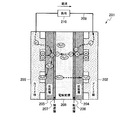
- a cell 201 is sandwiched between an anode electrode 202 and a cathode electrode 203 that supply hydrogen and air (oxygen), respectively, and diffusion layers 204 and 205 and reaction activity.
- Catalyst layers 206 and 207 for the formation of an electrolyte, and an electrolyte membrane 208 that selectively allows hydrogen ions to pass therethrough are arranged in the center.
- the hydrogen molecules supplied to the anode electrode 202 become active hydrogen atoms in the catalyst layer 206 on the surface of the electrolyte membrane 208 of the anode electrode 202, and further become hydrogen ions to release electrons.
- this reaction represented by (1) is represented by the following formula 1.
- H 2 ⁇ 2H + + 2e ⁇ (Formula 1)
- Hydrogen ions generated by Equation 1 move in the electrolyte membrane 208 from the anode electrode 202 side to the cathode electrode 203 side along with moisture contained in the electrolyte membrane 208, and electrons move to the cathode electrode 203 through the external circuit 209. To do.
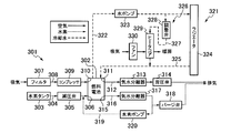
- FIG. 8 shows a configuration of a fuel cell system provided with the cell 201, which is a general water-cooled fuel cell system of a conventional fuel cell vehicle.
- a fuel cell system 301 shown in FIG. 8 includes a fuel cell 302 in which a large number of cells of the minimum structural unit are stacked, and compressed hydrogen gas stored in a high-pressure hydrogen tank 303 is passed through a pressure reducing valve 305 by an anode intake passage 304.
- the outside air introduced into the anode intake portion 306 of the fuel cell 302 and compressed into the cathode intake passage 308 through the filter 307 is compressed by the compressor 309 and introduced into the cathode intake portion 310 of the fuel cell 302. Power generation is performed in a plurality of stacked cells.
- Cathode exhaust exhausted from the cathode exhaust section 311 of the fuel cell 302 to the cathode exhaust passage 312 is separated from the water in the exhaust gas by the steam separator 313 and then used for pressure control of the cathode system. It is discharged to the outside air via the pressure valve 314.
- the anode exhaust exhausted from the anode exhaust part 315 of the fuel cell 302 to the anode exhaust passage 316 also passes through the steam separator 317, the purge valve 318, and the anode connected in the middle of the cathode exhaust passage 312. It is mixed into the cathode exhaust by the exhaust passage 316.
- the purge hydrogen exhaust amount from the anode exhaust unit 315 has a sufficiently small flow rate compared to the cathode exhaust amount. For this reason, the anode purge hydrogen can be discharged to the outside air at a flammable lower limit concentration of 4% or less by cathode exhaust.
- the anode exhaust passage 316 is connected to the anode intake portion 306 by the anode return passage 319, and the anode exhaust is discharged using the hydrogen pump 320 provided in the anode return passage 319. Some are recirculated to the anode intake 306.
- the cooling system 321 of the water-cooled fuel cell system 301 will be described.
- the cooling water introduction passage 322 of the cooling loop of the cooling system 321 is provided with a water pump 323 at the front stage or the rear stage of the fuel cell 302 to pump the cooling water to the radiator 324.
- the cooling water that has cooled the fuel cell 302 exchanges heat with the atmosphere in the radiator 324 and then returns to the fuel cell 302 again through the cooling water outlet passage 325 of the cooling loop.
- the cooling system 321 is provided with a heating device 326.
- the heating device 326 includes a heating passage 327 that connects the cooling water introduction passage 322 and the cooling water outlet passage 325, and a heater core for heating the vehicle interior via the adjustment valve 328 in parallel with the radiator 324 in the heating passage 327. 329.
- the heating device 326 supplies high-temperature cooling water to the heater core 329 by opening the adjustment valve 328 and drives the fan 330 for blowing air to provide heating in the vehicle interior.
- another auxiliary heat source such as an electric heater in addition to this.
- the water-cooled fuel cell vehicle system 301 includes a number of auxiliary devices including the compressor 309 that compresses the introduced air in order to improve the output density of the fuel cell 302. For this reason, the water-cooled fuel cell system 301 leads to a complicated, large, heavy, and expensive system.
- an air-cooled fuel cell system that simplifies the system by eliminating auxiliary equipment such as a compressor as much as possible, adopting an air-cooling method for cooling the fuel cell.
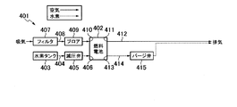
- an air-cooled fuel cell system 401 includes a fuel cell 402 in which a number of cells of the minimum structural unit are stacked, and compressed hydrogen gas stored in a high-pressure hydrogen tank 403 is reduced in the anode intake passage 404.
- the fuel cell system 401 does not have a high-pressure compression compressor in the cathode intake as in the case of a water-cooled fuel cell system in general, and external air sucked into the cathode intake passage 408 through the filter 407 is used as a low-pressure air supply fan. (Blower) 409 supplies to the cathode intake portion 410 of the fuel cell 402.
- the air supplied to the cathode intake section 410 is not only used for a power generation reaction in the cells stacked in the fuel cell 402 as a reaction gas with hydrogen, but also takes away waste heat in the fuel cell 402 and cools the fuel cell 402.
- the air after reaction with hydrogen and the air after cooling the fuel cell 402 are exhausted from the cathode exhaust part 411 of the fuel cell 402 to the cathode exhaust passage 412 and released to the outside air.
- the anode exhaust exhausted from the anode exhaust part 413 of the fuel cell 402 to the anode exhaust passage 414 passes through the purge valve 415 and is mixed into the cathode exhaust by the anode exhaust passage 414 connected in the middle of the cathode exhaust passage 412.
- the exhaust hydrogen gas is diluted to below the flammable lower limit concentration by the cathode side exhaust and released to the outside air. Since this air-cooled fuel cell system 401 does not have a cooling system 321 like the water-cooled fuel cell system 301 shown in FIG. 8, a heating device 326 similar to the water-cooled fuel cell system 301 is realized. I can't do it.
- a conventional fuel cell vehicle heating device directly discharges the cathode exhaust of the fuel cell into the vehicle interior (Patent Document 1), and directly discharges the cathode exhaust of the fuel cell into the vehicle interior and heats the vehicle interior heating device.
- Patent Document 2 There are those that lead to the exchanger (Patent Document 2) and those that guide the cathode exhaust of the fuel cell to the heat exchanger of the heating device in the passenger compartment (Patent Document 3).
- JP 2008-108538 A Japanese Patent Laid-Open No. 2002-5478 JP 2001-30742 A
- the waste heat generated by the fuel cell 302 in which a plurality of cells are stacked is the same as the waste heat of a vehicle engine.
- a water-cooled fuel cell system 301 that cools with cooling water is common.
- the cooling water having a relatively high temperature by cooling the fuel cell 302 is guided to the heater core 329 (heat exchanger) of the vehicle heating device 326.
- the waste heat is used for heating the passenger compartment.
- the water-cooled fuel cell system 301 unlike the water-cooled fuel cell system 301, as shown in FIG.
- an air-cooled fuel cell system 401 capable of realizing a very simple system configuration with a minimum of auxiliary machines is known.
- the fuel cell vehicle using the air-cooled fuel cell system 401 has a simple configuration and has many advantages such as small size, light weight, and low cost.
- the air-cooled fuel cell system 401 cannot use the waste heat of the cooling water of the fuel cell 402 for heating the passenger compartment, and there has been no proposal regarding an effective heating method or apparatus so far.
- the present invention is an air-cooled fuel cell that has a simple system configuration and can dilute the exhaust hydrogen gas in the anode exhaust of the fuel cell to below the lower flammable concentration and use the waste heat of the fuel cell system for heating.
- An object of the present invention is to realize a heating apparatus for a fuel cell vehicle capable of heating the vehicle interior using the system as it is.
- the present invention relates to a fuel cell that generates power by a chemical reaction between oxygen and hydrogen, and a cathode exhaust passage through which the introduced outside air is supplied to the cathode electrode of the fuel cell and used for the power generation reaction, and through which the air discharged from the fuel cell passes.
- a cathode exhaust passage through which hydrogen discharged from the fuel cell passes, and the air branched from the branch point of the cathode exhaust passage and supplied from the fuel cell to the vehicle compartment
- a branch passage is provided, and the anode exhaust passage is joined to the cathode exhaust passage downstream of the branch point.
- the heating device for a fuel cell vehicle according to the present invention can dilute the exhaust hydrogen gas in the anode exhaust to a flammable lower limit concentration or less, and can utilize the waste heat of the fuel cell system for heating the passenger compartment.
- the heating device for a fuel cell vehicle according to the present invention is a simple system configuration in which an air-cooled fuel cell system directly introduces cathode exhaust into a vehicle interior where heating is requested. Can do.
- the cathode exhaust is branched for heating and for purging hydrogen dilution, so that the exhaust hydrogen gas in the anode exhaust enters the vehicle compartment where heating is requested. Can be prevented.
- Example 1 It is a block diagram of the heating apparatus of a fuel cell vehicle.
- Example 1 It is a flowchart of the heating apparatus of a fuel cell vehicle.
- Example 1 It is a block diagram of the heating apparatus of a fuel cell vehicle.
- Example 2 It is a flowchart of the heating air flow rate adjustment of the heating apparatus of a fuel cell vehicle.
- Example 2 It is a flowchart of the heating blowing temperature adjustment of the heating apparatus of a fuel cell vehicle.
- Example 2 It is a block diagram of the heating apparatus of a fuel cell vehicle.
- (Modification) It is sectional drawing of the cell of a fuel cell. It is a block diagram of a water-cooled fuel cell system.
- Conventional example It is a block diagram of an air-cooled fuel cell system.
- Conventional example It is a block diagram of an air-cooled fuel cell system.
- reference numeral 1 denotes an air-cooled fuel cell system mounted on a fuel cell vehicle.
- the fuel cell system 1 includes the fuel cell 2 in which a large number of minimum structural units called cells are stacked, generates electric power by an electrochemical reaction, and generates water accompanying it.
- the compressed hydrogen gas stored in the high-pressure hydrogen tank 3 is lowered by the pressure reducing valve 5 in the anode intake passage 4 and then introduced into the anode intake portion 6 of the fuel cell 2.
- the fuel cell system 1 does not have a high-pressure compression compressor in the cathode intake air as in the case of a water-cooled fuel cell system in general, and the outside air sucked into the cathode intake passage 8 through the filter 7 is used as a low-pressure air supply fan. (Blower) 9 supplies the cathode intake portion 10 of the fuel cell 2.
- the air supplied to the cathode intake section 10 is not only used for the power generation reaction in the cells stacked in the fuel cell 2 as a reaction gas with hydrogen, but also takes away waste heat in the fuel cell 2 and cools the fuel cell 2. Have a role.
- the air after reaction with hydrogen and the air after cooling the fuel cell 2 are exhausted from the cathode exhaust part 11 of the fuel cell 2 to the cathode exhaust passage 12 and released to the outside air.
- the anode exhaust exhausted from the anode exhaust part 13 of the fuel cell 2 is introduced into the anode exhaust passage 14.
- the anode exhaust passage 14 is connected to the cathode exhaust passage 12 by providing a purge valve 15 in the middle.
- the anode exhaust in the anode exhaust passage 14 is mixed into the cathode exhaust in the cathode exhaust passage 12 via the purge valve 15.
- the fuel cell vehicle includes a heating device 16 that uses the waste heat of the fuel cell system 1.
- the heating device 16 is provided with a branch passage 18 that branches at a branch point 17 of the cathode exhaust passage 12, and an adjustment valve 19 is provided in the branch passage 18.
- the branch passage 18 communicates the cathode exhaust passage 12 with the vehicle interior via a regulating valve 19.
- the heating device 16 guides the cathode exhaust from the cathode exhaust passage 12 to the passenger compartment through the branch passage 18 and uses it for room heating.
- the anode exhaust passage 14 is connected to the cathode exhaust passage 12 downstream of the branch point 17 and is used for diluting the exhaust hydrogen gas of the anode exhaust.
- the regulating valve 19 is connected to the control unit 20 of the heating device 16.
- the control unit 20 is connected to a heating request input means 21 for inputting the presence / absence of a heating request by the operator's operation and the required amount of heat.
- the control unit 20 performs stepless opening / closing control of the regulating valve 19 disposed in the branch passage 18 based on the input of the heating request input means 21.
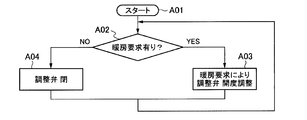
- the fuel cell vehicle heating device 16 determines whether there is a heating request from the heating request input means 21 (A02).
- this determination (A02) is YES
- the opening degree of the regulating valve 19 is adjusted steplessly according to the heating request (A03), and the process returns to the start (A01).
- the heating device 16 of the fuel cell vehicle is provided with the branch passage 18 that branches from the branch point 17 of the cathode exhaust passage 12 and supplies the air discharged from the fuel cell 2 to the vehicle compartment.
- the anode exhaust passage 14 is joined to the downstream cathode exhaust passage 12.
- the heating device 16 can dilute the exhaust hydrogen gas in the anode exhaust to a flammable lower limit concentration or less, and can use the waste heat of the fuel cell system 1 for heating the passenger compartment.
- the heating device 16 can be kept in a simple configuration because the cathode exhaust is directly introduced into the passenger compartment where heating is requested in the air-cooled fuel cell system 1 having a simple system configuration.
- the heating device 16 branches the cathode exhaust for heating and purging hydrogen dilution, it is possible to prevent the exhaust hydrogen gas in the anode exhaust from entering the vehicle interior where heating is requested. . Further, the heating device 16 is provided with an adjustment valve 19 in the branch passage 18 and changes the opening of the adjustment valve 19 so that the cathode exhaust flow rate changes according to the required heating amount. Therefore, the cathode exhaust according to the required heating amount. A flow rate can be obtained.
- the heating device 16 is provided with a hydrogen sensor 22 for detecting the hydrogen concentration in the passenger compartment, and the hydrogen sensor 22 is connected to the control unit 20. When the hydrogen sensor 22 detects hydrogen leakage, the control unit 20 adjusts the adjustment valve. By performing the 19 fully-closed control, it is possible to prevent hydrogen gas from leaking into the vehicle interior requested to be heated.
- FIG. 3 to 5 show Embodiment 2 of the present invention.
- the amount of heat that the exhaust after cooling of the fuel cell 2 of the fuel cell system 1 of the first embodiment has is smaller than the amount of heat that the cooling water after cooling of the fuel cell of the water-cooled fuel cell system has. It is often not enough as a heat source. For this reason, in Example 1 mentioned above, it may become inadequate as heating of a vehicle interior. In Example 2, the improvement when the heating of Example 1 becomes inadequate is aimed at.
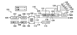
- reference numeral 101 denotes an air-cooled fuel cell system mounted on a fuel cell vehicle.
- the fuel cell system 101 according to the second embodiment includes a fuel cell 102 in which a large number of minimum structural units called cells are stacked.
- the fuel cell system 101 introduces the compressed hydrogen gas stored in the high-pressure hydrogen tank 103 into the anode intake portion 106 of the fuel cell 102 after reducing the pressure by the pressure reducing valve 105 in the anode intake passage 104.
- the fuel cell system 101 does not have a high-pressure compression compressor in the cathode intake as in the case of a water-cooled fuel cell system in general, and the outside air sucked into the cathode intake passage 108 through the filter 107 is used as a low-pressure air supply fan. (Blower) 109 supplies the cathode intake part 110 of the fuel cell 102.
- the air supplied to the cathode intake section 110 is not only used for the power generation reaction in the cells stacked in the fuel cell 102 as a reaction gas with hydrogen, but also takes away waste heat in the fuel cell 102 and cools the fuel cell 102. Have a role.
- the air after the reaction with hydrogen and the air after cooling the fuel cell 102 are exhausted from the cathode exhaust part 111 of the fuel cell 102 to the cathode exhaust passage 112 and released to the outside air.
- the anode exhaust exhausted from the anode exhaust part 113 of the fuel cell 102 is introduced into the anode exhaust passage 114.
- the anode exhaust passage 114 is connected to the cathode exhaust passage 112 with a purge valve 115 provided on the way.
- the anode exhaust in the anode exhaust passage 114 is mixed into the cathode exhaust in the cathode exhaust passage 112 through the purge valve 115.
- the exhaust hydrogen gas is diluted to below the flammable lower limit concentration by the cathode side exhaust and released to the outside air.
- the fuel cell vehicle includes a heating device 116 that uses the waste heat of the fuel cell system 101.
- the heating device 116 according to the second embodiment is provided with a branch passage 118 that branches at a branch point 117 of the cathode exhaust passage 112, and an adjustment valve 119 is provided in the branch passage 118.
- the branch passage 118 communicates the cathode exhaust passage 112 with the vehicle interior via the adjustment valve 119.
- the heating device 116 guides the cathode exhaust from the cathode exhaust passage 112 to the passenger compartment through the branch passage 118 and uses it for room heating.
- the anode exhaust passage 114 is connected to the cathode exhaust passage 112 on the downstream side of the branch point 117, and is used for diluting the exhaust hydrogen gas of the anode exhaust.
- the heating device 116 connects the outside air passage 121 that is open to the outside air to the junction 120 of the branch passage 118 on the downstream side of the regulating valve 119.
- the outside air passage 121 is provided with a push-in fan 122 for introducing outside air.
- the outside air passage 121 introduces the outside air introduced by the fan 122 into the branch passage 118 through the merging portion 120, joins the cathode exhaust that has passed through the regulating valve 119, and introduces it into the vehicle interior.
- the heating device 116 is provided with an electric heater 123 serving as an auxiliary heat source, such as a PTC heater, in the branch passage 118 on the downstream side of the junction 120.
- the regulating valve 119, the fan 122, and the electric heater 123 are connected to the control unit 124 of the heating device 116.
- the controller 124 is connected to an air flow rate detecting means 125 that detects the flow rate of air blown from the branch passage 118 into the vehicle interior, and detects the temperature of air blown from the branch passage 118 into the vehicle compartment.
- the means 126 is connected, and the heating request input means 127 for inputting the presence / absence of the heating request by the operation of the operator and the required amount of heat is connected.
- the air flow rate detection means 125 and the air temperature detection means 126 are provided in the heating blow-off portion 128 of the branch passage 118 in the vehicle interior.
- the control unit 124 compares the actual air flow rate detected by the air flow rate detection unit 125 with the target air flow rate based on the heating request amount set by the heating request input unit 127, and based on the comparison result, the control valve 119 The opening degree and the rotational speed of the fan 122 are changed. Further, the control unit 124 compares the actual air temperature detected by the air temperature detection unit 126 with the target air temperature based on the heating request amount set by the heating request input unit 127, and based on the comparison result, the electric heater The supply current to 123 is changed.
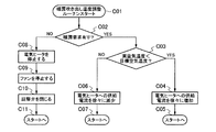
- the heating device 116 of the fuel cell vehicle adjusts the heating air flow rate as shown in FIG. 4 and also adjusts the heating blowing temperature as shown in FIG. These controls are processed in parallel by the control unit 124 as follows.
- this determination (B04) is YES, the rotational speed of the fan 124 is gradually increased (B07), and the process returns to the start (B01) (B08).
- the determination (B03) is NO, it is determined whether the fan 122 is stopped (B09). If this determination (B09) is YES, the regulating valve 119 is gradually closed (B10) and the process returns to the start (B01) (B11). When this determination (B09) is NO, the rotational speed of the fan 122 is gradually decreased (B12) and the process returns to the start (B01) (B13).
- the control unit 124 of the heating device 116 detects the heating request, the actual air flow rate measured by the air flow rate detection means 125 provided in the heating blowing unit 128 of the branch passage 118 in the vehicle interior, and the heating request input.
- the target air flow rate based on the operator's request by means 127 is compared.
- the control unit 124 increases the supply air flow rate by gradually opening the adjustment valve 119 if the adjustment valve 119 is not fully opened. If the flow rate is still insufficient even when the regulating valve 119 is fully open, the control unit 124 gradually increases the rotational speed of the fan 122 to increase the air flow rate.
- the control unit 124 gradually decreases the rotation speed if the fan 122 is rotating, and adjusts the fan 122 when the fan 122 is stopped. By gradually closing the valve 119, the actual air flow rate is controlled to match the target air flow rate.
- the heating request input means 127 the electric heater 123 and the fan 122 are stopped and the control valve 119 is controlled to close. Thereby, the heating device 116 of the fuel cell vehicle can change the air flow rate in accordance with the target air flow rate into the vehicle interior requested to be heated.
- the air flow rate detection means 125 may be omitted when the air flow rate can be predicted from the rotational speed of the fan 122 or the operation state of the fuel cell system 101. Is possible.
- the adjustment of the heating blowout temperature starts when the control of the heating blowout temperature adjustment by the control unit 124 is started (C01), and it is determined whether there is a heating request by the heating request input means 127 (C02). ).
- this determination (C02) is YES, it is determined whether the actual air temperature is lower than the target air temperature (C03).
- this determination (C03) is YES, the supply current to the electric heater 123 is gradually increased (C04), and the process returns to the start (C01) (C05).
- this determination (C03) is NO, the supply current to the electric heater 123 is gradually decreased (C06), and the process returns to the start (C01) (C07).
- the control unit 124 of the heating device 116 detects a heating request, the actual air temperature measured by the air temperature detection unit 126 provided in the heating blowing unit 128 and the operator's request by the heating request input unit 127. Compare the target air temperature based on When the actual air temperature is less than the target air temperature, the control unit 124 increases the blowing air temperature by gradually increasing the supply current to the electric heater 123. Conversely, when the actual air temperature exceeds the target air temperature, the control unit 124 gradually decreases the supply current to the electric heater 123 to lower the blown air temperature. When there is no heating request by the heating request input means 127, the electric heater 123 and the fan 122 are stopped and the control valve 119 is controlled to close. Thereby, the heating device 116 of the fuel cell vehicle can change the temperature of the blown air in accordance with the target air temperature for the vehicle interior requested to be heated.
- the cathode exhaust of the fuel cell system 101 will be described.
- the cathode exhaust of the fuel cell system 101 contains moisture generated due to the electrochemical reaction between hydrogen and oxygen, and therefore has a relatively high humidity as compared with intake air. Therefore, there is a concern about fogging of windows in the passenger compartment such as the front window during heating in the winter or rainy weather.
- the control unit 124 performs the following control in the heating device 116 for the fuel cell vehicle according to the second embodiment. That is, the heating device 116 is provided with window fogging detection means 129 that detects fogging of the front window of the passenger compartment, and is connected to the control unit 124.
- the control unit 124 reduces the cathode exhaust by setting the opening degree of the adjustment valve 119 to be equal to or less than the preset opening degree, and the outside air introduced by the fan 122. Increase the amount.
- the window fogging detection means 129 detects this, and when the fogging detection signal is transmitted to the control unit 124, the control unit 124 sets the maximum value of the regulating valve 119. Limit the opening to a certain threshold. By setting the threshold determined based on the piping diameter of the heating device 116, the relationship between the exhaust flow rate of the fuel cell 102 and the intake air flow rate by the fan 122, etc.
- the cathode exhaust flow rate of the fuel cell 102 The maximum value decreases. Thereby, the intake air flow rate by the fan 122 having a low temperature from the outside air is relatively increased, and fogging of the front window can be eliminated.
- the fogging detection signal input to the control unit 124 may be transmitted to the control unit 124 by an occupant who has visually detected clouding of the front window by operating some switch.
- a hydrogen sensor 130 for detecting the hydrogen concentration is provided in the passenger compartment, and when the hydrogen sensor 130 is connected to the control unit 124 and the hydrogen sensor 130 detects a hydrogen leak, By performing the fully closed control of the regulating valve 119 by the control unit 124, it is possible to prevent hydrogen gas from leaking into the vehicle interior where heating is requested.
- a push-type fan 122 for introducing outside air is provided in the outside air passage 121 in the previous stage of the electric heater 123.
- a suction-type fan 131 may be provided in the branch passage 118.
- the heating device 116 of the second embodiment directly introduces the cathode exhaust into the vehicle interior requested to be heated in the air-cooled fuel cell system 101 having a simple system configuration as in the first embodiment.
- the cathode exhaust can be branched for heating and purging hydrogen dilution, the exhaust hydrogen gas in the anode exhaust can be prevented from entering the vehicle interior where heating is required. be able to.
- the heating device 116 according to the second embodiment is provided with the adjusting valve 119 in the branch passage 118, and the opening degree of the adjusting valve 119 is changed so that the cathode exhaust gas flow rate changes according to the required heating amount. It is possible to obtain a cathode exhaust flow rate according to the above.
- the present invention relates to a heating device for a fuel cell system mounted on a fuel cell vehicle, but can also be applied to indoor heating using a stationary air-cooled fuel cell system such as for home use.
Landscapes
- Engineering & Computer Science (AREA)
- Chemical & Material Sciences (AREA)
- Electrochemistry (AREA)
- General Chemical & Material Sciences (AREA)
- Manufacturing & Machinery (AREA)
- Sustainable Development (AREA)
- Sustainable Energy (AREA)
- Chemical Kinetics & Catalysis (AREA)
- Life Sciences & Earth Sciences (AREA)
- Combustion & Propulsion (AREA)
- Physics & Mathematics (AREA)
- Thermal Sciences (AREA)
- Mechanical Engineering (AREA)
- Fuel Cell (AREA)
- Air-Conditioning For Vehicles (AREA)
- Electric Propulsion And Braking For Vehicles (AREA)
Abstract
Description
アノード極202に供給された水素分子は、アノード極202の電解質膜208の表面にある触媒層206において活性な水素原子となり、さらに水素イオンとなって電子を放出する。図7において、(1)で示されるこの反応は、以下の式1で表される。
・H2→2H++2e- (式1)
式1により発生した水素イオンは、電解質膜208に含まれる水分を伴ってアノード極202側からカソード極203側へと電解質膜208中を移動し、また電子は外部回路209を通じてカソード極203に移動する。この電子の移動により、外部回路209に介装された負荷(例えば、車両の走行用モータ)210には、電流が流れる。
一方、カソード極203に供給された空気中の酸素分子は、触媒層207において外部回路209から供給された電子を受け取り酸素イオンとなり、電解質膜208を移動してきた水素イオンと結合して水となる。図7において、(2)で示されるこの反応は、以下の式2で表される。
・1/2 02+2H++2e-→H20 (式2)
このようにして生成された水分の一部は、濃度拡散によりカソード極203からアノード極202へと移動する。
上述の化学反応において、セル201内部では電解質膜208や電極の電気抵抗に起因する抵抗過電圧、水素と酸素が電気化学反応を起こすための活性化過電圧、拡散層204,205中を水素や酸素が移動するための拡散過電圧など様々な損失が発生し、それにより発生した廃熱を冷却する必要がある。
燃料電池302のカソード排気部311からカソード排気通路312に排気されたカソード排気は、気水分離器313により排気中の水分の一部が分離された後、カソード系の圧力制御を目的とした背圧弁314を介して外気に放出される。また、燃料電池302のアノード排気部315からアノード排気通路316に排気されたアノード排気も同様に、気水分離器317を通り、パージ弁318を経て、カソード排気通路312の途中に接続されたアノード排気通路316によりカソード排気に混入される。
アノード排気部315からのパージ水素排気量は、カソード排気量に比べて十分に相対的に流量が小さい。このため、カソード排気により、アノードパージ水素を可燃下限濃度である4%以下として外気に放出することができる。なお、システムによっては、水素の利用率を向上させるため、アノード排気通路316をアノード吸気部306にアノード戻し通路319により接続し、アノード戻し通路319に設けた水素ポンプ320を用いて、アノード排気をアノード吸気部306に再循環させるものもある。
冷却システム321には、暖房装置326を設けている。暖房装置326は、冷却水導入通路322と冷却水導出通路325との間を接続する暖房通路327を備え、暖房通路327にラジエータ324と並列に調整弁328を介して車室内暖房のためのヒータコア329を備えている。暖房装置326は、暖房が必要な場合は調整弁328を開けることでヒータコア329に高温冷却水を供給し、送風のためのファン330を駆動することにより車室内の暖房に供する。ただし、燃料電池302の廃熱量は、エンジンが発生する廃熱量に比べて非常に小さいため、この他に電気ヒータなど他の補助熱源を併用するのが一般的である。
図9に示すように、空冷式の燃料電池システム401は、前述最小構成単位のセルを多数積層した燃料電池402を備え、高圧水素タンク403に貯蔵した圧縮水素ガスを、アノード吸気通路404の減圧弁405により降圧した後に燃料電池402のアノード吸気部406に導入する。一方、燃料電池システム401は、一般的に水冷式の燃料電池システムのようにカソード吸気における高圧圧縮コンプレッサを有さず、フィルタ407を通してカソード吸気通路408に吸気した外気を、低圧の空気供給用ファン(ブロア)409によって燃料電池402のカソード吸気部410に供給する。
カソード吸気部410に供給された空気は、水素との反応ガスとして燃料電池402内に多数積層したセルにおける発電反応に供するのみでなく、燃料電池402における廃熱を奪い、燃料電池402を冷却する役割を有している。水素との反応後の空気及び燃料電池402を冷却後の空気は、燃料電池402のカソード排気部411からカソード排気通路412に排気され、外気に放出される。燃料電池402のアノード排気部413からアノード排気通路414に排気されたアノード排気は、パージ弁415を経て、カソード排気通路412の途中に接続されたアノード排気通路414によりカソード排気に混入される。アノード側の水素ガスパージを行う際には、排気水素ガスをカソード側排気により可燃下限濃度以下に希釈して外気に放出される。
この空冷式の燃料電池システム401には、図8に示す水冷式の燃料電池システム301のような冷却システム321を有していないため、水冷式の燃料電池システム301と同様の暖房装置326を実現することはできない。
一方で、水冷式の燃料電池システム301と異なり、図9に示すよう、補機類を最小限として非常にシンプルなシステム構成を実現可能な空冷式の燃料電池システム401が知られている。空冷式の燃料電池システム401を用いた燃料電池車両は、その構成がシンプルであり、小型・軽量・低コストなどメリットが多い。
しかし、空冷式の燃料電池システム401は、車室内の暖房に燃料電池402の冷却水の廃熱を利用できず、これまでに有効な暖房方法・装置に関する提案がなかった。
また、この発明の燃料電池車両の暖房装置は、シンプルなシステム構成である空冷式の燃料電池システムにおいて、暖房要求された車室内にカソード排気を直接導入するので、シンプルな構成のままとすることができる。
さらに、この発明の燃料電池車両の暖房装置は、カソード排気を暖房用とパージ水素希釈用とに分岐させているので、アノード排気中の排気水素ガスが暖房要求された車室内に侵入することを防止することができる。
カソード吸気部10に供給された空気は、水素との反応ガスとして燃料電池2内に多数積層したセルにおける発電反応に供するのみでなく、燃料電池2における廃熱を奪い、燃料電池2を冷却する役割を有している。水素との反応後の空気及び燃料電池2を冷却後の空気は、燃料電池2のカソード排気部11からカソード排気通路12に排気され、外気に放出される。燃料電池2のアノード排気部13から排気されるアノード排気は、アノード排気通路14に導入される。アノード排気通路14は、途中にパージ弁15を配設し、カソード排気通路12に接続している。アノード排気通路14のアノード排気は、パージ弁15を経て、カソード排気通路12のカソード排気に混入される。アノード側の水素ガスパージを行う際には、排気水素ガスをカソード側排気により可燃下限濃度以下に希釈して外気に放出される。
前記調整弁19は、暖房装置16の制御部20に接続されている。制御部20には、操作者の操作による暖房の要求の有無および要求熱量を入力する暖房要求入力手段21を接続している。制御部20は、暖房要求入力手段21の入力に基づいて、分岐通路18に配設した調整弁19の無段階開閉制御を行う。
燃料電池車両の暖房装置16は、図2に示すように、制御部20の制御がスタートすると(A01)、暖房要求入力手段21による暖房要求が有るかを判断する(A02)。この判断(A02)がYESの場合は、暖房要求に応じて調整弁19の開度を無段階に調整し(A03)、スタート(A01)に戻る。この判断(A02)がNOの場合は、調整弁19を閉じ(A04)、スタート(A01)に戻る。なお、制御部20は、暖房要求入力手段21にる暖房要求が無くなると、調整弁19を閉じて制御をエンドにする。
これにより、暖房装置16は、アノード排気中の排気水素ガスを可燃下限濃度以下に希釈するとともに、燃料電池システム1の廃熱を車室の暖房に利用することができる。また、この暖房装置16は、シンプルなシステム構成である空冷式の燃料電池システム1において、暖房要求された車室内にカソード排気を直接導入するので、シンプルな構成のままとすることができる。さらに、この暖房装置16は、カソード排気を暖房用とパージ水素希釈用とに分岐させているので、アノード排気中の排気水素ガスが暖房要求された車室内に侵入することを防止することができる。
また、暖房装置16は、分岐通路18に調整弁19を設け、暖房要求量に応じてカソード排気流量が変わるように調整弁19の開度を変えるので、要求された暖房量に応じたカソード排気流量を得ることができる。
なお、暖房装置16は、車室内に水素濃度を検出する水素センサ22を設け、この水素センサ22を制御部20に接続し、水素センサ22が水素漏れを検知した時に、制御部20によって調整弁19の全閉制御を行うことで、水素ガスが暖房要求された車室内に漏れることを防ぐことができる。
上記実施例1の燃料電池システム1の燃料電池2の冷却後の排気が有する熱量は、水冷式の燃料電池システムの燃料電池の冷却後の冷却水が有する熱量に比較して小さく、車室内暖房の熱源としては十分でないことが多い。このため、上述した実施例1では、車室内の暖房としては不十分となる場合がある。実施例2においては、実施例1の暖房が不十分となる場合の改善を図っている。
図3において、101は燃料電池車両に搭載された空冷式の燃料電池システムである。実施例2の燃料電池システム101は、セルと呼ばれる最小構成単位を多数積層した燃料電池102を備えている。燃料電池システム101は、高圧水素タンク103に貯蔵した圧縮水素ガスを、アノード吸気通路104の減圧弁105により降圧した後に燃料電池102のアノード吸気部106に導入する。一方、燃料電池システム101は、一般的に水冷式の燃料電池システムのようにカソード吸気における高圧圧縮コンプレッサを有さず、フィルタ107を通してカソード吸気通路108に吸気した外気を、低圧の空気供給用ファン(ブロア)109によって燃料電池102のカソード吸気部110に供給する。
カソード吸気部110に供給された空気は、水素との反応ガスとして燃料電池102内に多数積層したセルにおける発電反応に供するのみでなく、燃料電池102における廃熱を奪い、燃料電池102を冷却する役割を有している。水素との反応後の空気及び燃料電池102を冷却後の空気は、燃料電池102のカソード排気部111からカソード排気通路112に排気され、外気に放出される。燃料電池102のアノード排気部113から排気されるアノード排気は、アノード排気通路114に導入される。アノード排気通路114は、途中にパージ弁115を配設し、カソード排気通路112に接続している。アノード排気通路114のアノード排気は、パージ弁115を経て、カソード排気通路112のカソード排気に混入される。アノード側の水素ガスパージを行う際には、排気水素ガスをカソード側排気により可燃下限濃度以下に希釈して外気に放出される。
また、暖房装置116は、調整弁119よりも下流側の分岐通路118の合流部120に、外気に開放した外気通路121を接続している。外気通路121には、外気を導入する押し込み型のファン122を設けている。外気通路121は、ファン122により導入された外気を、合流部120を経て分岐通路118に導入させ、調整弁119を通過したカソード排気と合流させ、車室内に導入する。さらに、暖房装置116は、合流部120よりも下流側の分岐通路118に、PTCヒータなど、補助熱源となる電気ヒータ123を設けている。
前記調整弁119と、ファン122と、電気ヒータ123とは、暖房装置116の制御部124に接続されている。制御部124には、分岐通路118から車室内へ吹き出される空気の流量を検出する空気流量検出手段125を接続し、分岐通路118から車室内へ吹き出される空気の温度を検出する空気温度検出手段126を接続し、操作者の操作による暖房の要求の有無および要求熱量を入力する暖房要求入力手段127を接続している。空気流量検出手段125及び空気温度検出手段126は、車室内の分岐通路118の暖房吹き出し部128に備えられている。
制御部124は、空気流量検出手段125により検出された実空気流量と暖房要求入力手段127により設定された暖房要求量に基づく目標空気流量とを比較し、この比較結果に基づいて調整弁119の開度とファン122の回転数とを変える。また、制御部124は、空気温度検出手段126により検出された実空気温度と暖房要求入力手段127により設定された暖房要求量に基づく目標空気温度とを比較し、この比較結果に基づいて電気ヒータ123への供給電流を変える。
この判断(B03)がYESの場合は、調整弁119が全開であるかを判断する(B04)。この判断(B04)がNOの場合は、調整弁119を徐々に開き(B05)、スタート(B01)に戻る(B06)。この判断(B04)がYESの場合は、ファン124の回転数を徐々に増加し(B07)、スタート(B01)に戻る(B08)。
これに対して、前記判断(B03)がNOの場合は、ファン122が停止しているかを判断する(B09)。この判断(B09)がYESの場合は、調整弁119を徐々に閉じ(B10)、スタート(B01)に戻る(B11)。この判断(B09)がNOの場合は、ファン122の回転数を徐々に減少し(B12)、スタート(B01)に戻る(B13)。
一方、前記判断(B02)がNOの場合は、電気ヒータ123を停止し(B14)、ファン122を停止し(B15)、調整弁119を閉じ(B16)、スタート(B01)に戻る(B17)。
逆に、制御部124は、実空気流量が目標空気流量よりも大きくなった場合、ファン122が回転中であれば、その回転数を徐々に低減させ、ファン122が停止している時には、調整弁119を徐々に閉じることにより実空気流量を目標空気流量に合わせるように制御する。暖房要求入力手段127による暖房要求が無い場合には、電気ヒータ123およびファン122を停止し、調整弁119は閉じるように制御する。
これにより、この燃料電池車両の暖房装置116は、暖房要求された車室内への目標空気流量に合わせて、空気流量を変えることができる。なお、暖房吹き出し部128に空気流量検出手段125を設けたが、ファン122の回転数や燃料電池システム101の運転状態から空気流量を予測可能な場合は、空気流量検出手段125を省略することが可能である。
この判断(C03)がYESの場合は、電気ヒータ123への供給電流を徐々に増加し(C04)、スタート(C01)に戻る(C05)。この判断(C03)がNOの場合は、電気ヒータ123への供給電流を徐々に減少し(C06)、スタート(C01)に戻る(C07)。
一方、前記判断(C02)がNOの場合は、電気ヒータ123を停止し(C08)、ファン122を停止し(C09)、調整弁119を閉じ(C10)、スタート(C01)に戻る(C11)。
これにより、この燃料電池車両の暖房装置116は、暖房要求された車室内への目標空気温度に合わせて、吹き出し空気温度を変えることができる。
この懸念を解決するため、実施例2の燃料電池車両の暖房装置116においては、制御部124により以下のような制御を行う。すなわち、暖房装置116は、車室のフロントウィンドウの曇りを検知するウィンドウ曇り検知手段129を設け、制御部124に接続する。制御部124は、ウィンドウ曇り検知手段129によりフロントウィンドウの曇りが検知された時には、調整弁119の開度を予め設定された開度以下にしてカソード排気を減少させ、ファン122により導入される外気量を増加させる。
このように、暖房装置116は、フロントウィンドウの曇りが発生し、それをウィンドウ曇り検知手段129が検知し、曇り検知信号が制御部124に伝達されると、制御部124によって調整弁119の最大開度をある特定の閾値に制限する。暖房装置116の配管径や、燃料電池102の排気流量とファン122による吸入空気流量との関係などから定められた閾値を調整弁119の最大開度とすることにより、燃料電池102のカソード排気流量最大値が減少する。それにより、外気からの温度の低いファン122による吸入空気流量が相対的に増加し、フロントウィンドウの曇りを解消することができる。なお、制御部124に入力される曇り検知信号は、フロントウィンドウの曇りを視覚的に検知した乗員が、何らかのスイッチを操作するなどにより制御部124に伝達される構成とすることもできる。
また、この実施例2の暖房装置116においては、車室内に水素濃度を検出する水素センサ130を設け、この水素センサ130を制御部124に接続し、水素センサ130が水素漏れを検知した時に、制御部124によって調整弁119の全閉制御を行うことで、水素ガスが暖房要求された車室内に漏れることを防ぐことができる。
なお、実施例2の燃料電池車両の暖房装置116においては、電気ヒータ123前段の外気通路121に外気導入用の押し込み型のファン122を設けたが、図6に示すように、電気ヒータ123後段の分岐通路118に吸い込み型のファン131を設けてもよい。
また、この実施例2の暖房装置116は、前述実施例1と同様に、シンプルなシステム構成である空冷式の燃料電池システム101において、暖房要求された車室内にカソード排気を直接導入するので、シンプルな構成のままとすることができ、カソード排気を暖房用とパージ水素希釈用とに分岐させているので、アノード排気中の排気水素ガスが暖房要求された車室内に侵入することを防止することができる。さらに、この実施例2の暖房装置116は、分岐通路118に調整弁119を設け、暖房要求量に応じてカソード排気流量が変わるように調整弁119の開度を変えるので、要求された暖房量に応じたカソード排気流量を得ることができる。
2 燃料電池
3 高圧水素タンク
4 アノード吸気通路
5 減圧弁
6 アノード吸気部
7 フィルタ
8 カソード吸気通路
9 空気供給用ファン
10 カソード吸気部
11 カソード排気部
12 カソード排気通路
13 アノード排気部
14 アノード排気通路
15 パージ弁
16 暖房装置
17 分岐点
18 分岐通路
19 調整弁
20 制御部
21 暖房要求入力手段
Claims (5)
- 酸素と水素との化学反応によって発電する燃料電池と、
導入した外気を前記燃料電池のカソード極に供給し発電反応に用いるとともに、前記燃料電池から排出された空気が通るカソード排気通路と前記燃料電池から排出された水素が通るアノード排気通路とを備えた燃料電池車両の暖房装置において、
前記カソード排気通路の分岐点から分岐し前記燃料電池から排出された空気を車室に供給する分岐通路を設け、
前記分岐点よりも下流側の前記カソード排気通路に前記アノード排気通路を合流させることを特徴とする燃料電池車両の暖房装置。 - 前記分岐通路に調整弁を設け、
暖房要求量に応じてカソード排気流量が変わるように前記調整弁の開度を変えることを特徴とする請求項1に記載の燃料電池車両の暖房装置。 - 車室内に水素濃度を測定する水素センサを設け、
前記水素センサにより水素漏れが検知された時には前記調整弁を全閉とすることを特徴とする請求項2に記載の燃料電池車両の暖房装置。 - 外気を導入するファンと、
前記ファンにより導入された外気と前記調整弁を通過したカソード排気とを合流させ、車室内に導入する通路と、
車室内への空気流量を検出する空気流量検出手段とを設け、
前記空気流量検出手段により検出された実空気流量と暖房要求量に基づく目標空気流量とを比較し、この比較結果に基づいて前記調整弁の開度と前記ファンの回転数とを変えることを特徴とする請求項2又は請求項3に記載の燃料電池車両の暖房装置。 - フロントウィンドウの曇りを検知するウィンドウ曇り検知手段を設け、
前記ウィンドウ曇り検知手段によりフロントウィンドウの曇りが検知された時には、前記調整弁の開度を予め設定された開度以下にし、前記ファンにより導入される外気量を増加させることを特徴とする請求項4に記載の燃料電池車両の暖房装置。
Priority Applications (4)
| Application Number | Priority Date | Filing Date | Title |
|---|---|---|---|
| US13/701,600 US9457640B2 (en) | 2010-07-02 | 2011-06-06 | Heating apparatus of fuel cell vehicle |
| GB1221013.4A GB2493872B (en) | 2010-07-02 | 2011-06-06 | Heating Apparatus of Fuel Cell Vehicle |
| DE112011102248.4T DE112011102248B4 (de) | 2010-07-02 | 2011-06-06 | Heizvorrichtung eines Brennstoffzellenfahrzeugs |
| CN201180031018.2A CN102985270B (zh) | 2010-07-02 | 2011-06-06 | 燃料电池车辆的加热设备 |
Applications Claiming Priority (2)
| Application Number | Priority Date | Filing Date | Title |
|---|---|---|---|
| JP2010-152049 | 2010-07-02 | ||
| JP2010152049A JP5812379B2 (ja) | 2010-07-02 | 2010-07-02 | 燃料電池車両の暖房装置 |
Publications (1)
| Publication Number | Publication Date |
|---|---|
| WO2012002105A1 true WO2012002105A1 (ja) | 2012-01-05 |
Family
ID=45401835
Family Applications (1)
| Application Number | Title | Priority Date | Filing Date |
|---|---|---|---|
| PCT/JP2011/062883 Ceased WO2012002105A1 (ja) | 2010-07-02 | 2011-06-06 | 燃料電池車両の暖房装置 |
Country Status (6)
| Country | Link |
|---|---|
| US (1) | US9457640B2 (ja) |
| JP (1) | JP5812379B2 (ja) |
| CN (1) | CN102985270B (ja) |
| DE (1) | DE112011102248B4 (ja) |
| GB (1) | GB2493872B (ja) |
| WO (1) | WO2012002105A1 (ja) |
Families Citing this family (25)
| Publication number | Priority date | Publication date | Assignee | Title |
|---|---|---|---|---|
| JP5812379B2 (ja) * | 2010-07-02 | 2015-11-11 | スズキ株式会社 | 燃料電池車両の暖房装置 |
| DE102013218958A1 (de) * | 2013-09-20 | 2015-03-26 | Bayerische Motoren Werke Aktiengesellschaft | Abgasanlage und Kraftfahrzeug mit Abgasanlage |
| JP2017503322A (ja) * | 2014-01-02 | 2017-01-26 | フィナジー リミテッド | ハイブリッド金属空気システムおよび方法 |
| DE102015200935A1 (de) * | 2015-01-21 | 2016-07-21 | Volkswagen Aktiengesellschaft | Brennstoffzellensystem, Fahrzeug mit einem solchen und Verfahren zum Betreiben des Brennstoffzellensystems und/oder des Fahrzeugs |
| DE102015222237A1 (de) * | 2015-11-11 | 2017-05-11 | Robert Bosch Gmbh | Brennstoffzelle |
| DE102015122144A1 (de) * | 2015-12-17 | 2017-06-22 | Volkswagen Ag | Befeuchter mit integriertem Wasserabscheider für ein Brennstoffzellensystem, Brennstoffzellensystem sowie Fahrzeug mit einem solchen |
| JP6852496B2 (ja) * | 2017-03-23 | 2021-03-31 | スズキ株式会社 | 燃料電池搭載車両 |
| US10871519B2 (en) | 2017-11-07 | 2020-12-22 | Toyota Motor Engineering & Manufacturing North America, Inc. | Fuel cell stack prediction utilizing IHOS |
| US10714767B2 (en) | 2017-12-07 | 2020-07-14 | Toyota Motor Engineering & Manufacturing North America, Inc. | Fuel cell air system safe operating region |
| US10590942B2 (en) | 2017-12-08 | 2020-03-17 | Toyota Motor Engineering & Manufacturing North America, Inc. | Interpolation of homotopic operating states |
| US10971748B2 (en) | 2017-12-08 | 2021-04-06 | Toyota Motor Engineering & Manufacturing North America, Inc. | Implementation of feedforward and feedback control in state mediator |
| US10665875B2 (en) | 2017-12-08 | 2020-05-26 | Toyota Motor Engineering & Manufacturing North America, Inc. | Path control concept |
| US11482719B2 (en) | 2017-12-08 | 2022-10-25 | Toyota Jidosha Kabushiki Kaisha | Equation based state estimate for air system controller |
| CN108134110A (zh) * | 2017-12-28 | 2018-06-08 | 东莞北京航空航天大学研究院 | 燃料电池双极板及其燃料电池,及风冷系统 |
| US10985391B2 (en) | 2018-03-06 | 2021-04-20 | Toyota Motor Engineering & Manufacturing North America, Inc. | Real time iterative solution using recursive calculation |
| US10547070B2 (en) | 2018-03-09 | 2020-01-28 | Toyota Motor Engineering & Manufacturing North America, Inc. | STL actuation-path planning |
| JP7127306B2 (ja) * | 2018-03-16 | 2022-08-30 | トヨタ自動車株式会社 | 車両及びその制御方法 |
| DE102018205555A1 (de) * | 2018-04-12 | 2019-10-17 | Audi Ag | Verfahren zum Anheben einer Temperatur eines Fahrzeuginnenraums und Fahrzeug zur Durchführung des Verfahrens |
| CN109037728B (zh) * | 2018-07-25 | 2023-10-27 | 浙江氢途科技有限公司 | 一种高可靠性燃料电池发动机 |
| JP2020100294A (ja) * | 2018-12-21 | 2020-07-02 | 本田技研工業株式会社 | 移動体 |
| GB2594893B (en) * | 2019-03-21 | 2022-05-18 | Intelligent Energy Ltd | Evaporatively cooled fuel cell systems with cathode exhaust turbine boost |
| CN112113009A (zh) * | 2020-10-19 | 2020-12-22 | 苏州钧峰新能源科技有限公司 | 一种燃料电池阴极出口单向阀 |
| CN112510223B (zh) * | 2021-02-07 | 2021-04-30 | 河南氢枫能源技术有限公司 | 一种氢燃料电池余热回收系统及方法 |
| US12253033B2 (en) * | 2022-10-04 | 2025-03-18 | General Electric Company | Hydrogen fuel leak detection system for a vehicle |
| DE102022128340A1 (de) * | 2022-10-26 | 2024-05-02 | Bayerische Motoren Werke Aktiengesellschaft | Energieversorgungssystem für ein Kraftfahrzeug, Kraftfahrzeug und Verfahren zum Betreiben eines Energieversorgungssystems |
Citations (3)
| Publication number | Priority date | Publication date | Assignee | Title |
|---|---|---|---|---|
| JPS63243664A (ja) * | 1986-11-07 | 1988-10-11 | 株式会社デンソー | 冷・温熱発生装置 |
| JP2006035885A (ja) * | 2004-07-22 | 2006-02-09 | Denso Corp | 車両用空気浄化装置および当該装置を備える車両用空気浄化システム |
| JP2009266472A (ja) * | 2008-04-23 | 2009-11-12 | Toyota Motor Corp | 燃料電池を備えた移動体の暖房システム |
Family Cites Families (33)
| Publication number | Priority date | Publication date | Assignee | Title |
|---|---|---|---|---|
| DE3812812C1 (ja) * | 1988-04-16 | 1989-10-19 | Mtu Friedrichshafen Gmbh | |
| JP4266255B2 (ja) * | 1999-07-21 | 2009-05-20 | サンデン株式会社 | 自動車用空気調和装置 |
| JP4061820B2 (ja) * | 1999-10-20 | 2008-03-19 | 株式会社デンソー | 冷凍サイクル装置 |
| JP2002005478A (ja) * | 2000-06-23 | 2002-01-09 | Matsushita Electric Ind Co Ltd | 空気調和機 |
| JP4374799B2 (ja) * | 2001-05-17 | 2009-12-02 | 株式会社デンソー | 燃料電池自動車 |
| JP2004166488A (ja) | 2002-10-22 | 2004-06-10 | Nissan Motor Co Ltd | 燃料電池車両 |
| JP4352682B2 (ja) * | 2002-10-23 | 2009-10-28 | 日産自動車株式会社 | 燃料電池車用暖房システム |
| CN2652694Y (zh) | 2003-06-24 | 2004-11-03 | 邬益飞 | 车用空气温湿度调节装置 |
| JP2005158509A (ja) * | 2003-11-26 | 2005-06-16 | Nissan Motor Co Ltd | 燃料電池システム |
| DE502005004377D1 (de) | 2004-07-09 | 2008-07-24 | Bayerische Motoren Werke Ag | System aus Brennstoffzelle, Nachbrenner und Wärmetauscher |
| DE102004033545B4 (de) | 2004-07-09 | 2006-06-14 | J. Eberspächer GmbH & Co. KG | Brenner |
| KR100612912B1 (ko) * | 2004-12-15 | 2006-08-14 | 삼성에스디아이 주식회사 | 직접액체연료전지용 연료공급장치 |
| JP4667985B2 (ja) * | 2005-07-07 | 2011-04-13 | 本田技研工業株式会社 | 排出燃料希釈器 |
| SE529344C2 (sv) | 2005-11-28 | 2007-07-10 | Scania Cv Abp | Aggregat för ventilering och luftkonditionering av ett förarutrymme hos ett motorfordon |
| EP2008330A4 (en) * | 2006-04-07 | 2009-12-23 | Utc Power Corp | OPERATION OF A FUEL CELL DURING A DECAY TIME IN CRYOGENIC HYDROGEN DISPENSE |
| US9614236B2 (en) * | 2006-08-10 | 2017-04-04 | GM Global Technology Operations LLC | Method for mitigating cell degradation due to startup and shutdown via cathode re-circulation combined with electrical shorting of stack |
| JP2008108538A (ja) * | 2006-10-25 | 2008-05-08 | Toyota Motor Corp | 燃料電池システム |
| JP4530176B2 (ja) * | 2006-10-26 | 2010-08-25 | トヨタ自動車株式会社 | 燃料電池車両 |
| JP5446065B2 (ja) * | 2006-11-24 | 2014-03-19 | トヨタ自動車株式会社 | 燃料電池と空調の協調冷却システム |
| DE102007006963A1 (de) * | 2007-02-13 | 2008-08-14 | Daimler Ag | Brennstoffzellensystem für ein Fahrzeug |
| US8011598B2 (en) * | 2007-04-18 | 2011-09-06 | Delphi Technologies, Inc. | SOFC power system with A/C system and heat pump for stationary and transportation applications |
| JP5214190B2 (ja) * | 2007-08-01 | 2013-06-19 | 本田技研工業株式会社 | 燃料電池システム及びその運転方法 |
| US8113034B2 (en) * | 2007-10-12 | 2012-02-14 | Honda Motor Co., Ltd. | Gas sensor with piping for the introduction of inspection gas |
| DK2212957T3 (en) * | 2007-10-22 | 2017-01-23 | Hydrogenics Corp | VENTILATION FOR POWER SUPPLY IN STATIVE |
| JP4597180B2 (ja) * | 2007-11-06 | 2010-12-15 | 本田技研工業株式会社 | 車両用空調システム |
| JP4463846B2 (ja) * | 2007-11-13 | 2010-05-19 | 本田技研工業株式会社 | 水素製造発電システム |
| JP2009140872A (ja) * | 2007-12-10 | 2009-06-25 | Toyota Motor Corp | 燃料電池システム及びそれを備えた燃料電池車 |
| JP2011508947A (ja) * | 2007-12-28 | 2011-03-17 | ユーティーシー パワー コーポレイション | 起動時の燃料電池セルのカソードにおける水素の燃焼 |
| US20100035098A1 (en) * | 2008-08-06 | 2010-02-11 | Manikandan Ramani | Using chemical shorting to control electrode corrosion during the startup or shutdown of a fuel cell |
| US8603690B2 (en) * | 2008-12-12 | 2013-12-10 | GM Global Technology Operations LLC | Methods and controls for hydrogen to cathode inlet of a fuel cell system |
| US8697303B2 (en) * | 2010-01-25 | 2014-04-15 | GM Global Technology Operations LLC | Optimized cathode fill strategy for fuel cell |
| JP5812379B2 (ja) * | 2010-07-02 | 2015-11-11 | スズキ株式会社 | 燃料電池車両の暖房装置 |
| KR101889579B1 (ko) * | 2011-02-25 | 2018-08-17 | 아우디 아게 | 전력 이행 및 아이들링 중의 pem 연료 전지 전압 제어 |
-
2010
- 2010-07-02 JP JP2010152049A patent/JP5812379B2/ja active Active
-
2011
- 2011-06-06 US US13/701,600 patent/US9457640B2/en active Active
- 2011-06-06 CN CN201180031018.2A patent/CN102985270B/zh not_active Expired - Fee Related
- 2011-06-06 DE DE112011102248.4T patent/DE112011102248B4/de active Active
- 2011-06-06 WO PCT/JP2011/062883 patent/WO2012002105A1/ja not_active Ceased
- 2011-06-06 GB GB1221013.4A patent/GB2493872B/en active Active
Patent Citations (3)
| Publication number | Priority date | Publication date | Assignee | Title |
|---|---|---|---|---|
| JPS63243664A (ja) * | 1986-11-07 | 1988-10-11 | 株式会社デンソー | 冷・温熱発生装置 |
| JP2006035885A (ja) * | 2004-07-22 | 2006-02-09 | Denso Corp | 車両用空気浄化装置および当該装置を備える車両用空気浄化システム |
| JP2009266472A (ja) * | 2008-04-23 | 2009-11-12 | Toyota Motor Corp | 燃料電池を備えた移動体の暖房システム |
Also Published As
| Publication number | Publication date |
|---|---|
| DE112011102248T5 (de) | 2013-05-02 |
| JP5812379B2 (ja) | 2015-11-11 |
| DE112011102248B4 (de) | 2020-11-26 |
| GB201221013D0 (en) | 2013-01-09 |
| US20130087305A1 (en) | 2013-04-11 |
| GB2493872A (en) | 2013-02-20 |
| CN102985270A (zh) | 2013-03-20 |
| JP2012011942A (ja) | 2012-01-19 |
| GB2493872B (en) | 2015-11-04 |
| US9457640B2 (en) | 2016-10-04 |
| CN102985270B (zh) | 2015-09-02 |
Similar Documents
| Publication | Publication Date | Title |
|---|---|---|
| JP5812379B2 (ja) | 燃料電池車両の暖房装置 | |
| KR101113651B1 (ko) | 연료전지 차량의 수소 배기 장치 | |
| CN101517801B (zh) | 燃料电池系统 | |
| US10115984B2 (en) | Integrated recirculating open cathode fuel cell system | |
| JP5387762B2 (ja) | 燃料電池システム及び燃料電池の熱を利用して暖房を行なう方法 | |
| CN102986073B (zh) | 空冷式燃料电池的吸气设备 | |
| WO2012029414A1 (ja) | 燃料電池システム | |
| US20130139997A1 (en) | Air-cooled fuel cell vehicle | |
| US7371477B2 (en) | Exhaust gas processing device for fuel cell | |
| WO2009005169A1 (ja) | 燃料電池システム及びその制御方法 | |
| KR20120062060A (ko) | 연료전지 차량 | |
| KR102335975B1 (ko) | 연료전지 시스템 | |
| JP4403702B2 (ja) | 燃料電池システムの制御装置 | |
| JP2004179102A (ja) | 燃料電池の排出ガス処理装置の制御方法 | |
| WO2010070881A1 (ja) | 燃料電池システム、およびその起動時における開弁動作の制御方法 | |
| JP5835151B2 (ja) | 燃料電池システム | |
| JP2008288038A (ja) | 燃料電池の掃気方法、加湿器、及び燃料電池システム | |
| JP5583536B2 (ja) | 燃料電池システムの運転停止方法 | |
| JP2006079847A (ja) | ガス漏れ検知装置 | |
| JP5142006B2 (ja) | 燃料電池システム | |
| KR20220148467A (ko) | 연료전지 시스템 및 그것의 동작 방법 | |
| JP2008041549A (ja) | 燃料電池システム及び燃料電池車両 | |
| JP2007123031A (ja) | 燃料電池システム | |
| JP2008053112A (ja) | 燃料電池システム | |
| JP2008112694A (ja) | 燃料電池システム |
Legal Events
| Date | Code | Title | Description |
|---|---|---|---|
| WWE | Wipo information: entry into national phase |
Ref document number: 201180031018.2 Country of ref document: CN |
|
| 121 | Ep: the epo has been informed by wipo that ep was designated in this application |
Ref document number: 11800573 Country of ref document: EP Kind code of ref document: A1 |
|
| ENP | Entry into the national phase |
Ref document number: 1221013 Country of ref document: GB Kind code of ref document: A Free format text: PCT FILING DATE = 20110606 |
|
| WWE | Wipo information: entry into national phase |
Ref document number: 1221013.4 Country of ref document: GB |
|
| WWE | Wipo information: entry into national phase |
Ref document number: 9972/CHENP/2012 Country of ref document: IN |
|
| WWE | Wipo information: entry into national phase |
Ref document number: 13701600 Country of ref document: US |
|
| WWE | Wipo information: entry into national phase |
Ref document number: 112011102248 Country of ref document: DE Ref document number: 1120111022484 Country of ref document: DE |
|
| 122 | Ep: pct application non-entry in european phase |
Ref document number: 11800573 Country of ref document: EP Kind code of ref document: A1 |