WO2011158353A1 - 内燃機関の燃料制御装置 - Google Patents
内燃機関の燃料制御装置 Download PDFInfo
- Publication number
- WO2011158353A1 WO2011158353A1 PCT/JP2010/060238 JP2010060238W WO2011158353A1 WO 2011158353 A1 WO2011158353 A1 WO 2011158353A1 JP 2010060238 W JP2010060238 W JP 2010060238W WO 2011158353 A1 WO2011158353 A1 WO 2011158353A1
- Authority
- WO
- WIPO (PCT)
- Prior art keywords
- fuel
- internal combustion
- combustion engine
- air
- exhaust
- Prior art date
Links
Images


Classifications
-
- F—MECHANICAL ENGINEERING; LIGHTING; HEATING; WEAPONS; BLASTING
- F02—COMBUSTION ENGINES; HOT-GAS OR COMBUSTION-PRODUCT ENGINE PLANTS
- F02D—CONTROLLING COMBUSTION ENGINES
- F02D19/00—Controlling engines characterised by their use of non-liquid fuels, pluralities of fuels, or non-fuel substances added to the combustible mixtures
- F02D19/06—Controlling engines characterised by their use of non-liquid fuels, pluralities of fuels, or non-fuel substances added to the combustible mixtures peculiar to engines working with pluralities of fuels, e.g. alternatively with light and heavy fuel oil, other than engines indifferent to the fuel consumed
- F02D19/0602—Control of components of the fuel supply system
- F02D19/0613—Switch-over from one fuel to another
- F02D19/0615—Switch-over from one fuel to another being initiated by automatic means, e.g. based on engine or vehicle operating conditions
-
- F—MECHANICAL ENGINEERING; LIGHTING; HEATING; WEAPONS; BLASTING
- F02—COMBUSTION ENGINES; HOT-GAS OR COMBUSTION-PRODUCT ENGINE PLANTS
- F02D—CONTROLLING COMBUSTION ENGINES
- F02D19/00—Controlling engines characterised by their use of non-liquid fuels, pluralities of fuels, or non-fuel substances added to the combustible mixtures
- F02D19/06—Controlling engines characterised by their use of non-liquid fuels, pluralities of fuels, or non-fuel substances added to the combustible mixtures peculiar to engines working with pluralities of fuels, e.g. alternatively with light and heavy fuel oil, other than engines indifferent to the fuel consumed
- F02D19/0639—Controlling engines characterised by their use of non-liquid fuels, pluralities of fuels, or non-fuel substances added to the combustible mixtures peculiar to engines working with pluralities of fuels, e.g. alternatively with light and heavy fuel oil, other than engines indifferent to the fuel consumed characterised by the type of fuels
- F02D19/0642—Controlling engines characterised by their use of non-liquid fuels, pluralities of fuels, or non-fuel substances added to the combustible mixtures peculiar to engines working with pluralities of fuels, e.g. alternatively with light and heavy fuel oil, other than engines indifferent to the fuel consumed characterised by the type of fuels at least one fuel being gaseous, the other fuels being gaseous or liquid at standard conditions
- F02D19/0647—Controlling engines characterised by their use of non-liquid fuels, pluralities of fuels, or non-fuel substances added to the combustible mixtures peculiar to engines working with pluralities of fuels, e.g. alternatively with light and heavy fuel oil, other than engines indifferent to the fuel consumed characterised by the type of fuels at least one fuel being gaseous, the other fuels being gaseous or liquid at standard conditions the gaseous fuel being liquefied petroleum gas [LPG], liquefied natural gas [LNG], compressed natural gas [CNG] or dimethyl ether [DME]
-
- F—MECHANICAL ENGINEERING; LIGHTING; HEATING; WEAPONS; BLASTING
- F02—COMBUSTION ENGINES; HOT-GAS OR COMBUSTION-PRODUCT ENGINE PLANTS
- F02D—CONTROLLING COMBUSTION ENGINES
- F02D41/00—Electrical control of supply of combustible mixture or its constituents
- F02D41/0025—Controlling engines characterised by use of non-liquid fuels, pluralities of fuels, or non-fuel substances added to the combustible mixtures
-
- F—MECHANICAL ENGINEERING; LIGHTING; HEATING; WEAPONS; BLASTING
- F02—COMBUSTION ENGINES; HOT-GAS OR COMBUSTION-PRODUCT ENGINE PLANTS
- F02D—CONTROLLING COMBUSTION ENGINES
- F02D41/00—Electrical control of supply of combustible mixture or its constituents
- F02D41/02—Circuit arrangements for generating control signals
- F02D41/021—Introducing corrections for particular conditions exterior to the engine
- F02D41/0235—Introducing corrections for particular conditions exterior to the engine in relation with the state of the exhaust gas treating apparatus
- F02D41/0295—Control according to the amount of oxygen that is stored on the exhaust gas treating apparatus
-
- F—MECHANICAL ENGINEERING; LIGHTING; HEATING; WEAPONS; BLASTING
- F02—COMBUSTION ENGINES; HOT-GAS OR COMBUSTION-PRODUCT ENGINE PLANTS
- F02D—CONTROLLING COMBUSTION ENGINES
- F02D41/00—Electrical control of supply of combustible mixture or its constituents
- F02D41/02—Circuit arrangements for generating control signals
- F02D41/04—Introducing corrections for particular operating conditions
- F02D41/12—Introducing corrections for particular operating conditions for deceleration
- F02D41/123—Introducing corrections for particular operating conditions for deceleration the fuel injection being cut-off
- F02D41/126—Introducing corrections for particular operating conditions for deceleration the fuel injection being cut-off transitional corrections at the end of the cut-off period
-
- F—MECHANICAL ENGINEERING; LIGHTING; HEATING; WEAPONS; BLASTING
- F01—MACHINES OR ENGINES IN GENERAL; ENGINE PLANTS IN GENERAL; STEAM ENGINES
- F01N—GAS-FLOW SILENCERS OR EXHAUST APPARATUS FOR MACHINES OR ENGINES IN GENERAL; GAS-FLOW SILENCERS OR EXHAUST APPARATUS FOR INTERNAL COMBUSTION ENGINES
- F01N2900/00—Details of electrical control or of the monitoring of the exhaust gas treating apparatus
- F01N2900/06—Parameters used for exhaust control or diagnosing
- F01N2900/16—Parameters used for exhaust control or diagnosing said parameters being related to the exhaust apparatus, e.g. particulate filter or catalyst
- F01N2900/1624—Catalyst oxygen storage capacity
-
- F—MECHANICAL ENGINEERING; LIGHTING; HEATING; WEAPONS; BLASTING
- F02—COMBUSTION ENGINES; HOT-GAS OR COMBUSTION-PRODUCT ENGINE PLANTS
- F02D—CONTROLLING COMBUSTION ENGINES
- F02D19/00—Controlling engines characterised by their use of non-liquid fuels, pluralities of fuels, or non-fuel substances added to the combustible mixtures
- F02D19/06—Controlling engines characterised by their use of non-liquid fuels, pluralities of fuels, or non-fuel substances added to the combustible mixtures peculiar to engines working with pluralities of fuels, e.g. alternatively with light and heavy fuel oil, other than engines indifferent to the fuel consumed
- F02D19/0639—Controlling engines characterised by their use of non-liquid fuels, pluralities of fuels, or non-fuel substances added to the combustible mixtures peculiar to engines working with pluralities of fuels, e.g. alternatively with light and heavy fuel oil, other than engines indifferent to the fuel consumed characterised by the type of fuels
- F02D19/0642—Controlling engines characterised by their use of non-liquid fuels, pluralities of fuels, or non-fuel substances added to the combustible mixtures peculiar to engines working with pluralities of fuels, e.g. alternatively with light and heavy fuel oil, other than engines indifferent to the fuel consumed characterised by the type of fuels at least one fuel being gaseous, the other fuels being gaseous or liquid at standard conditions
- F02D19/0644—Controlling engines characterised by their use of non-liquid fuels, pluralities of fuels, or non-fuel substances added to the combustible mixtures peculiar to engines working with pluralities of fuels, e.g. alternatively with light and heavy fuel oil, other than engines indifferent to the fuel consumed characterised by the type of fuels at least one fuel being gaseous, the other fuels being gaseous or liquid at standard conditions the gaseous fuel being hydrogen, ammonia or carbon monoxide
-
- F—MECHANICAL ENGINEERING; LIGHTING; HEATING; WEAPONS; BLASTING
- F02—COMBUSTION ENGINES; HOT-GAS OR COMBUSTION-PRODUCT ENGINE PLANTS
- F02D—CONTROLLING COMBUSTION ENGINES
- F02D19/00—Controlling engines characterised by their use of non-liquid fuels, pluralities of fuels, or non-fuel substances added to the combustible mixtures
- F02D19/06—Controlling engines characterised by their use of non-liquid fuels, pluralities of fuels, or non-fuel substances added to the combustible mixtures peculiar to engines working with pluralities of fuels, e.g. alternatively with light and heavy fuel oil, other than engines indifferent to the fuel consumed
- F02D19/0663—Details on the fuel supply system, e.g. tanks, valves, pipes, pumps, rails, injectors or mixers
- F02D19/0686—Injectors
- F02D19/0692—Arrangement of multiple injectors per combustion chamber
-
- F—MECHANICAL ENGINEERING; LIGHTING; HEATING; WEAPONS; BLASTING
- F02—COMBUSTION ENGINES; HOT-GAS OR COMBUSTION-PRODUCT ENGINE PLANTS
- F02D—CONTROLLING COMBUSTION ENGINES
- F02D19/00—Controlling engines characterised by their use of non-liquid fuels, pluralities of fuels, or non-fuel substances added to the combustible mixtures
- F02D19/06—Controlling engines characterised by their use of non-liquid fuels, pluralities of fuels, or non-fuel substances added to the combustible mixtures peculiar to engines working with pluralities of fuels, e.g. alternatively with light and heavy fuel oil, other than engines indifferent to the fuel consumed
- F02D19/08—Controlling engines characterised by their use of non-liquid fuels, pluralities of fuels, or non-fuel substances added to the combustible mixtures peculiar to engines working with pluralities of fuels, e.g. alternatively with light and heavy fuel oil, other than engines indifferent to the fuel consumed simultaneously using pluralities of fuels
- F02D19/082—Premixed fuels, i.e. emulsions or blends
- F02D19/084—Blends of gasoline and alcohols, e.g. E85
-
- F—MECHANICAL ENGINEERING; LIGHTING; HEATING; WEAPONS; BLASTING
- F02—COMBUSTION ENGINES; HOT-GAS OR COMBUSTION-PRODUCT ENGINE PLANTS
- F02D—CONTROLLING COMBUSTION ENGINES
- F02D19/00—Controlling engines characterised by their use of non-liquid fuels, pluralities of fuels, or non-fuel substances added to the combustible mixtures
- F02D19/06—Controlling engines characterised by their use of non-liquid fuels, pluralities of fuels, or non-fuel substances added to the combustible mixtures peculiar to engines working with pluralities of fuels, e.g. alternatively with light and heavy fuel oil, other than engines indifferent to the fuel consumed
- F02D19/08—Controlling engines characterised by their use of non-liquid fuels, pluralities of fuels, or non-fuel substances added to the combustible mixtures peculiar to engines working with pluralities of fuels, e.g. alternatively with light and heavy fuel oil, other than engines indifferent to the fuel consumed simultaneously using pluralities of fuels
- F02D19/082—Premixed fuels, i.e. emulsions or blends
- F02D19/085—Control based on the fuel type or composition
- F02D19/087—Control based on the fuel type or composition with determination of densities, viscosities, composition, concentration or mixture ratios of fuels
- F02D19/088—Control based on the fuel type or composition with determination of densities, viscosities, composition, concentration or mixture ratios of fuels by estimation, i.e. without using direct measurements of a corresponding sensor
-
- F—MECHANICAL ENGINEERING; LIGHTING; HEATING; WEAPONS; BLASTING
- F02—COMBUSTION ENGINES; HOT-GAS OR COMBUSTION-PRODUCT ENGINE PLANTS
- F02D—CONTROLLING COMBUSTION ENGINES
- F02D2200/00—Input parameters for engine control
- F02D2200/02—Input parameters for engine control the parameters being related to the engine
- F02D2200/08—Exhaust gas treatment apparatus parameters
- F02D2200/0814—Oxygen storage amount
-
- F—MECHANICAL ENGINEERING; LIGHTING; HEATING; WEAPONS; BLASTING
- F02—COMBUSTION ENGINES; HOT-GAS OR COMBUSTION-PRODUCT ENGINE PLANTS
- F02D—CONTROLLING COMBUSTION ENGINES
- F02D41/00—Electrical control of supply of combustible mixture or its constituents
- F02D41/0025—Controlling engines characterised by use of non-liquid fuels, pluralities of fuels, or non-fuel substances added to the combustible mixtures
- F02D41/0027—Controlling engines characterised by use of non-liquid fuels, pluralities of fuels, or non-fuel substances added to the combustible mixtures the fuel being gaseous
-
- Y—GENERAL TAGGING OF NEW TECHNOLOGICAL DEVELOPMENTS; GENERAL TAGGING OF CROSS-SECTIONAL TECHNOLOGIES SPANNING OVER SEVERAL SECTIONS OF THE IPC; TECHNICAL SUBJECTS COVERED BY FORMER USPC CROSS-REFERENCE ART COLLECTIONS [XRACs] AND DIGESTS
- Y02—TECHNOLOGIES OR APPLICATIONS FOR MITIGATION OR ADAPTATION AGAINST CLIMATE CHANGE
- Y02T—CLIMATE CHANGE MITIGATION TECHNOLOGIES RELATED TO TRANSPORTATION
- Y02T10/00—Road transport of goods or passengers
- Y02T10/10—Internal combustion engine [ICE] based vehicles
- Y02T10/30—Use of alternative fuels, e.g. biofuels
Definitions
- the present invention relates to a technical field of a fuel control device for an internal combustion engine that controls a fuel supply state during fuel cut control.
- Patent Document 1 A device that performs air-fuel ratio rich control when returning from fuel cut control has been proposed (for example, see Patent Document 1).
- the air-fuel ratio control apparatus for an internal combustion engine disclosed in Patent Document 1 the standard oxygen release amount calculated based on the target rich air-fuel ratio that is not influenced by the detection value of the exhaust air-fuel ratio sensor is equal to or greater than the oxygen release amount upper limit value. If there is, the air-fuel ratio rich control is stopped. For this reason, even if the detection accuracy of the exhaust air / fuel ratio sensor is lowered and the detected exhaust air / fuel ratio shifts to the lean side with respect to the actual exhaust air / fuel ratio, it is possible to prevent the air / fuel ratio rich control from continuing excessively. It is said that.
- the oxygen storage amount in the exhaust purification device such as a three-way catalyst installed in the exhaust passage of the internal combustion engine increases, so the oxygen storage amount becomes larger than the appropriate amount, and NOx is reduced. The reduction reaction becomes difficult to proceed.
- the enrichment of the air-fuel ratio at the time of return from the fuel cut control is intended to increase the amount of reducing agent in the exhaust in order to return this oxygen storage amount to an appropriate amount. This is necessary from the viewpoint of recovering as quickly as possible.
- the enrichment of the air-fuel ratio increases the fuel consumption relative to the intake air amount and causes a deterioration in fuel consumption. Therefore, it is desirable that the execution period is short.
- the detected value of the air-fuel ratio sensor shifts to the lean side when the oxygen storage amount deviates from an appropriate amount, and the period during which the air-fuel ratio is enriched unnecessarily increases. It is supposed to solve such problems. Therefore, when the supplied fuel is a single type, it is possible to obtain the effect of optimizing to the minimum by requiring a period during which the air-fuel ratio is enriched.
- the device disclosed in Patent Document 1 is a technique that in an internal combustion engine that can use a plurality of types of fuel, when the air-fuel ratio is enriched when returning from fuel cut control, deterioration of fuel consumption is not necessarily sufficiently suppressed. There is a problem.
- Patent Document 2 Such a technical problem can also occur in the apparatus disclosed in Patent Document 2 that is designed to prevent vibration and noise.
- the present invention has been made in view of the above-described problems, and in an internal combustion engine that can use a plurality of types of fuel, it is preferable that the fuel consumption is deteriorated when the air-fuel ratio is enriched when returning from fuel cut control. It is an object of the present invention to provide a fuel control device for an internal combustion engine that can be suppressed.
- a fuel control apparatus for an internal combustion engine uses a first fuel and a second fuel having a reducing agent amount in exhaust gas that is higher than that of the first fuel under a rich air-fuel ratio.
- a fuel control device for an internal combustion engine in a vehicle comprising an internal combustion engine provided with a fuel supply device that can be supplied as an exhaust gas and an exhaust purification device provided in an exhaust passage of the internal combustion engine, wherein A first control means for controlling the fuel supply device so that the fuel supply is temporarily stopped; and when the fuel supply is resumed from a state where the fuel supply is temporarily stopped. And a second control means for controlling the fuel supply device so that the second fuel is supplied and the exhaust air-fuel ratio becomes the rich air-fuel ratio.
- a vehicle according to the present invention includes an internal combustion engine and an exhaust purification device.
- the internal combustion engine according to the present invention is configured to be able to use the first fuel and the second fuel.
- the amount of reducing agent in the exhaust under the rich air-fuel ratio which broadly means the rich side (fuel excess side) air-fuel ratio with respect to the stoichiometric air-fuel ratio (theoretical air-fuel ratio)
- the first fuel and / or the second fuel are not necessarily limited to a single type of fuel.
- the stoichiometric air-fuel ratio may vary depending on the fuel type.
- “the amount of reducing agent in exhaust under a rich air-fuel ratio” is not the amount of reducing agent when the air-fuel ratio is the same, but rather the case where the excess air ratio or excess oxygen ratio is equal. It means the amount of reducing agent.
- the first and second fuels are supplied by a fuel supply device.
- the fuel supply device is a device capable of selectively supplying at least one of the first and second fuels as the fuel, and as a preferred embodiment, the supply ratio thereof can be varied stepwise or continuously. Adjustable device.
- the fuel supply device may be a fuel injection device such as an electronically controlled injector provided independently for each of the first and second fuels.
- the exhaust purification apparatus is an apparatus including at least a part of the substance to be purified in the exhaust gas and a part of the other part as part of the exhaust purification process.
- the oxidation reaction of THC (Total Hydro Carbon: various hydrocarbons), CO (carbon monoxide) and H 2 (hydrogen gas) as oxidants (that is, reducing agents) used in the oxidation process and the substances to be purified
- Various three-way catalyst devices that can purify exhaust gas by proceeding in parallel with a reduction reaction of NOx (nitrogen oxide) as a substance to be reduced (that is, an oxidant) used in the reduction process, etc.
- NOx nitrogen oxide
- a plurality of the exhaust purification devices may be installed in the exhaust passage.
- a fuel control device for an internal combustion engine is a device capable of controlling the fuel supply state of the internal combustion engine in a vehicle including these components, and includes, for example, one or more CPUs (Central Processing Unit) , MPU (Micro Processing Unit), various processors or controllers, or ROM (Read Only Memory), RAM (Random Access Memory), various memory means such as buffer memory or flash memory, etc.
- CPUs Central Processing Unit
- MPU Micro Processing Unit
- ROM Read Only Memory
- RAM Random Access Memory
- various memory means such as buffer memory or flash memory, etc.
- processing units such as a plurality of ECUs (Electronic Controlled Units), various controllers, various computer systems such as a microcomputer device, and the like can be employed.
- the supply of fuel is temporarily stopped under a predetermined condition by the first control means.
- fuel cut control such a temporary stop of fuel supply while the vehicle is running will be referred to as “fuel cut control” or the like as appropriate.
- the fuel cut control is a fuel consumption saving measure that can be executed, for example, when coasting with an accelerator pedal off and when the engine speed of the internal combustion engine is equal to or higher than a reference value. .
- the fuel supplied at the time when fuel cut control is started may be the first fuel or the second fuel, or may be a fuel in which these are appropriately mixed. In any case, by temporarily stopping the supply, the fuel consumption can be reduced according to the stop period.
- the exhaust purification device is exposed to an oxygen rich atmosphere (that is, an air-fuel ratio lean) as compared with the non-execution period of the fuel cut control. Therefore, during the fuel cut control execution period, the oxygen storage amount of the exhaust purification device increases.
- the reduction action of the substance to be reduced (for example, NOx in the case of a three-way catalyst device) does not proceed sufficiently. For this reason, if no measures are taken, the substance to be reduced may be released into the space outside the vehicle with insufficient purification over a period of time from when the fuel supply is resumed. .
- the resumption of fuel supply after the end of the fuel cut control is referred to as “return from fuel cut control” or the like as appropriate.
- the exhaust air-fuel ratio is made rich by the second control means at the time of return from the fuel cut control in order to suppress the release of the substance to be reduced outside the vehicle.
- Measures for controlling the fuel supply device hereinafter, referred to as “air-fuel ratio enrichment control” as appropriate) are taken.
- the return from the fuel cut control can include, for example, either a forced return accompanying the driver's accelerator operation or the like and a natural return accompanying a decrease in the engine speed of the internal combustion engine.
- the rich air-fuel ratio related to the air-fuel ratio enrichment control is an air-fuel ratio that is equal to or higher than the flammable limit air-fuel ratio. In other words, it is a fixed or variable air-fuel ratio that is set empirically, theoretically, or based on simulation.
- the rich air-fuel ratio is variable, for example, the combustion state of the internal combustion engine at the time of return from the fuel cut control is appropriately detected so that the deterioration of combustion does not become obvious (for example, the misfire ratio is less than a predetermined value).
- the rich air-fuel ratio may be adjusted as appropriate with the stoichiometric air-fuel ratio as the upper limit.
- the content of the reducing agent in the exhaust gas increases, so that the consumption of oxygen stored in the exhaust purification device beyond the appropriate range is promoted, and the oxygen storage amount of the exhaust purification device is reduced. It starts to decrease. As a result, the oxygen storage amount of the exhaust purification device converges within the appropriate range earlier than when the air-fuel ratio enrichment control is not executed, and the original exhaust purification capability of the exhaust purification device can be recovered.
- the second control means uses the second fuel as the fuel for the air-fuel ratio enrichment control.
- the second fuel is a fuel having a larger amount of reducing agent in the exhaust gas under a rich air-fuel ratio than the first fuel. Accordingly, the oxygen storage amount of the exhaust purification device can be converged to an appropriate range at an earlier stage, and the execution period of the air-fuel ratio enrichment control can be shortened compared to the case where the first fuel is used. Become.
- the air-fuel ratio enrichment control is qualitatively a measure for supplying excess fuel, so the length of the execution period is directly linked to the fuel efficiency. That is, by executing the air-fuel ratio enrichment control using the second fuel, it is possible to suppress the fuel consumption at the time of return from the fuel cut control as much as possible, and appropriately suppress the deterioration of the fuel consumption. Is possible.
- the deterioration of fuel efficiency due to air-fuel ratio enrichment control (that is, the air-fuel ratio) Measures that can be taken to suppress the deterioration of fuel efficiency with respect to the stoichiometric air-fuel ratio due to the rich side of the engine can be completely different in the concept. That is, in the former, there is no difference in the amount of reducing agent in the exhaust gas between the fuels, so an appropriate fuel that can reduce the oxygen storage amount as early as possible is selected when returning from fuel cut control. There is no way to come up with the technical idea to do so.
- the convergence time changes by the amount of the reducing agent content. Can be.
- the amount of fuel consumed to converge the oxygen storage amount within an appropriate range can be changed depending on the fuel type. Therefore, it is possible to suppress the deterioration of fuel consumption that can occur when returning from the fuel cut control from a fundamental dimension.
- the fuel control device further comprises first specifying means for specifying an oxygen storage amount of the exhaust purification device during a period in which the fuel supply is temporarily stopped. 2
- the control means maintains the exhaust air-fuel ratio at the rich air-fuel ratio until the specified oxygen storage amount becomes less than a reference value.
- the air-fuel ratio enrichment control is continued until the oxygen storage amount of the exhaust emission control device specified by the first specifying means becomes less than the reference value. Therefore, in addition to the effect of suppressing the deterioration of fuel consumption by using the second fuel, the effect of suppressing the deterioration of fuel consumption by optimizing the execution period of the air-fuel ratio enrichment control can be obtained.
- the “reference value” can be regarded as having fully recovered the ability to reduce the oxidizable substance in the exhaust purification apparatus, which is set in advance experimentally, empirically, theoretically, or based on simulation, for example. Means value.
- the reference value may be a value that defines the upper limit of the appropriate range described above.
- the first fuel is a fuel having higher combustibility than the second fuel
- the fuel control apparatus for the internal combustion engine includes the second control means. Further comprising second specifying means for specifying a combustion condition of the fuel during a period when the exhaust air-fuel ratio is set to the rich air-fuel ratio, wherein the second control means is configured such that the specified combustion condition is a predetermined deterioration of combustion. If the condition is met, the ratio of the first fuel in the supplied fuel is increased.
- the first fuel is defined as a fuel having higher combustibility than the second fuel.
- “highly combustible” means that it is difficult to cause deterioration of combustion (for example, misfire, reduction of combustion pressure, reduction of combustion efficiency, etc.).
- This difference in combustibility may occur due to, for example, the nature of the fuel itself, the fuel storage mode or the supply mode, and the like.
- the latter is inferior in the homogeneity of the air-fuel mixture when mixed with air.
- the combustibility of the liquid fuel is high.
- one ignition temperature is lower than the other ignition temperature, the latter is easy to ignite and combustion is easy to be stabilized. In such a case, it can be said that the combustibility of the fuel having a low ignition temperature is high.
- the return from the fuel cut control is performed from the viewpoint of preventing various types of combustion deterioration such as occurrence of misfire, reduction in combustion pressure or reduction in combustion efficiency. Sometimes it is desirable to use the first fuel.
- the fuel combustion condition specified by the second specifying means may cause this kind of combustion deterioration or a failure associated therewith (for example, engine stall, torque fluctuation or drivability decrease).
- the combustion deterioration condition defined as follows is satisfied, the ratio of the first fuel in the fuel used when the second control means executes the air-fuel ratio enrichment control is increased.
- the measure relating to the second control means may be that part of the supplied fuel is replaced with the first fuel when only the second fuel is basically supplied when the air-fuel ratio enrichment control is executed. included. Further, it is also included that all of the supplied fuel is replaced with the first fuel.
- the “fuel combustion condition” specified by the second specifying means is an internal combustion engine that has been determined in advance to correspond to the degree of combustion deterioration on a one-to-one, one-to-many, many-to-one or many-to-many basis. It means an operating condition or state, and practically means a physical quantity, control amount, index value, or the like that defines the operating condition or state.
- the fuel combustion conditions include various load conditions of the internal combustion engine expressed by load factor, intake air amount, etc., environmental conditions expressed by outside air temperature, etc., or warm-up of the internal combustion engine expressed by cooling water temperature, etc. A state etc. may be sufficient.
- combustion deterioration condition is practically defined by various reference values that can be compared with physical quantities, control amounts, or index values that define the combustion conditions.
- the combustion deterioration condition means a case where the load factor is less than a proper reference value.
- the second control means includes the second control means when the specified combustion condition corresponds to the combustion deterioration condition. Prohibit the use of fuel.
- the use of the second fuel is prohibited when the specified combustion condition corresponds to the combustion deterioration condition, power performance deterioration or vibration due to misfire, reduction in combustion efficiency, reduction in combustion pressure, or the like. Generation or emission deterioration is reliably prevented.
- the second control means is configured such that the first fuel is liquid fuel and the fuel supply apparatus uses the first fuel.
- the first fuel is supplied in synchronization with the intake stroke of the internal combustion engine.
- liquid fuel When liquid fuel is supplied to the intake passage, basically, fuel is often supplied in an exhaust stroke in which the intake valve is still closed. This is a preferable measure in that it has the meaning of premixing with the intake air in the intake passage and the meaning of obtaining an atomization promoting effect when the intake valve is opened.
- this aspect it is possible to increase the reducing agent supplied to the exhaust passage while ensuring the stability of combustion by utilizing the decrease in the homogeneity of the air-fuel mixture due to the intake stroke synchronous injection. Therefore, for the same reason as when the second fuel is used, it is possible to reduce the above-described convergence time required for the oxygen storage amount of the exhaust purification device to converge to an appropriate range, and at least partially. Even within the limitation that one fuel must be used, it is possible to obtain a certain effect for suppressing deterioration in fuel consumption.
- the first fuel is a liquid fuel and the second fuel is a CNG.
- the first fuel is a liquid fuel containing gasoline, alcohol or a mixed fuel thereof
- the second fuel is CNG (Compressed Natural Gas) as a gaseous fuel. Therefore, by appropriately switching the fuel type according to the operating conditions of the internal combustion engine, both power performance and environmental performance can be suitably achieved.
- CNG is suitable as the second fuel that can suppress the deterioration of fuel consumption when returning from the fuel cut control because the amount of reducing agent in the exhaust under a rich air-fuel ratio is larger than that of gasoline, alcohol, and mixed fuel thereof. is there.
- CNG is more effective in reducing emissions when compared to this type of liquid fuel. Therefore, taking a measure such as positively using CNG when cold or using CNG as the main fuel except for some conditions can be a practically useful fuel supply mode.
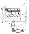
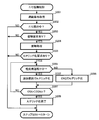
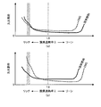
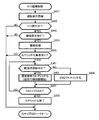
- FIG. 1 is a schematic configuration diagram conceptually showing a configuration of an engine system according to a first embodiment of the present invention. It is a flowchart of F / C control performed in the engine system of FIG. It is a flowchart of the F / C return control performed in the engine system of FIG. It is a timing chart which illustrates one-hour transition of the state of an engine in the execution period of F / C control and F / C return control. It is a figure which shows the characteristic of THC content with respect to oxygen excess rate in CNG and liquid fuel. It is a flowchart of F / C return control concerning a 2nd embodiment of the present invention. It is a figure which shows the characteristic of the misfire ratio of an engine with respect to an oxygen excess rate at the time of using CNG and liquid fuel. It is a flowchart of F / C return control concerning a 3rd embodiment of the present invention.
- FIG. 1 is a schematic configuration diagram conceptually showing the configuration of the engine system 10.
- an engine system 10 is mounted on a vehicle (not shown) and includes an ECU 100, an engine 200, an S / C catalyst 300, and a U / F catalyst 400.
- the ECU 100 is an electronic control unit that includes a CPU (Central Processing Unit), a ROM (Read Only Memory), a RAM (Random Access Memory), and the like, and is configured to be able to control the operation of the engine 200. 1 is an example of an “engine fuel control device”.
- the ECU 100 is configured to execute F / C control and F / C return control, which will be described later, in accordance with a control program stored in the ROM.
- the ECU 100 is an integral electronic control unit configured to function as an example of each of the “first control unit”, “second control unit”, and “first specifying unit” according to the present invention. All the operations related to the means are configured to be executed by the ECU 100.
- the physical, mechanical, and electrical configurations of each of the units according to the present invention are not limited to this.
- each of these units includes a plurality of ECUs, various processing units, various controllers, a microcomputer device, and the like. It may be configured as various computer systems.
- Engine 200 is a four-cylinder engine that is an example of an “internal combustion engine” according to the present invention.
- the outline of the engine 200 will be described.
- the engine 200 has a configuration in which four cylinders 202 are arranged in a cylinder block 201.
- the fuel-air mixture compressed in each cylinder in the compression stroke is ignited and burned by an ignition operation by an ignition device (not shown).
- the force generated during the combustion is converted into a rotational movement of a crankshaft (not shown) connected to the piston via a connecting rod by reciprocating a piston (not shown) in a direction perpendicular to the paper surface. .
- the engine 200 is an in-line four-cylinder engine in which four cylinders 202 are arranged in parallel in a direction perpendicular to the paper surface in FIG. 1, but the configuration of the individual cylinders 202 is equal to each other. Then, only one cylinder 202 will be described.
- the intake air sucked from the outside through the air cleaner 203 is guided to the intake passage 204.
- a throttle valve 205 capable of adjusting the amount of intake air is disposed in the intake passage 204.
- the throttle valve 205 includes a rotary valve that is electrically connected to the ECU 100 and is configured to be rotatable by a driving force supplied from a throttle valve motor (not shown) that is controlled by the ECU 100.
- the rotational position is continuously controlled from the fully closed position where the communication between the upstream portion and the downstream portion of the intake passage 204 at the boundary of 205 is blocked to the fully open position where these are fully communicated. Yes.
- the intake passage 204 is connected to the surge tank 206 on the downstream side of the throttle valve 205 and communicates with the inside thereof.
- the surge tank 206 is connected to a communication pipe (not shown) that is formed in the cylinder block 201 and communicates with an intake port (not shown) corresponding to each cylinder.
- the intake port is configured to communicate with the corresponding cylinder when the intake valve 207 is opened.
- the fuel injection valve of the CNG injector 208 is exposed, and CNG as fuel is injected from the fuel injection valve.
- the CNG injector 208 is an electronically controlled fuel injection device that is electrically connected to the ECU 100 and is an example of the “fuel supply device” according to the present invention.
- the injection amount of CNG in the CNG injector 208 is controlled by the ECU 100. It becomes the composition which is done.
- CNG is an example of “second fuel” and “gas fuel” according to the present invention stored in a gas state in a storage tank (not shown).
- the liquid fuel injector 209 is an electronically controlled fuel injection device that is an example of a “fuel supply device” according to the present invention that can atomize and inject liquid fuel as one fuel of the engine 200 into the intake port.
- the liquid fuel according to the present embodiment is configured as a mixed fuel of gasoline and ethanol.
- the ethanol content ratio in the liquid fuel is variable in the range of 0% (E0 fuel) to 100% (E100 fuel).
- An alcohol concentration sensor capable of detecting the ethanol concentration is attached to the liquid fuel tank that stores the liquid fuel, and the ethanol concentration of the liquid fuel at that time is detected.
- the alcohol concentration sensor is electrically connected to the ECU 100, and the detected ethanol concentration is appropriately referred to by the ECU 100.
- the liquid fuel is an example of “first fuel” and “liquid fuel” according to the present invention.
- the engine 200 has a degree of freedom in the mixing ratio of gasoline and ethanol, and constitutes an example of a so-called FF (Flexible Fuel) engine.
- the engine 200 constitutes an example of a so-called bi-fuel engine that can use CNG and liquid fuel as fuel.
- a mixed fuel of gasoline and ethanol is employed as the “first fuel” and “liquid fuel” according to the present invention, but this is only an example, and the liquid fuel may be gasoline or A single fuel of ethanol may be employed.
- the burned gas that has undergone the combustion stroke in each cylinder passes through the exhaust valve 210 in the exhaust stroke through the exhaust manifold 211.
- the exhaust manifold 211 is connected to an exhaust passage 212 as an example of the “exhaust passage” according to the present invention, and the burned gas flows through the exhaust passage 212 toward the downstream side as exhaust gas.
- an S / C (Start ⁇ Converter) catalyst 300 is installed in the exhaust passage 212.
- the S / C catalyst 300 is a three-way catalyst device in which a noble metal such as platinum or rhodium is supported on a catalyst carrier formed of, for example, a ceramic material or a metal material.
- the S / C catalyst 300 reduces NOx in the exhaust led to the exhaust passage 212 via the exhaust manifold 211 by the reduction action, and oxidizes and burns CO and HC in the exhaust by oxygen obtained by the reduction action.
- This is an example of the “exhaust gas purification apparatus” according to the present invention configured to be capable of purifying NOx, CO, and HC in parallel.
- a U / F (Under-Floor) catalyst 400 is installed downstream of the S / C catalyst 300 in the exhaust passage 212.
- the U / F catalyst 400 is a three-way catalyst device in which a noble metal such as platinum or rhodium is supported on a catalyst carrier formed of, for example, a ceramic material or a metal material.
- the U / F catalyst 400 reduces NOx in the exhaust led to the exhaust passage 212 via the exhaust manifold 211 by the reduction action, and oxidizes and burns CO and HC in the exhaust by oxygen obtained by the reduction action.
- This is another example of the “exhaust gas purification device” according to the present invention configured to be capable of purifying NOx, CO, and HC in parallel.
- the U / F catalyst 400 and the S / C catalyst 300 are both three-way catalyst devices, but their configurations are not necessarily the same. For example, the distribution ratio and amount of the noble metal may be different. .
- the engine system 10 includes an air flow sensor 11, an air-fuel ratio sensor 12, a first O 2 sensor 13, and a second O 2 sensor 14.
- the airflow sensor 11 is a sensor configured to be able to detect an intake air amount Ga that is an amount of intake air in the intake passage 204.
- the air flow sensor 11 is electrically connected to the ECU 100, and the detected intake air amount Ga is appropriately referred to by the ECU 100.
- the air-fuel ratio sensor 12 is a sensor installed in the exhaust passage 212 in the vicinity of the connection portion with the exhaust manifold 211 and configured to detect the exhaust air-fuel ratio AF.
- the air-fuel ratio sensor 12 is electrically connected to the ECU 100, and the detected exhaust air-fuel ratio AF is appropriately referred to by the ECU 100.
- the first O 2 sensor 13 is installed near the outlet of the S / C catalyst 300 in the exhaust passage 212 (on the upstream side of the U / F catalyst 400), and the pre-stage sensor output voltage Vox1 according to the oxygen concentration at the installation site. Is a linear O 2 sensor that outputs.
- the pre-stage sensor output voltage Vox1 becomes higher as the atmosphere around the sensor is a rich atmosphere where oxygen is insufficient, and becomes lower as the atmosphere around the sensor is a lean atmosphere where oxygen is excessive.
- the second O 2 sensor 14 is a linear O 2 sensor that is installed near the outlet of the U / F catalyst 400 in the exhaust passage 212 and outputs a rear sensor output voltage Vox2 corresponding to the oxygen concentration at the installation site.
- the post-stage sensor output voltage Vox2 becomes higher as the atmosphere around the sensor is a rich atmosphere where oxygen is insufficient, and becomes lower as the atmosphere around the sensor is a lean atmosphere where oxygen is excessive.
- the engine system 10 may be equipped with various sensors, but here, the details are omitted for the purpose of preventing the drawings from becoming complicated.
- the engine system 10 includes a vehicle speed sensor that detects the vehicle speed V, a rotation speed sensor that detects the engine rotation speed Ne of the engine 200, an accelerator opening sensor that detects the accelerator opening Ta of the vehicle, and a cooling water temperature Tw of the engine 200.
- a cooling water temperature sensor for detecting the above is provided.
- the ECU 100 acquires the operating conditions of the vehicle and the engine 200 (step S101).
- the operating conditions acquired in step S101 include fuel supply, such as fuel type selection, fuel cut (hereinafter referred to as “F / C” as appropriate), whether or not fuel is required, and the amount and timing of fuel injection. It is the driving
- step S102 determines whether or not F / C is being executed. If F / C is being executed at that time (step S102: YES), ECU 100 returns the process to step S101.
- step S102 when the F / C is not executed (step S102: NO), the ECU 100 determines whether or not the F / C condition is satisfied based on the operation condition acquired in step S101 (step S103). .
- the F / C condition is a condition that is determined in advance as a condition for executing F / C.
- the engine rotational speed Ne is equal to or higher than the reference value
- the vehicle speed V is equal to or higher than the reference value.
- the accelerator opening is defined as an off equivalent value.
- the F / C is qualitatively executed for the purpose of suppressing fuel consumption during coast down running in the middle and high vehicle speed range.
- This F / C condition is an example of the “predetermined condition” according to the present invention, and is not limited to the one exemplified here.
- step S103 NO
- the ECU 100 returns the process to step S101.
- the ECU 100 determines whether or not the vehicle operating conditions (for example, those acquired in step S101) correspond to the liquid fuel supply conditions.
- the vehicle operating conditions for example, those acquired in step S101
- a configuration is employed in which one of liquid fuel and CNG is selectively used as the fuel. Accordingly, the case where the liquid fuel supply condition is satisfied is equivalent to the case where the liquid fuel supply condition is not satisfied.
- CNG has less emission in the cold state than the liquid fuel, and is suitable as a supply fuel in the cold state before the S / C catalyst 300 and the U / F catalyst 400 reach the catalyst activation temperature.
- the engine 200 may be configured such that, for example, CNG is supplied as fuel when the cooling water temperature Tw is lower than the reference value.
- the supply condition of the liquid fuel may be that the coolant temperature Tw is equal to or higher than a reference value.
- the ECU 100 executes liquid fuel injection control.
- the ECU 100 executes CNG injection control.
- the supply conditions of the liquid fuel and CNG are appropriately set according to the specifications, destination, required performance, etc. of the vehicle and the engine system 10, and the embodiment illustrated here is merely an example. .
- the liquid fuel according to this embodiment is a mixed fuel of gasoline and ethanol containing EO fuel of 100% gasoline and E100 fuel of 100% ethanol, and its combustion characteristics and emission amount are greatly increased according to the ethanol concentration. Can change.
- the fuel selection criteria may be appropriately changed according to the ethanol concentration in the liquid fuel at that time.
- CNG is a gaseous fuel and is inferior in volumetric efficiency compared with liquid fuel. In short, mass-based storage is less than liquid fuel. In view of this point, measures from the viewpoint of efficiently using CNG may be taken, such as permitting supply of CNG only under a situation where CNG is significantly superior to liquid fuel.
- step S103 when the F / C condition is satisfied in the F / C non-execution period (step S103: YES), that is, when there is an F / C execution request, the ECU 100 executes F / C (step S104). .
- the ECU 100 selects one of the CNG injector 208 and the liquid fuel injector 209 corresponding to the fuel currently selected as the used fuel so that the fuel supply is stopped. Control.
- the operation according to step S104 is an example of the operation of the “first control unit” according to the present invention.
- the ECU 100 When F / C is executed, the ECU 100 starts calculating the oxygen storage amount OSA (Oxygen Storage Amount) in the S / C catalyst 300 (step S105).
- OSA Oxygen Storage Amount
- the oxygen storage amount OSA is calculated by the following equation (1). It should be noted that once the oxygen storage amount OSA is calculated, it is continuously executed until the end of A / F enrichment in the F / C return control described later.
- OSA ⁇ (0.23 ⁇ mfr ⁇ (AFst ⁇ AF)) ⁇ ⁇ t (1)
- mfr the fuel injection amount per unit time
- AFst the stoichiometry of the fuel used at the time of stopping the injection. It is an air fuel ratio (stoichiometric air fuel ratio). AFst is approximately 14.7 if the fuel used at the time of stopping fuel injection is gasoline (E0 fuel).
- FIG. 3 is a flowchart of the F / C return control.
- the ECU 100 obtains operating conditions in the same manner as in step S101 of F / C control (step S201), and determines whether or not F / C is being executed in the same manner as in step S102 of F / C control. (Step S202). When F / C is not executed (step S202: NO), the ECU 100 returns the process to step S201.
- step S203 the ECU 100 determines whether or not there is a return request from the F / C (step S203).
- the return request means a request to restart the fuel supply.
- step S203: NO the process returns to step S201. In this case, since the above-described step S102 of the F / C control remains “YES”, the F / C is continued.
- the former corresponds to, for example, a case where a drive request is generated by depressing the accelerator pedal, that is, a coast down travel end request.
- the latter corresponds to, for example, a case where the engine 200 is required to start even during coast down traveling because the engine rotational speed Ne has approached a lower limit rotational speed at which the engine can rotate independently.
- whether or not there is a return request may be replaced by whether or not the F / C condition is satisfied, as in step S103 of the F / C control. That is, in this case, it may be determined that there is a return request from the F / C when the F / C is being executed and the F / C condition is not satisfied.
- step S204 When a return request is generated due to a change in the operating conditions of the engine 200 or the vehicle during execution of F / C (step S203: YES), the ECU 100 executes a return process (step S204).
- the return process in step S204 means that F / C is stopped and fuel supply is restarted.
- the fuel at this time may be a fuel conforming to the normal fuel supply control described above.
- the return process is started, the F / C ends.
- the ECU 100 further determines whether or not there is an A / F enrichment request (step S205).
- the A / F enrichment request is a measure to maintain the exhaust air-fuel ratio AF at a rich air-fuel ratio AFr that has been set in the richer side than the stoichiometric air-fuel ratio through experimental adaptation in advance (hereinafter referred to as “A / F” as appropriate). (Abbreviated as “rich”).
- unburned substances such as HC, CO, and H 2 are included in the exhaust of the engine 200 more than under the stoichiometric air-fuel ratio.
- These unburned substances are substances that function as a reducing agent in the catalytic reaction with the S / C catalyst 300, and react with the oxygen stored in the catalyst beyond the proper range by the execution of F / C and burn.
- the decrease in the oxygen storage amount OSA in the S / C catalyst 300 can be promoted.
- step S205 the ECU 100 determines that there is an A / F enrichment request when the oxygen storage amount OSA of the S / C catalyst 300 is equal to or greater than a preset A / F enrichment request reference value. If there is no A / F enrichment request (step S205: NO), that is, if the oxygen storage amount OSA of the S / C catalyst 300 is less than the A / F enrichment request reference value, the process returns to step S201. It is.
- the oxygen storage amount OSA of the S / C catalyst 300 does not deviate from the appropriate range, or the degree of deviation is not large (in other words, In other words, the A / F enrichment request is determined based on the oxygen storage amount OSA so as to cope with the case where the A / F enrichment quickly converges to the appropriate range.
- the return request and the A / F enrichment request may be treated equivalently. That is, the return process may always be executed with A / F enrichment.
- step S205 When there is an A / F enrichment request (step S205: YES), the ECU 100 selects CNG as the fuel to be used, and controls the fuel injection amount of CNG so that the exhaust air-fuel ratio AF becomes AFr. / F enrichment is executed (step S206).
- the ECU 100 starts the calculation in the above-described F / C control, and whether the oxygen storage amount OSA that is integrated at regular intervals is less than the reference value OSAth. It is determined whether or not (step S207).
- the reference value OSAth is the above-described upper limit value that defines the appropriate range of the oxygen storage amount, and is obtained experimentally in advance.
- step S207: NO When the oxygen storage amount OSA is equal to or greater than the reference value (step S207: NO), the ECU 100 continues the A / F enrichment by CNG.
- step S207: YES when the oxygen storage amount OSA decreases to below the reference value (step S207: YES), that is, when the oxygen storage amount OSA of the S / C catalyst 300 converges within the appropriate range, the ECU 100 determines that the A / F rich The process ends (step S208).
- the fuel supply is controlled according to the above-described normal fuel supply control.
- the integrated value of the oxygen storage amount OSA is also reset to the initial value, and the process returns to step S201.
- FIG. 4 is a timing chart illustrating a one-hour transition of the state of the engine 200 during the execution period of the F / C control and the F / C return control.
- time transitions of the F / C flag Fgfc, the oxygen storage amount OSA, the exhaust air / fuel ratio AF, the front sensor output voltage Vox1, and the rear sensor output voltage Vox2 are illustrated in order from the top.
- the F / C flag Fgfc is a flag that is set to an ON value when an F / C condition is satisfied in F / C control and F / C return control, and is set to an OFF value when a return request is generated.
- the F / C flag Fgfc is appropriately set by the ECU 100.
- the oxygen storage amount OSA starts to increase from time T1, and reaches the maximum oxygen storage amount Cmax that is the maximum value of the oxygen storage amount of the S / C catalyst 300 at time T2.
- the oxygen storage amount OSA does not increase any more.
- the exhaust air-fuel ratio AF changes from the stoichiometric air-fuel ratio AFs to the lean side (the value is larger) at time T1.
- the pre-stage sensor output voltage Vox1 rapidly decreases from S1 corresponding to the stoichiometric air-fuel ratio to the F / C time equivalent value L1 at time T1.
- the post-stage sensor output voltage Vox2 rapidly decreases from S2 corresponding to the stoichiometric air-fuel ratio to the F / C time equivalent value L2 at time T1.
- the reason why the values of the front-stage sensor output voltage Vox1 and the rear-stage sensor output voltage Vox2 are different is that the latter is located downstream of the U / F catalyst 400 having a relatively large capacity that functions as a buffer element.
- the exhaust air-fuel ratio (control air-fuel ratio) AF is changed to the above-described rich air-fuel ratio AFr, assuming that there is an A / F enrichment request. Be controlled.
- the oxygen storage amount OSA starts to decrease from the maximum oxygen storage amount Cmax, and at time T4, the oxygen storage amount OSA converges within the appropriate range indicated by hatching in the drawing.
- the return control is terminated, and the exhaust air-fuel ratio AF is again maintained near the stoichiometric air-fuel ratio AFst.
- the purification capacity of emissions (NOx, THC, CO, and H 2 ) in the engine system 10 is that the U / F catalyst 400 is in the lean state. It has been experimentally confirmed that it is extremely high as long as it exists (that is, as long as the oxygen storage amount of the U / F catalyst 400 exceeds the proper range).
- the S / C catalyst 300 and the U / F catalyst 400 can suitably purify the exhaust gas that has more unburned fuel than the stoichiometric air-fuel ratio due to the rich air-fuel ratio. .
- the oxygen storage amount OSA of the S / C catalyst 300 can be quickly converged to an appropriate range by the return process accompanied with the enrichment of the air-fuel ratio.
- FIG. 5 is a graph showing the characteristics of the THC content with respect to the oxygen excess rate in CNG and liquid fuel.
- the CNG has a higher THC content than the liquid fuel, as shown in the figure. That is, when the output characteristics of the engine 200 are made equal, CNG has more THC in the exhaust. Accordingly, the time required for the oxygen storage amount OSA of the S / C catalyst 300 to converge within the appropriate range is shorter when CNG is selected as the fuel than when liquid fuel is selected.
- FIG. 6 is a flowchart of the F / C return control according to the second embodiment. In the figure, the same reference numerals are given to the same portions as those in FIG. 3, and the description thereof will be omitted as appropriate.
- Step S301 is an example of the operation of the second specifying means according to the present invention for specifying the fuel combustion conditions. That is, in the second embodiment, the ECU 100 is configured to operate as an example of the “second specifying unit” according to the present invention.
- the ECU100 calculates the load factor KL of the engine 200 based on the intake air amount Ga detected by the airflow sensor 11 in performing the determination process.
- the load factor KL is defined as the ratio of the intake air amount at that time to the maximum intake air amount of the cylinder 202, and the maximum value is 1.
- the ECU 100 compares the calculated load factor KL with a reference value, and determines that the vehicle is in a light load operation when it is less than the reference value. When the light load operation is not being performed (step S301: NO), the ECU 100 executes A / F enrichment by CNG as in the first embodiment (step S204).
- step S301 when the engine 200 is operating at a light load (step S301: YES), the ECU 100 executes A / F enrichment with liquid fuel without using CNG as the fuel related to A / F enrichment (step S301). S302). Other steps are the same as in the first embodiment.
- Step S302 is the operation of the second control means according to the present invention to “increase the ratio of the first fuel in the supplied fuel when the specified combustion condition corresponds to the predetermined combustion deterioration condition”. In particular, this corresponds to the case where all of the supplied fuel is replaced with the first fuel (liquid fuel).
- FIG. 7 is a diagram showing the characteristics of the misfire ratio of the engine 200 with respect to the oxygen excess rate when CNG and liquid fuel are used.
- FIG. 7 (a) shows the characteristic during high-load operation
- FIG. 7 (b) shows the characteristic during light-load operation.
- shaft means the ratio of the cylinder which misfired among the cylinders which reached the combustion stroke within the predetermined period.
- the definition of the misfire ratio is not limited to this.
- the misfire ratio of CNG when the engine 200 is operating at a high load, the misfire ratio of CNG (see the broken line) and the liquid at the oxygen excess ratio ⁇ indicated by hatching corresponding to the rich air-fuel ratio AFr. It is not significantly different from the fuel misfire rate (see solid line).
- the misfire ratio of CNG when the engine 200 is operating at a light load, the misfire ratio of CNG is significantly larger than that of liquid fuel.
- CNG is a gaseous fuel stored in a gaseous state
- it is already a gaseous state in a state where it is injected from the CNG injector 208.
- CNG is poorly mixed with the intake air, which is also a gas, and the air-fuel mixture in the cylinder tends to be inhomogeneous.
- the low combustibility becomes obvious as an increase in the misfire ratio during the light load operation.
- the ignition temperature of liquid fuel such as gasoline (E0 fuel) is about 210 to 300 ° C.
- the ignition temperature of CNG is as high as about 540 ° C.
- the liquid fuel is injected in the form of a mist from the liquid fuel injector 209, and gasification is promoted when being sucked into the cylinder from the intake port when the intake valve is opened.
- CNG gaseous fuel
- the air-fuel mixture with intake air tends to be homogeneous. Therefore, its combustibility is not easily affected by the load state, and is suitable as an injected fuel during light load operation.
- the second embodiment when the A / F enrichment by CNG is executed for the purpose of suppressing the deterioration of the fuel consumption, the in-cylinder pressure fluctuation, the power performance deterioration or the emission deterioration due to misfire is prevented. can do.
- the fuel is switched to the liquid fuel at the time of light load operation.
- this is only an example.
- a part of CNG is replaced with the liquid fuel in a range in which the malfunction due to the deterioration of combustion is not manifested. May be.
- these supply ratios may be changed stepwise or continuously in accordance with the combustion state of the engine 200 at that time. In this way, it is possible to maintain as much as possible the effect of suppressing fuel consumption deterioration by CNG, which is beneficial in practice.
- ⁇ Third Embodiment> In the F / C return control according to the second embodiment, when the engine 200 is in a light load operation, CNG cannot be used as the fuel related to the return process. The suppression effect cannot be obtained.
- FIG. 8 is a flowchart of the F / C return control according to the third embodiment.
- the same reference numerals are given to the same portions as those in FIG. 6, and the description thereof is omitted as appropriate.
- step S301 when the engine 200 is in a light load operation at the time of starting the return process (step S301: YES), the ECU 100 performs the return control with the liquid fuel as in the second embodiment.
- the fuel is injected not by normal exhaust stroke synchronous injection but by intake stroke synchronous injection (step S401).
- the intake stroke synchronous injection means that at least a part of the fuel is injected when the intake valve is opened, that is, in the intake stroke.
- the liquid fuel injected in the intake stroke is more slowly atomized than when injected when the intake valve is closed (exhaust stroke). For this reason, the uniformity of the air-fuel mixture is inferior.
- Such a decrease in uniformity is unlikely to be an advantage in normal injection control, but can be beneficial in F / C return control. That is, the deterioration of the combustion caused by the deterioration of the uniformity of the air-fuel mixture has the effect of increasing the amount of the reducing agent in the exhaust gas, and thus the A / F enrichment execution period can be shortened.
- a / F rich compared to CNG from the viewpoint of preventing the occurrence of problems caused by various types of combustion deterioration such as misfiring due to deterioration in combustion, reduction in combustion pressure, or reduction in combustion efficiency. Even when a liquid fuel with a small amount of reducing agent under conditions has to be used, it is possible to suppress the deterioration of fuel consumption as much as possible.
- the present invention is not limited to the above-described embodiment, and can be appropriately changed without departing from the gist or concept of the invention that can be read from the claims and the entire specification.
- the control device is also included in the technical scope of the present invention.
- the present invention can be used for controlling the fuel supply state during fuel cut control of an internal combustion engine configured to be capable of using a plurality of fuels.
Landscapes
- Engineering & Computer Science (AREA)
- Chemical & Material Sciences (AREA)
- Combustion & Propulsion (AREA)
- Mechanical Engineering (AREA)
- General Engineering & Computer Science (AREA)
- Oil, Petroleum & Natural Gas (AREA)
- Electrical Control Of Air Or Fuel Supplied To Internal-Combustion Engine (AREA)
- Combined Controls Of Internal Combustion Engines (AREA)
- Output Control And Ontrol Of Special Type Engine (AREA)
Abstract
Description
以下、図面を参照して、本発明の好適な各種実施形態について説明する。
<第1実施形態>
<実施形態の構成>
始めに、図1を参照して、本発明の第1実施形態に係るエンジンシステム10の構成について説明する。ここに、図1は、エンジンシステム10の構成を概念的に表してなる概略構成図である。
<実施形態の動作>
<F/C制御の詳細>
始めに、図2を参照し、ECU100により実行されるF/C制御の詳細について説明する。ここに、図2は、F/C制御のフローチャートである。
上記(1)式において、「0.23」は大気中に含まれる酸素の重量比率であり、mfrは単位時間当たりの燃料噴射量であり、AFstは噴射停止時点において使用されていた燃料のストイキ空燃比(ストイキ空燃比)である。AFstは、燃料噴射停止時点での使用燃料がガソリン(E0燃料)であれば、概ね14.7である。
次に、図3を参照し、F/C復帰制御の詳細について説明する。ここに、図3は、F/C復帰制御のフローチャートである。
<第2実施形態>
F/C復帰制御の態様は、第1実施形態のものに限定されない。ここで、図6を参照し、本発明の第2実施形態に係るF/C復帰制御について説明する。ここに、図6は、第2実施形態に係るF/C復帰制御のフローチャートである。尚、同図において、図3と重複する箇所には同一の符合を付してその説明を適宜省略することとする。
ステップS301は、燃料の燃焼条件を特定する旨の本発明に係る第2特定手段の動作の一例である。即ち、第2実施形態において、ECU100は、本発明に係る「第2特定手段」の一例としても動作する構成となっている。
<第3実施形態>
第2実施形態に係るF/C復帰制御においては、エンジン200が軽負荷運転中である場合には、復帰処理に係る燃料としてCNGを使用することができないため、CNGを使用することによる燃費悪化抑制効果が得られない。
Claims (6)
- 第1燃料と、リッチ空燃比下における排気中の還元剤量が前記第1燃料よりも多い第2燃料とを燃料として供給可能な燃料供給装置を備えた内燃機関と、該内燃機関の排気通路に設けられた排気浄化装置とを備えた車両における、前記内燃機関の燃料制御装置であって、
所定条件下で前記燃料の供給が一時的に停止されるように前記燃料供給装置を制御する第1制御手段と、
前記燃料の供給が一時的に停止された状態から前記燃料の供給を再開させる場合に、前記燃料として前記第2燃料が供給されるように且つ排気空燃比が前記リッチ空燃比となるように前記燃料供給装置を制御する第2制御手段と
を具備することを特徴とする内燃機関の燃料制御装置。 - 前記燃料の供給が一時的に停止される期間における前記排気浄化装置の酸素吸蔵量を特定する第1特定手段を具備し、
前記第2制御手段は、前記特定された酸素吸蔵量が基準値未満となるまで前記排気空燃比を前記リッチ空燃比に維持する
ことを特徴とする請求の範囲第1項に記載の内燃機関の燃料供給制御装置。 - 前記第1燃料は前記第2燃料と較べて燃焼性が高い燃料であり、
前記内燃機関の燃料制御装置は、
前記第2制御手段により前記排気空燃比が前記リッチ空燃比とされる期間における前記燃料の燃焼条件を特定する第2特定手段を更に具備し、
前記第2制御手段は、前記特定された燃焼条件が所定の燃焼悪化条件に該当する場合に、前記供給される燃料における前記第1燃料の比率を増加させる
ことを特徴とする請求の範囲第1項に記載の内燃機関の燃料制御装置。 - 前記第2制御手段は、前記特定された燃焼条件が前記燃焼悪化条件に該当する場合に、前記第2燃料の使用を禁止する
ことを特徴とする請求の範囲第3項に記載の内燃機関の燃料供給制御装置。 - 前記第2制御手段は、前記第1燃料が液体燃料であり且つ前記燃料供給装置が前記第1燃料を前記内燃機関の吸気通路に供給する場合に、前記第1燃料を前記内燃機関の吸気行程に同期して供給させる
ことを特徴とする請求の範囲第3項に記載の内燃機関の燃料供給制御装置。 - 前記第1燃料は液体燃料であり、前記第2燃料はCNGである
ことを特徴とする請求の範囲第1項に記載の内燃機関の燃料供給制御装置。
Priority Applications (5)
| Application Number | Priority Date | Filing Date | Title |
|---|---|---|---|
| CN201080066657.8A CN102906396B (zh) | 2010-06-16 | 2010-06-16 | 内燃机的燃料控制装置 |
| EP10853234.2A EP2584180B1 (en) | 2010-06-16 | 2010-06-16 | Fuel control device for an internal combustion system |
| JP2012520211A JP5418675B2 (ja) | 2010-06-16 | 2010-06-16 | 内燃機関の燃料制御装置 |
| PCT/JP2010/060238 WO2011158353A1 (ja) | 2010-06-16 | 2010-06-16 | 内燃機関の燃料制御装置 |
| US13/640,673 US9239018B2 (en) | 2010-06-16 | 2010-06-16 | Fuel control apparatus for internal combustion engine |
Applications Claiming Priority (1)
| Application Number | Priority Date | Filing Date | Title |
|---|---|---|---|
| PCT/JP2010/060238 WO2011158353A1 (ja) | 2010-06-16 | 2010-06-16 | 内燃機関の燃料制御装置 |
Publications (1)
| Publication Number | Publication Date |
|---|---|
| WO2011158353A1 true WO2011158353A1 (ja) | 2011-12-22 |
Family
ID=45347774
Family Applications (1)
| Application Number | Title | Priority Date | Filing Date |
|---|---|---|---|
| PCT/JP2010/060238 WO2011158353A1 (ja) | 2010-06-16 | 2010-06-16 | 内燃機関の燃料制御装置 |
Country Status (5)
| Country | Link |
|---|---|
| US (1) | US9239018B2 (ja) |
| EP (1) | EP2584180B1 (ja) |
| JP (1) | JP5418675B2 (ja) |
| CN (1) | CN102906396B (ja) |
| WO (1) | WO2011158353A1 (ja) |
Cited By (1)
| Publication number | Priority date | Publication date | Assignee | Title |
|---|---|---|---|---|
| JP2017061872A (ja) * | 2015-09-24 | 2017-03-30 | トヨタ自動車株式会社 | 内燃機関の制御装置 |
Families Citing this family (7)
| Publication number | Priority date | Publication date | Assignee | Title |
|---|---|---|---|---|
| KR20140138319A (ko) | 2012-03-21 | 2014-12-03 | 메이만 리서치, 엘엘씨 | 연료로서 물 기반 혼합물을 사용하는 내연기관 및 그 동작 방법 |
| US8869755B2 (en) | 2012-03-21 | 2014-10-28 | MayMaan Research, LLC | Internal combustion engine using a water-based mixture as fuel and method for operating the same |
| WO2015048187A1 (en) | 2013-09-25 | 2015-04-02 | Yehuda Shmueli | Internal combustion engine using a water-based mixture as fuel and method for operating the same |
| JP2015137579A (ja) * | 2014-01-22 | 2015-07-30 | 株式会社デンソー | 内燃機関の制御装置 |
| CN107002570B (zh) * | 2014-12-02 | 2018-07-24 | 日产自动车株式会社 | 内燃机的控制装置 |
| DE102015204544A1 (de) * | 2015-03-13 | 2016-09-15 | Robert Bosch Gmbh | Verfahren zum Betreiben einer zumindest zeitweise mit Gas betriebenen Brennkraftmaschine |
| JP7354984B2 (ja) * | 2020-10-15 | 2023-10-03 | トヨタ自動車株式会社 | 内燃機関の判定装置 |
Citations (4)
| Publication number | Priority date | Publication date | Assignee | Title |
|---|---|---|---|---|
| JP2005155401A (ja) | 2003-11-25 | 2005-06-16 | Toyota Motor Corp | 内燃機関の空燃比制御装置 |
| JP2005240656A (ja) | 2004-02-26 | 2005-09-08 | Mazda Motor Corp | 水素エンジンの制御装置 |
| JP2006161804A (ja) * | 2004-11-12 | 2006-06-22 | Mazda Motor Corp | パワートレインの制御装置 |
| JP2008291716A (ja) * | 2007-05-23 | 2008-12-04 | Honda Motor Co Ltd | 予混合圧縮着火エンジンの制御装置 |
Family Cites Families (9)
| Publication number | Priority date | Publication date | Assignee | Title |
|---|---|---|---|---|
| JP2001193511A (ja) * | 2000-01-12 | 2001-07-17 | Fuji Heavy Ind Ltd | エンジンの燃料供給制御装置 |
| JP3966014B2 (ja) * | 2002-02-25 | 2007-08-29 | 株式会社デンソー | 内燃機関の排気浄化装置 |
| JP4228900B2 (ja) * | 2003-12-05 | 2009-02-25 | トヨタ自動車株式会社 | 内燃機関の空燃比制御装置 |
| JP2006291716A (ja) * | 2005-04-05 | 2006-10-26 | Honda Motor Co Ltd | 内燃機関の吸排気バルブ |
| JP2008223542A (ja) * | 2007-03-09 | 2008-09-25 | Toyota Motor Corp | 多種燃料内燃機関の燃料制御装置 |
| JP2008274883A (ja) * | 2007-05-01 | 2008-11-13 | Toyota Motor Corp | 内燃機関の制御装置 |
| US8161732B2 (en) * | 2008-03-05 | 2012-04-24 | Ford Global Technologies, Llc | System and method to improve engine emissions for a dual fuel engine |
| EP2546490A4 (en) * | 2010-03-12 | 2017-06-07 | Toyota Jidosha Kabushiki Kaisha | Control device for internal combustion engine |
| WO2013140577A1 (ja) * | 2012-03-22 | 2013-09-26 | トヨタ自動車株式会社 | 内燃機関の制御装置 |
-
2010
- 2010-06-16 US US13/640,673 patent/US9239018B2/en not_active Expired - Fee Related
- 2010-06-16 WO PCT/JP2010/060238 patent/WO2011158353A1/ja active Application Filing
- 2010-06-16 CN CN201080066657.8A patent/CN102906396B/zh not_active Expired - Fee Related
- 2010-06-16 JP JP2012520211A patent/JP5418675B2/ja not_active Expired - Fee Related
- 2010-06-16 EP EP10853234.2A patent/EP2584180B1/en not_active Not-in-force
Patent Citations (4)
| Publication number | Priority date | Publication date | Assignee | Title |
|---|---|---|---|---|
| JP2005155401A (ja) | 2003-11-25 | 2005-06-16 | Toyota Motor Corp | 内燃機関の空燃比制御装置 |
| JP2005240656A (ja) | 2004-02-26 | 2005-09-08 | Mazda Motor Corp | 水素エンジンの制御装置 |
| JP2006161804A (ja) * | 2004-11-12 | 2006-06-22 | Mazda Motor Corp | パワートレインの制御装置 |
| JP2008291716A (ja) * | 2007-05-23 | 2008-12-04 | Honda Motor Co Ltd | 予混合圧縮着火エンジンの制御装置 |
Cited By (2)
| Publication number | Priority date | Publication date | Assignee | Title |
|---|---|---|---|---|
| JP2017061872A (ja) * | 2015-09-24 | 2017-03-30 | トヨタ自動車株式会社 | 内燃機関の制御装置 |
| US10001068B2 (en) | 2015-09-24 | 2018-06-19 | Toyota Jidosha Kabushiki Kaisha | Control apparatus for internal combustion engine |
Also Published As
| Publication number | Publication date |
|---|---|
| CN102906396B (zh) | 2015-06-24 |
| EP2584180A4 (en) | 2014-05-14 |
| EP2584180A1 (en) | 2013-04-24 |
| CN102906396A (zh) | 2013-01-30 |
| JPWO2011158353A1 (ja) | 2013-08-15 |
| US20130030671A1 (en) | 2013-01-31 |
| EP2584180B1 (en) | 2017-10-18 |
| US9239018B2 (en) | 2016-01-19 |
| JP5418675B2 (ja) | 2014-02-19 |
Similar Documents
| Publication | Publication Date | Title |
|---|---|---|
| JP5418675B2 (ja) | 内燃機関の燃料制御装置 | |
| EP1859140B1 (en) | Control apparatus for internal combustion engine | |
| JP4487735B2 (ja) | 内燃機関の制御装置 | |
| US10267255B2 (en) | Control system of internal combustion engine | |
| JP2012057492A (ja) | 触媒暖機制御装置 | |
| JP5110205B2 (ja) | 内燃機関の制御装置 | |
| KR100898884B1 (ko) | 내연 엔진용 제어 장치 | |
| JP2006258009A (ja) | 内燃機関の制御装置 | |
| JP2006161799A (ja) | 内燃機関の制御装置 | |
| JP2009185628A (ja) | 内燃機関の燃料噴射制御システム | |
| JP2010053716A (ja) | 内燃機関の制御装置 | |
| JP2010168949A (ja) | 内燃機関の制御装置、FFV(FlexibleFuelVehicle) | |
| US20130151118A1 (en) | Air-fuel ratio control apparatus, and control method, of hybrid power unit | |
| JP2006258020A (ja) | 内燃機関の制御装置 | |
| JP5067510B2 (ja) | 内燃機関の燃料噴射システム | |
| JP2016156304A (ja) | 内燃機関の燃料切替装置 | |
| JP2007032317A (ja) | 内燃機関の制御装置 | |
| JP2007032318A (ja) | 内燃機関の制御装置 | |
| JP2012255422A (ja) | 内燃機関の制御装置 | |
| JP2013117203A (ja) | 内燃機関の制御装置 | |
| JP4581889B2 (ja) | エンジンの制御装置 | |
| JP2006258011A (ja) | 内燃機関の制御装置 | |
| JP2006258006A (ja) | 内燃機関の制御装置 | |
| JP2016211401A (ja) | 内燃機関の空燃比制御装置 | |
| JP6003770B2 (ja) | 火花点火式エンジンの制御装置 |
Legal Events
| Date | Code | Title | Description |
|---|---|---|---|
| WWE | Wipo information: entry into national phase |
Ref document number: 201080066657.8 Country of ref document: CN |
|
| 121 | Ep: the epo has been informed by wipo that ep was designated in this application |
Ref document number: 10853234 Country of ref document: EP Kind code of ref document: A1 |
|
| WWE | Wipo information: entry into national phase |
Ref document number: 2012520211 Country of ref document: JP |
|
| WWE | Wipo information: entry into national phase |
Ref document number: 13640673 Country of ref document: US |
|
| REEP | Request for entry into the european phase |
Ref document number: 2010853234 Country of ref document: EP |
|
| WWE | Wipo information: entry into national phase |
Ref document number: 2010853234 Country of ref document: EP |
|
| NENP | Non-entry into the national phase |
Ref country code: DE |