WO2011155575A1 - Système de fourniture de services et procédé de fourniture de services - Google Patents
Système de fourniture de services et procédé de fourniture de services Download PDFInfo
- Publication number
- WO2011155575A1 WO2011155575A1 PCT/JP2011/063287 JP2011063287W WO2011155575A1 WO 2011155575 A1 WO2011155575 A1 WO 2011155575A1 JP 2011063287 W JP2011063287 W JP 2011063287W WO 2011155575 A1 WO2011155575 A1 WO 2011155575A1
- Authority
- WO
- WIPO (PCT)
- Prior art keywords
- unit
- robot
- service providing
- work
- robot unit
- Prior art date
Links
- 238000000034 method Methods 0.000 title claims description 33
- 238000012545 processing Methods 0.000 claims abstract description 56
- 239000000463 material Substances 0.000 claims description 124
- 238000005034 decoration Methods 0.000 claims description 62
- 238000003860 storage Methods 0.000 claims description 51
- 239000000853 adhesive Substances 0.000 claims description 21
- 230000001070 adhesive effect Effects 0.000 claims description 21
- 230000007246 mechanism Effects 0.000 claims description 15
- 238000003754 machining Methods 0.000 claims description 14
- 238000005192 partition Methods 0.000 claims description 14
- 238000004891 communication Methods 0.000 claims description 13
- 230000008569 process Effects 0.000 claims description 11
- 235000013305 food Nutrition 0.000 claims description 9
- 235000015243 ice cream Nutrition 0.000 description 34
- 239000006071 cream Substances 0.000 description 33
- 210000000707 wrist Anatomy 0.000 description 14
- 235000015067 sauces Nutrition 0.000 description 13
- 238000010411 cooking Methods 0.000 description 9
- 235000013361 beverage Nutrition 0.000 description 8
- 240000008042 Zea mays Species 0.000 description 7
- 235000005824 Zea mays ssp. parviglumis Nutrition 0.000 description 7
- 235000002017 Zea mays subsp mays Nutrition 0.000 description 7
- 235000005822 corn Nutrition 0.000 description 7
- 101150047356 dec-1 gene Proteins 0.000 description 7
- 235000013353 coffee beverage Nutrition 0.000 description 6
- NJPPVKZQTLUDBO-UHFFFAOYSA-N novaluron Chemical compound C1=C(Cl)C(OC(F)(F)C(OC(F)(F)F)F)=CC=C1NC(=O)NC(=O)C1=C(F)C=CC=C1F NJPPVKZQTLUDBO-UHFFFAOYSA-N 0.000 description 4
- 230000001105 regulatory effect Effects 0.000 description 4
- 244000299461 Theobroma cacao Species 0.000 description 3
- 235000009470 Theobroma cacao Nutrition 0.000 description 3
- 230000009471 action Effects 0.000 description 3
- 235000021185 dessert Nutrition 0.000 description 3
- 238000009434 installation Methods 0.000 description 3
- 229920000515 polycarbonate Polymers 0.000 description 3
- 239000004417 polycarbonate Substances 0.000 description 3
- 239000000843 powder Substances 0.000 description 3
- 239000008256 whipped cream Substances 0.000 description 3
- 235000016623 Fragaria vesca Nutrition 0.000 description 2
- 240000009088 Fragaria x ananassa Species 0.000 description 2
- 235000011363 Fragaria x ananassa Nutrition 0.000 description 2
- 244000290333 Vanilla fragrans Species 0.000 description 2
- 235000009499 Vanilla fragrans Nutrition 0.000 description 2
- 235000012036 Vanilla tahitensis Nutrition 0.000 description 2
- 238000010586 diagram Methods 0.000 description 2
- 235000013399 edible fruits Nutrition 0.000 description 2
- 238000000605 extraction Methods 0.000 description 2
- 208000034423 Delivery Diseases 0.000 description 1
- 230000002159 abnormal effect Effects 0.000 description 1
- 230000005856 abnormality Effects 0.000 description 1
- 238000005452 bending Methods 0.000 description 1
- 230000008901 benefit Effects 0.000 description 1
- 230000008602 contraction Effects 0.000 description 1
- 239000013256 coordination polymer Substances 0.000 description 1
- 238000000151 deposition Methods 0.000 description 1
- 238000001514 detection method Methods 0.000 description 1
- 238000001035 drying Methods 0.000 description 1
- 239000011521 glass Substances 0.000 description 1
- 230000005484 gravity Effects 0.000 description 1
- 210000004247 hand Anatomy 0.000 description 1
- 238000012905 input function Methods 0.000 description 1
- 238000012423 maintenance Methods 0.000 description 1
- 238000012986 modification Methods 0.000 description 1
- 230000004048 modification Effects 0.000 description 1
- 239000002245 particle Substances 0.000 description 1
- 238000003825 pressing Methods 0.000 description 1
- 230000001681 protective effect Effects 0.000 description 1
Images


Classifications
-
- B—PERFORMING OPERATIONS; TRANSPORTING
- B25—HAND TOOLS; PORTABLE POWER-DRIVEN TOOLS; MANIPULATORS
- B25J—MANIPULATORS; CHAMBERS PROVIDED WITH MANIPULATION DEVICES
- B25J9/00—Programme-controlled manipulators
- B25J9/16—Programme controls
- B25J9/1602—Programme controls characterised by the control system, structure, architecture
- B25J9/161—Hardware, e.g. neural networks, fuzzy logic, interfaces, processor
-
- A—HUMAN NECESSITIES
- A23—FOODS OR FOODSTUFFS; TREATMENT THEREOF, NOT COVERED BY OTHER CLASSES
- A23G—COCOA; COCOA PRODUCTS, e.g. CHOCOLATE; SUBSTITUTES FOR COCOA OR COCOA PRODUCTS; CONFECTIONERY; CHEWING GUM; ICE-CREAM; PREPARATION THEREOF
- A23G9/00—Frozen sweets, e.g. ice confectionery, ice-cream; Mixtures therefor
- A23G9/04—Production of frozen sweets, e.g. ice-cream
- A23G9/08—Batch production
-
- A—HUMAN NECESSITIES
- A23—FOODS OR FOODSTUFFS; TREATMENT THEREOF, NOT COVERED BY OTHER CLASSES
- A23G—COCOA; COCOA PRODUCTS, e.g. CHOCOLATE; SUBSTITUTES FOR COCOA OR COCOA PRODUCTS; CONFECTIONERY; CHEWING GUM; ICE-CREAM; PREPARATION THEREOF
- A23G9/00—Frozen sweets, e.g. ice confectionery, ice-cream; Mixtures therefor
- A23G9/04—Production of frozen sweets, e.g. ice-cream
- A23G9/22—Details, component parts or accessories of apparatus insofar as not peculiar to a single one of the preceding groups
- A23G9/28—Details, component parts or accessories of apparatus insofar as not peculiar to a single one of the preceding groups for portioning or dispensing
- A23G9/288—Details, component parts or accessories of apparatus insofar as not peculiar to a single one of the preceding groups for portioning or dispensing for finishing or filling ice-cream cones or other edible containers; Manipulating methods therefor
-
- A—HUMAN NECESSITIES
- A23—FOODS OR FOODSTUFFS; TREATMENT THEREOF, NOT COVERED BY OTHER CLASSES
- A23G—COCOA; COCOA PRODUCTS, e.g. CHOCOLATE; SUBSTITUTES FOR COCOA OR COCOA PRODUCTS; CONFECTIONERY; CHEWING GUM; ICE-CREAM; PREPARATION THEREOF
- A23G9/00—Frozen sweets, e.g. ice confectionery, ice-cream; Mixtures therefor
- A23G9/32—Frozen sweets, e.g. ice confectionery, ice-cream; Mixtures therefor characterised by the composition containing organic or inorganic compounds
- A23G9/322—Products for covering, coating, finishing, decorating
-
- B—PERFORMING OPERATIONS; TRANSPORTING
- B25—HAND TOOLS; PORTABLE POWER-DRIVEN TOOLS; MANIPULATORS
- B25J—MANIPULATORS; CHAMBERS PROVIDED WITH MANIPULATION DEVICES
- B25J9/00—Programme-controlled manipulators
- B25J9/0003—Home robots, i.e. small robots for domestic use
-
- B—PERFORMING OPERATIONS; TRANSPORTING
- B25—HAND TOOLS; PORTABLE POWER-DRIVEN TOOLS; MANIPULATORS
- B25J—MANIPULATORS; CHAMBERS PROVIDED WITH MANIPULATION DEVICES
- B25J9/00—Programme-controlled manipulators
- B25J9/0084—Programme-controlled manipulators comprising a plurality of manipulators
-
- B—PERFORMING OPERATIONS; TRANSPORTING
- B25—HAND TOOLS; PORTABLE POWER-DRIVEN TOOLS; MANIPULATORS
- B25J—MANIPULATORS; CHAMBERS PROVIDED WITH MANIPULATION DEVICES
- B25J9/00—Programme-controlled manipulators
- B25J9/0084—Programme-controlled manipulators comprising a plurality of manipulators
- B25J9/0087—Dual arms
-
- G—PHYSICS
- G07—CHECKING-DEVICES
- G07F—COIN-FREED OR LIKE APPARATUS
- G07F11/00—Coin-freed apparatus for dispensing, or the like, discrete articles
- G07F11/70—Coin-freed apparatus for dispensing, or the like, discrete articles in which the articles are formed in the apparatus from components, blanks, or material constituents
-
- G—PHYSICS
- G07—CHECKING-DEVICES
- G07F—COIN-FREED OR LIKE APPARATUS
- G07F17/00—Coin-freed apparatus for hiring articles; Coin-freed facilities or services
- G07F17/26—Coin-freed apparatus for hiring articles; Coin-freed facilities or services for printing, stamping, franking, typing or teleprinting apparatus
Definitions
- the present invention relates to a service providing system and a service providing method for providing a service using a robot.
- Patent Document 1 proposes an unmanned store having a function of carrying ordered food and drink to a counter table. JP2007-109072
- the present invention has been made in view of such a problem, and provides a service providing system and a service providing method capable of providing a variety of services even if there are no personnel or fewer personnel than usual. It is an object.
- the service providing system includes a robot unit, an interface for receiving input of order input information, the robot unit and the interface, and based on the order input information input by the interface.
- Control means for causing the robot unit to perform work.
- a service providing system 100 includes a robot unit 101, a casing 102, various material supply devices 103A to 103D as one of product processing units, and an article delivery device. (Transportation entrance / exit) 104, input touch panel (interface, settlement means) 105, cash input machine (settlement means) 106, and general computer system (control means) 107.
- the base 1 is fixed to the floor with anchor bolts (not shown), and the body 2 turns with respect to the base 1 via an actuator on the base 1. It is provided freely.
- the body 2 is provided with a first arm 3L and a second arm 3R on the left and right, respectively.
- the second arm 3R is provided with a right shoulder 4R that can turn along a horizontal plane (a plane parallel to the floor).
- the right shoulder 4R is provided with a right upper arm A portion 5R so as to be swingable.
- An upper right arm B portion 6R is provided at the tip of the upper right arm A portion 5R.
- the upper right arm B portion 6R is given a twisting motion to turn.
- a right lower arm portion 7R is swingably provided at the tip of the upper right arm B portion 6R.
- a right wrist A portion 8R is provided at the tip of the right lower arm portion 7R, and a right wrist B portion 9R is provided at the tip.
- the right wrist A part 8R is given a twisting action for turning, and the right wrist B part 9R is given a turning action for performing a bending action.
- a right flange 10R is provided at the tip of the right wrist B portion 9R, and the right hand 11 is attached to the right flange 10R.
- the first arm 3L is symmetrical with the second arm 3R.
- the first arm 3L includes a left shoulder 4L, a left upper arm A portion 5L, a left upper arm B portion 6L, a left lower arm portion 7L, a left wrist A portion 8L, and a left hand. It is composed of a neck B portion 9L and a left flange 10L.
- Each joint (rotation unit, swinging unit, hand) of the robot unit 101 includes an actuator (not shown) having a servo motor, and the rotational position of each movable unit is determined from an encoder built in the actuator.
- the signal is input to the robot controller 107A.
- the torso 2 and the right shoulder 4R, the right shoulder 4R and the upper right arm A part 5R, the upper right arm A part 5R and the upper right arm B part 6R, the upper right arm B part 6R and the right lower arm part 7R, the right lower arm part 7R and right wrist A portion 8R, right wrist A portion 8R and right wrist B portion 9R, right wrist B portion 9R and right flange 10R are rotated relative to each other by driving of an actuator.
- the A portion 8L, the left wrist A portion 8L, the left wrist B portion 9L, the left wrist B portion 9L, and the left flange 10L are rotated relative to each other by driving of the actuator.
- the first arm 3L and the second arm 3R are vertical articulated robots having 7 degrees of freedom, and the robot unit 101 as a whole has 15 degrees of freedom together with the actuator that rotates the base 1 and the body 2. ing.
- the robot unit 101 is a 7-degree-of-freedom vertical articulated robot having redundant degrees of freedom, thereby avoiding interference with surrounding objects and the robot unit 101 itself in a limited space of the housing 102.
- the housing 102 can be configured more compactly, but the degree of freedom of the robot unit 101 is not necessarily limited to that of the present embodiment, and may be one having one or more degrees of freedom.
- the housing 102 is provided so as to surround the robot unit 101 and the space (internal space) in which the robot unit 101 exists and to isolate the robot unit 101 and the material supply devices 103A to 103D.
- the housing 102 is provided with a passageway 102A through which an administrator of the system performs maintenance work inside the housing 102.
- the passage 102A is closed and locked during normal service provision.
- the casing 102 is configured to be foldable after removing the material supply devices 103A to 103D, and is provided with a caster 102B on the lower surface so that it can be transported.
- the material supply devices 103A to 103D are installed in the internal space of the casing 102, respectively.
- the material supply device 103A is a corn dispenser stocked with a plurality of types of soft ice cream cones.
- the material supply apparatus 103B is a soft ice cream server, and a soft ice cream server for general business is applied.
- the material supply device 103C is a topping dispenser in which a plurality of types of toppings (corn flakes, fruits, etc.) are placed.
- the material supply apparatus 103D is a sauce dispenser containing a plurality of types of fruit sauce.
- the article delivery device 104 is a device for delivering the topped soft ice cream created by the robot unit 101 to the customer G.
- the space with the customer G is separated by the polycarbonate plate of the housing 102.
- the robot unit 101 and the customer G are not in direct contact with each other. The details of the configuration of the article delivery device 104 will be described later with reference to FIGS.
- the input touch panel 105 has a display monitor, and is configured to be able to input information by touching the display screen.
- the display monitor displays an order input screen for accepting the input of product specifications.
- the order input screen is configured so that a soft cream container (amount), cream type, topping material, and source type can be selected and input from the input touch panel 105.
- the soft cream container (amount), the type of cream, the topping material, and the type of sauce correspond to the setting information (information that can be specified by the customer G) for one product. Information is organized.
- the overall computer system 107 is composed of a robot controller 107A that controls the operation of the robot unit 101 and an external computer 107B, each having a computing device, an input device, and a display device. Etc. are connected so that delivery etc. are possible.
- the input touch panel 105 is connected to the external computer 107B.
- the external computer 107B has a work storage unit 108A, a settlement processing unit (settlement means) 108B, a processing selection unit 108C, a processing work command unit 108D, and a product carry-out command unit 108E as functions.
- the work storage unit 108A is a storage device that stores at least one machining operation, and the machining operation is stored for each type of machining operation as teaching data describing the operation mode of the robot unit 101.
- the payment processing unit 108B When the payment processing unit 108B receives a predetermined amount of money into the cash input device 106 or an input of predetermined payment information into the input touch panel 105, the payment processing unit 108B executes a payment process that permits work on the robot unit 101. Yes.
- the processing selection unit 108C selects a processing operation that matches the order input information from the processing operations stored in the operation storage unit 108A based on the order input information input to the input touch panel 105.
- the machining operation command unit 108D generates a command to the robot controller 107A according to the machining operation selected by the machining selection unit 108C.
- the robot controller 107A operates the robot unit 101 in accordance with the command, and cooks the materials of the material supply devices 103A to 103D as will be described later.
- the product carry-out commanding unit 108E determines that the processing by the processing work commanding unit 108D has been completed and the processing operation of the robot unit 101 has been executed, the product delivery device 104 sends the cooked product (soft cream here) to the product delivery device 104. To the customer G.
- the service providing system 100 is configured as described above and operates as follows. Until the customer G deposits into the cash dispenser 106, the robot unit 101 does not start the work of creating the item and is on standby. After the cash dispenser 106 detects the deposit, the input touch panel 105 displays an order input screen (a container, soft cream, topping, sauce type, etc.).
- an order input screen a container, soft cream, topping, sauce type, etc.
- the robot unit 101 starts the cooking process to extract the material and make the soft ice cream.
- the procedure will be described by taking as an example a case where dessert corn is selected as the container, vanilla is selected as the type of soft cream, corn flakes as the topping, and strawberry as the sauce.
- the external computer 107B sends a command to the robot controller 107A according to the order input information set by the input touch panel 105, and the robot controller 107A gives the robot unit 101 an operation start command.
- the robot unit 101 detects a bottom surface of a dessert cone (hereinafter referred to as a cone) stacked on the material supply device 103A by a sensor (not shown) provided in the left and right hands 11 and 12, and holds a certain amount of the cone from the bottom surface of the cone.
- a gripping operation is performed by recognizing the position.
- the cone After the cone has been grasped, the cone is pulled up, and the left and right second arms 3R and first arm 3L of the robot unit 101 are moved so that the grasped cone does not interfere with the casing 102 and the material supply devices 103A to 103D.
- drum 2 is turned and it faces to the material supply apparatus 103B.
- the hand that does not hold the cone for example, the left hand 12 for holding the cone, and the lever operation
- An operation of engaging (inserting) a lever (hereinafter referred to as a soft cream lever) provided in the soft cream server is performed on a ring-shaped engagement portion (not shown) provided in the right hand 11).
- the robot unit 101 moves the soft ice cream lever down to deliver the soft ice cream, and the left hand 12 moves the soft ice cream.
- the right hand 11 raises the soft ice cream lever to stop the soft ice cream from appearing.
- the soft ice cream lever is raised to a position where soft ice cream does not come out, the ring-shaped engaging portion of the right hand 11 is removed from the soft ice cream lever, and the body portion 2 is turned to face the material supply device 103C.
- the robot controller 107A moves the soft cream gripped by the left hand 12 to the topping dispenser of the topping dispenser, and the right hand 11 dials the topping dispenser.
- a certain amount of the contents of the topping dispenser here, cornflakes
- the cornflakes are sprinkled on the soft ice cream.
- the right hand 11 When a certain amount of topping is discharged, the right hand 11 is removed from the topping dispenser, and both arms are operated so that the soft cream gripped by the right hand 11 and the left hand 12 does not interfere with the housing 102 and the materials 103A to 103D. It faces in the direction of the material supply device 103D.
- the robot controller 107A moves the soft cream gripped by the left hand 12 to the source extraction position of the source dispenser, and the right hand 11 Then, the source dispenser 103D is gripped, the source dispenser 103D is moved to the source extraction position, and a certain amount of strawberry-flavored sauce is hung on the soft cream gripped by the left hand 12.
- the source dispenser 103D gripped by the right hand 11 is returned to the original position.
- the robot controller 107A places a soft cream gripped by the left hand 12 in a later-described cradle 83 (see FIG. 5) provided in the article delivery device 104. ), And the right hand 11 performs the operation of providing the soft serve to the customer G. Details of the operations of the right hand 11 and the article delivery device 104 will be described later with reference to FIGS.
- the right hand 11 is moved to the housing 102.
- the right arm is moved to a standby posture so as not to interfere with the cash and the like, and then waits for depositing into the cash thrower 106.
- the customer G deposits the money into the cash dispenser 106 and displays it on the input touch panel 105 without any other person (for example, a store employee).
- a combination of your choice in this example, dessert corn as a container, vanilla as a soft ice cream type, corn flakes as a topping, strawberry as a sauce
- you can purchase a combination of your choice (in this example, dessert corn as a container, vanilla as a soft ice cream type, corn flakes as a topping, strawberry as a sauce)
- the operation mode (teaching data) of the robot unit 101 constituting the processing operation is set to imitate the operation of a more skilled soft ice cream cook, the cooking process closer to the skilled soft ice cream cook is repeated. Can be reproduced with high accuracy, and the value of the products provided can be improved.
- an air chuck or a servo gripper can be considered, but it is not limited.
- the ring is used as the soft cream lever operation with the right hand 11 and the operation method of the delivery unit, an air chuck or a servo gripper may be used as another method.
- a method for grasping the source dispenser 103D and a method for extracting a certain amount of sauce are not specified, the method is not limited as long as a certain amount of the sauce can be extracted.
- corn, soft cream, topping, and sauce are combined in this order.
- the order of topping and sauce may be reversed, and a plurality of types of topping and sauce may be combined.
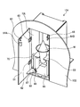
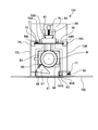
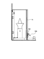
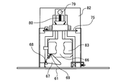
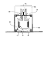
- the article delivery device 104 includes a customer side door (outside partition member) 61, a spring hinge 62, a customer side sensor plate 63, a customer side key (opening / closing adjusting means) 64A, and a customer side key.
- the front wall portion of the housing 102 is a partition member, and the customer side door 61, the top plate 72, the side plate right 73R, the side plate left 73L, and the robot side door 75 are provided in openings provided in the housing 102.
- a communication member partitioned by a column right 74R, a column left 74L, and a pedestal 82 is formed, and the inside (robot side) and the outside of the housing 102 can communicate with each other through the communication member.
- a pair of guides 81 extending inward and outward of the housing 102 are installed on the pedestal 82 so as to face each other, and a delivery table 66 and a lever 79 are slidably disposed along the guides 81. It is installed.
- a delivery table spring 80 as a buffer member is provided in the substantially same direction as the extending direction of the guide 81.
- a stand 83 is provided at the tip of the delivery stand spring 80. That is, contact force is transmitted between the delivery table 66 and the lever 79 via the delivery table spring 80.
- the delivery table 66 is provided with a platform 83 having a shape suitable for placing the soft cream W.
- the platform 83 has a soft cream sensor 70 that detects whether or not the soft cream W is placed. It is attached.
- the robot-side door 75 is slidable in the vertical direction along the grooves 84R and 84L provided in the column right 74R and the column left 74L, respectively. That is, in the present embodiment, the first opening / closing mechanism is formed by the grooves 84R and 84L.
- the customer-side door 61 is attached to the left side plate 73L by spring hinges 62, 62 attached to the upper and lower sides, respectively, and can be opened and closed using the spring hinges 62, 62 as hinges. . That is, in this embodiment, the customer side door 61 and the spring hinges 62 and 62 form part of the opening / closing adjustment means. Further, the spring hinges 62, 62 are urged by a built-in spring so that the customer-side door 61 is always closed.
- a customer side key 64A is attached to the customer side door 61, and a customer side key 64B is provided on the left side plate 73L.
- the customer side keys 64A and 64B are engaged with each other to prohibit the opening and closing operation of the customer side door 61.
- a customer side sensor plate 63 is attached to the customer side door 61, and a customer side sensor 65 is provided on the left side plate 73L.
- the customer side sensor 65 is a sensor that detects whether or not the customer side sensor plate 63 is in contact. That is, the customer side sensor 65 detects whether or not the customer side door 61 is in a fully closed state and sends the detection result to the external controller 107B. It comes to input.
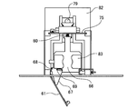
- the customer-side keys 64A and 64B are engaged with each other to prohibit the opening and closing operation of the customer-side door 61. Further, as shown in FIG. 8, the customer side key 64B is urged by the customer side key spring 71 in the direction in which the customer side keys 64A and 64B are engaged with each other, and the base end portion 85 of the customer side key 64B is encased. By pushing from the inside of the body 102, the engagement of the customer side keys 64A and 64B is released.
- a robot side key 76B is attached to the robot side door 75.
- the robot side key 76A extends upward from the pedestal 82, and the robot side key 75A engages with the engaging portion on the upper end side of the robot side key 76A, so that the robot side door 75 slides. Is regulated (prohibited). That is, in this embodiment, the robot side keys 76A and 76B form part of the opening / closing adjustment means.
- the customer side door 61 is closed.
- the robot unit 101 is operated while holding the robot side key 76B with the right hand 11 or the left hand 12, and the robot side key 76B is continuously pulled up, the robot side door 75 is fixed because the robot side key 76B is fixed.
- Moves upward the partition between the inside of the communicating member and the inside of the housing 102 is removed, and the inside of the communicating member communicates with the inside of the housing 102.
- the customer side door 61 is confirmed to be closed, the customer G or the like is prevented from being improperly accessed from the customer side door 61 to the robot side.
- the right hand 11 and the left hand 12 holding the soft cream W are intruded into the communication member, the soft cream W is placed on the placing table 83, and the gripping of the soft cream W by the right hand 11 and the left hand 12 is released.
- the soft ice cream sensor 70 confirms that the soft ice cream W is set on the cradle 83, and as shown in FIG. 11, the robot unit 101 uses the gravity to hold the robot side key 76B. Close the side door 75.
- the customer side door 61 is closed by the robot side sensor 78, and the robot unit 101 is operated as shown in FIGS.
- the customer side keys 64A and 64B are disengaged by pressing 85, and the lever 79 is pushed to the outside of the housing 102 (on the customer side door 61 side) by the right hand 11.
- the customer G When the customer G receives the soft ice cream W, as shown in FIG. 14, it is input to the external controller 107 ⁇ / b> B that the customer G is receiving the soft ice cream W from the table 83 by the input from the soft ice cream sensor 70.
- the robot unit 101 delivers the soft ice cream W in a state where the customer-side door 61 is not closed because the customer-side door 61 is open and the customer-side door 61 is not closed. Therefore, even if the lever 79 is pulled, the cam 67 and the delivery table 66 and the customer side door 61 are configured to operate independently, so that the customer side door 61 can be kept open.
- the influence on the customer G side is minimized, and the customer side door 61, the delivery table 66 and the robot unit 101 are not damaged. Furthermore, since the customer side door 61 is configured to be closed by a spring hinge 62, the normal system is restored if the cause of the customer side door 61 not being closed is resolved.
- the robot unit 101 pushes the lever 79 for the delivery operation of the soft cream W in a state where the customer door 61 is not opened for some reason, such as the customer door 61 being pressed from the outside. Even in such a case, the pushing operation of the lever 79 is absorbed by the contraction of the delivery stand spring 80. Therefore, the influence on the customer G side is minimized, and damage to the customer side door 61, the delivery table 66, the robot unit 101, and the like is prevented or reduced.
- an item here, soft ice cream W
- an unauthorized access to the inside of the casing 102 through the article delivery device 104 is made. Since it is possible to see the process in which the product is delivered by the operation of the robot unit 101 while preventing intrusion, the product is delivered without giving an inorganic impression to the customer G as in a vending machine, for example. be able to. Further, there is an advantage that it is not necessary to provide power for conveyance such as a conveyor for the article feeding device 104.
- a decorative material such as glass particles is applied to a hand mirror (product, base material) as a product along a placement pattern ordered (selected) as a product, and decorated to customers.
- the robot decoration system to be provided will be described.
- description is abbreviate
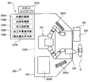
- the service providing system 200 includes a robot unit 201, a casing 102, a work stage 203, an article feeding device 204, an input touch panel (interface, settlement means) 205, a cash dispenser ( Settlement means) 106, general computer system 207, decoration material storage area (small member storage part) 209, work decoration material storage place 210, hand mirror storage shelf (base material storage part) 211, adhesive gun storage place (adhesive supply tool storage) Part) 212.
- a robot unit 201 a casing 102, a work stage 203, an article feeding device 204, an input touch panel (interface, settlement means) 205, a cash dispenser ( Settlement means) 106, general computer system 207, decoration material storage area (small member storage part) 209, work decoration material storage place 210, hand mirror storage shelf (base material storage part) 211, adhesive gun storage place (adhesive supply tool storage) Part) 212.
- the robot unit 201 is configured in substantially the same manner as the robot unit 101 of the first embodiment. The detailed configuration will be described again.
- the base 51 is fixed to the installation surface by an anchor bolt (not shown), and an actuator 52A is mounted on the base 51.
- the body 52 is provided so as to be pivotable about the rotation axis Ab of the actuator 52A with respect to the base 51.
- the body 52 is provided with a first arm 53L and a second arm 53R on the left and right, respectively. ing.
- the rotation axis Ab of the actuator 52A and the rotation axis A1 of the first actuator of the first arm 53L and the second arm 53R are displaced with respect to the base 51 so as to be shifted by a length D1 in a direction horizontal to the installation surface.
- the shape of the body portion 52 is set so that the body portion 52 protrudes horizontally forward.
- the first arm 53L has a first structure material 41, a second structure material 42, a third structure material 43, a fourth structure material 44, and a fifth structure in order from the body 52 side to the tip.
- the material 45, the sixth structural material 46, and the flange 47 are connected via actuators (rotary joints) that are driven to rotate.
- drum 52 and the 1st structural material 41 are connected via the 1st actuator (1st joint) 41A, and the 1st structural material 41 rotates by the drive of the 1st actuator 41A.
- the first structural material 41 and the second structural material 42 are connected via a second actuator (second joint) 42A, and the second structural material 42 turns by driving the second actuator 42A. ing.
- the second structural member 42 and the third structural member 43 are connected via a third actuator (third joint) 43A, and the third structural member 43 is rotated by driving the third actuator 43A. ing.
- the third structural member 43 and the fourth structural member 44 are connected via a fourth actuator (fourth joint) 44A, and the fourth structural member 44 turns by driving the fourth actuator 44A. ing.
- the fourth structural member 44 and the fifth structural member 45 are connected via a fifth actuator (fifth joint) 45A, and the fifth structural member 45 is rotated by driving the fifth actuator 45A. ing.
- the fifth structural member 45 and the sixth structural member 46 are connected via a sixth actuator (sixth joint) 46A, and the sixth structural member 46 turns by driving the sixth actuator 46A. ing.
- the sixth structural member 46 and the flange 47 are connected via a seventh actuator (seventh joint) 47A, and the flange 47 is rotated by driving the seventh actuator 47A.
- the flange 47 is provided with a left hand 48 capable of expanding and reducing the distance between the pair of finger portions by driving an actuator (not shown).
- the shape of the third structural member 43 is set so that the rotation axis A3 of the third actuator 43A and the rotation axis A4 of the fourth actuator 44A are shifted by a length D2 when viewed from above.
- the shape of the fourth structural member 44 is set so that the rotation axis A4 of the fourth actuator 44A and the rotation axis A5 of the fifth actuator 45A are shifted by a length D3 when viewed from above.
- the rotation axis A3 of the third actuator 43A and the rotation axis A5 of the fifth actuator 45A are length (
- the shape of each structural material is set so as to be shifted by D2 + D3), and interference between the second to fifth structural materials 42 to 45 when the fourth actuator 44A is bent is suppressed, and the base 51 and the body An operation area of the robot unit 201 in the vicinity of the unit 52 is secured.
- the second arm 53R is configured in the same manner as the first arm 53L described above, and the installation direction to the trunk portion 52 is shifted by 180 degrees.
- On the second arm 53R there is a right hand 49 having a pair of finger members that expand and contract in the same manner as the left hand 48 and a suction device at the tip so that the decoration material can be adsorbed one by one from the decoration material cassette described later. It is attached.
- the work stage 203 has a substantially horizontal work surface and a position regulating jig 203A for alignment.
- the hand mirror V is stored in the central computer system 207 in advance by bringing the hand mirror V into contact with the position regulating jig 203A. It is positioned and placed at the position.
- the article delivery device 204 is a device for passing the hand mirror V decorated by the robot unit 201 to the customer G, and the space with the customer G is separated by a polycarbonate plate. Note that the robot unit 201 is always locked and a delivery operation is performed by the robot unit 201 when the product is delivered, so that the robot unit 201 and the customer G cannot directly contact each other.
- the input touch panel 205 has a display monitor, and is connected to the general computer system 207 so as to be able to communicate information.
- the customer G can input information to the general computer system 207 side by touching the display monitor.
- the input touch panel 205 is provided with a data reading device (input port) that can read the arrangement pattern data of the decoration material, and can accept the arrangement pattern data prepared by the customer G.
- the reading device may be the simplest device for reading electronic data from a recording medium, and may further have a picture input function for converting information on the picture drawn by the customer G on the spot.
- the display monitor of the input touch panel 205 displays an order input screen for accepting product specification input. More specifically, a hand mirror selection screen for displaying a plurality of types of hand mirrors V and selecting a desired type is displayed on the order input screen.
- a custom / original selection screen for selecting a custom arrangement picture stored in advance in the overall computer system 207 or inputting an original arrangement picture of the customer G from the data reader is displayed.
- the arrangement picture creation unit 208F of the overall computer system 207 creates the arrangement coordinate data of the decoration material based on the inputted arrangement picture data. At this time, the arrangement picture creation unit 208F determines whether or not the processing operation by the robot unit 201 is possible, such as a mismatch between the type of the selected hand mirror V and the input arrangement picture data, and the processing operation is performed. If it is determined that the arrangement pattern data is not possible, the display monitor displays that fact and the previous custom / original selection screen is displayed again.
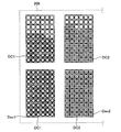
- the decoration material storage area 209 is provided in the vicinity of the second arm 53R of the robot unit 201. As shown in FIG. 21, the decoration material storage area 209 has a plurality of small storage rooms arranged vertically and horizontally. A plurality of material cassettes DC1 and DC2 are positioned and placed. One decoration material Dec1, Dec2 is accommodated in each of the storage compartments of the decoration material cassettes DC1, DC2. Note that information about the sizes and positions of the storage compartments of the decorative material cassettes DC1 and DC2 or the sizes of various decorative materials is stored in the overall computer system 207 in advance.
- the decorative material cassette DC1 stores the same type of decorative material Dec1
- the decorative material storage area 209 stores two decorative material cassettes DC1 and DC2 each storing the same type of decorative material.
- FIG. 21 only two types of decoration material and decoration material cassettes DC1 and DC2 are illustrated, but the type and number of decoration materials can be set as appropriate according to the type of rhinestone or the like used as the decoration material. is there.
- the work decoration material storage 210 is provided at a position closer to the work stage 203 than the decoration material storage area 209, and is formed so that the two decoration material cassettes DC1 and DC2 can be positioned and placed.
- the hand mirror storage shelf 211 stores a plurality of types of hand mirrors V as products, and the types and storage positions of the hand mirrors V are stored in advance in the overall computer system 207.
- An adhesive gun (not shown) for supplying an adhesive is placed in the adhesive gun storage 212.
- the adhesive gun can be held by the left hand 48, and the start / stop of the supply of the adhesive from the tip can be operated by the operation of the left hand 48.
- a control system including a robot controller is configured by a general computer system 207 which is an integrated arithmetic device.
- the control device may be configured by a separate arithmetic device group that shares functions as in the first embodiment.
- the overall computer system 207 has a work storage unit 208A, a settlement processing unit (settlement means) 208B, a processing selection unit 208C, a robot control unit 208D, a product carry-out command unit 208E, and an arrangement picture creation unit 208F as functions.
- the work storage unit 208A stores the work procedure of the processing operation for the hand mirror V for each selected hand mirror V and the corresponding arrangement pattern.
- the machining operation is stored as teaching data describing the operation mode of the robot unit 201.
- teaching data the type of the decoration material used for the arrangement pattern and the arrangement position (arrangement coordinates) of the various decoration materials with respect to the hand mirror V are stored. Contains information.
- the payment processing unit 208B executes a payment process for allowing the robot unit 201 to work. Yes.
- the processing selection unit 208C based on the order input information input to the input touch panel 205, changes the processing work that matches the order input information from the processing work stored in the work storage unit 208A. Select.
- the robot control unit 208D generates an operation command for each actuator of the robot unit 201 according to the machining operation selected by the machining selection unit 208C, and operates the robot unit 201.
- the product carry-out command unit 208E determines that the processing operation by the robot unit 201 has been completed, the product (in this case, the hand mirror V) is placed on the article delivery device 204.
- the arrangement picture creating unit 208F creates the arrangement coordinate data of the decoration material based on the arrangement picture data input from the data reading device as described above.
- the overall computer system 207 stores arrangement interval information for all types of decoration materials in advance, and the arrangement picture creation unit 208F replaces the arrangement picture data with the arrangement coordinates of each type of decoration material, thereby arranging the arrangement coordinates of the decoration material. Create data.
- the service providing system 200 is configured as described above, and operates as follows.
- the robot unit 201 is on standby until the customer G deposits money into the cash dispenser 106.
- the input touch panel 205 displays an order input screen (hand mirror selection screen, custom / original selection screen, arrangement picture selection screen, etc.).
- the processing selection unit 208C selects the processing operation, and the corresponding operation procedure is selected from the plurality of processing operation procedures stored in the operation storage unit 208A.
- the work procedure will be described by taking as an example a case where an arrangement pattern as shown in FIG. 22 is selected.
- the first arm 53L is operated and the selected type of hand mirror V is gripped by the left hand 48 and taken out from the hand mirror storage shelf 211, and the position regulating jig 203A of the work stage 203 is placed.
- the hand mirror V held in contact with is placed on the work stage 203 with the position of the hand mirror V being positioned.
- the first arm 53L moves to the adhesive gun storage 212, holds the adhesive gun with the left hand 48, and stops at a standby position near the work stage 203.
- the second arm 53R operates in parallel with the operation of the first arm 53L, and based on the selected arrangement picture data, a decoration material cassette of the type (initially Dec1) used for the latest work from the decoration material storage area 209.
- the DC1 is gripped by the finger member of the right hand 49 and positioned and placed on the work decoration storage area 210. At this time, two decoration material cassettes DC1 of the same type are transferred from the decoration material storage area 209 to the work decoration material storage area 210.
- the first arm 53L attaches the adhesive from the adhesive gun to the predetermined position of the hand mirror V based on the arrangement position information of the decoration material with respect to the hand mirror V, and returns to the standby position again.
- the standby position is set in advance to a position where the second arm 53R does not interfere with the first arm 53L and the second arm 53R when the decorative material is placed.
- the suction device of the right hand 49 of the second arm 53R sucks one decoration material Dec1 from the storage compartment of the decoration material cassette DC1 placed in the work decoration material storage 210, and attaches it to the hand mirror V with an adhesive gun.
- the decoration material Dec1 is placed at the position of the adhesive.
- the overall computer system 207 records the use order and position of each storage compartment of each decoration material cassette DC1, DC2 and the number of past use of the decoration material.
- the decoration material is taken out in order.
- the work of pasting on the hand mirror V is executed.
- the adhesive application operation by the first arm 53L and the decoration material placement operation by the second arm 53R are alternately and repeatedly executed by the number of the decoration material Dec1 included in the placement picture.
- the second arm 53R transfers the decoration material cassette DC1 of the work decoration material storage area 210 to the decoration material storage area 209, and from the decoration material storage area 209 to the next work.
- the decoration material cassette DC2 to be used is taken out and transferred to the work decoration material storage 210.
- the material placement operation is repeatedly executed by the number of decoration materials Dec2 included in the placement picture.
- the same operation is repeated for the decoration material Dec3, and the arrangement operation of the decoration material is completed as shown in FIG.
- the first arm 53L is operated and the hand mirror V on which the decoration material is placed is gripped by the left hand 48 and transferred to the article feeding device 204, where a predetermined time (drying of the adhesive is performed).
- a predetermined time drying of the adhesive is performed.
- the first arm 53L is operated and the left hand 48 opens the article delivery device 204, and the hand mirror V is delivered to the customer G as a product.
- the present embodiment is configured in the same way as the first embodiment except that the content configuration of the material supply apparatus and the operation mode of the robot are different from those of the first embodiment described above. Are omitted and the same reference numerals are used.
- the material supply device 303A is a cup dispenser in which beverage cups C having a plurality of sizes are stocked.
- the material supply device 303B is a coffee maker for general business use.
- the material supply device 303C is a topping dispenser containing a plurality of types of topping products (cocoa powder, whipped cream, etc.).
- the overall computer system 307 is configured in the same manner as that of the first embodiment.
- the work storage unit 308A stores decorative picture data of a plurality of types of topping products corresponding to the type of the selected cup C in the robot unit. 101 is stored as operation information.
- the order input screen displayed on the input touch panel 305 includes a size selection screen that accepts selection of the size (amount) of the cup C, and a coffee beverage such as cream or cocoa powder as illustrated in FIG.
- a decoration selection screen for displaying a plurality of types of arrangement forms (placement patterns) according to the arrangement of the topping products and selecting a desired arrangement form is displayed.
- the service providing system 300 is configured as described above.
- the robot unit 101 operates and the right hand 11 of the second arm 3R moves from the material supply device 303A.
- the beverage cup C having a size corresponding to the selected content is taken out, and the coffee beverage corresponding to the selected size is stored in the beverage cup C by operating the material supply device 303B.
- the first arm 3L operates in parallel with the operation of the second arm 3R, and the topping product dispenser suitable for the selection content of the customer G is gripped by the left hand 12 from the material supply device 303C. Thereafter, the second arm 3R takes a preset posture while holding the beverage cup C, positions the beverage cup C, and the serving mode selected by the customer G by the first arm 3L holding the topping product dispenser. Then, a serving operation using a topping product is performed on the beverage cup C.
- the whipped cream is uniformly poured on the coffee beverage in the beverage cup C by the operation of the left hand 12, and then the topping product dispenser is changed from the material supply device 303C by the operation of the left hand 12. Then, an operation of arranging the cocoa powder CP along the pattern as shown in FIG. 24 from above the whipped cream WC is performed.
- the operation of a skilled craftsman is stored in advance, thereby stably processing coffee products that require high-precision work. Can be reproduced, and the value of the product to be provided can be improved.
- an article such as a mobile phone or a T-shirt owned by a customer is supplied to the inside of the housing through the carry-in / out entrance, and the order input information is input through the interface, so that the supplied article can be installed and processed with ornaments.
- You may comprise so that it may give.
- you may comprise so that things other than the goods illustrated in embodiment, such as cooking and provision of a cocktail drink, may be processed (cooked) and provided.
- the settlement means may be configured to select not only a cash input device but also various settlement methods.
- the robot controller and the external computer are separately configured to configure a general computer system as control means.
- the control means may be configured as a functional element of one computer.
- a plurality of computers may be linked to constitute a control means.
Abstract
Priority Applications (4)
| Application Number | Priority Date | Filing Date | Title |
|---|---|---|---|
| CN2011800281974A CN102934148A (zh) | 2010-06-11 | 2011-06-09 | 服务提供系统和服务提供方法 |
| BR112012030688A BR112012030688A2 (pt) | 2010-06-11 | 2011-06-09 | sistema de fornecimento de serviço, e, método de fornecimento de serviço |
| EP11792532.1A EP2581885A1 (fr) | 2010-06-11 | 2011-06-09 | Système de fourniture de services et procédé de fourniture de services |
| US13/710,496 US8948912B2 (en) | 2010-06-11 | 2012-12-11 | Service providing system and service providing method |
Applications Claiming Priority (6)
| Application Number | Priority Date | Filing Date | Title |
|---|---|---|---|
| JP2010-133981 | 2010-06-11 | ||
| JP2010133981 | 2010-06-11 | ||
| JP2010166423A JP5402867B2 (ja) | 2010-07-23 | 2010-07-23 | 物品送入装置及びサービス提供システム並びにロボット |
| JP2010-166423 | 2010-07-23 | ||
| JP2010-261275 | 2010-11-24 | ||
| JP2010261275A JP5516366B2 (ja) | 2010-06-11 | 2010-11-24 | サービス提供システム及びサービス提供方法 |
Related Child Applications (1)
| Application Number | Title | Priority Date | Filing Date |
|---|---|---|---|
| US13/710,496 Continuation US8948912B2 (en) | 2010-06-11 | 2012-12-11 | Service providing system and service providing method |
Publications (1)
| Publication Number | Publication Date |
|---|---|
| WO2011155575A1 true WO2011155575A1 (fr) | 2011-12-15 |
Family
ID=47647718
Family Applications (1)
| Application Number | Title | Priority Date | Filing Date |
|---|---|---|---|
| PCT/JP2011/063287 WO2011155575A1 (fr) | 2010-06-11 | 2011-06-09 | Système de fourniture de services et procédé de fourniture de services |
Country Status (5)
| Country | Link |
|---|---|
| US (1) | US8948912B2 (fr) |
| EP (1) | EP2581885A1 (fr) |
| CN (1) | CN102934148A (fr) |
| BR (1) | BR112012030688A2 (fr) |
| WO (1) | WO2011155575A1 (fr) |
Cited By (7)
| Publication number | Priority date | Publication date | Assignee | Title |
|---|---|---|---|---|
| US20150327715A1 (en) * | 2013-11-29 | 2015-11-19 | Steiner Ag Weggis | Method and device for pouring out milk froth, liquids or the like |
| WO2016103300A1 (fr) * | 2014-12-26 | 2016-06-30 | 川崎重工業株式会社 | Robot |
| JP2018085951A (ja) * | 2016-11-29 | 2018-06-07 | 川崎重工業株式会社 | ロボット及びその運転方法、並びに塗布システム |
| WO2018110428A1 (fr) * | 2016-12-13 | 2018-06-21 | 川崎重工業株式会社 | Dispositif de transport et procédé de fonctionnement associé |
| KR101963652B1 (ko) * | 2018-07-17 | 2019-07-31 | 강삼태 | 에스프레소와 이를 이용한 다양한 커피음료 제조장치 및 제공방법 |
| WO2020222440A3 (fr) * | 2019-04-29 | 2021-01-14 | 주식회사 라운지랩 | Bras de robot articulé et procédé d'impression utilisant celui-ci |
| US10980368B2 (en) | 2013-11-29 | 2021-04-20 | Steiner Ag Weggis | Device for pouring out milk froth, liquids or the like |
Families Citing this family (25)
| Publication number | Priority date | Publication date | Assignee | Title |
|---|---|---|---|---|
| BR112012030688A2 (pt) * | 2010-06-11 | 2016-09-13 | Yaskawa Denki Seisakusho Kk | sistema de fornecimento de serviço, e, método de fornecimento de serviço |
| US20140120235A1 (en) * | 2012-10-26 | 2014-05-01 | Robofusion, Inc. | Robotic vending machine |
| US9635874B2 (en) * | 2013-03-14 | 2017-05-02 | The Vollrath Company, L.L.C. | Automatic frozen food product vending machine |
| JP5672327B2 (ja) | 2013-03-19 | 2015-02-18 | 株式会社安川電機 | ロボットシステム |
| CN103300206A (zh) * | 2013-05-29 | 2013-09-18 | 上海观奇自动化系统有限公司 | 机器人自动制作和售卖冰激凌站整体工艺系统 |
| JP6397185B2 (ja) * | 2013-12-10 | 2018-09-26 | 川崎重工業株式会社 | ロボットセル |
| CN103753543A (zh) * | 2014-01-24 | 2014-04-30 | 成都万先自动化科技有限责任公司 | 做馒头服务机器人 |
| DK3111768T3 (da) * | 2015-07-01 | 2019-06-24 | Buehler Gmbh | Anlæg til fremstilling af næringsmidler |
| USD834092S1 (en) | 2016-01-07 | 2018-11-20 | The Vollrath Company, L.L.C. | Frozen food product vending machine |
| US20170221296A1 (en) | 2016-02-02 | 2017-08-03 | 6d bytes inc. | Automated preparation and dispensation of food and beverage products |
| US9826755B1 (en) * | 2016-07-25 | 2017-11-28 | Hsien-Te Hsu | Ice cream squeezing device |
| CH713955B1 (de) | 2017-07-06 | 2021-08-31 | Steiner Ag Weggis | Vorrichtung mit einem Auslass insbesondere für Milchschaum, sowie eine Kaffeemaschine. |
| CA3084148A1 (fr) * | 2017-12-04 | 2019-06-13 | Aabak Thoughts Pty Ltd | Systeme de preparation de boissons robotique et systemes et procedes de commande associes |
| WO2019156622A1 (fr) * | 2018-02-12 | 2019-08-15 | Co Nut Ink Pte Ltd | Appareil et procédé de préparation d'un produit alimentaire |
| US11127241B2 (en) | 2018-03-05 | 2021-09-21 | The Vollrath Company, L.L.C. | Delivery door for automatic frozen food product vending machine |
| CN110292307A (zh) * | 2018-03-21 | 2019-10-01 | 北京猎户星空科技有限公司 | 一种任务执行系统 |
| US20190307262A1 (en) | 2018-04-04 | 2019-10-10 | 6d bytes inc. | Solid Dispenser |
| US11142412B2 (en) | 2018-04-04 | 2021-10-12 | 6d bytes inc. | Dispenser |
| CN108597111A (zh) * | 2018-07-02 | 2018-09-28 | 漫锁锁 | 一种3d打印冰淇淋智能售卖机 |
| US20220088791A1 (en) * | 2018-08-03 | 2022-03-24 | NISKA Retail Robotics Pty ltd | A robotic ice cream delivery system |
| WO2020056301A1 (fr) | 2018-09-13 | 2020-03-19 | The Charles Stark Draper Laboratory, Inc. | Interaction de robot avec des collègues humains |
| CN109129511A (zh) * | 2018-09-28 | 2019-01-04 | 北京猎户星空科技有限公司 | 一种基于机械臂制作餐饮的控制方法及装置 |
| US11964247B2 (en) | 2020-03-06 | 2024-04-23 | 6d bytes inc. | Automated blender system |
| CN111730586A (zh) * | 2020-07-02 | 2020-10-02 | 贵州航天天马机电科技有限公司 | 一种双头折臂通用吊装机器人结构 |
| US11861969B2 (en) * | 2020-11-19 | 2024-01-02 | Polytex Technologies Ltd. | Volume and time efficient smart dispensing systems |
Citations (4)
| Publication number | Priority date | Publication date | Assignee | Title |
|---|---|---|---|---|
| JPH07192166A (ja) * | 1992-04-06 | 1995-07-28 | Hallmark Cards Inc | 個人用製品を販売するためのコンピュータ制御システム |
| WO2007037130A1 (fr) * | 2005-09-27 | 2007-04-05 | Kabushiki Kaisha Yaskawa Denki | Robot |
| JP2007109072A (ja) | 2005-10-14 | 2007-04-26 | Matorikkusu:Kk | 無人販売システム |
| JP2009525549A (ja) * | 2006-01-31 | 2009-07-09 | パフィン・イノベーションズ・リミテッド・ライアビリティ・カンパニー | 冷凍菓子を分配するための方法および機器 |
Family Cites Families (14)
| Publication number | Priority date | Publication date | Assignee | Title |
|---|---|---|---|---|
| JPH01281567A (ja) | 1988-05-09 | 1989-11-13 | Sanyo Electric Co Ltd | 料理の自動加工調理自動販売装置 |
| CN2169985Y (zh) * | 1993-07-20 | 1994-06-29 | 李祥 | 食品涂层制作装置 |
| ES2110904B1 (es) * | 1995-07-17 | 1998-10-01 | Montserrat Gibernau Antonio | Maquina expendedora de productos alimenticios envasados. |
| US5997924A (en) * | 1997-02-04 | 1999-12-07 | Lmo Consultants, Inc. | Automated process for making pizza |
| US6473666B1 (en) * | 1997-04-09 | 2002-10-29 | Kawaguchiko Seimitsu Co., Ltd. | Manufacturing machine of original design watch or original design dial |
| US6053359A (en) * | 1997-12-22 | 2000-04-25 | Mcdonald's Corporation | Automated beverage system |
| US6442451B1 (en) * | 2000-12-28 | 2002-08-27 | Robotic Workspace Technologies, Inc. | Versatile robot control system |
| JP3445792B1 (ja) * | 2002-10-11 | 2003-09-08 | 有限会社ケイ・スタイル | サンダルの自動製造販売機 |
| US7266423B2 (en) * | 2003-02-27 | 2007-09-04 | David Odell Simmons | Facilitating vending of customer-configured pizza preparation kits |
| US7017777B1 (en) * | 2003-08-15 | 2006-03-28 | Dixon Carolyn S | Automated vending machine |
| US20060043111A1 (en) * | 2004-08-23 | 2006-03-02 | Craig Jennings | Robotic beverage server |
| US7577498B2 (en) | 2005-08-23 | 2009-08-18 | Motoman, Inc. | Apparatus and methods for a robotic beverage server |
| PT1946684E (pt) * | 2007-01-19 | 2012-04-27 | Nestec Sa | Máquina autónoma de distribuição de alimentos e bebidas |
| BR112012030688A2 (pt) * | 2010-06-11 | 2016-09-13 | Yaskawa Denki Seisakusho Kk | sistema de fornecimento de serviço, e, método de fornecimento de serviço |
-
2011
- 2011-06-09 BR BR112012030688A patent/BR112012030688A2/pt not_active IP Right Cessation
- 2011-06-09 WO PCT/JP2011/063287 patent/WO2011155575A1/fr active Application Filing
- 2011-06-09 EP EP11792532.1A patent/EP2581885A1/fr not_active Withdrawn
- 2011-06-09 CN CN2011800281974A patent/CN102934148A/zh active Pending
-
2012
- 2012-12-11 US US13/710,496 patent/US8948912B2/en not_active Expired - Fee Related
Patent Citations (4)
| Publication number | Priority date | Publication date | Assignee | Title |
|---|---|---|---|---|
| JPH07192166A (ja) * | 1992-04-06 | 1995-07-28 | Hallmark Cards Inc | 個人用製品を販売するためのコンピュータ制御システム |
| WO2007037130A1 (fr) * | 2005-09-27 | 2007-04-05 | Kabushiki Kaisha Yaskawa Denki | Robot |
| JP2007109072A (ja) | 2005-10-14 | 2007-04-26 | Matorikkusu:Kk | 無人販売システム |
| JP2009525549A (ja) * | 2006-01-31 | 2009-07-09 | パフィン・イノベーションズ・リミテッド・ライアビリティ・カンパニー | 冷凍菓子を分配するための方法および機器 |
Cited By (10)
| Publication number | Priority date | Publication date | Assignee | Title |
|---|---|---|---|---|
| US20150327715A1 (en) * | 2013-11-29 | 2015-11-19 | Steiner Ag Weggis | Method and device for pouring out milk froth, liquids or the like |
| US10980368B2 (en) | 2013-11-29 | 2021-04-20 | Steiner Ag Weggis | Device for pouring out milk froth, liquids or the like |
| WO2016103300A1 (fr) * | 2014-12-26 | 2016-06-30 | 川崎重工業株式会社 | Robot |
| JP2018085951A (ja) * | 2016-11-29 | 2018-06-07 | 川崎重工業株式会社 | ロボット及びその運転方法、並びに塗布システム |
| WO2018101168A1 (fr) * | 2016-11-29 | 2018-06-07 | 川崎重工業株式会社 | Robot, son procédé de fonctionnement et système de revêtement |
| CN109922672A (zh) * | 2016-11-29 | 2019-06-21 | 川崎重工业株式会社 | 机器人及其运转方法、以及涂覆系统 |
| WO2018110428A1 (fr) * | 2016-12-13 | 2018-06-21 | 川崎重工業株式会社 | Dispositif de transport et procédé de fonctionnement associé |
| KR101963652B1 (ko) * | 2018-07-17 | 2019-07-31 | 강삼태 | 에스프레소와 이를 이용한 다양한 커피음료 제조장치 및 제공방법 |
| WO2020222440A3 (fr) * | 2019-04-29 | 2021-01-14 | 주식회사 라운지랩 | Bras de robot articulé et procédé d'impression utilisant celui-ci |
| US11878542B2 (en) | 2019-04-29 | 2024-01-23 | Xyz, Inc. | Articulated robot arm and printing method using the same |
Also Published As
| Publication number | Publication date |
|---|---|
| US8948912B2 (en) | 2015-02-03 |
| CN102934148A (zh) | 2013-02-13 |
| EP2581885A1 (fr) | 2013-04-17 |
| US20130103198A1 (en) | 2013-04-25 |
| BR112012030688A2 (pt) | 2016-09-13 |
Similar Documents
| Publication | Publication Date | Title |
|---|---|---|
| WO2011155575A1 (fr) | Système de fourniture de services et procédé de fourniture de services | |
| JP5516366B2 (ja) | サービス提供システム及びサービス提供方法 | |
| JP5402867B2 (ja) | 物品送入装置及びサービス提供システム並びにロボット | |
| CN106228688B (zh) | 一种智能大型多规格商品售货系统及其方法 | |
| US20180249861A1 (en) | Automatic food preparation apparatus | |
| US7577498B2 (en) | Apparatus and methods for a robotic beverage server | |
| CN101055655B (zh) | 自动售卖装置及含有该装置的售卖输出及存储待取装置 | |
| CN110047206A (zh) | 无人售货仓及使用方法 | |
| CN110969392A (zh) | 一种智能送货系统及远程售卖方法 | |
| US20060043111A1 (en) | Robotic beverage server | |
| CN111656415A (zh) | 自动化商店 | |
| US8820574B2 (en) | First in first out vending systems | |
| US20090076650A1 (en) | Article storage and retrieval apparatus and vending machine | |
| CN107610335A (zh) | 一种多功能自动售卖机 | |
| US20070187183A1 (en) | System, method and process for computer controlled delivery of classified goods and services through an amalgamated drive-thru complex | |
| US4889210A (en) | Robotic product server and system | |
| US20210380342A1 (en) | Multi-Temperature Automated Storage, Retrieval and Delivery System | |
| KR102065970B1 (ko) | 자동판매기 | |
| CN209691013U (zh) | 一种带有送货机器人的自动售货机 | |
| CA3020315A1 (fr) | Systemes et procedes de distribution d'articles de marchandise a l'aide d'un appareil transporteur | |
| JPH06211346A (ja) | 2次元運動機構 | |
| CN107154108A (zh) | 一种自动售货机及自动售货客户端 | |
| KR20230067260A (ko) | 모듈 결합형 서비스 장치 및 이를 이용한 서비스 제공 방법 | |
| US20070202242A1 (en) | System for manufacturing edible greeting cards | |
| WO2021248039A1 (fr) | Système de stockage, de récupération et de distribution automatisé multi-température |
Legal Events
| Date | Code | Title | Description |
|---|---|---|---|
| WWE | Wipo information: entry into national phase |
Ref document number: 201180028197.4 Country of ref document: CN |
|
| 121 | Ep: the epo has been informed by wipo that ep was designated in this application |
Ref document number: 11792532 Country of ref document: EP Kind code of ref document: A1 |
|
| WWE | Wipo information: entry into national phase |
Ref document number: 3491/KOLNP/2012 Country of ref document: IN |
|
| WWE | Wipo information: entry into national phase |
Ref document number: 2011792532 Country of ref document: EP |
|
| NENP | Non-entry into the national phase |
Ref country code: DE |
|
| REG | Reference to national code |
Ref country code: BR Ref legal event code: B01A Ref document number: 112012030688 Country of ref document: BR |
|
| ENP | Entry into the national phase |
Ref document number: 112012030688 Country of ref document: BR Kind code of ref document: A2 Effective date: 20121130 |