WO2011155537A1 - 面状光源装置及び照明装置 - Google Patents
面状光源装置及び照明装置 Download PDFInfo
- Publication number
- WO2011155537A1 WO2011155537A1 PCT/JP2011/063161 JP2011063161W WO2011155537A1 WO 2011155537 A1 WO2011155537 A1 WO 2011155537A1 JP 2011063161 W JP2011063161 W JP 2011063161W WO 2011155537 A1 WO2011155537 A1 WO 2011155537A1
- Authority
- WO
- WIPO (PCT)
- Prior art keywords
- light
- light source
- source device
- planar
- optical
- Prior art date
Links
Images


Classifications
-
- F—MECHANICAL ENGINEERING; LIGHTING; HEATING; WEAPONS; BLASTING
- F21—LIGHTING
- F21V—FUNCTIONAL FEATURES OR DETAILS OF LIGHTING DEVICES OR SYSTEMS THEREOF; STRUCTURAL COMBINATIONS OF LIGHTING DEVICES WITH OTHER ARTICLES, NOT OTHERWISE PROVIDED FOR
- F21V7/00—Reflectors for light sources
- F21V7/0066—Reflectors for light sources specially adapted to cooperate with point like light sources; specially adapted to cooperate with light sources the shape of which is unspecified
-
- F—MECHANICAL ENGINEERING; LIGHTING; HEATING; WEAPONS; BLASTING
- F21—LIGHTING
- F21K—NON-ELECTRIC LIGHT SOURCES USING LUMINESCENCE; LIGHT SOURCES USING ELECTROCHEMILUMINESCENCE; LIGHT SOURCES USING CHARGES OF COMBUSTIBLE MATERIAL; LIGHT SOURCES USING SEMICONDUCTOR DEVICES AS LIGHT-GENERATING ELEMENTS; LIGHT SOURCES NOT OTHERWISE PROVIDED FOR
- F21K9/00—Light sources using semiconductor devices as light-generating elements, e.g. using light-emitting diodes [LED] or lasers
- F21K9/60—Optical arrangements integrated in the light source, e.g. for improving the colour rendering index or the light extraction
- F21K9/68—Details of reflectors forming part of the light source
-
- F—MECHANICAL ENGINEERING; LIGHTING; HEATING; WEAPONS; BLASTING
- F21—LIGHTING
- F21V—FUNCTIONAL FEATURES OR DETAILS OF LIGHTING DEVICES OR SYSTEMS THEREOF; STRUCTURAL COMBINATIONS OF LIGHTING DEVICES WITH OTHER ARTICLES, NOT OTHERWISE PROVIDED FOR
- F21V11/00—Screens not covered by groups F21V1/00, F21V3/00, F21V7/00 or F21V9/00
- F21V11/08—Screens not covered by groups F21V1/00, F21V3/00, F21V7/00 or F21V9/00 using diaphragms containing one or more apertures
- F21V11/14—Screens not covered by groups F21V1/00, F21V3/00, F21V7/00 or F21V9/00 using diaphragms containing one or more apertures with many small apertures
-
- G—PHYSICS
- G02—OPTICS
- G02B—OPTICAL ELEMENTS, SYSTEMS OR APPARATUS
- G02B6/00—Light guides; Structural details of arrangements comprising light guides and other optical elements, e.g. couplings
- G02B6/0001—Light guides; Structural details of arrangements comprising light guides and other optical elements, e.g. couplings specially adapted for lighting devices or systems
- G02B6/0011—Light guides; Structural details of arrangements comprising light guides and other optical elements, e.g. couplings specially adapted for lighting devices or systems the light guides being planar or of plate-like form
- G02B6/0033—Means for improving the coupling-out of light from the light guide
- G02B6/0058—Means for improving the coupling-out of light from the light guide varying in density, size, shape or depth along the light guide
- G02B6/0061—Means for improving the coupling-out of light from the light guide varying in density, size, shape or depth along the light guide to provide homogeneous light output intensity
-
- G—PHYSICS
- G02—OPTICS
- G02B—OPTICAL ELEMENTS, SYSTEMS OR APPARATUS
- G02B6/00—Light guides; Structural details of arrangements comprising light guides and other optical elements, e.g. couplings
- G02B6/0001—Light guides; Structural details of arrangements comprising light guides and other optical elements, e.g. couplings specially adapted for lighting devices or systems
- G02B6/0096—Light guides; Structural details of arrangements comprising light guides and other optical elements, e.g. couplings specially adapted for lighting devices or systems the lights guides being of the hollow type
-
- G—PHYSICS
- G02—OPTICS
- G02F—OPTICAL DEVICES OR ARRANGEMENTS FOR THE CONTROL OF LIGHT BY MODIFICATION OF THE OPTICAL PROPERTIES OF THE MEDIA OF THE ELEMENTS INVOLVED THEREIN; NON-LINEAR OPTICS; FREQUENCY-CHANGING OF LIGHT; OPTICAL LOGIC ELEMENTS; OPTICAL ANALOGUE/DIGITAL CONVERTERS
- G02F1/00—Devices or arrangements for the control of the intensity, colour, phase, polarisation or direction of light arriving from an independent light source, e.g. switching, gating or modulating; Non-linear optics
- G02F1/01—Devices or arrangements for the control of the intensity, colour, phase, polarisation or direction of light arriving from an independent light source, e.g. switching, gating or modulating; Non-linear optics for the control of the intensity, phase, polarisation or colour
- G02F1/13—Devices or arrangements for the control of the intensity, colour, phase, polarisation or direction of light arriving from an independent light source, e.g. switching, gating or modulating; Non-linear optics for the control of the intensity, phase, polarisation or colour based on liquid crystals, e.g. single liquid crystal display cells
- G02F1/133—Constructional arrangements; Operation of liquid crystal cells; Circuit arrangements
- G02F1/1333—Constructional arrangements; Manufacturing methods
- G02F1/1335—Structural association of cells with optical devices, e.g. polarisers or reflectors
- G02F1/1336—Illuminating devices
- G02F1/133602—Direct backlight
- G02F1/133606—Direct backlight including a specially adapted diffusing, scattering or light controlling members
-
- G—PHYSICS
- G02—OPTICS
- G02F—OPTICAL DEVICES OR ARRANGEMENTS FOR THE CONTROL OF LIGHT BY MODIFICATION OF THE OPTICAL PROPERTIES OF THE MEDIA OF THE ELEMENTS INVOLVED THEREIN; NON-LINEAR OPTICS; FREQUENCY-CHANGING OF LIGHT; OPTICAL LOGIC ELEMENTS; OPTICAL ANALOGUE/DIGITAL CONVERTERS
- G02F1/00—Devices or arrangements for the control of the intensity, colour, phase, polarisation or direction of light arriving from an independent light source, e.g. switching, gating or modulating; Non-linear optics
- G02F1/01—Devices or arrangements for the control of the intensity, colour, phase, polarisation or direction of light arriving from an independent light source, e.g. switching, gating or modulating; Non-linear optics for the control of the intensity, phase, polarisation or colour
- G02F1/13—Devices or arrangements for the control of the intensity, colour, phase, polarisation or direction of light arriving from an independent light source, e.g. switching, gating or modulating; Non-linear optics for the control of the intensity, phase, polarisation or colour based on liquid crystals, e.g. single liquid crystal display cells
- G02F1/133—Constructional arrangements; Operation of liquid crystal cells; Circuit arrangements
- G02F1/1333—Constructional arrangements; Manufacturing methods
- G02F1/1335—Structural association of cells with optical devices, e.g. polarisers or reflectors
- G02F1/1336—Illuminating devices
- G02F1/133615—Edge-illuminating devices, i.e. illuminating from the side
-
- F—MECHANICAL ENGINEERING; LIGHTING; HEATING; WEAPONS; BLASTING
- F21—LIGHTING
- F21Y—INDEXING SCHEME ASSOCIATED WITH SUBCLASSES F21K, F21L, F21S and F21V, RELATING TO THE FORM OR THE KIND OF THE LIGHT SOURCES OR OF THE COLOUR OF THE LIGHT EMITTED
- F21Y2103/00—Elongate light sources, e.g. fluorescent tubes
- F21Y2103/10—Elongate light sources, e.g. fluorescent tubes comprising a linear array of point-like light-generating elements
-
- F—MECHANICAL ENGINEERING; LIGHTING; HEATING; WEAPONS; BLASTING
- F21—LIGHTING
- F21Y—INDEXING SCHEME ASSOCIATED WITH SUBCLASSES F21K, F21L, F21S and F21V, RELATING TO THE FORM OR THE KIND OF THE LIGHT SOURCES OR OF THE COLOUR OF THE LIGHT EMITTED
- F21Y2105/00—Planar light sources
-
- F—MECHANICAL ENGINEERING; LIGHTING; HEATING; WEAPONS; BLASTING
- F21—LIGHTING
- F21Y—INDEXING SCHEME ASSOCIATED WITH SUBCLASSES F21K, F21L, F21S and F21V, RELATING TO THE FORM OR THE KIND OF THE LIGHT SOURCES OR OF THE COLOUR OF THE LIGHT EMITTED
- F21Y2115/00—Light-generating elements of semiconductor light sources
- F21Y2115/10—Light-emitting diodes [LED]
Definitions
- the present invention relates to a planar light source device and an illumination device. More specifically, the present invention relates to an edge light type planar light source that uses a point light source with strong directivity as a light source and irradiates the light from the point light source as planar light. The present invention relates to an apparatus and an illumination device using the planar light source device.
- the planar illumination device is often used for, for example, a backlight for a liquid crystal panel.
- This type of planar illumination device generally uses a light diffusing plate made of a plate-like body having a predetermined thickness and area, and a light source such as a fluorescent lamp is disposed directly below the light diffusing plate.
- a direct type that directly irradiates the light diffusing plate and emits light from the surface of the light diffusing plate
- a light guide plate made of a plate-like body having a predetermined thickness and area
- a fluorescent lamp and an LED are provided on at least one side of the light guide plate.
- the light source is roughly classified into an edge light type that emits light from the light guide plate surface.
- the direct illumination device has a structure having a predetermined gap between the light source and the light diffusion plate, that is, a predetermined distance.
- a predetermined distance if this distance is shortened, the external shape of the light source is projected on the light diffusing plate, making it difficult to see and the illumination quality is degraded.
- a highly directional point light source is used as the light source, the brightness of the light diffusing plate directly above the point light source Is extremely high, and there is a problem that a luminance difference occurs with other illumination areas, making it impossible to obtain uniform illumination light.
- the direct illumination device has the above-described problems, and is difficult to adopt depending on the application.
- Patent Document 1 discloses an edge light type illumination device using a light emitting diode (hereinafter referred to as LED) as a light source.
- the lighting device includes an LED, a light guide plate having a light introduction portion formed on a flat surface, and a reflecting mirror that reflects light from the LED.
- the LED is mounted on the flat surface of the light guide plate, and the LED is mounted.
- the structure is covered with a reflector.
- the irradiation light from LED is irradiated to a reflective mirror, and is introduce
- Patent Document 2 listed below discloses an illumination device that includes a light source device that includes an LED and a light source rod, and a light guide plate that guides irradiation light from the light source device.
- the light source rod is composed of a prism array having a predetermined shape. Then, by this light source rod, the irradiated light from the LED is irradiated to the irradiated object through the light guide plate, and the luminance is equalized.
- Patent Document 3 below a plurality of LEDs are arranged at equal intervals on the light incident surface of the light guide, the light from these LEDs is diffusely reflected by the reflector, and the light exit surface of the light guide by the scattered light.
- a registration guide lamp is disclosed that illuminates a display body that is surface-emitted to face the light output surface of the light guide.
- Patent Document 4 discloses an edge light type planar light source that irradiates planar illumination light using a linear light source or the like.
- the planar light source disclosed in Patent Document 4 will be described with reference to FIG. 14A is an exploded perspective view of the box constituting the planar light source described in Patent Document 4, and FIG. 14B is a cross-sectional view cut in the longitudinal direction of FIG. 14A.
- This planar light source includes a box body 20 having an inner surface formed as a light reflecting surface and a light source 10 built in the box body.
- a large number of light transmission regions 30 are provided on an upper wall surface 20a which is one wall surface of the box body.
- the light transmission region 30 is provided such that the ratio of the light transmission region 30 to one wall surface increases as the distance from the light source increases, and the light source light is emitted from the upper wall surface 20a.
- the box is a metal plate with a thickness of about 0.2 to 1.0 mm coated with a light-reflecting metal film such as aluminum.
- the vertical A ⁇ B of the light emitting surface is 100 mm ⁇ 100 mm and the depth is about 5 mm.
- the light transmission region 30 on the wall surface is provided with uniform through holes at a pitch of 1 mm so that the diameter is about 0.4 mm at the smallest diameter and about 0.8 mm at the largest diameter.
- the light source 10 uses a fluorescent lamp having a diameter of 3 mm, a length of 100 mm, and a luminance of 28000 cd.
- This fluorescent lamp is disposed at one end of the box 20 so that the upper wall surface 20a is sealed to the main body so that light does not leak.
- a light diffusion plate made of polyethylene terephthalate (PET) or polycarbonate (not shown) is provided on the upper wall surface 20a.
- the light source is a point light source such as a light bulb, a halogen lamp, or a light emitting diode, a rod light source such as a rod-shaped fluorescent lamp, or a point light source arranged in a line, and a linear light source that emits light over an elongated range, a ring light source, etc. Is going to be included.
- This planar light source is described as having the following effects.
- the light source is built in the inside of the box whose inner surface is a light reflecting surface, and the light is emitted from the light transmission region while reflecting the space inside the box by the inner surface. All can be taken into the box without loss, and the light absorption in the space is very small, and almost all the light from the light source is extracted from the light transmission area and contributes as a planar light source. There is no loss of light and no light absorption loss due to the progress in the light guide plate, and the light utilization efficiency is greatly improved.
- the ratio of the light transmission area to the wall surface from which light is extracted is small near the light source, and the ratio increases as the distance increases. Light is emitted from a small proportion, and light is emitted from a location where the proportion of the light transmission region is large where the amount of light is far from the light source, and as a result, light of uniform luminance is emitted from the surface.
- JP 2001-236811 paragraphs [0011] to [0014], FIG. 1
- JP 2005-99406 A paragraph [0016], FIG. 3
- JP-A-8-153405 paragraph [0034], FIG. 1
- the illumination apparatus of the said patent document 2 uses the light source rod of a special shape, even if it uses such a light source rod, size enlargement is difficult. Therefore, an illuminating device using a light guide plate is suitable for a small one, but there is a limit to increasing the size.
- FIG. 15 schematically shows a light path from a light source in such a planar light source.
- a linear light source for example, a fluorescent lamp tube
- an image 50 a of a linear light source is projected on the light diffusion plate 50. That is, an image of a linear light source is displayed on the light diffusion plate 50 by a so-called needle hole photographic phenomenon.
- this patent document 4 is said to contain what arranged the point light source in the linear form other than the fluorescent lamp as a linear light source, if direct light comes out also with such a linear light source, An image of the light source is projected as in the case of a fluorescent lamp.
- LEDs are used as point light sources and a plurality of LEDs are arranged in a line to form a linear light source, this is a problem inherent to LEDs, and their color characteristics are not uniform. As a result, the plurality of LEDs have to have uneven color characteristics, and there is a risk that the illumination color light varies and the illumination quality deteriorates. Further, since the LED light is directly transmitted from the through hole in the light transmission region, the LED light having a strong directivity is irradiated to the outside, and glare that gives glare and uncomfortable feeling is generated.
- An object of the present invention is to provide an edge light type planar light source device and an illuminating device which can obtain a uniform and high quality planar illumination light in a large area without using a light guide plate.
- Another object of the present invention is to provide a light and inexpensive surface and prove either a double-sided or single-sided surface, that is, a single-sided or double-sided illumination, each surface having a large area, and a uniform, high-quality surface. It is an object to provide an edge light type planar light source device and an illuminating device capable of obtaining a shaped illumination light.
- Another object of the present invention is to provide an illumination device capable of obtaining high-quality illumination light by connecting a plurality of planar light source devices having the above-mentioned objects.
- a planar light source device of the present invention includes a main body case in which a periphery of a pair of optical reflectors arranged to face each other with a predetermined gap therebetween is surrounded by a side plate, and at least one of the main body cases.
- a planar light source device that arranges a plurality of point light sources on a side plate at a predetermined interval, transmits light from the point light source from at least one of the pair of optical reflection plates, and emits the light to the outside.
- At least one of the pair of optical reflectors includes a light shielding region that shields light from the point light source on the point light source side, and a reflection that is reflected between the optical reflectors without directly transmitting the light from the point light source.
- a light transmission region that transmits light, increases in transmittance as the distance from the light shielding region increases, and is adjusted so that the luminance is substantially uniform on the surface of the optical reflector.
- the light transmission region is adjusted so that the luminance is uniform on the surface of the light transmission region based on the light distribution characteristics of the point light source.
- the light transmission region is provided with a plurality of through holes or slits penetrating the optical reflector.
- the light shielding region is formed in a region wider than a gap between the pair of optical reflecting plates.
- the light shielding region and the light transmission region are separated from each other, and the distance from the light reflection region facing the optical reflection plate is from the light transmission region to the light transmission region. It is preferable that the distance is half of the distance between the region and the optical reflecting plate facing the region.
- the planar light source device includes a main body case having a shallow bottom surface facing the bottom and a through hole formed in a central portion of the disk-shaped body having a predetermined depth, and closing the opening of the main body case.
- a point light source is disposed on the wall surface of the optical reflector and the through hole of the main body case, and the light from the point light source is reflected between the inner wall surface of the main body case and the optical reflector plate to the outside.
- a planar light source device that emits light to the point light source side, a light shielding region that shields light from the point light source, and the optical reflector that does not directly transmit light from the point light source.
- the optical reflector is provided with the light shielding region around the through hole of the main body case and the light transmission region around the light shielding region. .
- the light transmission region is adjusted so that the luminance is uniform on the surface of the light transmission region based on the light distribution characteristics of the point light source.
- planar light source device of the present invention it is preferable that in the light transmission region, a plurality of through holes or slits penetrating the optical reflecting plate are arranged concentrically around the through hole. .
- the illumination device of the present invention is characterized in that at least one of the above planar light source devices is disposed.
- the illumination device of the present invention is characterized in that at least one of the above planar light source devices is disposed and a light diffusion plate is provided on the illumination surface.
- the light guide plate that is essential for the prior art is not required, and it is lightweight and inexpensive, and illuminates either one side or the other side. It is possible to provide an edge light type planar light source device that can illuminate a wide area on each surface as illumination or double-sided illumination, and can obtain planar illumination light with uniform illuminance and high quality. In particular, even if the characteristics of a plurality of point light sources are not uniform, the area where the illumination color and illuminance are significantly different is hidden by the light shielding area, so that the illumination quality does not deteriorate. Further, since the light from the point light source is not directly transmitted, glare that causes discomfort to humans does not occur, and an image of the point light source is formed even if a light diffusing plate is provided on the surface of the optical reflecting plate. There is nothing to do.
- the light guide plate required by the prior art is not required, it is light and inexpensive, can illuminate a wide area, and has uniform illumination and high quality surface illumination.
- a disk-shaped planar light source device capable of obtaining light can be provided.
- the characteristics of a plurality of point light sources are not uniform, the area where the illumination color and illuminance are significantly different is hidden by the light shielding area, so that the illumination quality does not deteriorate.
- the light from the point light source is not directly transmitted, glare that causes discomfort to humans does not occur, and an image of the point light source is formed even if a light diffusing plate is provided on the surface of the optical reflecting plate. There is nothing to do.
- the light guide plate required by the prior art is not required, and it is lightweight, inexpensive, has a large area, and has a uniform and high quality surface. It is possible to provide an illuminating device capable of obtaining a shaped illumination light.
- FIG. 1 is an external perspective view of a surface light source device according to an embodiment of the present invention.
- FIG. 2 is an exploded perspective view of the planar light source device of FIG. 3A is a cross-sectional view taken along the line IIIA-IIIA in FIG. 1, and FIG. 3B is an enlarged view of a portion IIIB in FIG. 3A.
- 4 shows an optical reflector constituting the planar light source device of FIG. 1, FIG. 4A is a plan view of the optical reflector, FIG. 4B is a curve diagram showing the relationship between the distance from the light source and the aperture ratio, and FIG. Is a general light distribution curve diagram of the LED, and FIG. 4D is a general color characteristic diagram of the LED. 5 shows a modification of the planar light source device of FIG.
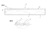
- FIG. 5A is a longitudinal sectional view corresponding to FIG. 3A
- FIG. 5B is an enlarged sectional view of VB of FIG. 5A
- 6 shows another modification of the planar light source device of FIG. 1
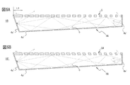
- FIG. 6A is a longitudinal sectional view corresponding to FIG. 3A
- FIG. 6B is a sectional view of the modification of FIG. 6A
- 7 is a longitudinal sectional view corresponding to FIG. 3A of a planar light source device according to another embodiment of the present invention
- FIG. 7B is a sectional view corresponding to FIG. 3A of a modification of the planar light source device of FIG. 7A. is there.
- FIG. 8A to 8C are top views of a large planar light source device in which a plurality of planar light source devices are connected.
- 9A is a perspective view of a planar light source device according to a modification of the present invention
- FIG. 9B is a side view of the planar light source device according to a modification of the present invention.
- FIG. 10A is a top view of a large planar light source device in which a plurality of planar light source devices according to a modification of the present invention are connected
- FIG. 10B is a large planar shape in which a plurality of planar light source devices according to a modification of the present invention are connected.
- FIG. 10C is a side view of a large planar light source device in which a plurality of planar light source devices according to another example of the modification of the present invention are connected.
- 11A to 11C are external perspective views of a planar light source device according to still another embodiment of the present invention.
- 12 shows the planar light source device of FIG. 11A
- FIG. 12A is a top view
- FIG. 12B is an enlarged plan view of a part of the optical reflector of FIG. 12A
- 13 shows a modification of the planar light source device of FIG. 12
- FIG. 13A is a top view
- FIG. 13B is a plan view in which a part of the optical reflector of FIG. 12A is enlarged.
- 14 shows a conventional planar light source
- FIG. 14A is an exploded perspective view
- FIG. 14B is a cross-sectional view taken along the longitudinal direction of FIG. 14A.
- FIG. 15 is a sectional view of a conventional planar light source.
- FIGS. 1 is an external perspective view of a planar light source device according to an embodiment of the present invention
- FIG. 2 is an exploded perspective view of the planar light source device of FIG. 1
- FIG. 3A is a IIIA-IIIA line of FIG. 3B is an enlarged view of the IIIB portion of FIG. 3A
- FIG. 4 shows an optical reflector constituting the planar light source device of FIG. 1
- FIG. 4A is a plan view of the optical reflector
- FIG. FIG. 4C is a general light distribution curve diagram of the LED
- FIG. 4D is a general color characteristic diagram of the LED.
- a planar light source device 1 has a plurality of point light sources having strong directivities, for example, LEDs 2 and these LEDs 2 are arranged at predetermined intervals.
- the LED substrate 3, the main body case 4 having a side wall surface to which the LED substrate 3 is attached and having an opening 4f on the upper side, and a cover body covering the opening 4f of the main body case 4 become substantially uniform and irradiates light from the LED 2 substantially uniformly.
- the optical reflecting plate 5 is provided.
- the planar light source device 1 is an edge light type.
- the planar light source device 1 is used in an illumination device, a display device, or the like by disposing a light diffusing plate as it is or not shown at a predetermined distance from the surface of the optical reflecting plate 5.
- the light diffusion plate is made of a plate-like body such as polyethylene terephthalate (PET) or polycarbonate, and the plate-like body is arranged at a predetermined distance, for example, about 3 mm to 100 mm from the optical reflection plate.
- PET polyethylene terephthalate
- polycarbonate polycarbonate
- the LED 2 uses a single light emitting element or an arbitrary light emitting color composed of an aggregate element in which a plurality of light emitting elements are assembled. When used in a lighting device, a white light LED is preferred. Of course, other light emission colors, for example, red, blue, and green LEDs that are the three primary colors may be used. A laser diode or the like may be used instead of the LED.
- the LED board 3 is formed of a board that is substantially the same size as the one side plate portion 4d of the main body case 4, for example, a heat radiating board that has been subjected to insulation treatment. Are arranged in a substantially single row (array). Note that a plurality of such LED rows may be provided on the LED substrate at predetermined intervals. Illuminance can be increased by using a plurality of LEDs.
- the main body case 4 has a substantially rectangular bottom plate portion 4a having a predetermined area with long sides and short sides opposed to each other, and side plate portions 4b, 4c standing upright from the bottom plate portion at a predetermined height. It consists of a shallow box-like body having 4d and 4e and an opening 4f that opens the top of each side plate, and the inner wall surface is formed of a reflective surface having a high reflectance.
- the body case 4 is formed by cutting / bending a single reflecting plate material or cutting / processing a non-reflecting plate material to form a box and applying a reflecting material to the inner wall surface of the box. To do.
- an ultrafine foamed light reflector (trade name MCPET) is preferably used.
- MCPET ultrafine foamed light reflector
- the latter paint it is preferable to use titanium white fine particles emulsified or polytetrafluoroethylene fine particles (trade name G-80 Hallon).
- the main body case 4 may have any size, but in this embodiment, the height (h 1 + h 2 ) is 15 mm, the short side is 110 mm, and the long side is 180 mm.
- the wall thickness d1 is 1.0 mm (see FIG. 3A).
- the LED substrate 3 is attached to the side plate portion 4d using a known fixing means.
- the optical reflector 5 has front and back surfaces 5a and 5b, opposed long and short sides 5c, 5d, 5e, and 5f, and a predetermined thickness d1, and has an opening in the main body case.
- the front and back surfaces 5a and 5b are reflective surfaces having a high reflectance.
- the back surface 5b is a reflection surface
- the front surface 5a is an illumination light irradiation surface simultaneously with the reflection surface.
- the optical reflector 5 is preferably made of an ultrafine foamed light reflector (trade name MCPET). Of course, it is not limited to this material.
- the optical reflector 5 is attached to the opening 4f of the main body case so that one short side 5e is located on the side facing the LED 2 and the other short side 5f is located on the side away from the LED 2.
- the optical reflecting plate 5 transmits light at a predetermined rate as it moves away from the light shielding region S1 and the light shielding region S1 that shields light from the LED 2 from one short side 5e toward the other short side 5f. It is partitioned into a light transmission region S2.
- the light shielding area S1 is a rectangular area having a predetermined area set in a range from the short side 5e to the predetermined distance L1.
- the light shielding region S1 is formed in a rectangular shape in accordance with the arrangement of the plurality of LEDs 2, that is, in accordance with the linear arrangement of the LEDs.
- the size of the light shielding area S1 is determined in consideration of the following characteristics (light distribution and color characteristics) of the LEDs (i) to (iv) and through holes provided in the light transmission area S2.
- LED element Usually, the fluorescent material is provided in the light emitting element part of LED. For this reason, when the LED is brought close to the optical reflecting plate in order to reduce the thickness, the color of the fluorescent material of the LED, for example, yellow may be projected on the optical reflecting plate. For this reason, the LED cannot be brought close to the optical reflector, and if the LED is forced closer to the optical reflector in order to reduce the thickness, an odd color is projected on the approaching optical reflector. As a result, the lighting quality deteriorates. (Ii) LED Light Distribution Curve As shown in FIG. 4C, the LEDs used in this embodiment have different luminosities depending on the directivity angle ⁇ .
- each LED has a slightly different color characteristic, and it is extremely difficult to prepare the same color characteristics. If the color characteristics of individual LEDs differ, slightly different illumination light is emitted to the optical reflector in the vicinity of the LED, resulting in illumination light other than the desired color, giving a sense of incongruity and lowering illumination quality Will be invited. Hereinafter, the color characteristics of the LED will be added.
- the LED has color characteristics as shown in the chromaticity diagram of FIG. 4D.
- the region W is a white light region, but this region is not a small unit area spot region, and this region includes a plurality of regions such as a cool hot white region, a neutral white region, and the like. It is divided into areas named warm white areas. Each area is further subdivided into a plurality of small areas. These subdivided individual subregions are also called bins. Further, the bin classification is determined by the manufacturer that manufactures the LEDs, and is not shared among the manufacturers, and is not yet standardized.
- a device manufacturer using an LED needs a predetermined color of a specific bin, for example, a white light LED
- the LED of this bin is manufactured by the manufacturer.
- the manufacturing conditions such as manufacturing equipment, manufacturing environment, or production lot, the characteristics of the manufactured LED products vary, and there are many cases that deviate from the target specific bin.
- LED products manufactured under the same conditions have unavoidable variations in their characteristics.
- the manufactured LED products are inspected for each individual product and screened into bins having predetermined characteristics based on the inspection result.
- individual bin classification is individually determined for each manufacturer and is not unified, it is difficult for device manufacturers to obtain LED products having the same characteristics even from the same manufacturer. If it is obtained from another manufacturer, the bin cannot be matched because the bin is not standardized. Therefore, even if the same white light LED is used, there is a difference between the same bins of the same manufacturer as described above, and since the other manufacturers cannot match the bins, the emission color is different. Different ones, for example, one LED is bluish white and the other LED is yellowish white, and colors other than white may be mixed slightly and a desired white light illumination may not be obtained. Note that the same phenomenon occurs with illumination light other than white light.
- the light-transmitting region S2 is provided with a through-hole of a predetermined size as will be described later.
- the through hole is provided so as to satisfy the relational expression x / h 1 > r / d 1 where x is the vertical distance from the light source to the through hole and r is the diameter of the through hole.
- the direct light is more likely to be generated as the distance from the light source is shorter, the direct light is shielded up to a predetermined distance L1 in consideration of the light distribution characteristics of the light source and the distance from the light source to the optical reflector. Region S1 is required.
- the distance L1 of the light shielding region S1 is set to 40.0 mm.
- This distance L1 is set in the prototype test, and is twice or more with respect to 15 mm of the height (h 1 + h 2 ) of the main body case 4.
- the distance (L1) can be solved by setting the distance L1 to more than twice the height. ing. If the area of the light shielding region S1 is increased, the illumination area is limited to be narrow. Therefore, it is preferable to provide a semi-through hole or groove that does not penetrate the reflector near the boundary with the light transmission region S2. These half through-holes or grooves are provided at predetermined intervals so as to be substantially parallel to the short side 5e.
- the light transmission region S2 includes a horizontal imaginary line (not shown) drawn in parallel at a predetermined interval from one long side 5c toward the other long side 5d.
- An opening of a predetermined size is formed at an intersection where a vertical imaginary line (not shown) drawn in parallel at a predetermined interval from the short side 5e to the other short side 5f beyond the light shielding region S1 intersects.
- the horizontal imaginary line includes a plurality of through holes 5 11 to 5 1n ,... 5 m1 to 5 mn having different opening areas
- the vertical imaginary line includes a plurality of opening areas having the same opening area. Through holes 5 11 to 5 m1 ,..., 5 1n to 5 mn are formed.
- a plurality of through holes 5 11 ⁇ 5 1n, ⁇ 5 m1 ⁇ 5 mn through hole row array of similarly through holes 5 11 ⁇ 5 m1, ⁇ 5 1n ⁇ 5 mn is through It has a hole array.
- These through-holes are sized so that the light emitted from the LED 2 cannot pass directly, and the lateral through-holes 5 11 to 5 1n ,... 5 m1 to 5 mn open as the distance from the light-shielding region S1 increases. The area is increased.
- the light from the LED 2 is reflected between the inner wall surface of the main body case 4 and the back surface 5b of the optical reflecting plate 5 and then irradiated to the outside from the through hole.
- the through holes 5 1 and 5 2 close to the light-shielding region S 1 are not directly passed through the through holes 5 1 and 5 2 , and the inner wall surface of the main body case 4
- the reflected light reflected from the back surface 5b of the optical reflector 5 and the reflected light at least once in the through-holes are irradiated to the outside.
- the other through-holes are reflected at least once after being reflected at least once.
- 5 m1 to 5 mn have an opening area that increases with distance from the light-shielding region S1, but the relationship between these opening areas, that is, the opening ratio and the distance. Is a substantially quadratic curve a shown in FIG. 4B.
- the light transmission region S2 is a region close to the light shielding region S1, and because of the reason (ii) above, since the directivity is large, the light intensity may be lowered and darken.
- the opening area of the holes for example, the through-hole rows 5 11 to 5 m1 and 5 12 to 5 m2 is made slightly larger than that of the through-hole rows 5 13 to 5 m3 adjacent thereto.
- the relationship between the aperture ratio and the distance of the optical reflecting plate is a curve a ′ in FIG. 4B.
- the through hole rows 5 11 to 5 m1 closest to the light shielding region S1 have an opening diameter of 3.00 mm, an interval between the openings of 5.00 mm, and the next through hole rows 5 12 to 5 m2 are
- the diameter of the opening is made smaller than 3.00 mm, and in the next through-hole row 5 12 to 5 m 2, the opening is made the smallest and the diameter is 1.5 mm.
- the diameter of the opening is set to 3.8 mm.
- This optical reflector is provided with a circular through-hole having a predetermined opening area in the light transmission region S2, but instead of this through-hole, a narrow groove having a predetermined area, that is, a slit may be used.
- the slits are arranged substantially parallel to the light shielding region S1. Further, instead of the through hole or the slit, a light shielding film in which a portion corresponding to the through hole or the slit is opened may be provided on the transparent substrate.
- the assembly of the planar light source device 1 is completed by attaching the LED substrate 3 on which the LEDs 2 are disposed on one side wall surface of the main body case 4 and covering the opening 4f with the optical reflector 5.
- the light diffusing plate is disposed as necessary at a predetermined distance above the optical reflecting plate.
- the light from the LED 2 is reflected at least once between the inner wall surface of the main body case 4 and the rear surface reflecting surface of the optical reflecting plate 5. It is formed so as to pass through S2 and radiate outward from the irradiation surface. That is, the light is not transmitted from the light shielding region S1, but is irradiated at least once from the light transmitting region S2, that is, multiple reflected and substantially uniformly dispersed. Since the planar light source device 1 is provided with the light-shielding region S1 having a predetermined area on the optical reflection plate 5, even if the plurality of LEDs 2 have variations in color or the like, the color variations are applied to the irradiation surface of the optical reflection plate 5.
- the LED since direct light from the LED 2 does not come out from the optical reflecting plate 5, the LED is not projected on the irradiation surface of the optical reflecting plate 5 even if the optical reflecting plate 5 is brought closer to the LED 2 side. It becomes possible. Furthermore, since the light transmission region S2 has a large opening area of the through hole in the region adjacent to the light shielding region S1 in relation to the light distribution characteristics of the LED, it can be suppressed from becoming dark in this region, and is substantially omitted as a whole. Uniform illumination light can be irradiated.
- the light diffusing plate similarly uses the region corresponding to the light shielding region S1 as the light shielding region. From the region corresponding to the light transmission region S2, the irradiation light that has passed through the optical reflecting plate is irradiated from the irradiation surface of the light diffusing plate between the irradiation surface of the optical reflecting plate and the back surface of the light diffusing plate.
- planar light source device 1 uses the main body case 4 and the optical reflector 5 having the above shapes, these may be changed.
- the planar light source device 1 ⁇ / b> A in FIG. 5A uses an optical reflecting plate 5 ⁇ / b> A instead of the optical reflecting plate 5.
- the optical reflector plate 5A the through hole of the light transmission region S2 is an inclined hole by a predetermined angle theta 1 inclined at steadily declining with respect to the horizontal direction (see FIG. 5B).
- this inclination angle ⁇ 1 is related to the thickness of the optical reflector 5A, it is in the range of 30 ° or more and less than 90 °, preferably more than 45 ° and about 80 °.
- the planar light source device 1 ⁇ / b> A using the optical reflector 5 ⁇ / b> A is less likely to transmit direct light from the LED 2 than the planar light source device 1.
- planar light source device 1B of FIG. 6A uses a main body case 4A in place of the main body case 4.
- the main body case 4A has the side plate portion 4d 'on which the LED 2 is disposed tilted to the left by a predetermined angle with respect to the horizontal direction, and the bottom plate portion 4a' is directed from one side plate portion 4d 'to the other side plate portion 4e'. And tilted by a predetermined angle so as to rise to the right.
- planar light source device 1B ′ of FIG. 6B uses an optical reflecting plate 5A in place of the optical reflecting plate 5 of FIG. 6A.
- the planar light source devices 1B and 1B ′ are obtained by making the optical reflectors 5 and 5A and the side plate portion 4d ′ to which the LED of the main body case is mounted at an acute angle. With this configuration, compared to the planar light source devices 1 and 1A. Thus, the distance between the light shielding regions S1 can be shortened.
- the planar light source devices 1 to 1B ′ are so-called single-sided light source devices in which an optical reflecting plate is attached to the opening of the main body case and light is emitted from the LED 2 from the surface of the optical reflecting plate. You may make it the double-sided type irradiated from another side.
- a planar light source device 1C in FIG. 7A is obtained by using a main body case 4B in which an opening is provided also in the bottom plate portion of the main body case 4, and an optical reflector 5 is attached to both openings, respectively.
- the device 1C ′ has an optical reflecting plate 5A attached to the main body case 4B.
- the planar light source devices 1 to 1C ′ can be connected to each other to constitute a planar light source device and a lighting device having a large light emitting area.
- FIG. 8 shows an example in which one of a plurality of planar light source devices 1 to 1C ′ is connected to increase the light emission area, and the planar light source device 1D in FIG. 8A uses two planar light source devices. These are connected by long side plates, and the planar light source device 1E is connected by short side plates. Furthermore, the planar light source device 1F is obtained by connecting four planar light source devices.
- planar light source devices 1D to 1F may be used as they are, or can be used as an illumination device or a display device by disposing a light diffusion plate (not shown) on the surface of the optical reflection plate. .
- the light shielding region portion may be used as a connecting portion so that a large number can be connected in the optical axis direction of the point light source.
- FIG. 9A is a perspective view of a surface light source device according to a modification of the present invention
- FIG. 9B is a side view of the surface light source device according to a modification of the present invention
- FIG. 10A is a surface light source device according to a modification of the present invention
- FIG. 10B is a side view of a large planar light source device in which a plurality of planar light source devices according to a modification of the present invention are coupled
- FIG. 10C is a modified embodiment of the present invention. It is a side view of the large sized planar light source device which connected several planar light source devices concerning other examples.
- the optical reflecting plate provided with the opening is only on one side, and the height of the short side plate portion attached to the main body case 4 is set to the distance between the optical reflecting plates.
- the short side plate part to which the point light source is attached is erected from the optical reflection plate having no opening, and the short side plate part to which the point light source is not attached is from the optical reflection plate having the opening.
- the height of the long side plate portion that is erected is set to be half the distance between the optical reflecting plates in the length of the light shielding region S1 from both ends, and the inner side is the distance between the optical reflecting plates. That is, the light shielding region S1 and the light transmitting region S2 are separated, and the fitting portion 8a is provided on the light shielding region S1.
- the optical reflecting plate having no opening is provided with a mounting portion 8b having the same area and shape as the fitting portion provided on the light shielding distance S from the side plate portion to which no point light source is attached.
- the fitting portion 8a2 provided on the light shielding region S of the planar light source device 1G2 and a mounting portion for another planar light source device 1G1. 8b1 is coupled.
- the fitting portion 8a3 provided on the light-shielding region S of the planar light source device 1G3 and the mounting portion 8b2 of another planar light source device 1G2 are combined to be continuous in the optical axis direction of the point light source. Can be connected.
- the light shielding region S1 ′ may be formed so as to connect the short side plate portion to which the point light source is attached and the optical reflection plate having the opening at the shortest distance.
- FIGS. 11 shows a surface light source device according to another embodiment of the present invention
- FIG. 11A is a schematic perspective view of a doughnut-shaped surface light source device
- FIG. 11B is a rear view
- FIG. 11C is a surface shape of FIG.
- FIG. 12 shows the planar light source device of FIG. 11, FIG. 12A is a top view, FIG.
- FIG. 12B is an enlarged plan view of a part of the optical reflector of FIG. 13 shows a modification of the planar light source device of FIG. 11, FIG. 13A is a top view, and FIG. 13B is an enlarged plan view of a part of the optical reflector of FIG. 13A.
- FIG. 12A a part of the optical reflector and the inside of the main body case are visible.
- the planar light source device 6 is predetermined at the center of a disk-shaped body having an upper surface opened and a shallow bottom with a predetermined radius r.
- a main body casing 4C having a cylindrical through hole 4C 0 of radius r 1, and is configured by the optical reflector 5B sized to cover the opening of the body case.
- the radii r and r 1 are the lengths from the center point O of the through hole.
- the main body case 4C has a bottom plate portion 4Ca provided with a through hole in the central portion, side plate portions 4Cb and 4Cb ′ erected with a predetermined height around the through hole and the periphery of the bottom plate portion, and an opening in which the top portion of the side plate portion is opened. And have.
- the cylindrical through-hole 4C 0 is composed erected the side plates 4Cb 'from the through hole.
- the main body case 4C may have any size, but in the embodiment shown in FIGS. 11A and 11B, the radii r and r 1 are 275 mm and 120 mm, and the depth (height H1) is 15.0 mm. ing.
- the outer peripheral side is lower than the opening side, that is, the bottom plate part 4Ca ′ is inclined at a predetermined angle from the opening side to the outer peripheral side.
- the height H2 is lower than the height H1 of the planar light source device 6.
- the main body case 4C has an inner wall surface formed as a reflection surface, and the interior thereof is divided into a plurality of parts, for example, six parts. It is divided into small chambers 4C 1 to 4C 6 .
- the partition plate is a support member that supports the optical reflection plate, and both surfaces are formed of reflection surfaces.
- the support member may be a column having a predetermined height instead of the partition plate. As for this support
- the cylindrical through hole 4C 0 has a hexagonal wall surface corresponding to each of the small chambers 4C 1 to 4C 6 .
- the LED board 3 is mounted on these wall surfaces, and the light emitting portion of the LED 2 is exposed to each small chamber.
- the optical reflecting plate 5B has a through hole 5B 0 at a position corresponding to the cylindrical through hole 4C 0 of the main body case 4C, and a light shielding region S1 ′ and a light transmitting region S2 ′ having a predetermined area outward from the through hole. is doing.
- the opening of the main body case 4C is covered with the optical reflecting plate 5B, but the optical reflecting portions 5B 1 to 5B 6 of the optical reflecting plate 5B are located in the openings of the small chambers 4C 1 to 4C 6 .
- These optical reflecting portions 5B 1 to 5B 6 are obtained by dividing one optical reflecting plate 5B into six equal parts and have the same configuration.
- One optical reflection unit 5B 1 will be described with reference to FIG 10B.
- the optical reflection unit 5B 1 has a light-blocking region S1 'and the light transmissive region S2'. These regions S1 ′ and S2 ′ have substantially the same action as the regions S1 and S2 of the optical reflector 5, but the area of the light shielding region S1 ′ and the arrangement of the through holes of the light transmission region S2 ′ are different. Is different.
- the light shielding region S1 ′ has a curved band shape with a predetermined width and a larger area than the light shielding region S1 of the optical reflector 5 shown by the dotted line in FIG. 10B.
- the optical reflector 5 is shown for comparison. This curved strip shape is a circular strip shape between the center point O and the radii r 1 and r 2 .
- This light shielding area S1 ′ is also set in the same manner as the light shielding area S1. Further, in the light transmission region S2 ′, the through hole row is disposed on an arc line having a predetermined radius from the center point O.
- the first row is a through hole row 5 11 ⁇ 5 m1 of radius r 2
- the second row has a through hole row 5 12 ⁇ 5 m2 of radius r 3.
- These through-hole rows are arranged at a predetermined pitch on a concentric circle with a predetermined gap around the center point O in the light transmission region S2 ′ of the optical reflecting plate 5B.
- This planar light source device 6 has the same effects as the planar light source devices 1 to 1B, and is provided with a light diffusing plate as it is or above the optical reflecting plate, for example, a lighting device such as a circular lighting fixture. Can be used as In particular, when used as a lighting fixture, it is preferable that light is slightly transmitted from the bottom plate portion 4Ca and the side plate portion 4Cb.
- the plate material of the main body case is thin, or light transmission means such as a semi-through groove or hole having a predetermined shape is provided on the bottom plate portion and the side plate portion for transmission.
- the planar light source device 6A When light is transmitted from these portions, when the planar light source device is suspended from the ceiling as a lighting fixture, the bottom plate portion side and the side plate portion side do not become dark, so that people do not feel uneasy. Further, when the planar light source device 6A is used as a lighting fixture, the surface light source device 6A can be thinned and the design is improved.
- planar light source device 6C shown in FIG. 13A and FIG. 13B makes the through-holes of the planar light source devices 6 and 6A cylindrical, and changes the shape of the optical reflector 5B ′ in accordance with the through hole. 'Is formed in an arc shape, and this device also has the same function and effect as the planar light source devices 6 and 6A.
- Planar light source device (illumination device) 2 Light emitting diode (LED) 3, 3 'LED substrate 4, 4A to 4C Main body case 4C 0 Through hole 4C 1 to 4C 6 Small chamber 4Ca, 4Ca' Bottom plate portion 5, 5A, 5B Optical reflection plate 5B 1 to 5B 6 Optical reflection portion 5 11 to 5 mn Through-hole 6, 6A to 6C Planar light source device (illumination device) 7 Partition plate S1, S1 ′ Light-shielding region S2, S2 ′ Light transmission region
Landscapes
- Physics & Mathematics (AREA)
- Optics & Photonics (AREA)
- General Physics & Mathematics (AREA)
- Engineering & Computer Science (AREA)
- Nonlinear Science (AREA)
- General Engineering & Computer Science (AREA)
- Mathematical Physics (AREA)
- Chemical & Material Sciences (AREA)
- Crystallography & Structural Chemistry (AREA)
- Microelectronics & Electronic Packaging (AREA)
- Planar Illumination Modules (AREA)
Abstract
Description
LEDは、通常、発光素子部に蛍光材料が設けられている。このため、薄型化を図るためにLEDを光学反射板に接近させると、光学反射板にLEDの蛍光材料の色、例えば黄色が映し出されることがある。そのために、LEDを光学反射板に接近させることができず、また、薄型化を図るために強いてLEDを光学反射板側に接近させると、接近した光学反射板の部分に異様な色が映し出されて見苦しくなり、その結果、照明品質の低下を招くことになる。
(ii)LED配光曲線
本実施例に用いられているLEDは、図4Cに示すように、指向角θにより光度が異なる。すなわち、指向角零度θ0で最も光度が高く、この角度が大きくなるにしたがって光度が低下し、90°で最小となる配光特性を有している。したがって、このLEDの配光特性から、LED近傍の照度が小さくなり暗くなる。
(iii)LEDの色特性
複数個のLEDを使用すると、それぞれのLEDはその色特性が微妙に異なり同一色特性のものを揃えるのが極めて難しい。個々のLEDの色特性が違ってしまうと、LED近傍の光学反射板に微妙に違った照明光が出射されて、所望した色以外の照明光となってしまい、違和感を与えて照明品質の低下を招くことになる。以下、LEDの色特性を付言する。
光透過領域S2には、後述するように所定大きさの貫通孔を設けるが、この貫通孔からLEDからの発光光が直接透過(通過)されると、従来技術と同様の課題が生じることになる。すなわち、光源から貫通孔までの垂直距離をx、貫通孔の径をrとすると、x/h1>r/d1なる関係式を満たすように、貫通孔が設けられている。また、このダイレクト光は、光源からの距離が近ければ近いほど発生し易くなるので、光源の配光特性や光源から光学反射板までの距離などを考慮した、所定の距離L1までを遮光する遮光領域S1が必要になる。
2 発光ダイオード(LED)
3、3' LED基板
4、4A~4C 本体ケース
4C0 貫通孔
4C1~4C6 小室
4Ca、4Ca' 底板部
5、5A、5B 光学反射板
5B1~5B6 光学反射部
511~5mn 貫通孔
6、6A~6C 面状光源装置(照明装置)
7 仕切り板
S1、S1' 遮光領域
S2、S2' 光透過領域
Claims (11)
- 所定の隙間をあけて対向配設した一対の光学反射板間の周囲を側板で囲った本体ケースと、前記本体ケースの少なくとも一側板に複数個の点光源を所定の間隔をあけて配列して、前記一対の光学反射板の少なくとも一方から前記点光源からの光を透過させて外部へ出射する面状光源装置であって、
前記一対の光学反射板の少なくとも一方は、前記点光源側に前記点光源からの光を遮光する遮光領域と、前記点光源からの光を直接透過させず前記光学反射板間で反射させた反射光を透過させ、該遮光領域から離れるにしたがって透過率が増大し、且つ、該光学反射板の表面で輝度が実質的に均一になるように調整された光透過領域が設けられていることを特徴とする面状光源装置。 - 前記光透過領域は、前記点光源の配光特性に基づいて該光透過領域の表面で輝度が均一になるように調整されていることを特徴とする請求項1に記載の面状光源装置。
- 前記光透過領域は、前記光学反射板を貫通する複数の貫通孔又はスリットが配設されていることを特徴とする請求項2に記載の面状光源装置。
- 前記遮光領域は、前記一対の光学反射板間の隙間より幅広の領域で形成されていることを特徴とする請求項1に記載の面状光源装置。
- 前記遮光領域と前記光透過領域とが分離されており、前記遮光領域から対向する前記光学反射板との距離は、前記光透過領域から前記光透過領域と対向する前記光学反射板との距離の半分であることを特徴とする請求項1に記載の面状光源装置。
- 浅底で該底部と対向した面が開口し所定深さの円盤状体の中心部に貫通孔を設けた本体ケースと、前記本体ケースの開口を塞いだ光学反射板と、前記本体ケースの前記貫通孔の壁面に点光源を配設して、前記点光源からの光を前記本体ケースの内壁面と前記光学反射板との間で反射させて外部へ出射する面状光源装置であって、
前記光学反射板は、前記点光源側に前記点光源からの光を遮光する遮光領域と、前記点光源からの光を直接透過させず前記光学反射板間で反射させた反射光を透過させ、該遮光領域から離れるにしたがって透過率が増大し、且つ、該光学反射板の表面で輝度が実質的に均一になるように調整された光透過領域が設けられていることを特徴とする面状光源装置。 - 前記光学反射板は、前記本体ケースの貫通孔の周囲に前記遮光領域と、前記遮光領域の周囲に前記光透過領域が設けられていることを特徴とする請求項6に記載の面状光源装置。
- 前記光透過領域は、前記点光源の配光特性に基づいて該光透過領域の表面で輝度が均一となるように調整されていることを特徴とする請求項7に記載の面状光源装置。
- 前記光透過領域は、前記光学反射板を貫通する複数の貫通孔又はスリットが前記貫通孔を中心にして同心円上に配設されていることを特徴とする請求項8に記載の面状光源装置。
- 請求項1~9のいずれかの面状光源装置が少なくとも1個配設されていることを特徴とする照明装置。
- 請求項1~9のいずれかの面状光源装置が少なくとも1個配設されて、それらの照明面上に光拡散板が設けられていることを特徴とする照明装置。
Priority Applications (5)
| Application Number | Priority Date | Filing Date | Title |
|---|---|---|---|
| KR1020127032072A KR20130082084A (ko) | 2010-06-08 | 2011-06-08 | 면형상 광원 장치 및 조명 장치 |
| US13/702,025 US8911133B2 (en) | 2010-06-08 | 2011-06-08 | Planar light source device and illumination apparatus |
| EP11792494.4A EP2581641B1 (en) | 2010-06-08 | 2011-06-08 | Planar light source device and illumination apparatus |
| CN2011800278810A CN102933894A (zh) | 2010-06-08 | 2011-06-08 | 面状光源装置以及照明装置 |
| JP2012519418A JP5463462B2 (ja) | 2010-06-08 | 2011-06-08 | 面状光源装置及び照明装置 |
Applications Claiming Priority (2)
| Application Number | Priority Date | Filing Date | Title |
|---|---|---|---|
| JP2010-131540 | 2010-06-08 | ||
| JP2010131540 | 2010-06-08 |
Publications (1)
| Publication Number | Publication Date |
|---|---|
| WO2011155537A1 true WO2011155537A1 (ja) | 2011-12-15 |
Family
ID=45098141
Family Applications (1)
| Application Number | Title | Priority Date | Filing Date |
|---|---|---|---|
| PCT/JP2011/063161 WO2011155537A1 (ja) | 2010-06-08 | 2011-06-08 | 面状光源装置及び照明装置 |
Country Status (6)
| Country | Link |
|---|---|
| US (1) | US8911133B2 (ja) |
| EP (1) | EP2581641B1 (ja) |
| JP (1) | JP5463462B2 (ja) |
| KR (1) | KR20130082084A (ja) |
| CN (1) | CN102933894A (ja) |
| WO (1) | WO2011155537A1 (ja) |
Cited By (11)
| Publication number | Priority date | Publication date | Assignee | Title |
|---|---|---|---|---|
| CN102997096A (zh) * | 2012-11-19 | 2013-03-27 | 无锡莱吉特信息科技有限公司 | 一种无导光板侧入光面光源 |
| WO2013099786A1 (ja) * | 2011-12-28 | 2013-07-04 | シャープ株式会社 | 照明装置、バックライト、液晶表示装置及びテレビジョン受像機 |
| WO2014013745A1 (en) * | 2012-07-20 | 2014-01-23 | Sharp Kabushiki Kaisha | Lighting device and method for providing light |
| WO2014024063A1 (en) * | 2012-08-09 | 2014-02-13 | Koninklijke Philips N.V. | Lamp for natural lighting experience. |
| WO2014097042A1 (en) * | 2012-12-18 | 2014-06-26 | Koninklijke Philips N.V. | Sound absorbing lighting panel and modular surface system |
| JP2015022303A (ja) * | 2013-07-23 | 2015-02-02 | 友達光電股▲ふん▼有限公司AU Optronics Corporation | 表示装置 |
| JP2019511828A (ja) * | 2016-04-22 | 2019-04-25 | シグニファイ ホールディング ビー ヴィ | 一体化された空気ガイド及びビーム成形 |
| JP2019067553A (ja) * | 2017-09-29 | 2019-04-25 | 大日本印刷株式会社 | 発光パネル |
| US10520141B2 (en) | 2016-04-22 | 2019-12-31 | Signify Holding B.V. | Integrated air guide and beam shaping |
| EP2857890B1 (en) * | 2012-05-31 | 2020-04-29 | BOE Technology Group Co., Ltd. | Surface light source device and edge backlight module |
| KR102217600B1 (ko) * | 2019-10-17 | 2021-02-19 | 현대모비스 주식회사 | 라이트가이드 장치 및 이의 순차적 점등방법 |
Families Citing this family (35)
| Publication number | Priority date | Publication date | Assignee | Title |
|---|---|---|---|---|
| TWI539115B (zh) * | 2012-11-16 | 2016-06-21 | 鴻海精密工業股份有限公司 | 導光元件及光源模組 |
| WO2014192659A1 (ja) * | 2013-05-28 | 2014-12-04 | 堺ディスプレイプロダクト株式会社 | 光源装置及び表示装置 |
| CN104344280A (zh) | 2013-07-31 | 2015-02-11 | 扬升照明股份有限公司 | 光源模块 |
| TWI540404B (zh) | 2013-08-23 | 2016-07-01 | 冠晶光電股份有限公司 | 可切換晝夜模式之照明調光裝置及其調光方法 |
| DE102013017742A1 (de) * | 2013-10-28 | 2015-04-30 | Airbus Defence and Space GmbH | Hohler Lichtleiter mit Öffnungen, insbesondere zur Versorgung eines Photobioreaktors mit Licht und Nährstoffen |
| KR102097591B1 (ko) * | 2013-10-30 | 2020-04-07 | 재단법인 포항산업과학연구원 | 실감 조명 장치 |
| CN104633531A (zh) * | 2013-11-11 | 2015-05-20 | 富泰华精密电子(郑州)有限公司 | 侧入式背光模组 |
| CN104676354A (zh) * | 2013-11-28 | 2015-06-03 | 富泰华精密电子(郑州)有限公司 | 背光模组 |
| DE102013019889B4 (de) * | 2013-11-28 | 2015-07-30 | Airbus Defence and Space GmbH | Photobioreaktor mit Matten aus licht-auskoppelnden Lichtleiterfasern und ein elektrisches Wanderfeld erzeugenden elektrisch leitfähigen Fasern |
| US9803833B2 (en) * | 2013-12-03 | 2017-10-31 | X Development Llc | Multi-aperture illumination layer for tileable display |
| KR102222433B1 (ko) | 2014-09-01 | 2021-03-04 | 삼성디스플레이 주식회사 | 백라이트 유닛 및 이를 포함하는 표시 장치 |
| TWI622839B (zh) * | 2014-09-11 | 2018-05-01 | 友達光電股份有限公司 | 背光模組 |
| TWI557474B (zh) * | 2014-09-16 | 2016-11-11 | 友達光電股份有限公司 | 雙面背光模組 |
| CN104296008A (zh) * | 2014-10-10 | 2015-01-21 | 京东方科技集团股份有限公司 | 背光模组及显示装置 |
| CN104791668A (zh) * | 2015-04-30 | 2015-07-22 | 深圳市华星光电技术有限公司 | 背光模块及具有该背光模块的液晶显示器 |
| US20160327241A1 (en) * | 2015-05-04 | 2016-11-10 | 3M Innovative Properties Company | Luminaire assembly |
| US9842475B2 (en) * | 2015-05-21 | 2017-12-12 | Block And Company, Inc. | Illuminated cash drawer |
| KR101684117B1 (ko) * | 2015-05-27 | 2016-12-07 | 현대자동차주식회사 | 차량용 무드등 |
| TWI567460B (zh) * | 2015-12-11 | 2017-01-21 | 友達光電股份有限公司 | 背光模組 |
| US9772439B2 (en) | 2016-02-05 | 2017-09-26 | Sharp Kabushiki Kaisha | Thin backlight with reduced bezel width |
| US10649130B2 (en) * | 2016-04-22 | 2020-05-12 | Signify Holding B.V. | Pebble-plate like louvre with specific domain characteristics |
| US9921357B2 (en) | 2016-06-21 | 2018-03-20 | Sharp Kabushiki Kaisha | Thin backlight with recycling to reduce the bezel width |
| KR102693625B1 (ko) | 2016-12-08 | 2024-08-09 | 엘지이노텍 주식회사 | 조명장치 및 이를 포함하는 차량용 램프 |
| WO2018143039A1 (ja) * | 2017-01-31 | 2018-08-09 | シャープ株式会社 | 照明装置及び表示装置 |
| CN106873072B (zh) | 2017-04-24 | 2019-06-14 | 京东方科技集团股份有限公司 | 导光组件及其制备方法、背光模组和显示装置 |
| EP3735559B1 (en) * | 2018-01-02 | 2021-06-30 | Signify Holding B.V. | Lighting module, kit and panel |
| US20190271445A1 (en) * | 2018-03-01 | 2019-09-05 | Dell Products L.P. | System and method for producing indicator light assembly with plastic housing |
| US10594121B2 (en) | 2018-07-09 | 2020-03-17 | Vynckier Enclosure Systems, Inc. | Weatherproof multipurpose enclosure with integrated flashing |
| USD1015279S1 (en) | 2018-07-09 | 2024-02-20 | Hoffman Enclosures Inc. | Rooftop junction box |
| KR102185885B1 (ko) * | 2018-08-20 | 2020-12-02 | 구본길 | 진열장용 led 조명장치 |
| CN111208670A (zh) * | 2018-11-22 | 2020-05-29 | 瑞仪(广州)光电子器件有限公司 | 发光机构、背光模块及其显示设备 |
| KR102668143B1 (ko) * | 2019-01-03 | 2024-05-24 | 삼성디스플레이 주식회사 | 표시장치 |
| CN113454525A (zh) * | 2019-02-21 | 2021-09-28 | 美蓓亚三美株式会社 | 面状照明装置 |
| CN110264869B (zh) * | 2019-06-11 | 2022-04-01 | 惠科股份有限公司 | 光学调控结构、背光模组及显示装置 |
| CN113236991B (zh) * | 2021-04-16 | 2022-10-28 | 欧普照明股份有限公司 | 一种台灯 |
Citations (5)
| Publication number | Priority date | Publication date | Assignee | Title |
|---|---|---|---|---|
| JPH08153405A (ja) | 1994-06-21 | 1996-06-11 | Nakaya:Kk | 面状光源 |
| JP2001236811A (ja) | 2000-02-23 | 2001-08-31 | Fujitsu Kasei Kk | 照明装置 |
| JP2005099406A (ja) | 2003-09-25 | 2005-04-14 | Nissan Steel Kogyo Kk | レジ案内灯 |
| JP2005149848A (ja) | 2003-11-13 | 2005-06-09 | Iwasaki Electric Co Ltd | 発光ダイオードを用いた照明装置 |
| JP2010062138A (ja) * | 2008-08-06 | 2010-03-18 | Opt Design:Kk | 光源装置、照明装置および表示装置 |
Family Cites Families (10)
| Publication number | Priority date | Publication date | Assignee | Title |
|---|---|---|---|---|
| JPH08297282A (ja) * | 1994-05-27 | 1996-11-12 | Canon Inc | バックライト装置及びそれを用いた表示装置 |
| EP1113218B1 (en) * | 1999-12-28 | 2007-02-07 | Fujitsu Kasei Limited | Lighting apparatus for a display |
| US7263268B2 (en) * | 2001-07-23 | 2007-08-28 | Ben-Zion Inditsky | Ultra thin radiation management and distribution systems with hybrid optical waveguide |
| US7417782B2 (en) * | 2005-02-23 | 2008-08-26 | Pixtronix, Incorporated | Methods and apparatus for spatial light modulation |
| US20070165154A1 (en) * | 2006-01-18 | 2007-07-19 | 3M Innovative Properties Company | Display device and method of controlling light therein |
| JP4544182B2 (ja) * | 2006-03-08 | 2010-09-15 | エプソンイメージングデバイス株式会社 | 照明装置、電気光学装置及びその製造方法 |
| US7660509B2 (en) * | 2006-05-24 | 2010-02-09 | 3M Innovative Properties Company | Backlight asymmetric light input wedge |
| US7513634B2 (en) * | 2007-05-21 | 2009-04-07 | National Tsing Hua University | Structure of planar illuminator |
| TW200949157A (en) * | 2008-02-08 | 2009-12-01 | 3M Innovative Properties Co | Perforated backlight |
| CN101604097B (zh) * | 2008-06-13 | 2011-06-22 | 群康科技(深圳)有限公司 | 背光模组及液晶显示装置 |
-
2011
- 2011-06-08 US US13/702,025 patent/US8911133B2/en not_active Expired - Fee Related
- 2011-06-08 JP JP2012519418A patent/JP5463462B2/ja not_active Expired - Fee Related
- 2011-06-08 CN CN2011800278810A patent/CN102933894A/zh active Pending
- 2011-06-08 EP EP11792494.4A patent/EP2581641B1/en not_active Not-in-force
- 2011-06-08 KR KR1020127032072A patent/KR20130082084A/ko not_active Application Discontinuation
- 2011-06-08 WO PCT/JP2011/063161 patent/WO2011155537A1/ja active Application Filing
Patent Citations (5)
| Publication number | Priority date | Publication date | Assignee | Title |
|---|---|---|---|---|
| JPH08153405A (ja) | 1994-06-21 | 1996-06-11 | Nakaya:Kk | 面状光源 |
| JP2001236811A (ja) | 2000-02-23 | 2001-08-31 | Fujitsu Kasei Kk | 照明装置 |
| JP2005099406A (ja) | 2003-09-25 | 2005-04-14 | Nissan Steel Kogyo Kk | レジ案内灯 |
| JP2005149848A (ja) | 2003-11-13 | 2005-06-09 | Iwasaki Electric Co Ltd | 発光ダイオードを用いた照明装置 |
| JP2010062138A (ja) * | 2008-08-06 | 2010-03-18 | Opt Design:Kk | 光源装置、照明装置および表示装置 |
Non-Patent Citations (2)
| Title |
|---|
| HARISON TOSHIBA LIGHTING CORP.: "Shomei-yo Chuku Unit, Japan Institute of Invention and Innovation, Journal of Technical Disclosure", JAPAN INSTITUTE OF INVENTION AND INNOVATION, JOURNAL OF TECHNICAL DISCLOSURE NO.2010-502040, 2 April 2010 (2010-04-02), XP008168140 * |
| See also references of EP2581641A4 |
Cited By (15)
| Publication number | Priority date | Publication date | Assignee | Title |
|---|---|---|---|---|
| WO2013099786A1 (ja) * | 2011-12-28 | 2013-07-04 | シャープ株式会社 | 照明装置、バックライト、液晶表示装置及びテレビジョン受像機 |
| EP2857890B1 (en) * | 2012-05-31 | 2020-04-29 | BOE Technology Group Co., Ltd. | Surface light source device and edge backlight module |
| JP2015521780A (ja) * | 2012-07-20 | 2015-07-30 | シャープ株式会社 | 発光装置、および光供給方法 |
| WO2014013745A1 (en) * | 2012-07-20 | 2014-01-23 | Sharp Kabushiki Kaisha | Lighting device and method for providing light |
| WO2014024063A1 (en) * | 2012-08-09 | 2014-02-13 | Koninklijke Philips N.V. | Lamp for natural lighting experience. |
| CN102997096A (zh) * | 2012-11-19 | 2013-03-27 | 无锡莱吉特信息科技有限公司 | 一种无导光板侧入光面光源 |
| WO2014097042A1 (en) * | 2012-12-18 | 2014-06-26 | Koninklijke Philips N.V. | Sound absorbing lighting panel and modular surface system |
| US9822938B2 (en) | 2012-12-18 | 2017-11-21 | Philips Lighting Holding B.V. | Sound absorbing lighting panel and modular surface system |
| RU2660406C2 (ru) * | 2012-12-18 | 2018-07-06 | Филипс Лайтинг Холдинг Б.В. | Звукопоглощающая осветительная панель и модульная поверхностная система |
| JP2015022303A (ja) * | 2013-07-23 | 2015-02-02 | 友達光電股▲ふん▼有限公司AU Optronics Corporation | 表示装置 |
| JP2019511828A (ja) * | 2016-04-22 | 2019-04-25 | シグニファイ ホールディング ビー ヴィ | 一体化された空気ガイド及びビーム成形 |
| US10520141B2 (en) | 2016-04-22 | 2019-12-31 | Signify Holding B.V. | Integrated air guide and beam shaping |
| JP2019067553A (ja) * | 2017-09-29 | 2019-04-25 | 大日本印刷株式会社 | 発光パネル |
| JP7110574B2 (ja) | 2017-09-29 | 2022-08-02 | 大日本印刷株式会社 | 発光パネル |
| KR102217600B1 (ko) * | 2019-10-17 | 2021-02-19 | 현대모비스 주식회사 | 라이트가이드 장치 및 이의 순차적 점등방법 |
Also Published As
| Publication number | Publication date |
|---|---|
| JPWO2011155537A1 (ja) | 2013-08-01 |
| EP2581641A4 (en) | 2016-08-10 |
| CN102933894A (zh) | 2013-02-13 |
| US8911133B2 (en) | 2014-12-16 |
| KR20130082084A (ko) | 2013-07-18 |
| US20130077345A1 (en) | 2013-03-28 |
| EP2581641B1 (en) | 2017-08-23 |
| JP5463462B2 (ja) | 2014-04-09 |
| EP2581641A1 (en) | 2013-04-17 |
Similar Documents
| Publication | Publication Date | Title |
|---|---|---|
| JP5463462B2 (ja) | 面状光源装置及び照明装置 | |
| US9291767B2 (en) | Free form lighting module | |
| US8640368B2 (en) | Light source device, lighting device, and display device | |
| JP5648162B2 (ja) | 面光源ユニット、面照明装置及び液晶表示装置 | |
| JP4764962B2 (ja) | 面照明光源装置及び面照明装置 | |
| US9268082B2 (en) | Free form lighting module | |
| KR100944599B1 (ko) | 면조명 광원장치 및 이것을 이용한 면조명장치 | |
| JP5475684B2 (ja) | 照明システム、照明器具及びバックライトユニット | |
| WO2011040493A1 (ja) | 照明光の色補正方法、この色補正方法を採用した光源モジュール及び照明装置 | |
| JPH09503596A (ja) | 裏面照明のための光源 | |
| KR20120133153A (ko) | 점광원을 이용한 면발광 백라이트 유닛 및 면발광 램프 | |
| JP5467280B2 (ja) | 照明装置 | |
| JP5816908B2 (ja) | Led光源装置及びこの光源装置を用いた照明装置 | |
| JP2011150861A (ja) | Led光源装置及びこの光源装置を用いた照明装置 | |
| JP6501378B1 (ja) | スリットを有するレンズ | |
| JP2010205515A (ja) | 面照明ユニット及びこの面照明ユニットを用いた面照明装置 | |
| JP4848534B2 (ja) | 面状光源 | |
| WO2020196572A1 (ja) | 面光源装置および表示装置 | |
| WO2019097985A1 (ja) | 面光源装置および表示装置 | |
| KR20120042062A (ko) | 회절 렌즈를 구비한 액정표시장치용 직하형 백 라이트 유닛 |
Legal Events
| Date | Code | Title | Description |
|---|---|---|---|
| WWE | Wipo information: entry into national phase |
Ref document number: 201180027881.0 Country of ref document: CN |
|
| 121 | Ep: the epo has been informed by wipo that ep was designated in this application |
Ref document number: 11792494 Country of ref document: EP Kind code of ref document: A1 |
|
| WWE | Wipo information: entry into national phase |
Ref document number: 13702025 Country of ref document: US |
|
| WWE | Wipo information: entry into national phase |
Ref document number: 2012519418 Country of ref document: JP |
|
| ENP | Entry into the national phase |
Ref document number: 20127032072 Country of ref document: KR Kind code of ref document: A |
|
| REEP | Request for entry into the european phase |
Ref document number: 2011792494 Country of ref document: EP |
|
| WWE | Wipo information: entry into national phase |
Ref document number: 2011792494 Country of ref document: EP |
|
| NENP | Non-entry into the national phase |
Ref country code: DE |