WO2011151932A1 - 車両用スタータリングギヤ - Google Patents
車両用スタータリングギヤ Download PDFInfo
- Publication number
- WO2011151932A1 WO2011151932A1 PCT/JP2010/063509 JP2010063509W WO2011151932A1 WO 2011151932 A1 WO2011151932 A1 WO 2011151932A1 JP 2010063509 W JP2010063509 W JP 2010063509W WO 2011151932 A1 WO2011151932 A1 WO 2011151932A1
- Authority
- WO
- WIPO (PCT)
- Prior art keywords
- gear
- vehicle
- outer peripheral
- starter
- engine
- Prior art date
- Legal status (The legal status is an assumption and is not a legal conclusion. Google has not performed a legal analysis and makes no representation as to the accuracy of the status listed.)
- Ceased
Links
Images





Classifications
-
- F—MECHANICAL ENGINEERING; LIGHTING; HEATING; WEAPONS; BLASTING
- F02—COMBUSTION ENGINES; HOT-GAS OR COMBUSTION-PRODUCT ENGINE PLANTS
- F02N—STARTING OF COMBUSTION ENGINES; STARTING AIDS FOR SUCH ENGINES, NOT OTHERWISE PROVIDED FOR
- F02N11/00—Starting of engines by means of electric motors
-
- B—PERFORMING OPERATIONS; TRANSPORTING
- B23—MACHINE TOOLS; METAL-WORKING NOT OTHERWISE PROVIDED FOR
- B23K—SOLDERING OR UNSOLDERING; WELDING; CLADDING OR PLATING BY SOLDERING OR WELDING; CUTTING BY APPLYING HEAT LOCALLY, e.g. FLAME CUTTING; WORKING BY LASER BEAM
- B23K9/00—Arc welding or cutting
- B23K9/02—Seam welding; Backing means; Inserts
- B23K9/028—Seam welding; Backing means; Inserts for curved planar seams
-
- B—PERFORMING OPERATIONS; TRANSPORTING
- B23—MACHINE TOOLS; METAL-WORKING NOT OTHERWISE PROVIDED FOR
- B23K—SOLDERING OR UNSOLDERING; WELDING; CLADDING OR PLATING BY SOLDERING OR WELDING; CUTTING BY APPLYING HEAT LOCALLY, e.g. FLAME CUTTING; WORKING BY LASER BEAM
- B23K26/00—Working by laser beam, e.g. welding, cutting or boring
- B23K26/20—Bonding
- B23K26/21—Bonding by welding
- B23K26/24—Seam welding
- B23K26/28—Seam welding of curved planar seams
-
- F—MECHANICAL ENGINEERING; LIGHTING; HEATING; WEAPONS; BLASTING
- F02—COMBUSTION ENGINES; HOT-GAS OR COMBUSTION-PRODUCT ENGINE PLANTS
- F02N—STARTING OF COMBUSTION ENGINES; STARTING AIDS FOR SUCH ENGINES, NOT OTHERWISE PROVIDED FOR
- F02N15/00—Other power-operated starting apparatus; Component parts, details, or accessories, not provided for in, or of interest apart from groups F02N5/00 - F02N13/00
- F02N15/006—Assembling or mounting of starting devices
-
- F—MECHANICAL ENGINEERING; LIGHTING; HEATING; WEAPONS; BLASTING
- F16—ENGINEERING ELEMENTS AND UNITS; GENERAL MEASURES FOR PRODUCING AND MAINTAINING EFFECTIVE FUNCTIONING OF MACHINES OR INSTALLATIONS; THERMAL INSULATION IN GENERAL
- F16H—GEARING
- F16H55/00—Elements with teeth or friction surfaces for conveying motion; Worms, pulleys or sheaves for gearing mechanisms
- F16H55/02—Toothed members; Worms
- F16H55/17—Toothed wheels
-
- B—PERFORMING OPERATIONS; TRANSPORTING
- B23—MACHINE TOOLS; METAL-WORKING NOT OTHERWISE PROVIDED FOR
- B23K—SOLDERING OR UNSOLDERING; WELDING; CLADDING OR PLATING BY SOLDERING OR WELDING; CUTTING BY APPLYING HEAT LOCALLY, e.g. FLAME CUTTING; WORKING BY LASER BEAM
- B23K2101/00—Articles made by soldering, welding or cutting
- B23K2101/008—Gears
-
- F—MECHANICAL ENGINEERING; LIGHTING; HEATING; WEAPONS; BLASTING
- F02—COMBUSTION ENGINES; HOT-GAS OR COMBUSTION-PRODUCT ENGINE PLANTS
- F02N—STARTING OF COMBUSTION ENGINES; STARTING AIDS FOR SUCH ENGINES, NOT OTHERWISE PROVIDED FOR
- F02N11/00—Starting of engines by means of electric motors
- F02N11/08—Circuits specially adapted for starting of engines
- F02N11/0814—Circuits specially adapted for starting of engines comprising means for controlling automatic idle-start-stop
- F02N11/0818—Conditions for starting or stopping the engine or for deactivating the idle-start-stop mode
- F02N11/0822—Conditions for starting or stopping the engine or for deactivating the idle-start-stop mode related to action of the driver
-
- F—MECHANICAL ENGINEERING; LIGHTING; HEATING; WEAPONS; BLASTING
- F02—COMBUSTION ENGINES; HOT-GAS OR COMBUSTION-PRODUCT ENGINE PLANTS
- F02N—STARTING OF COMBUSTION ENGINES; STARTING AIDS FOR SUCH ENGINES, NOT OTHERWISE PROVIDED FOR
- F02N15/00—Other power-operated starting apparatus; Component parts, details, or accessories, not provided for in, or of interest apart from groups F02N5/00 - F02N13/00
- F02N15/02—Gearing between starting-engines and started engines; Engagement or disengagement thereof
- F02N15/04—Gearing between starting-engines and started engines; Engagement or disengagement thereof the gearing including disengaging toothed gears
- F02N15/06—Gearing between starting-engines and started engines; Engagement or disengagement thereof the gearing including disengaging toothed gears the toothed gears being moved by axial displacement
- F02N15/067—Gearing between starting-engines and started engines; Engagement or disengagement thereof the gearing including disengaging toothed gears the toothed gears being moved by axial displacement the starter comprising an electro-magnetically actuated lever
-
- Y—GENERAL TAGGING OF NEW TECHNOLOGICAL DEVELOPMENTS; GENERAL TAGGING OF CROSS-SECTIONAL TECHNOLOGIES SPANNING OVER SEVERAL SECTIONS OF THE IPC; TECHNICAL SUBJECTS COVERED BY FORMER USPC CROSS-REFERENCE ART COLLECTIONS [XRACs] AND DIGESTS
- Y10—TECHNICAL SUBJECTS COVERED BY FORMER USPC
- Y10T—TECHNICAL SUBJECTS COVERED BY FORMER US CLASSIFICATION
- Y10T74/00—Machine element or mechanism
- Y10T74/13—Machine starters
- Y10T74/131—Automatic
- Y10T74/137—Reduction gearing
Definitions
- the present invention relates to a vehicle starter gear used for starting an engine, and more particularly to a technique for suppressing a decrease in hardness of outer peripheral teeth of the vehicle starter gear.
- a plurality of locations are welded to the disk-shaped member in a state of being fitted to the outer peripheral surface of the disk-shaped member that rotates with the engine and has an annular shape, and starts the engine. Therefore, there is known a vehicle starter gear that is rotationally driven by a starter motor having a pinion gear that can mesh with the outer peripheral teeth. For example, those described in Patent Documents 1 and 2.
- the starter gear of Patent Document 1 is welded to a cover of a torque converter as a disk-shaped member that rotates with the engine.
- the startering gear of Patent Document 2 is welded to, for example, a disk-shaped drive plate as a disk-shaped member that is fixed to a torque converter cover and rotates with the engine.
- the vehicle starter gear includes, for example, a ring-shaped member formed by bending a rod-shaped drawing material into an annular shape and welding the end surfaces thereof to each other, and an outer peripheral surface of the annular member.
- a gear cutting tool such as a hob is used to form outer peripheral teeth, and the outer peripheral teeth are subjected to induction hardening, carburizing hardening, and the like.
- the present invention has been made against the background of the above circumstances, and the object of the present invention is to provide a vehicle starter that can suppress a decrease in the hardness of outer peripheral teeth that occurs during welding with a disk-shaped member. It is to provide a ring gear.
- the gist of the invention according to claim 1 for achieving the above object is that a disk-shaped member having outer peripheral teeth and (a) a circular member having outer peripheral teeth and rotating together with the engine.
- a startering gear for a vehicle wherein (b) a welded portion between at least the vehicular startering gear and the disk-shaped member among the inner peripheral surface of the vehicular startering gear and the tooth surface of the outer peripheral teeth
- gear is provided in the outer peripheral side.
- the thermal resistance portion is formed in a circumferential groove or a tangential direction formed in a circumferential direction on a side surface of the vehicle starter gear. It is in the formed linear groove.
- the gist of the invention according to claim 3 is that, in the invention according to claim 1, the thermal resistance portion is an annular groove formed continuously on the side surface of the vehicle starter gear over the entire circumference. There is.
- the thermal resistance portion is formed so as to penetrate from one side surface of the vehicle starter gear to the other side surface. There is a through hole.
- the gist of the invention according to claim 5 is that, in the invention according to claim 2 or 3, (a) the pinion gear does not mesh with the meshing position where the pinion gear meshes with the vehicle starter gear and the vehicle starter gear.
- the vehicle starter gear is rotationally driven by the starter motor, the vehicle starter gear is moved to the meshing position.
- the vehicle starter ring gear is not rotationally driven by the starter motor, the vehicle starter gear is moved to the non-meshing position, and (b) the heat resistance portion is located at the non-meshing position.
- One of the vehicle starter gears opposed to the rotation center line in a direction parallel to the rotation center line When welding with the said disk-shaped member is given to the side surface, it exists in providing in the one side surface.
- the vehicle starter gear according to any one of the first to fifth aspects, wherein the engine is temporarily stopped automatically when the vehicle is stopped. At the same time, when the vehicle is started to travel, the engine is restarted. When the engine automatic stop / start control is executed, the starter motor is rotationally driven to restart the engine.
- the welding between at least the startering gear for a vehicle and the disk-shaped member among the inner peripheral surface of the vehicle starter gear and the tooth surface of the outer peripheral tooth Since the heat resistance part which suppresses the heat at the time of welding of the welding part to be conducted to the outer peripheral tooth is provided on the outer peripheral side of the part, for example, the hardness of the outer peripheral tooth is increased by induction hardening or carburizing hardening.
- the raised vehicle starter gear is welded to the disk-shaped member in a state where the vehicle starter gear is fitted to the outer peripheral surface of the disk-shaped member, heat during the welding is conducted to the outer peripheral teeth. Since the peripheral teeth are suppressed from being annealed, it is possible to suppress a decrease in the hardness of the peripheral teeth that occurs during welding with the disk-shaped member. The amount of wear caused by the engagement with the pinion gear can be reduced.
- the thermal resistance portion is a circumferential groove formed in a circumferential direction or a straight groove formed in a tangential direction on a side surface of the vehicle starter gear. Therefore, when there is a circumferential groove or a straight groove on the outer peripheral side of the welded portion between the vehicle starter gear and the disk-shaped member, the welding portion is more welded than when there is no groove. Since heat is hardly transmitted from the welded portion to the outer peripheral teeth, the outer peripheral teeth are prevented from being annealed during welding with the disk-shaped member, and the hardness of the outer peripheral teeth is prevented from being reduced. it can.
- the thermal resistance portion is an annular groove formed continuously on the side surface of the vehicle starter gear over the entire circumference, the vehicle starter Since there is an annular groove on the outer peripheral side of the welded portion between the ring gear and the disk-shaped member, the heat at the time of welding of the welded portion is transmitted from the welded portion to the outer peripheral teeth compared to when there is no annular groove. Therefore, it is possible to suppress the outer peripheral teeth from being annealed at the time of welding with the disk-shaped member, and it is possible to suppress a decrease in the hardness of the outer peripheral teeth.
- the annular groove formed continuously over the entire circumference has an advantage that it is easy to process compared to the circumferential groove formed in a part of the circumferential direction, and reduces the manufacturing cost of the startering gear. be able to.
- the circumferential groove is formed in the vehicle starter gear and the disk-shaped member. It is necessary to align the circumferential position so as to coincide with the circumferential position to be a welded portion, or to weld a circumferential position having a circumferential groove when welding the vehicle starter gear and the disk-shaped member.
- the above-described consideration at the time of alignment or welding is unnecessary, and the processing man-hour is reduced, so that the manufacturing cost of the starter gear is reduced. Can be reduced.
- the thermal resistance portion is a through hole formed so as to penetrate from one side surface of the vehicle starter gear to the other side surface. From the fact that there is a through hole on the outer peripheral side of the welded portion between the vehicle starter gear and the disk-like member, the heat at the time of welding of the welded portion is higher than that when there is no through hole. Therefore, the peripheral teeth are prevented from being annealed during welding with the disk-shaped member, and the hardness of the outer peripheral teeth can be suppressed from decreasing.
- the pinion gear has a vehicle starter gear between a meshing position that meshes with the vehicle startering gear and a non-meshing position that does not mesh with the vehicle startering gear.
- the vehicle starter gear is rotationally driven by the starter motor, the vehicle starter gear is moved to the meshing position, and the vehicle starter ring gear is moved by the starter motor.
- the heat resistance portion is moved to the non-meshing position, and the thermal resistance portion faces the pinion gear located at the non-meshing position in a direction parallel to the rotation center line.
- One side of the vehicle starter gear is welded to the disk-shaped member.
- the pinion gear If the pinion gear is moved from the non-meshing position to the meshing position, the one side surface that contacts the pinion gear among the outer peripheral teeth of the vehicle startering gear is provided. Since the heat at the time of welding between the vehicle starter gear and the disk-like member is suppressed to the side portion, among the outer peripheral teeth of the vehicle starter gear, the hardness is particularly required. It is possible to suppress a decrease in hardness of the one side surface portion.
- the vehicle starter gear of the invention of claim 6 is configured such that the engine is temporarily automatically stopped when the vehicle is stopped and the engine is restarted when the vehicle is started.
- the engine automatic stop / start control is executed, it is driven by the starter motor to restart the engine, and therefore, the engine automatic stop / start control is executed and the control is not executed.
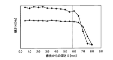
- FIG. 1 It is the schematic which shows the structure of the engine and power transmission device of the vehicle to which this invention was applied. It is a block diagram explaining the principal part of the control system provided in the vehicle in order to control the engine and power transmission device of FIG. It is sectional drawing which shows a part of torque converter and crankshaft including the startering gear of FIG. It is a figure which shows only the startering gear and drive plate which were seen from the IV arrow direction in FIG. It is sectional drawing which shows the VV arrow part cross section of FIG. Of the starter gears, the relationship between the distance from the tip surface of the outer peripheral teeth in the radial direction and the hardness of the starter gear at a position 0.5 mm in the thickness direction from one side surface is shown for each predetermined circumferential position.
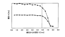
- FIG. 1 shows the relationship between the distance from the tip surface of the outer peripheral teeth in the radial direction and the hardness of the starter gear at a position 0.5 mm in the thickness direction from one side surface.
- FIG. 1 is a schematic diagram showing the configuration of a vehicle engine 10 and a power transmission device 12 to which the present invention is applied.
- the engine 10 and the power transmission device 10 are suitably employed in an FR (front engine / rear drive) type vehicle.
- the output of the engine 10 as a driving power source constituted by the internal combustion engine is transmitted from the crankshaft 14 of the engine 10 through the torque converter 16, the automatic transmission 18, and the propeller shaft 20, respectively. And is distributed from the differential gear device 22 to the left and right drive wheels 24L, 24R.
- the torque converter 16 includes a pump impeller 16p connected to the crankshaft 14 via a disk-shaped drive plate 26, a turbine impeller 16t connected to the input shaft 28 of the automatic transmission 18, and a one-way clutch 30. And a stator impeller 16s that is prevented from rotating in one direction by the rotation of the pump impeller 16p that rotates together with the crankshaft 14, and is circulated in the torque converter 16 by the pump impeller 16p.
- This is a well-known fluid transmission device that is transmitted to the turbine impeller 16t via the.
- the pump impeller 16p is connected to a drive shaft of a mechanical oil pump 32.
- the mechanical oil pump 32 is driven to rotate by the engine 10.
- the drive plate 26 corresponds to a disk-like member that rotates together with the engine in the present invention.
- the automatic transmission 18 includes a transmission mechanism 34 having a plurality of planetary gear units and a plurality of hydraulic engagement devices such as clutches and brakes, and a hydraulic engagement device for switching the engagement state of the hydraulic engagement devices.
- a hydraulic control circuit 36 that controls the supplied hydraulic pressure is a main component, and a rotational speed ratio, that is, a gear ratio between the input shaft 28 and the output shaft 38 is a plurality of gear ratios set in advance according to the traveling state of the vehicle. It is a well-known planetary gear type transmission that can be selectively switched to any one of the following.
- the power transmission device 12 includes the mechanical oil pump 32 and an electric oil pump 40 that is operated by battery power (not shown) regardless of the operation of the engine 10.
- the hydraulic pressure control circuit 36 is supplied with a hydraulic pressure as a source pressure from either the mechanical oil pump 32 or the electric oil pump 40, and the hydraulic pressure control circuit 36 returns the original pressure to the hydraulic pressure engagement circuit. The hydraulic pressure adjusted to is supplied.
- the power transmission device 12 includes an engine start device 42 for starting the engine 10, that is, assisting the operation of the engine 10 until the engine 10 rotates by itself.
- the engine starting device 42 has an annular shape with outer peripheral teeth 44a, has a startering gear 44 fixed to the outer peripheral surface of the drive plate 26, and a pinion gear 46a that can mesh with the outer peripheral teeth 44a.
- a magnet switch 48 for moving the pinion gear 46a between a meshing position where the pinion gear 46a meshes with the starter ring gear 44 and a non-meshing position where the pinion gear 46a is not meshed.
- the starter motor 46 is fixed to an output shaft 46b that can move in the axial direction parallel to the rotation center line C of the starter ring gear 44 and a tip of the output shaft 46b, as indicated by an arrow a in FIG. And a pinion gear 46a.
- the magnet switch 48 is provided so as to be movable in a direction parallel to the output shaft 46a as shown by an arrow b in FIG. 1, and is attracted to the solenoid 48a side when the solenoid 48a is energized. And a movable iron core 48b.
- the pinion gear 46 a When the starter motor 46 is rotationally driven by the starter motor 46, the pinion gear 46 a is energized by the solenoid 48 a to move the movable iron core 48 b toward the solenoid 48 a, and the movable iron core 48 b passes through the lever member 50.
- the output shaft 46b By moving the output shaft 46b toward the startering gear 44 in the axial direction, the output shaft 46b can be moved to a meshing position that meshes with the startering gear 44 as indicated by a broken line in FIG.
- the starter ring gear 44 is rotationally driven by the output torque of the starter motor 46 transmitted via the pinion gear 46a positioned at the meshing position.
- the engine starter 42 configured as described above operates the starter motor 46 at the time of engine start to rotationally drive the crankshaft 14 via the pinion gear 46a and the ring gear 44, so that the rotational speed of the engine 10 is determined in advance. Increase the engine ignition speed to
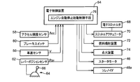
- FIG. 2 is a block diagram illustrating a main part of a control system provided in the vehicle in order to control the engine 10 and the power transmission device 12 of FIG.
- the electronic control unit 54 includes a so-called microcomputer having a CPU, a RAM, a ROM, an input / output interface, etc., for example, and the CPU stores in the ROM in advance using the temporary storage function of the RAM.
- the CPU stores in the ROM in advance using the temporary storage function of the RAM.
- the electronic control unit 54 includes, for example, a vehicle speed signal indicating the vehicle speed V detected by the vehicle speed sensor 56, an accelerator pedal operation amount detected by the accelerator opening sensor 58, that is, an accelerator opening signal indicating the accelerator opening Acc, a brake A brake operation signal indicating whether or not the brake pedal is depressed detected by the switch 60, an operation position signal indicating the operation position P SH of the shift lever 66 of the shift operation device 64 detected by the lever position sensor 62, and the like are supplied. .
- the shift operation device 64 to switch the operating state of the automatic transmission 18, and has a shift lever 66 is manually operated to a plurality of operating positions P SH predetermined by the driver.
- the shift lever 66 is a parking position for locking the output shaft 38 of the automatic transmission 18 while blocking the power transmission path in the automatic transmission 18, and reverse travel for switching the automatic transmission 18 to the reverse gear stage. Any one of a position, a neutral position for interrupting the power transmission path in the automatic transmission 18, and a forward traveling position for automatically shifting the automatic transmission 18 within the range of the D range including a plurality of forward gears. It is provided so that it can be operated.
- an engine output control command signal for output control of the engine 10 for example, a throttle signal for driving the throttle actuator 70 for controlling the opening and closing of the electronic throttle valve 68, a fuel injection device 72
- a fuel injection signal for controlling the amount of fuel injected from the engine, an ignition timing signal for controlling the ignition timing of the engine 10 by the ignition device 74, and the like are output.
- the electronic control unit 54 also controls a signal for controlling the hydraulic control circuit 36 to switch the gear position of the automatic transmission 18, a signal for rotationally driving the starter motor 46, and a pinion gear 46a of the starter motor 46 as a starter gear.
- a signal for energizing the solenoid 48a of the magnet switch 48 in order to engage with the magnet 44 is output.
- the engine automatic stop / start control means 76 among the control functions of the electronic control unit 54 will be described.
- the engine automatic stop / start control means 76 automatically stops the engine 10 temporarily when the vehicle travels stopped, and restarts the engine 10 by rotationally driving the starter gear 44 by the starter motor 46 of the engine starter 42 when the vehicle travels start.
- the engine automatic stop start control to start is performed.
- the engine automatic stop / start control is also referred to as eco-run control (economy running control) or idle stop control.
- the engine automatic stop / start control means 76 turns off the engine 10 when a predetermined engine stop condition is satisfied in order to improve fuel consumption, reduce exhaust gas, reduce noise, etc. when the vehicle stops at an intersection or the like.
- a control for closing the electronic throttle valve 68 by the throttle actuator 70, a control for stopping the fuel supply by the fuel injection device 72, and the like are executed.
- the engine automatic stop / start control means 76 starts the engine 10 by the engine starter 46 when a predetermined engine start condition is satisfied.
- the predetermined engine stop condition in the present embodiment is a forward traveling state in which the automatic transmission 18 is automatically shifted within the range of the D range, the accelerator opening Acc is zero, and the foot brake is operated. And the vehicle speed V is zero.
- the predetermined engine start condition in the present embodiment is a case where an operation intended to start the vehicle is performed by the driver, and the foot brake is not operated or the accelerator pedal is operated. It is operated and the accelerator opening Acc exceeds zero.
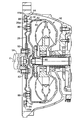
- FIG. 3 is a cross-sectional view showing a part of the torque converter 16 and the crankshaft 14 including the startering gear 44.
- FIG. 4 is a diagram showing only the startering gear 44 and the drive plate 26 as seen from the direction of arrow IV in FIG. 5 is a cross-sectional view showing a cross section taken along the line V-V in FIG.
- the drive plate 26 has a center hole 78 formed concentrically with the rotation center line C in a protrusion 80 formed on one end surface of the crankshaft 14 and concentrically with the rotation center line C.
- crankshaft 14 is fastened by a plurality of bolts 82.
- the outer periphery of the drive plate 26 is fastened to the cover 84 of the torque converter 16 by a plurality of bolts 86.
- a short cylindrical portion 26 a is provided on the outer peripheral portion of the drive plate 26 so as to protrude from the side opposite to the torque converter 16.
- the drive plate 26 and the cover 84 are rotating members that are rotatably provided with the crankshaft 14.
- the starter gear 44 is formed by, for example, forming an annular member by bending a rod-shaped drawing material in an annular shape and welding the end surfaces thereof to face each other.
- a plurality of outer peripheral teeth 44a parallel to the rotation center line C are formed by using a cutting tool such as the like, and the outer peripheral teeth are subjected to induction hardening to be manufactured.
- the startering gear 44 manufactured as described above is plurally connected to the drive plate 26 while being fitted to the outer peripheral surface of the short cylindrical portion 26 a of the drive plate 26.
- the location is fixed by, for example, MIG welding (MIG (metal alloy gas) welding).
- the rotation center line C is formed on the other side surface 90 opposite to the one side surface 88 facing the pinion gear 46a positioned in the non-engagement position in a direction parallel to the rotation axis C.
- Welding with the drive plate 26 is performed at four positions at equal intervals in the circumferential direction. 3 to 5 show a weld bead 92 formed in a welded portion between the startering gear 44 and the drive plate 26.
- the startering gear 44 includes a plurality of welds, that is, weld beads, between the inner peripheral surface and the tooth surface of the outer peripheral teeth 44a between the startering gear 44 and the drive plate 26.
- a plurality of (four in this embodiment) circumferential grooves 94 are formed on the outer peripheral side of 92 so as to have a circumferential length longer than those of the weld beads 92.
- the plurality of circumferential grooves 94 function as heat resistance portions that suppress conduction of heat during welding to the outer peripheral teeth 44a when the startering gear 44 and the drive plate 26 are welded.
- the other side surface 90 is formed in the circumferential direction.
- FIG. 6 shows the tip surface of the outer peripheral teeth 44a at a position 0.5 mm inside the thickness direction from one side surface 88 of the startering gear 44 configured as described above, as shown in FIG.
- FIG. 6 is a diagram showing a relationship between a distance S [mm] radially inward from the head and a hardness (Vickers hardness) H [Hv] of a startering gear 44 at two positions in the circumferential direction.
- the outer peripheral teeth 44a shown in the VV arrow section of FIG. 4 are indicated by solid lines in FIG. 6, and the outer peripheral teeth 44a indicated by arrows d in FIG. 4 are indicated by one-dot chain lines in FIG. Yes.
- the relationship shown in FIG. 6 is obtained experimentally.
- FIG. 11 is different from the startering gear 44 of the present embodiment only in that a plurality of circumferential grooves 94 are not provided, the conventional startering gear differs from the side 88 in the thickness direction.
- the relationship between the distance S [mm] radially inward from the tip surface of the outer peripheral teeth 44a and the hardness (Vickers hardness) H [Hv] of the startering gear 44 at the position on the inner side of 0.5 [mm] ⁇ It is a figure shown about two positions of a direction, respectively.
- the outer peripheral tooth 44a on the outer peripheral side of the welded portion between the conventional startering gear and the drive plate 26 is indicated by a solid line in FIG. 11, and the outer peripheral tooth 44a not located on the outer peripheral side of the welded portion is shown in FIG. 11 is indicated by a one-dot chain line. Note that the relationship of FIG. 11 is obtained experimentally.
- the hardness H of the outer peripheral teeth 44a located on the outer peripheral side of the welded portion with the drive plate 26 is compared with the hardness H of the outer peripheral teeth 44a not located on the outer peripheral side of the welded portion.
- the smaller is the same for both the startering gear 44 and the conventional startering gear. This is because heat at the time of welding with the drive plate 26 is conducted to the outer peripheral teeth 44a located on the outer peripheral side of the welded portion, so that the outer peripheral teeth 44a located on the outer peripheral side of the welded portion are annealed. It is thought to be caused by However, the startering gear of the present embodiment shown in the solid line in FIG.
- the hardness H of the outer peripheral teeth 44a located on the outer peripheral side of the welded portion between the startering gear 44 of this embodiment and the drive plate 26 is larger than that of the conventional one. Since there is a circumferential groove 94 between the welded portion and the outer peripheral teeth 44a, a conduction path when heat at the time of welding with the drive plate 26 is conducted to the outer peripheral teeth 44a is a path that bypasses the circumferential groove 94. In addition to becoming longer, it is considered that the amount of heat conducted to the outer peripheral teeth 44a is reduced because the heat radiation area is larger than that without the circumferential groove 94.
- a plurality of welds that is, outer peripheral sides of the weld beads 92, function as a heat resistance unit that suppresses conduction of heat during welding with the drive plate 26 to the outer peripheral teeth 44 a, and are more peripheral than the weld beads 92. Since the plurality of circumferential grooves 94 are formed in the circumferential direction on the other side surface 90 so as to increase the length in the direction, the startering gear 44 in which the hardness of the outer peripheral teeth 44a is increased by induction hardening is provided.
- the starter gear 44 automatically stops the engine 10 temporarily when the vehicle travel is stopped, and the starter motor 44 of the engine starter 42 causes the starter gear 44 to be stopped when the vehicle travel is started. Since it is provided in the engine starter 42 including the engine automatic stop / start control means 76 that restarts the engine 10 by rotational driving, the engine automatic stop / start control is executed, so that the control is not executed. Thus, even when the number of engine starts is greatly increased and the durability of the startering gear 44 is further required, a plurality of circumferential grooves 94 are formed on the other side surface 90 of the startering gear 44 in a relatively simple manner. The durability of the outer peripheral teeth 44a of the startering gear 44 can be changed by simply making changes. It is possible to increase.
- FIG. 7 is a view showing a startering gear 100 and a drive plate 26 according to another embodiment of the present invention, and corresponds to FIG. 4 of the first embodiment.
- the startering gear 100 is different from the startering gear 44 of the first embodiment in that it replaces the circumferential groove 94 and starts between the inner peripheral surface of the startering gear 100 and the tooth surface of the outer peripheral teeth 44 a.
- a plurality of welded portions between the ring gear 100 and the drive plate 26, that is, the outer peripheral side of the weld bead 92 has an annular groove 102 continuously formed on the other side surface 90 over the entire circumference. It is a configuration.
- the cross-sectional shape of the annular groove 102 is the same as the cross-sectional shape of the circumferential groove 94 shown in FIG.
- it functions as a heat resistance portion that suppresses conduction of heat during welding with the drive plate 26 to the outer peripheral teeth 44 a, and the annular groove 102 formed continuously on the other side surface 90 over the entire circumference. Therefore, when the startering gear 44 in which the hardness of the outer peripheral teeth 44a is increased by induction hardening is welded in a state of being fitted to the outer peripheral surface of the drive plate 26, the heat at the time of welding is increased.
- the annular groove 102 formed continuously over the entire circumference is easier to process than the circumferential groove 94 formed in a part of the circumferential direction. Therefore, it is possible to reduce the manufacturing cost of the startering gear 100 and contribute to the weight reduction of the parts.
- the circumferential groove 94 coincides with a predetermined circumferential position where the startering gear 44 and the drive plate 26 are welded when the startering gear 44 is fitted to the outer peripheral surface of the drive plate 26.
- FIG. 8 is a view showing a startering gear 110 and a drive plate 26 according to another embodiment of the present invention, and corresponds to FIG. 5 of the first embodiment.
- the startering gear 110 is different from the startering gear 44 of the first embodiment in that it replaces the circumferential groove 94 and starts between the inner peripheral surface of the startering gear 110 and the tooth surface of the outer peripheral teeth 44a.
- the configuration is the same except that a plurality of (four in this embodiment) through holes 112 are formed.
- the circumferential position where the through hole 112 is formed is the same as the circumferential position of the circumferential groove 94 shown in FIG.
- the startering gear 110 of the present embodiment among the inner peripheral surface of the startering gear 110 and the tooth surface of the outer peripheral teeth 44a, a plurality of welds between the drive plate 26, that is, the outer peripheral side of the weld bead 92. In addition, it functions as a heat resistance portion that suppresses conduction of heat at the time of welding with the drive plate 26 to the outer peripheral teeth 44a, and is formed by penetrating from one side surface 88 to the other side surface 90.
- the startering gear 44 in which the hardness of the outer peripheral teeth 44a is increased by induction hardening is welded while being fitted to the outer peripheral surface of the drive plate 26, the welding is performed. Since heat at the time is suppressed from being transmitted to the outer peripheral teeth 44a and the outer peripheral teeth 44a are suppressed from being annealed, Hardness of the outer tooth 44a in the vicinity of the weld by contact can be prevented from being lowered.
- FIG. 9 is a view showing a startering gear 120 and a drive plate 122 according to another embodiment of the present invention, and corresponds to FIG. 3 of the first embodiment.
- a short cylindrical portion 122 a that protrudes toward the torque converter 16 is provided on the outer peripheral portion of the drive plate 122.
- the starter gear 120 is fixed to a plurality of locations with the drive plate 122 by, for example, MIG welding (MIG (metal-inert-gas) welding) while being fitted to the outer peripheral surface of the short cylindrical portion 122a of the drive plate 122.
- MIG welding metal-inert-gas
- one side surface 124 facing the pinion gear 46a positioned at the non-engagement position in a direction parallel to the rotation axis C is 4 equally spaced in the circumferential direction around the rotation center line C. The place is welded to the drive plate 122.
- the pinion gear 46a is moved to a meshing position where the magnet switch 48 meshes with the starter ring gear 120.
- the startering gear 120 is not rotationally driven by 46, the startering gear 120 is moved to a non-meshing position where it does not mesh with the startering gear 120.
- the startering gear 120 has a plurality of welded portions between the startering gear 120 and the drive plate 122, that is, an outer peripheral side of the weld bead 92 between the inner peripheral surface and the tooth surface of the outer peripheral tooth 120 a.
- a plurality of (four in this embodiment) circumferential grooves 126 are formed so as to have a longer circumferential length.
- the plurality of circumferential grooves 126 function as heat resistance portions that suppress conduction of heat during welding to the outer peripheral teeth 120a when the startering gear 120 and the drive plate 122 are welded.
- the pinion gear 46a positioned at the non-meshing position is circumferentially formed on one side surface 124 facing the pinion gear 46a in a direction parallel to the rotational axis C.
- the pinion gear 46a is moved to a meshing position that meshes with the startering gear 120 when the starter motor 120 is rotationally driven by the starter motor 46, as in the first embodiment.
- the starter motor 46 is not rotationally driven by the starter motor 46, it is moved to a non-meshing position where it does not mesh with the startering gear 120, and is positioned at the non-meshing position on both sides of the starter gear 120.
- One side surface 124 facing the pinion gear 46a in a direction parallel to the rotational axis C is welded to the drive plate 122, and a circumferential groove 126 as a heat resistance portion is provided on one side surface 124 thereof.
- Startering gear 1 Among the zero outer peripheral teeth 120a, the startering gear 120 and the drive plate 122 are particularly arranged on the one side 124 side that comes into contact with the pinion gear 46a when the pinion gear 46a is moved from the non-meshing position to the meshing position. Heat conduction during welding is suppressed, so that a decrease in the hardness of the outer side teeth 120a of the startering gear 120 on the one side surface 124 side that is particularly required to be hard is suppressed. be able to.
- the startering gear 44 (100, 110, 120) has a peripheral portion on the outer peripheral side of the welded portion as a heat resistance portion that suppresses heat conduction during welding with the drive plate 26 (122) to the outer peripheral teeth 44a.
- Any one of the directional groove 94 (126), the annular groove 102, and the through hole 112 is provided.
- a member made of a material having low thermal conductivity such as a heat-resistant resin is provided on the outer peripheral side of the welded portion. May be.
- a metal inner annular member, a heat resistant resin intermediate annular member, and a metal outer annular member, which are formed in three layers in the radial direction, are joined to each other, and a starter motor is attached to the outer circumferential surface of the outer annular member.
- the startering gear may be manufactured by forming outer peripheral teeth that mesh with the pinion gear. If it does in this way, it will suppress by the intermediate
- Example 1 it forms in the circumferential direction in the outer peripheral side of a welding part as a heat resistance part which suppresses the heat
- the groove shape is not limited to this.
- a straight groove 132 formed in a tangential direction on the outer peripheral side of the welded portion may be provided on the side surface of the startering gear 130 as the heat resistance portion. .
- the startering gear 44 (100, 110, 120) and the drive plate 26 (122) are joined by MIG welding (MIG (metal-inert-gas) welding), but are joined by other welding such as laser welding. May be.
- MIG welding metal-inert-gas welding
- the startering gear 44 (100, 110, 120) was welded to the drive plate 26 (122) at four equal intervals in the circumferential direction around the rotation center line C. It does not have to be, and it does not have to be four places. For example, 6 or 12 locations may be welded.
- the startering gear 44 (100, 110, 120) is welded to the drive plate 26 (122), but is welded to other members that rotate together with the crankshaft 14 of the engine 10, such as the cover 84 of the torque converter 16, for example. May be.
- circumferential groove 94 (126) and the through hole 112 are arranged on the outer peripheral side of the plurality of welded portions between the startering gear 44 (110) and the drive plate 26, that is, on the outer peripheral side of the weld bead 92.
- the length is formed to be long, the circumferential length is not necessarily longer than the weld bead 92.
- circumferential groove 94 (126) and the through hole 112 are not necessarily provided on the outer peripheral side of one weld bead 92.
- a plurality may be provided such that they are overlapped in the radial direction or arranged in the circumferential direction.
- circumferential groove 94 (126) and the annular groove 102 are not necessarily provided only on one side surface, and may be provided on both side surfaces.
- the engine starter 42 is of a type in which the pinion gear 46a of the starter motor 46 is engaged with the startering gear 44 (100, 110, 120) only when the engine is started.
- the starter motor 46 and the startering gear 44 are used.
- Other types, such as those employing a constant meshing ring gear in which a constant meshing clutch is provided between them, may be used.
- the startering gear 44 (100, 110, 120) is provided in the power transmission device 12 including the automatic transmission 18 which is a planetary gear type transmission.
- the startering gear 44 (100, 110, 120) is always equipped with a continuously variable transmission or an automatic clutch. You may provide in a power transmission device provided with other transmissions, such as a meshing type transmission.
- Engine 26 Drive plate (disk-shaped member) 44: Starter gear (starter gear for vehicle) 44a: outer peripheral teeth 46: starter motor 46a: pinion gears 88, 124: one side 90: the other side 92: weld bead (welded part) 94, 126: circumferential groove (thermal resistance part) 102: Annular groove (heat resistance part) 112: Through hole (thermal resistance part) C: Center of rotation
Landscapes
- Engineering & Computer Science (AREA)
- Mechanical Engineering (AREA)
- General Engineering & Computer Science (AREA)
- Physics & Mathematics (AREA)
- Plasma & Fusion (AREA)
- Optics & Photonics (AREA)
- Chemical & Material Sciences (AREA)
- Combustion & Propulsion (AREA)
- Gears, Cams (AREA)
- Connection Of Motors, Electrical Generators, Mechanical Devices, And The Like (AREA)
Abstract
Description
26:ドライブプレート(円板状部材)
44:スタータリングギヤ(車両用スタータリングギヤ)
44a:外周歯
46:スタータモータ
46a:ピニオンギヤ
88,124:一方の側面
90:他方の側面
92:溶接ビード(溶接部)
94,126:周方向溝(熱抵抗部)
102:環状溝(熱抵抗部)
112:貫通穴(熱抵抗部)
C:回転中心線
Claims (6)
- 外周歯を有して円環状を成し、エンジンと共に回転する円板状部材の外周面に嵌合された状態で該円板状部材との間で複数箇所が溶接され、前記エンジンを始動するために、前記外周歯と噛合可能なピニオンギヤを有するスタータモータにより回転駆動される車両用スタータリングギヤであって、
該車両用スタータリングギヤの内周面と前記外周歯の歯面との間のうち、少なくとも該車両用スタータリングギヤと前記円板状部材との間の溶接部の外周側に、該溶接部の溶接時の熱が前記外周歯へ伝導することを抑制する熱抵抗部を備えていることを特徴とする車両用スタータリングギヤ。 - 前記熱抵抗部は、前記車両用スタータリングギヤの側面に周方向に形成された周方向溝または接線方向に形成された直線溝であることを特徴とする請求項1の車両用スタータリングギヤ。
- 前記熱抵抗部は、前記車両用スタータリングギヤの側面に全周にわたって連続して形成された環状溝であることを特徴とする請求項1の車両用スタータリングギヤ。
- 前記熱抵抗部は、前記車両用スタータリングギヤの一方の側面から他方の側面に向けて貫通して形成された貫通穴であることを特徴とする請求項1の車両用スタータリングギヤ。
- 前記ピニオンギヤは、前記車両用スタータリングギヤに噛み合う噛合位置と該車両用スタータリングギヤに噛み合わない非噛合位置との間で該車両用スタータリングギヤの回転中心線に平行な方向に移動可能に設けられ、前記スタータモータにより該車両用スタータリングギヤが回転駆動される場合には前記噛合位置に移動させられ、該スタータモータにより該車両用スタータリングギヤが回転駆動されない場合には前記非噛合位置に移動させられるものであり、
前記熱抵抗部は、前記非噛合位置に位置させられた前記ピニオンギヤに対して前記回転中心線に平行な方向において対向する前記車両用スタータリングギヤの一方の側面に前記円板状部材との溶接が施される場合には、該一方の側面に設けられることを特徴とする請求項2または3の車両用スタータリングギヤ。 - 前記車両用スタータリングギヤは、車両走行停止時には前記エンジンが一時的に自動停止されると共に車両走行開始時には該エンジンが再始動されるエンジン自動停止始動制御の実行時において、該エンジンを再始動するために前記スタータモータにより回転駆動されるものであることを特徴とする請求項1乃至5のいずれか1の車両用スタータリングギヤ。
Priority Applications (3)
| Application Number | Priority Date | Filing Date | Title |
|---|---|---|---|
| CN2010800671561A CN103026100A (zh) | 2010-06-01 | 2010-08-09 | 车辆用起动机齿圈 |
| US13/701,037 US20130061716A1 (en) | 2010-06-01 | 2010-08-09 | Vehicular starter ring gear |
| DE112010005628.5T DE112010005628T8 (de) | 2010-06-01 | 2010-08-09 | Fahrzeug-Starterzahnkranz |
Applications Claiming Priority (2)
| Application Number | Priority Date | Filing Date | Title |
|---|---|---|---|
| JP2010-126236 | 2010-06-01 | ||
| JP2010126236A JP5363422B2 (ja) | 2010-06-01 | 2010-06-01 | 車両用スタータリングギヤ |
Publications (1)
| Publication Number | Publication Date |
|---|---|
| WO2011151932A1 true WO2011151932A1 (ja) | 2011-12-08 |
Family
ID=45066327
Family Applications (1)
| Application Number | Title | Priority Date | Filing Date |
|---|---|---|---|
| PCT/JP2010/063509 Ceased WO2011151932A1 (ja) | 2010-06-01 | 2010-08-09 | 車両用スタータリングギヤ |
Country Status (5)
| Country | Link |
|---|---|
| US (1) | US20130061716A1 (ja) |
| JP (1) | JP5363422B2 (ja) |
| CN (1) | CN103026100A (ja) |
| DE (1) | DE112010005628T8 (ja) |
| WO (1) | WO2011151932A1 (ja) |
Cited By (2)
| Publication number | Priority date | Publication date | Assignee | Title |
|---|---|---|---|---|
| US20140157929A1 (en) * | 2012-12-12 | 2014-06-12 | Guobin Yin | Flexplates and method for capacitor discharge welding of flexplates |
| CN106471284A (zh) * | 2014-07-25 | 2017-03-01 | 爱信艾达株式会社 | 传动板及其制造方法 |
Families Citing this family (8)
| Publication number | Priority date | Publication date | Assignee | Title |
|---|---|---|---|---|
| DE102010023728A1 (de) * | 2010-06-14 | 2011-12-15 | Liebherr-Verzahntechnik Gmbh | Verfahren zum Herstellen einer Mehrzahl von identischen Zahnrädern mittles abspanender Bearbeitung |
| JP5883669B2 (ja) * | 2012-02-07 | 2016-03-15 | 自動車部品工業株式会社 | スタータドライブギヤ |
| JP6142369B2 (ja) | 2013-02-27 | 2017-06-07 | 浙江三花制冷集団有限公司 | 電子膨張弁およびそれのための接続アセンブリ |
| JP6523631B2 (ja) * | 2014-08-12 | 2019-06-05 | Ntn株式会社 | 歯車およびこれを備えた電動アクチュエータ |
| JP6207544B2 (ja) * | 2015-04-28 | 2017-10-04 | 株式会社平安製作所 | ドライブプレートとその製造方法 |
| CN105673288B (zh) * | 2015-12-14 | 2017-09-19 | 湖南罗佑发动机部件有限公司 | 一种发动机起动部结构 |
| US11536236B2 (en) | 2020-05-31 | 2022-12-27 | Borgwarner Inc. | Permanently engaged starter system |
| US11231004B2 (en) * | 2020-05-31 | 2022-01-25 | Borg Warner Inc. | Permanently engaged starter system |
Citations (5)
| Publication number | Priority date | Publication date | Assignee | Title |
|---|---|---|---|---|
| JPS63184259U (ja) * | 1987-05-20 | 1988-11-28 | ||
| JPH0399788A (ja) * | 1989-09-13 | 1991-04-24 | Yutaka Giken Co Ltd | ギヤ及びその製造方法 |
| JPH0415352A (ja) * | 1990-05-09 | 1992-01-20 | Mazda Motor Corp | エンジンのスタータリングギア固定構造 |
| JPH05208280A (ja) * | 1992-01-30 | 1993-08-20 | Aisin Seiki Co Ltd | 環状部材を備えた円盤組立体及びその溶接方法 |
| JPH10231918A (ja) * | 1997-02-21 | 1998-09-02 | Isuzu Motors Ltd | 歯 車 |
Family Cites Families (19)
| Publication number | Priority date | Publication date | Assignee | Title |
|---|---|---|---|---|
| JPS61116071A (ja) * | 1984-11-08 | 1986-06-03 | Nippon Denso Co Ltd | スタ−タ |
| JPS63184259A (ja) * | 1987-01-26 | 1988-07-29 | Mitsubishi Electric Corp | マイクロ波放電光源装置 |
| JP2542093B2 (ja) * | 1989-11-21 | 1996-10-09 | 三菱電機株式会社 | 遊星歯車式減速スタ―タ装置 |
| JPH08103872A (ja) * | 1994-10-04 | 1996-04-23 | Nippon Steel Corp | 耐摩耗性複合管の溶接方法 |
| JP3072714B2 (ja) * | 1995-09-04 | 2000-08-07 | 株式会社デンソー | 減速機構付スタータ |
| DE69700196T2 (de) * | 1996-02-16 | 1999-12-16 | Denso Corp., Kariya | Anlasser mit Planetuntersetzungsgetriebe |
| JP3620950B2 (ja) | 1997-06-23 | 2005-02-16 | ジヤトコ株式会社 | オートマチックトランスアクスル |
| FR2799254B1 (fr) * | 1999-09-30 | 2003-05-30 | Defontaine | Systeme de liaison d'une couronne dentee de demarreur sur un support lie a l'arbre de sortie d'un moteur thermique |
| DE20109743U1 (de) * | 2001-06-11 | 2001-08-09 | Andreas Stihl AG & Co., 71336 Waiblingen | Startvorrichtung für eine Brennkraftmaschine |
| DE102005060395A1 (de) * | 2004-12-17 | 2006-07-06 | Denso Corp., Kariya | Motoranlasser mit einem Drehmomentabsorber |
| JP4449852B2 (ja) * | 2005-07-29 | 2010-04-14 | トヨタ自動車株式会社 | 内燃機関始動回転力伝達機構 |
| DE112006003545B4 (de) * | 2005-12-28 | 2018-05-17 | Mitsuba Corp. | Motor-Anlasser |
| JP4462213B2 (ja) * | 2006-03-16 | 2010-05-12 | トヨタ自動車株式会社 | 内燃機関始動回転力伝達機構潤滑構造 |
| JP2007309209A (ja) * | 2006-05-18 | 2007-11-29 | Yamaha Motor Co Ltd | エンジンの始動装置 |
| JP4179349B2 (ja) * | 2006-06-23 | 2008-11-12 | トヨタ自動車株式会社 | リングギヤ、内燃機関始動回転力伝達機構及びリングギヤ製造方法 |
| EP1908954A1 (en) * | 2006-09-29 | 2008-04-09 | Ford Global Technologies, LLC. | Starter arrangement for an internal combustion engine |
| EP2113655A4 (en) * | 2006-12-26 | 2011-07-20 | Mitsuba Corp | STARTER APPARATUS |
| JP2009052448A (ja) * | 2007-08-24 | 2009-03-12 | Denso Corp | 中間歯車付スタータ |
| JP5471572B2 (ja) * | 2009-04-07 | 2014-04-16 | 株式会社デンソー | エンジン始動装置 |
-
2010
- 2010-06-01 JP JP2010126236A patent/JP5363422B2/ja not_active Expired - Fee Related
- 2010-08-09 CN CN2010800671561A patent/CN103026100A/zh active Pending
- 2010-08-09 US US13/701,037 patent/US20130061716A1/en not_active Abandoned
- 2010-08-09 WO PCT/JP2010/063509 patent/WO2011151932A1/ja not_active Ceased
- 2010-08-09 DE DE112010005628.5T patent/DE112010005628T8/de not_active Ceased
Patent Citations (5)
| Publication number | Priority date | Publication date | Assignee | Title |
|---|---|---|---|---|
| JPS63184259U (ja) * | 1987-05-20 | 1988-11-28 | ||
| JPH0399788A (ja) * | 1989-09-13 | 1991-04-24 | Yutaka Giken Co Ltd | ギヤ及びその製造方法 |
| JPH0415352A (ja) * | 1990-05-09 | 1992-01-20 | Mazda Motor Corp | エンジンのスタータリングギア固定構造 |
| JPH05208280A (ja) * | 1992-01-30 | 1993-08-20 | Aisin Seiki Co Ltd | 環状部材を備えた円盤組立体及びその溶接方法 |
| JPH10231918A (ja) * | 1997-02-21 | 1998-09-02 | Isuzu Motors Ltd | 歯 車 |
Cited By (5)
| Publication number | Priority date | Publication date | Assignee | Title |
|---|---|---|---|---|
| US20140157929A1 (en) * | 2012-12-12 | 2014-06-12 | Guobin Yin | Flexplates and method for capacitor discharge welding of flexplates |
| US9982748B2 (en) * | 2012-12-12 | 2018-05-29 | Magna International | Flexplates and method for capacitor discharge welding of flexplates |
| US20180266517A1 (en) * | 2012-12-12 | 2018-09-20 | Magna International | Flexplates and method for capacitor discharge welding of flexplates |
| US10975931B2 (en) | 2012-12-12 | 2021-04-13 | Magna International | Flexplates and method for capacitor discharge welding of flexplates |
| CN106471284A (zh) * | 2014-07-25 | 2017-03-01 | 爱信艾达株式会社 | 传动板及其制造方法 |
Also Published As
| Publication number | Publication date |
|---|---|
| US20130061716A1 (en) | 2013-03-14 |
| CN103026100A (zh) | 2013-04-03 |
| JP5363422B2 (ja) | 2013-12-11 |
| DE112010005628T5 (de) | 2013-04-04 |
| JP2011252538A (ja) | 2011-12-15 |
| DE112010005628T8 (de) | 2014-01-23 |
Similar Documents
| Publication | Publication Date | Title |
|---|---|---|
| JP5363422B2 (ja) | 車両用スタータリングギヤ | |
| JP4752089B2 (ja) | ベルト式無段変速機 | |
| JP5316724B2 (ja) | 車両用駆動装置 | |
| US20020094899A1 (en) | Transmission unit | |
| EP2899431B1 (en) | Control apparatus for vehicle | |
| JP5731884B2 (ja) | 車両の動力伝達制御装置 | |
| JP2016044612A (ja) | 車両の制御装置 | |
| JP2009174707A (ja) | 自動変速機 | |
| JP2017101745A (ja) | 動力伝達装置の制御装置 | |
| JP6699937B2 (ja) | 車両用制御装置 | |
| JP6794015B2 (ja) | 車両用制御装置 | |
| JP6657818B2 (ja) | 車両制御装置 | |
| WO2009081919A1 (ja) | 自動変速機 | |
| JP6307486B2 (ja) | 車両の制御装置 | |
| JP5883669B2 (ja) | スタータドライブギヤ | |
| JP7330628B2 (ja) | 車両用制御装置 | |
| JP5367445B2 (ja) | 車両の動力伝達制御装置 | |
| JP4909118B2 (ja) | 自動変速機の変速判断装置、変速判断方法、その方法を実現させるプログラムおよびそのプログラムを記録した記録媒体 | |
| JP5774961B2 (ja) | 車両用駆動装置 | |
| JP2014152822A (ja) | 変速機のギヤ締結装置 | |
| JP2012172822A (ja) | 車両用駆動装置 | |
| JP6823617B2 (ja) | 変速機の油圧制御装置及び油圧制御方法 | |
| JP5774962B2 (ja) | 車両用駆動装置 | |
| JP2017161056A (ja) | 動力伝達装置の制御装置 | |
| JP6685787B2 (ja) | 自動変速装置 |
Legal Events
| Date | Code | Title | Description |
|---|---|---|---|
| WWE | Wipo information: entry into national phase |
Ref document number: 201080067156.1 Country of ref document: CN |
|
| 121 | Ep: the epo has been informed by wipo that ep was designated in this application |
Ref document number: 10852536 Country of ref document: EP Kind code of ref document: A1 |
|
| WWE | Wipo information: entry into national phase |
Ref document number: 13701037 Country of ref document: US |
|
| WWE | Wipo information: entry into national phase |
Ref document number: 112010005628 Country of ref document: DE Ref document number: 1120100056285 Country of ref document: DE |
|
| 122 | Ep: pct application non-entry in european phase |
Ref document number: 10852536 Country of ref document: EP Kind code of ref document: A1 |