WO2011145232A1 - ワイヤーハーネスの保護構造 - Google Patents
ワイヤーハーネスの保護構造 Download PDFInfo
- Publication number
- WO2011145232A1 WO2011145232A1 PCT/JP2010/068279 JP2010068279W WO2011145232A1 WO 2011145232 A1 WO2011145232 A1 WO 2011145232A1 JP 2010068279 W JP2010068279 W JP 2010068279W WO 2011145232 A1 WO2011145232 A1 WO 2011145232A1
- Authority
- WO
- WIPO (PCT)
- Prior art keywords
- protective
- wire harness
- protection
- nonwoven fabric
- peripheral surface
- Prior art date
- Legal status (The legal status is an assumption and is not a legal conclusion. Google has not performed a legal analysis and makes no representation as to the accuracy of the status listed.)
- Ceased
Links
Images


Classifications
-
- H—ELECTRICITY
- H02—GENERATION; CONVERSION OR DISTRIBUTION OF ELECTRIC POWER
- H02G—INSTALLATION OF ELECTRIC CABLES OR LINES, OR OF COMBINED OPTICAL AND ELECTRIC CABLES OR LINES
- H02G3/00—Installations of electric cables or lines or protective tubing therefor in or on buildings, equivalent structures or vehicles
- H02G3/02—Details
- H02G3/04—Protective tubing or conduits, e.g. cable ladders or cable troughs
- H02G3/0462—Tubings, i.e. having a closed section
- H02G3/0481—Tubings, i.e. having a closed section with a circular cross-section
-
- H—ELECTRICITY
- H02—GENERATION; CONVERSION OR DISTRIBUTION OF ELECTRIC POWER
- H02G—INSTALLATION OF ELECTRIC CABLES OR LINES, OR OF COMBINED OPTICAL AND ELECTRIC CABLES OR LINES
- H02G3/00—Installations of electric cables or lines or protective tubing therefor in or on buildings, equivalent structures or vehicles
- H02G3/02—Details
- H02G3/04—Protective tubing or conduits, e.g. cable ladders or cable troughs
- H02G3/0406—Details thereof
-
- B—PERFORMING OPERATIONS; TRANSPORTING
- B60—VEHICLES IN GENERAL
- B60R—VEHICLES, VEHICLE FITTINGS, OR VEHICLE PARTS, NOT OTHERWISE PROVIDED FOR
- B60R16/00—Electric or fluid circuits specially adapted for vehicles and not otherwise provided for; Arrangement of elements of electric or fluid circuits specially adapted for vehicles and not otherwise provided for
- B60R16/02—Electric or fluid circuits specially adapted for vehicles and not otherwise provided for; Arrangement of elements of electric or fluid circuits specially adapted for vehicles and not otherwise provided for electric constitutive elements
- B60R16/0207—Wire harnesses
-
- B—PERFORMING OPERATIONS; TRANSPORTING
- B60—VEHICLES IN GENERAL
- B60R—VEHICLES, VEHICLE FITTINGS, OR VEHICLE PARTS, NOT OTHERWISE PROVIDED FOR
- B60R16/00—Electric or fluid circuits specially adapted for vehicles and not otherwise provided for; Arrangement of elements of electric or fluid circuits specially adapted for vehicles and not otherwise provided for
- B60R16/02—Electric or fluid circuits specially adapted for vehicles and not otherwise provided for; Arrangement of elements of electric or fluid circuits specially adapted for vehicles and not otherwise provided for electric constitutive elements
- B60R16/0207—Wire harnesses
- B60R16/0215—Protecting, fastening and routing means therefor
-
- H—ELECTRICITY
- H01—ELECTRIC ELEMENTS
- H01B—CABLES; CONDUCTORS; INSULATORS; SELECTION OF MATERIALS FOR THEIR CONDUCTIVE, INSULATING OR DIELECTRIC PROPERTIES
- H01B7/00—Insulated conductors or cables characterised by their form
- H01B7/0045—Cable-harnesses
Definitions
- the present invention relates to a protective structure for an in-vehicle wire harness, and more particularly to water stoppage in the protective structure.
- Patent Document 1 a water-absorbing sheet that can absorb water well while preventing water-absorbing resin particles from leaking to the outside is known.
- Patent Document 2 the technique of ensuring a water stop with a water absorptive nonwoven fabric is also conventionally known (for example, patent document 2).
- an object of the present invention is to provide a wire harness protection structure that can satisfactorily protect the wire harness in a condensation environment.
- a wire harness protection structure is formed as a wire bundle and a tubular body extending in a longitudinal direction of the wire bundle, and the wire is disposed in an inner space of the tubular body.
- a protective part in which a part of the bundle is disposed, and the protective part is formed of a protective material having a base material and a binder material having a melting point lower than that of the base material, and the joint part of the protective part is The binder material on the inner peripheral surface is heated so that the inner peripheral surface opposed to the inner space is harder than the outer peripheral surface of the protective part while being bonded by the binder material cooled and solidified after heating and melting. It is characterized by being cooled and solidified after melting.
- the protective structure of the wire harness according to the second aspect is characterized in that, in the protective structure according to the first aspect, the outer shape of the protective part is formed in a shape according to the arrangement place.
- the binder material on the inner peripheral surface is hardened so that the inner peripheral surface of the protective portion facing the inner space is harder than the outer peripheral surface of the protective portion. It is solidified by heating, melting and cooling. Thereby, the water
- the outer shape of the protection portion can be formed into a shape corresponding to the arrangement location. Therefore, an electric wire bundle can be easily wired with respect to this arrangement location. Therefore, the problem of unnecessarily routing the wire bundle does not occur.
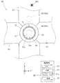
- FIG. 1 is a perspective view showing an example of a configuration of a protective structure for a wire harness according to an embodiment of the present invention.
- FIG. 2 is a side view showing an example of the configuration of a mold used for forming the protective structure.
- FIG. 3 is a side view showing an example of a manufacturing method of the protective structure.
- FIG. 1 is a perspective view showing an example of the configuration of a protective structure 2 for a wire harness 1 according to an embodiment of the present invention.
- the protection structure 2 mainly includes a wire harness 1 and a protection unit 10. 1 and the subsequent drawings have an XYZ orthogonal coordinate system in which the Z-axis direction is a vertical direction and the XY plane is a horizontal plane, as necessary, in order to clarify the directional relationship. .
- the wire harness 1 is a wire bundle in which a plurality of wires 11 are bundled as shown in FIG.
- the wire harness 1 is used, for example, for supplying power to electrical components (not shown) and transmitting / receiving signals.
- the protection unit 10 prevents moisture 7 from entering the wire harness 1 in a dew condensation environment such as the vicinity of the air conditioner duct 5 (see FIG. 1).
- the protection unit 10 is a cylindrical body formed of a nonwoven fabric 12 (protective material), and extends in the longitudinal direction (arrow AR0 direction) of the wire harness 1.
- a part of wire harness 1 is arrange
- the protection unit 10 is formed of, for example, a nonwoven fabric 12.
- the nonwoven fabric 12 mainly has PET (polyethylene terephthalate: base material) and a binder material formed by copolymerization of PET and PEI (polyethylene isophthalate). More specifically, the nonwoven fabric 12 mainly has basic fibers formed in a linear shape by the base material and binder fibers in which a sheath-like binder material is arranged around the basic fibers.
- the melting point (second temperature) of the binder material is 110 to 150 ° C., which is set to be lower than the base material (the melting point of PET: about 250 ° C. (first temperature)).
- FIG. 2 is a side view showing an example of the configuration of a mold 60 used for molding the protective structure 2.
- FIG. 3 is a side view showing an example of a manufacturing method of the protective structure 2. Below, after explaining the structure of the metal mold
- the mold 60 heats and pressurizes the nonwoven fabric 12 to form the nonwoven fabric 12 into the cylindrical protective portion 10.
- the mold 60 mainly includes an upper compression portion 61, a lower compression portion 62, side compression portions 63 and 64, an inner surface forming portion 65, and heaters 66 (66 a and 66 b), have.
- the upper compression part 61 is a pressurizing element that pressurizes the nonwoven fabric 12 arranged around the inner surface forming part 65 from above.
- the contact surface 61a is a curved surface that has an arc shape when viewed from the side and extends in the direction of the arrow AR0.
- the upper compression portion 61 moves relative to the inner surface forming portion 65 (for example, descends in the direction of the arrow AR1), and the nonwoven fabric 12 is sandwiched between the upper compression portion 61 and the inner surface forming portion 65.
- the area near the top is pressurized.
- the lower compression portion 62 is a pressurizing element that pressurizes the nonwoven fabric 12 disposed around the inner surface forming portion 65 from below. As shown in FIG. 2, the lower compression portion 62 is disposed on the opposite side of the upper compression portion 61 with the inner surface forming portion 65 interposed therebetween. Further, the contact surface 62a is a curved surface having an arc shape in a side view, and has the same shape as the contact surface 61a.
- the lower compression portion 62 moves relative to the inner surface forming portion 65 (for example, rises in the direction of the arrow AR2), and the nonwoven fabric 12 is sandwiched between the lower compression portion 62 and the inner surface forming portion 65, thereby The vicinity of the lower part is pressurized.
- Each of the side compression parts 63 and 64 applies pressure to the nonwoven fabric 12 disposed around the inner surface forming part 65 from the side (left side (X axis plus side) and right side (X axis minus side)). Pressure element.
- the side compression portion 64 is disposed on the opposite side of the side compression portion 63 with the inner surface forming portion 65 interposed therebetween.
- each of the contact surface 63a of the side compression part 63 and the contact surface 64a of the side compression part 64 is a curved surface having an arc shape when viewed from the side, and has the same shape as the contact surfaces 61a and 62a.
- the side compression part 63 moves relatively with respect to the inner surface formation part 65 (for example, it progresses to arrow AR3 direction), and is pinched
- the left side is pressurized.
- the side compression part 64 moves relative to the inner surface forming part 65 (for example, proceeds in the direction of the arrow AR4) and is sandwiched between the side compression part 64 and the inner surface forming part 65, whereby the paper surface of the nonwoven fabric 12 is obtained.
- the right side is pressurized.
- the inner surface forming portion 65 is used to form the inner space 10 a in the protection portion 10. As shown in FIG. 2, the inner surface forming portion 65 has a circular shape in a side view, and is a rod-like body that extends in the direction of the arrow AR0. When the protection part 10 is formed, the inner surface forming part 65 is disposed so as to face the first surface 12 a of the nonwoven fabric 12. Then, pressure is applied to the nonwoven fabric 12 from the upper, lower, left, and right sides of the inner surface forming portion 65 by the compression portions 61 to 64, whereby the nonwoven fabric 12 is formed into the cylindrical protection portion 10.
- the heaters 66 are heating elements that heat the nonwoven fabric 12. As shown in FIG. 2, the heater 66 a is embedded in the upper compression portion 61, and the heater 66 b is embedded in the inner surface forming portion 65.
- the heater 66a when the heater 66a is driven, the upper compression part 61 is heated, and the upper part of the nonwoven fabric 12 is mainly heated.
- the heater 66b when the heater 66b is driven, the inner surface forming portion 65 rises in temperature, and mainly the first surface 12a of the nonwoven fabric 12 is heated.
- the control unit 90 realizes, for example, heating control by the heater 66 (66a, 66b), data calculation, and the like.
- the control unit 90 mainly includes a ROM 91, a RAM 92, and a CPU 93.
- the control unit 90 is electrically connected to elements of the mold 60 (for example, heaters 66 (66a, 66b)) via signal lines (not shown).
- ROM (Read Only Memory) 91 is a so-called nonvolatile storage unit, and stores, for example, a program 91a.
- a flash memory that is a readable / writable nonvolatile memory may be used.
- a RAM (Random Access Memory) 92 is a volatile storage unit, and stores, for example, data used in the calculation of the CPU 93.
- a CPU (Central Processing Unit) 93 executes control (for example, heating control of the nonwoven fabric 12) and data calculation according to the program 91a of the ROM 91.
- the nonwoven fabric 12 is arranged so as to surround the inner surface forming portion 65. Thereby, the nonwoven fabric 12 is made into the cylinder which is not compressed and is not joined by the junction part 19 (refer FIG. 3) (refer FIG. 2).
- the compression parts 61 to 64 move relatively in the direction of the inner surface forming part 65.
- the nonwoven fabric 12 is compressed in the radial direction of the cylindrical body by the contact surfaces 61a to 64a of the compression portions 61 to 64.
- the first surface 12a of the nonwoven fabric 12 is formed along the outer periphery of the inner surface forming portion 65, and the second surface 12b of the nonwoven fabric 12 is contacted with the contact surfaces 61a to 64a of the compression portions 61 to 64. Is molded along.
- the 1st surface 12a of the nonwoven fabric 12 becomes an inner peripheral surface of the protection part 10
- the 2nd surface 12b of the nonwoven fabric 12 becomes an outer peripheral surface of the protection part 10.
- the heater 66a of the upper compression unit 61 and the heater 66b of the inner surface forming unit 65 are driven by the control unit 90. Thereby, the nonwoven fabric 12 is heated at a temperature not lower than the melting point (second temperature) of the binder material and lower than the melting point (first temperature) of the base material.
- the joint portion 19 of the protection portion 10 is joined by a binder material that has been cooled and solidified after heating and melting. Further, since the binder material on the first surface 12a is cooled and solidified after being heated and melted, the first surface 12a (inner peripheral surface of the protection portion 10) facing the inner space 10a (see FIG. 1) is the second surface 12b (protection). The outer peripheral surface of the part 10 becomes harder.
- the manufacturing process of the protection structure 2 is complete
- the first surface 12a (inner peripheral surface) of the protective portion 10 facing the inner space 10a is compared with the second surface 12b (outer peripheral surface) of the protective portion 10. Then, the binder material on the first surface 12a is heated and melted and cooled and solidified so as to be hard. That is, on the first surface 12a, the binder material is cooled and solidified after spreading between the base materials, and a water stop function is added to the first surface 12a.
- the wire bundle has been described as a bundle of a plurality of wires 11, but is not limited thereto.
- the electric wire bundle may be constituted by one electric wire 11, and this one electric wire 11 may be inserted into the inner space 10 a of the protection unit 10.
- the nonwoven fabric 12 has been described as being heated by the heaters 66a and 66b, but is not limited thereto.
- the nonwoven fabric 12 may be heated only by the heater 66b.
- the protective part 10 has been described as having a cylindrical shape, but is not limited thereto.
- the shape of the protection unit 10 may be formed into a shape (for example, a shape along the unevenness of the arrangement location) according to the arrangement location of the protection unit 10.
- the wire harness 1 can be easily wired with respect to this arrangement place. Therefore, the problem of routing the wire harness 1 unnecessarily does not occur.
Landscapes
- Engineering & Computer Science (AREA)
- Mechanical Engineering (AREA)
- Architecture (AREA)
- Civil Engineering (AREA)
- Structural Engineering (AREA)
- Details Of Indoor Wiring (AREA)
Abstract
Description
図1は、本発明の実施の形態におけるワイヤーハーネス1の保護構造2の構成の一例を示す斜視図である。図1に示すように、保護構造2は、主として、ワイヤーハーネス1と、保護部10と、を備えている。なお、図1および以降の各図には、それらの方向関係を明確にすべく必要に応じて適宜、Z軸方向を鉛直方向とし、XY平面を水平面とするXYZ直交座標系が付されている。
図2は、保護構造2の成形に用いられる金型60の構成の一例を示す側面図である。また、図3は、保護構造2の製造方法の一例を示す側面図である。以下では、まず、金型60の構成を説明した後、保護構造2の製造方法を説明する。
ここでは、金型60のハードウェア構成について説明する。金型60は、不織布12を加熱および加圧することによって、不織布12を筒状の保護部10に成形する。図2に示すように、金型60は、主として、上方圧縮部61と、下方圧縮部62と、側方圧縮部63、64と、内面形成部65と、ヒータ66(66a、66b)と、を有している。
ここでは、図2および図3を参照しつつ、金型60を用いた保護構造2の製造方法について説明する。
以上のように、本実施の形態の保護構造2において、内側空間10aと対向する保護部10の第1面12a(内周面)が、保護部10の第2面12b(外周面)と比較して硬くなるように、第1面12aにおけるバインダ材が、加熱溶融および冷却凝固している。すなわち、第1面12aにおいて、バインダ材は、基材の間に広がった後に冷却凝固しており、第1面12aには、止水機能が付加されている。
以上、本発明の実施の形態について説明してきたが、本発明は上記実施の形態に限定されるものではなく様々な変形が可能である。
2 保護構造
7 水分
10 保護部
10a 内側空間
11 電線
12 不織布
12a 第1面(内周面)
12b 第2面(外周面)
19 接合部
60 金型
61 上方圧縮部
61a、62a、63a、64a 接触面
62 下方圧縮部
63 側方圧縮部
64 側方圧縮部
65 内面形成部
66(66a、66b) ヒータ
90 制御部
Claims (2)
- (a) 電線束と、
(b) 前記電線束の長手方向に延伸する筒体として成形されるとともに、前記筒体の内側空間に前記電線束の一部が配置された保護部と、
を備え、
前記保護部が、基材と、前記基材より低融点のバインダ材と、を有する保護材により成形され、
前記保護部の接合部が、加熱溶融後に冷却凝固した前記バインダ材により接合されるとともに、
前記内側空間に対向する内周面が、前記保護部の外周面より硬くなるように、前記内周面における前記バインダ材が、加熱溶融後に冷却凝固していることを特徴とするワイヤーハーネスの保護構造。 - 請求項1に記載の保護構造において、
前記保護部の外形は、配置場所に応じた形状に成形されていることを特徴とするワイヤーハーネスの保護構造。
Priority Applications (4)
| Application Number | Priority Date | Filing Date | Title |
|---|---|---|---|
| CN2010800664939A CN102893471A (zh) | 2010-05-19 | 2010-10-18 | 线束保护结构 |
| KR1020127028978A KR20130018848A (ko) | 2010-05-19 | 2010-10-18 | 와이어 하네스 보호구조 |
| US13/634,688 US20130000975A1 (en) | 2010-05-19 | 2010-10-18 | Wire harness protection structure |
| DE112010005578T DE112010005578T5 (de) | 2010-05-19 | 2010-10-18 | Kabelbaumschutzstruktur |
Applications Claiming Priority (2)
| Application Number | Priority Date | Filing Date | Title |
|---|---|---|---|
| JP2010115138A JP5353814B2 (ja) | 2010-05-19 | 2010-05-19 | ワイヤーハーネスの保護構造 |
| JP2010-115138 | 2010-05-19 |
Publications (1)
| Publication Number | Publication Date |
|---|---|
| WO2011145232A1 true WO2011145232A1 (ja) | 2011-11-24 |
Family
ID=44991356
Family Applications (1)
| Application Number | Title | Priority Date | Filing Date |
|---|---|---|---|
| PCT/JP2010/068279 Ceased WO2011145232A1 (ja) | 2010-05-19 | 2010-10-18 | ワイヤーハーネスの保護構造 |
Country Status (6)
| Country | Link |
|---|---|
| US (1) | US20130000975A1 (ja) |
| JP (1) | JP5353814B2 (ja) |
| KR (1) | KR20130018848A (ja) |
| CN (1) | CN102893471A (ja) |
| DE (1) | DE112010005578T5 (ja) |
| WO (1) | WO2011145232A1 (ja) |
Cited By (2)
| Publication number | Priority date | Publication date | Assignee | Title |
|---|---|---|---|---|
| JP2012146500A (ja) * | 2011-01-12 | 2012-08-02 | Sumitomo Wiring Syst Ltd | ワイヤハーネス、被覆部材の製造方法、ワイヤハーネスの製造方法 |
| CN103958281A (zh) * | 2011-11-30 | 2014-07-30 | 矢崎总业株式会社 | 具有金属管和盖帽的线束 |
Families Citing this family (7)
| Publication number | Priority date | Publication date | Assignee | Title |
|---|---|---|---|---|
| JP5754381B2 (ja) * | 2012-01-11 | 2015-07-29 | 住友電装株式会社 | 保護部付電線及び保護部付電線の製造方法 |
| JP5884620B2 (ja) * | 2012-04-23 | 2016-03-15 | 住友電装株式会社 | ワイヤーハーネス、ワイヤーハーネスの製造方法及び保護部材 |
| JP5870884B2 (ja) * | 2012-09-25 | 2016-03-01 | 住友電装株式会社 | ワイヤーハーネスの製造方法、ワイヤーハーネス外装体の製造方法、ワイヤーハーネス及びワイヤーハーネス外装体 |
| JP5935709B2 (ja) * | 2013-01-31 | 2016-06-15 | 住友電装株式会社 | 保護部材及びワイヤーハーネス |
| JP6119552B2 (ja) * | 2013-10-18 | 2017-04-26 | 住友電装株式会社 | ワイヤーハーネス及び保護部材 |
| KR102706192B1 (ko) | 2016-10-31 | 2024-09-11 | 에스케이텔레콤 주식회사 | 이동형 중계 장치, 이를 제어하는 무선 통신 제어 장치 및 및 이를 이용한 신호 중계 방법 |
| US11257612B2 (en) * | 2018-07-26 | 2022-02-22 | TE Connectivity Services Gmbh | Assembly and method for sealing a bundle of wires |
Citations (3)
| Publication number | Priority date | Publication date | Assignee | Title |
|---|---|---|---|---|
| JPH1161616A (ja) * | 1997-08-27 | 1999-03-05 | Kanebo Ltd | 遮音用積層体及びそれを含む2重壁遮音構造体 |
| JP2003197038A (ja) * | 2001-12-27 | 2003-07-11 | Yazaki Corp | ワイヤハーネス及びその製造方法 |
| JP2009534553A (ja) * | 2006-04-27 | 2009-09-24 | ダウ グローバル テクノロジーズ インコーポレイティド | 住宅建築および商業建築用途用の高分子繊維断熱バット |
Family Cites Families (11)
| Publication number | Priority date | Publication date | Assignee | Title |
|---|---|---|---|---|
| US5498478A (en) * | 1989-03-20 | 1996-03-12 | Weyerhaeuser Company | Polyethylene glycol as a binder material for fibers |
| US5432000A (en) * | 1989-03-20 | 1995-07-11 | Weyerhaeuser Company | Binder coated discontinuous fibers with adhered particulate materials |
| JPH0645482A (ja) | 1992-07-23 | 1994-02-18 | Toshiba Chem Corp | Icソケット |
| US6060663A (en) * | 1998-09-10 | 2000-05-09 | Lear Automotive Dearborn, Inc. | Foam wire harness with non-continuous convolutes |
| JP2005185049A (ja) * | 2003-12-22 | 2005-07-07 | Sumitomo Electric Ind Ltd | 通信ケーブル及び通信線用保護管 |
| ATE404648T1 (de) * | 2004-03-04 | 2008-08-15 | Tesa Ag | Hoch abriebfestes band für die bandagierung von kabelbäumen in automobilen |
| JP2006005983A (ja) * | 2004-06-15 | 2006-01-05 | Yazaki Corp | コルゲートチューブ |
| JP2006014536A (ja) | 2004-06-29 | 2006-01-12 | Furukawa Electric Co Ltd:The | 管継手 |
| JP2006110166A (ja) * | 2004-10-15 | 2006-04-27 | Toyo Tire & Rubber Co Ltd | シート用バックパッド |
| US7166802B2 (en) * | 2004-12-27 | 2007-01-23 | Prysmian Cavi E Sistemi Energia S.R.L. | Electrical power cable having expanded polymeric layers |
| JP5359984B2 (ja) * | 2010-04-30 | 2013-12-04 | 住友電装株式会社 | コネクタの保護構造およびその製造方法 |
-
2010
- 2010-05-19 JP JP2010115138A patent/JP5353814B2/ja not_active Expired - Fee Related
- 2010-10-18 WO PCT/JP2010/068279 patent/WO2011145232A1/ja not_active Ceased
- 2010-10-18 KR KR1020127028978A patent/KR20130018848A/ko not_active Ceased
- 2010-10-18 CN CN2010800664939A patent/CN102893471A/zh active Pending
- 2010-10-18 DE DE112010005578T patent/DE112010005578T5/de not_active Withdrawn
- 2010-10-18 US US13/634,688 patent/US20130000975A1/en not_active Abandoned
Patent Citations (3)
| Publication number | Priority date | Publication date | Assignee | Title |
|---|---|---|---|---|
| JPH1161616A (ja) * | 1997-08-27 | 1999-03-05 | Kanebo Ltd | 遮音用積層体及びそれを含む2重壁遮音構造体 |
| JP2003197038A (ja) * | 2001-12-27 | 2003-07-11 | Yazaki Corp | ワイヤハーネス及びその製造方法 |
| JP2009534553A (ja) * | 2006-04-27 | 2009-09-24 | ダウ グローバル テクノロジーズ インコーポレイティド | 住宅建築および商業建築用途用の高分子繊維断熱バット |
Cited By (3)
| Publication number | Priority date | Publication date | Assignee | Title |
|---|---|---|---|---|
| JP2012146500A (ja) * | 2011-01-12 | 2012-08-02 | Sumitomo Wiring Syst Ltd | ワイヤハーネス、被覆部材の製造方法、ワイヤハーネスの製造方法 |
| CN103958281A (zh) * | 2011-11-30 | 2014-07-30 | 矢崎总业株式会社 | 具有金属管和盖帽的线束 |
| US9649998B2 (en) | 2011-11-30 | 2017-05-16 | Yazaki Corporation | Wire harness with metal pipe and cap |
Also Published As
| Publication number | Publication date |
|---|---|
| JP2011244614A (ja) | 2011-12-01 |
| KR20130018848A (ko) | 2013-02-25 |
| US20130000975A1 (en) | 2013-01-03 |
| CN102893471A (zh) | 2013-01-23 |
| JP5353814B2 (ja) | 2013-11-27 |
| DE112010005578T5 (de) | 2013-03-14 |
Similar Documents
| Publication | Publication Date | Title |
|---|---|---|
| JP5353814B2 (ja) | ワイヤーハーネスの保護構造 | |
| JP5920181B2 (ja) | ワイヤーハーネス及びワイヤーハーネスの製造方法 | |
| KR101483379B1 (ko) | 전선 보호 구조부 및 전선 보호 구조부의 제조 방법 | |
| JP5772798B2 (ja) | ワイヤーハーネス及びワイヤーハーネスの製造方法 | |
| US20130075155A1 (en) | Wire protector with portion for fixing elongated object | |
| KR20120135516A (ko) | 전선 보호구 | |
| US9511724B2 (en) | Wire harness | |
| JP5359922B2 (ja) | 保護部材付電線 | |
| US20140246230A1 (en) | Wire harness and method of manufacturing same | |
| JP5601213B2 (ja) | ワイヤハーネス | |
| KR20120130010A (ko) | 와이어 하네스 및 그 제조 방법 | |
| WO2016158455A1 (ja) | 外装ワイヤーハーネス | |
| EP2741299B1 (en) | Wire harness | |
| US20150222101A1 (en) | Wire harness, wire harness manufacturing method and protective member | |
| WO2015056561A1 (ja) | ワイヤーハーネス及び保護部材 | |
| US20140102747A1 (en) | Wire harness | |
| JP5556606B2 (ja) | 被覆部材付電線束および被覆部材付電線束の製造方法 | |
| WO2013186952A1 (ja) | 経路維持保護部材及びワイヤーハーネス | |
| WO2011145231A1 (ja) | コネクタの固定構造 | |
| JP2013065425A (ja) | ワイヤーハーネス及びその製造方法 | |
| JP2014123478A (ja) | 絶縁被覆電線及びその製造方法 | |
| JP2016131449A (ja) | 保護部材付電線及び電線保護部材 | |
| JP5724886B2 (ja) | 被覆部材付電線の製造方法、および、金型 | |
| JP2016135006A (ja) | 電線保護部材及び保護部材付電線 | |
| JP2014230321A (ja) | ワイヤーハーネス |
Legal Events
| Date | Code | Title | Description |
|---|---|---|---|
| WWE | Wipo information: entry into national phase |
Ref document number: 201080066493.9 Country of ref document: CN |
|
| 121 | Ep: the epo has been informed by wipo that ep was designated in this application |
Ref document number: 10851794 Country of ref document: EP Kind code of ref document: A1 |
|
| WWE | Wipo information: entry into national phase |
Ref document number: 13634688 Country of ref document: US |
|
| ENP | Entry into the national phase |
Ref document number: 20127028978 Country of ref document: KR Kind code of ref document: A |
|
| WWE | Wipo information: entry into national phase |
Ref document number: 9974/DELNP/2012 Country of ref document: IN Ref document number: 1120100055785 Country of ref document: DE Ref document number: 112010005578 Country of ref document: DE |
|
| 122 | Ep: pct application non-entry in european phase |
Ref document number: 10851794 Country of ref document: EP Kind code of ref document: A1 |