WO2011136005A1 - 内燃機関の燃料供給制御装置 - Google Patents
内燃機関の燃料供給制御装置 Download PDFInfo
- Publication number
- WO2011136005A1 WO2011136005A1 PCT/JP2011/058938 JP2011058938W WO2011136005A1 WO 2011136005 A1 WO2011136005 A1 WO 2011136005A1 JP 2011058938 W JP2011058938 W JP 2011058938W WO 2011136005 A1 WO2011136005 A1 WO 2011136005A1
- Authority
- WO
- WIPO (PCT)
- Prior art keywords
- fuel
- intake air
- switching
- air amount
- internal combustion
- Prior art date
- Legal status (The legal status is an assumption and is not a legal conclusion. Google has not performed a legal analysis and makes no representation as to the accuracy of the status listed.)
- Ceased
Links
Images


Classifications
-
- F—MECHANICAL ENGINEERING; LIGHTING; HEATING; WEAPONS; BLASTING
- F02—COMBUSTION ENGINES; HOT-GAS OR COMBUSTION-PRODUCT ENGINE PLANTS
- F02D—CONTROLLING COMBUSTION ENGINES
- F02D19/00—Controlling engines characterised by their use of non-liquid fuels, pluralities of fuels, or non-fuel substances added to the combustible mixtures
- F02D19/06—Controlling engines characterised by their use of non-liquid fuels, pluralities of fuels, or non-fuel substances added to the combustible mixtures peculiar to engines working with pluralities of fuels, e.g. alternatively with light and heavy fuel oil, other than engines indifferent to the fuel consumed
- F02D19/0626—Measuring or estimating parameters related to the fuel supply system
- F02D19/0628—Determining the fuel pressure, temperature or flow, the fuel tank fill level or a valve position
-
- F—MECHANICAL ENGINEERING; LIGHTING; HEATING; WEAPONS; BLASTING
- F02—COMBUSTION ENGINES; HOT-GAS OR COMBUSTION-PRODUCT ENGINE PLANTS
- F02D—CONTROLLING COMBUSTION ENGINES
- F02D19/00—Controlling engines characterised by their use of non-liquid fuels, pluralities of fuels, or non-fuel substances added to the combustible mixtures
- F02D19/06—Controlling engines characterised by their use of non-liquid fuels, pluralities of fuels, or non-fuel substances added to the combustible mixtures peculiar to engines working with pluralities of fuels, e.g. alternatively with light and heavy fuel oil, other than engines indifferent to the fuel consumed
- F02D19/0602—Control of components of the fuel supply system
- F02D19/0613—Switch-over from one fuel to another
- F02D19/0615—Switch-over from one fuel to another being initiated by automatic means, e.g. based on engine or vehicle operating conditions
-
- F—MECHANICAL ENGINEERING; LIGHTING; HEATING; WEAPONS; BLASTING
- F02—COMBUSTION ENGINES; HOT-GAS OR COMBUSTION-PRODUCT ENGINE PLANTS
- F02D—CONTROLLING COMBUSTION ENGINES
- F02D19/00—Controlling engines characterised by their use of non-liquid fuels, pluralities of fuels, or non-fuel substances added to the combustible mixtures
- F02D19/06—Controlling engines characterised by their use of non-liquid fuels, pluralities of fuels, or non-fuel substances added to the combustible mixtures peculiar to engines working with pluralities of fuels, e.g. alternatively with light and heavy fuel oil, other than engines indifferent to the fuel consumed
- F02D19/0639—Controlling engines characterised by their use of non-liquid fuels, pluralities of fuels, or non-fuel substances added to the combustible mixtures peculiar to engines working with pluralities of fuels, e.g. alternatively with light and heavy fuel oil, other than engines indifferent to the fuel consumed characterised by the type of fuels
- F02D19/0642—Controlling engines characterised by their use of non-liquid fuels, pluralities of fuels, or non-fuel substances added to the combustible mixtures peculiar to engines working with pluralities of fuels, e.g. alternatively with light and heavy fuel oil, other than engines indifferent to the fuel consumed characterised by the type of fuels at least one fuel being gaseous, the other fuels being gaseous or liquid at standard conditions
-
- F—MECHANICAL ENGINEERING; LIGHTING; HEATING; WEAPONS; BLASTING
- F02—COMBUSTION ENGINES; HOT-GAS OR COMBUSTION-PRODUCT ENGINE PLANTS
- F02D—CONTROLLING COMBUSTION ENGINES
- F02D19/00—Controlling engines characterised by their use of non-liquid fuels, pluralities of fuels, or non-fuel substances added to the combustible mixtures
- F02D19/06—Controlling engines characterised by their use of non-liquid fuels, pluralities of fuels, or non-fuel substances added to the combustible mixtures peculiar to engines working with pluralities of fuels, e.g. alternatively with light and heavy fuel oil, other than engines indifferent to the fuel consumed
- F02D19/0663—Details on the fuel supply system, e.g. tanks, valves, pipes, pumps, rails, injectors or mixers
- F02D19/0686—Injectors
- F02D19/0692—Arrangement of multiple injectors per combustion chamber
-
- F—MECHANICAL ENGINEERING; LIGHTING; HEATING; WEAPONS; BLASTING
- F02—COMBUSTION ENGINES; HOT-GAS OR COMBUSTION-PRODUCT ENGINE PLANTS
- F02M—SUPPLYING COMBUSTION ENGINES IN GENERAL WITH COMBUSTIBLE MIXTURES OR CONSTITUENTS THEREOF
- F02M21/00—Apparatus for supplying engines with non-liquid fuels, e.g. gaseous fuels stored in liquid form
- F02M21/02—Apparatus for supplying engines with non-liquid fuels, e.g. gaseous fuels stored in liquid form for gaseous fuels
-
- Y—GENERAL TAGGING OF NEW TECHNOLOGICAL DEVELOPMENTS; GENERAL TAGGING OF CROSS-SECTIONAL TECHNOLOGIES SPANNING OVER SEVERAL SECTIONS OF THE IPC; TECHNICAL SUBJECTS COVERED BY FORMER USPC CROSS-REFERENCE ART COLLECTIONS [XRACs] AND DIGESTS
- Y02—TECHNOLOGIES OR APPLICATIONS FOR MITIGATION OR ADAPTATION AGAINST CLIMATE CHANGE
- Y02T—CLIMATE CHANGE MITIGATION TECHNOLOGIES RELATED TO TRANSPORTATION
- Y02T10/00—Road transport of goods or passengers
- Y02T10/10—Internal combustion engine [ICE] based vehicles
- Y02T10/30—Use of alternative fuels, e.g. biofuels
Definitions
- the present invention is a fuel supply control device for an internal combustion engine that enables two or more types of fuels having different properties to be supplied to the internal combustion engine and performs multi-fuel switching control to switch and supply these fuels during operation of the internal combustion engine.
- the fuel supply amount corresponding to each fuel property of the plurality of fuels is set and supplied with respect to the intake air amount, and when switching from any one fuel to another fuel, Increase the intake air amount by a predetermined amount to make one fuel supply amount accordingly, then switch to another fuel while increasing the intake air amount, and change the amount of other fuel according to the increased intake air amount It is characterized by comprising control means for making the supply amount.
- FIG. 1 is a control flowchart of a fuel supply control device for an internal combustion engine.
- FIG. 2 is a timing chart showing the relationship between the fuel supply amount and the intake air amount when switching from liquid fuel to gaseous fuel.
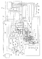
- FIG. 3 is a system configuration diagram of a fuel supply control device for an internal combustion engine.
- the internal combustion engine 1 includes a fuel supply control device 51.
- the fuel supply control device 51 can supply liquid fuel and gaseous fuel to the internal combustion engine 1 as two or more kinds of fuels having different properties, and switch and supply these liquid fuel and gaseous fuel during operation of the internal combustion engine 1.
- the control means 52 which performs the various fuel switching control to provide is provided.
- the control means 52 is, for example, an ECU (Electronic Control Unit).
- the control means 52 of this embodiment comprises a liquid fuel control unit 53 that controls the liquid fuel system and a gaseous fuel control unit 54 that controls the gaseous fuel system.
- the liquid fuel control unit 53 is connected to the liquid fuel pump 26, the liquid fuel injection valve 32, the purge control valve 37, the ignition coil 45, and the idle air amount control valve 50.
- the main stop valve 40 and the gaseous fuel injection valve 44 are connected to the gaseous fuel control unit 54.
- the gaseous fuel control unit 54 includes a gaseous fuel temperature sensor 68 that detects the temperature of the gaseous fuel decompressed by the decompression valve 41, and a gaseous fuel pressure sensor 69 that detects the pressure of the gaseous fuel decompressed by the decompression valve 41. And connected.
- the control means 52 connects the liquid fuel control unit 53 and the gaseous fuel control unit 54 to communicate control data with each other, and controls the liquid fuel supply amount, the gaseous fuel supply amount, and the intake air amount in a coordinated manner.
- the control means 52 ends (S16).
- this determination (S02) is YES
- the control means 52 determines the elapsed time T1, the increase value A of the intake air amount when switching from liquid fuel to gaseous fuel, and the intake air amount when switching from liquid fuel to gaseous fuel.
- the attenuation amount B, the increase value C of the intake air amount when switching from gas fuel to liquid fuel, and the attenuation amount D of the intake air amount when switching from gas fuel to liquid fuel are initialized to “0” (S03).
- the control means 52 determines whether or not the currently used fuel is liquid fuel (S04). If this determination (S04) is YES, the control means 52 proceeds to the processing of (S05) to (S15). If this determination (S04) is NO, the control means 52 proceeds to the processing of (S17) to (S27).
- the control means 52 determines whether or not the elapsed time T1 exceeds the first predetermined time t1 (T1> t1) (S10). If this determination (S10) is NO, the control means 52 returns to the measurement of the elapsed time T1 (S09). When this determination (S10) is YES, the control means 52 performs the fuel switching from the liquid fuel to the gaseous fuel (t1 in FIG. 2) (S11), and supplies the gaseous fuel according to the increased intake air amount. The amount is increased, and the elapsed time T1 from the start of increasing the intake air amount (S08) is counted (T1 + 1 ⁇ T1) (S12).
- the elapsed time T1 is counted (T1 + 1 ⁇ T1) (S21).
- the control means 52 determines whether the elapsed time T1 has exceeded the third predetermined time t3 (T1> t3) (S22). If this determination (S22) is NO, the control means 52 returns to the measurement of the elapsed time T1 (S21). If this determination (S22) is YES, the control means 52 performs fuel switching from gaseous fuel to liquid fuel (S23), increases the supply amount of liquid fuel according to the increased intake air amount, and The elapsed time T1 from the start of increasing the air amount (S20) is measured (T1 + 1 ⁇ T1) (S24).
- the engine speed can be improved and the controllability of the engine speed can be improved by eliminating a sudden change in the engine speed at the timing of returning to the normal intake air amount after fuel switching.
- the fuel supply control device 51 uses the control means 52 to increase the intake air amount (A, C) at the time of fuel switching and the attenuation amount of the intake air amount after the switching based on the coolant temperature at the time of fuel switching. (B, D) is set. For this reason, the fuel supply control device 51 sets the increase value and the attenuation amount of the intake air amount according to the temperature of the internal combustion engine 1 that has a large influence on the stability of the engine speed.
- predetermined times t1 to t4 set in advance for the liquid fuel and the gaseous fuel are set to values (t1 and t4) for the first predetermined time (t1, t3) and the second predetermined time (t3, t4), respectively.
- t2, t3, and t4) may be set corresponding to the fuel switching pattern.
- two sets of predetermined times are provided at a minimum.
- the increase value and the attenuation amount of the intake air amount are set based on the cooling water temperature of the internal combustion engine 1, but can also be set using the fuel temperature.
Landscapes
- Engineering & Computer Science (AREA)
- Chemical & Material Sciences (AREA)
- Oil, Petroleum & Natural Gas (AREA)
- Combustion & Propulsion (AREA)
- Mechanical Engineering (AREA)
- General Engineering & Computer Science (AREA)
- Electrical Control Of Air Or Fuel Supplied To Internal-Combustion Engine (AREA)
- Output Control And Ontrol Of Special Type Engine (AREA)
- Combined Controls Of Internal Combustion Engines (AREA)
Abstract
Description
そして、それらの燃料を切り替える際には、基本的な制御量の違いに加え、エンジン出力を維持基準として切り替えるか、排気ガスの清浄化を維持基準として切り替えるか、などによっても燃料制御の制御量が異なるため、様々なバランスをとった最適値等に合せるように制御を行うことが望まれる。
このため、この発明の内燃機関の燃料供給制御装置は、燃料切替後に次の燃料と吸入空気量の増量でエンジン回転数の安定化を図る従来の制御よりも、安定化が容易であり、収束を早めることができる。
内燃機関1は、吸気系として、エアクリーナ13と吸気管14とスロットルボディ15とサージタンク16と吸気マニホルド17とを順次に接続し、吸気ポート7に連通する吸気通路18を設けている。スロットルボディ15の吸気通路18には、スロットルバルブ19を設けている。また、内燃機関1は、排気系として、排気マニホルド20と触媒コンバータ21と排気管22とを順次に接続し、排気ポート8に連通する排気通路23を設けている。触媒コンバータ21は、触媒24を内蔵している。
前記液体燃料タンク25には、2ウェイチェックバルブ33を介してエバポ管34の一端側を接続している。エバポ管34は、他端側をキャニスタ35に接続している。キャニスタ35には、パージ管36の一端側を接続している。パージ管36は、他端側をスロットルボディ15に設けたスロットルバルブ19下流側の吸気通路18に連通している。パージ管36の途中には、パージ制御バルブ37を設けている。
前記内燃機関1は、気体燃料系として、気体燃料タンク38を設け、気体燃料タンク38に一端側が接続される気体燃料供給管39を設けている。気体燃料供給管39の途中には、主止弁40と減圧弁41とを設けている。減圧弁41は、圧力導入管42によりスロットルバルブ19下流側の吸気通路18に連通している。減圧弁41は、吸気通路18の吸気圧力を導入して気体燃料を減圧する。気体燃料供給管39の他端側は、気体燃料分配管43に接続している。気体燃料分配管43には、吸気マニホルド17に取り付けられた各気筒毎の気体燃料噴射弁44を接続している。気体燃料噴射弁44は、前記液体燃料噴射弁32に近接して吸気マニホルド17に取り付けられている。
この内燃機関1には、シリンダヘッドカバー4内をPCVバルブ46を介してサージタンク16の吸気通路18に連通するタンク側ブローバイガス通路47を設け、シリンダヘッドカバー4内をエアクリーナ13内に連通するクリーナ側ブローバイガス通路48を設けている。
また、内燃機関1は、スロットルバルブ19を迂回して吸気通路18を連通するバイパス空気通路49を設け、このバイパス空気通路49の途中にバイパス空気通路49の空気量を調整するアイドル空気量制御バルブ50を設けている。
前記液体燃料制御部53には、前記液体燃料ポンプ26と、液体燃料噴射弁32と、パージ制御バルブ37と、イグニションコイル45と、アイドル空気量制御バルブ50とを接続している。また、液体燃料制御部53には、吸気温度を検出する吸気温センサ55と、スロットルバルブ19のスロットル開度を検出するスロットル開度センサ56と、圧力導入管42に導入されたスロットルバルブ19下流側の吸気圧力を検出する吸気圧力センサ57と、排気ガスの空燃比を検出する空燃比センサ58と、排気ガスの酸素を検出する酸素センサ59と、冷却水温度を検出する水温センサ60と、ノッキングを検出するノッキングセンサ61と、エンジン回転数を検出するためクランク角を検出するクランク角センサ62と、吸気カム軸11(排気カム軸12)のカム角を検出するカム角センサ63と、人為操作によりON・OFFされる燃料切替スイッチ64とを接続し、メインスイッチ65及びフューズ66を介してバッテリ67を接続している。
前記気体燃料制御部54には、前記主止弁40と、気体燃料噴射弁44とを接続している。また、気体燃料制御部54には、減圧弁41で減圧された気体燃料の温度を検出する気体燃料温度センサ68と、減圧弁41で減圧された気体燃料の圧力を検出する気体燃料圧力センサ69とを接続している。
制御手段52は、液体燃料制御部53と気体燃料制御部54とを接続して相互に制御データを通信し、液体燃料供給量と気体燃料供給量と吸入空気量とを協調して制御する。
前記制御手段52は、燃料切替前後それぞれの所定時間にわたって保持する吸入空気量の増量値を設定するとともに、燃料切替後の吸入空気量の減衰量を設定し、増量した吸入空気量の減衰に応じた別の燃料の供給量とする。
また、前記制御手段52は、燃料切替時の冷却水温度に基づいて、燃料切替時の吸入空気量の増量値および切替後の吸入空気量の減衰量を設定する。
内燃機関1の燃料供給制御装置51は、人為操作による燃料切替スイッチ64の信号によって、液体燃料と気体燃料とのいずれか一の燃料から別の燃料に切り替える際に、燃料を切り替える前にあらかじめ吸入空気量を増量させてエンジン回転数を上げてから燃料の切替を行い、燃料の切替後に増量した吸入空気量の減衰を行うものである。吸入空気量の増量・減衰は、スロットルバルブ19を迂回するバイパス空気通路49に設けたアイドル空気量制御バルブ50によって行う。
燃料供給制御装置51の制御手段52は、図1に示すように、制御のプログラムがスタートすると(S01)、人為操作による燃料切替スイッチ64のONで燃料の切替信号が入力されたかを判断する(S02)。
この判断(S02)がNOの場合は、制御手段52は、エンドにする(S16)。この判断(S02)がYESの場合は、制御手段52は、経過時間T1、液体燃料から気体燃料に切り替える際の吸入空気量の増量値A、液体燃料から気体燃料に切り替える際の吸入空気量の減衰量B、気体燃料から液体燃料に切り替える際の吸入空気量の増量値C、気体燃料から液体燃料に切り替える際の吸入空気量の減衰量Dを「0」に初期化する(S03)。次に、制御手段52は、現在の使用燃料が液体燃料であるかを判断する(S04)。
この判断(S04)がYESの場合は、制御手段52は、(S05)~(S15)の処理に移行する。この判断(S04)がNOの場合は、制御手段52は、(S17)~(S27)の処理に移行する。
この判断(S10)がNOの場合は、制御手段52は、経過時間T1の計測(S09)に戻る。この判断(S10)がYESの場合は、制御手段52は、液体燃料から気体燃料への燃料切替を実施(図2のt1)し(S11)、増量した吸入空気量に応じて気体燃料の供給量を増量し、吸入空気量の増量開始(S08)からの経過時間T1を計時(T1+1→T1)する(S12)。次に、制御手段52は、経過時間T1が第2の所定時間t2を超えたか(T1>t2)を判断する(S13)。
この判断(S13)がNOの場合は、制御手段52は、経過時間T1の計時(S12)に戻る。この判断(S13)がYESの場合は、制御手段52は、吸入空気量の増量値Aから減衰量Bを引いて新たな吸入空気量の増量値Aとする減衰(A-B→A)を開始(図2のt2)し(S14)、吸入空気量の増量値Aが0になったか(A=0)を判断する(S15)。
この判断(S15)がNOの場合は、制御手段52は、吸入空気量の増量値Aの減衰(S14)に戻る。この判断(S15)がYESの場合は、制御手段52は、制御のプログラムをエンドにする(S16)。
この判断(S22)がNOの場合は、制御手段52は、経過時間T1の計測(S21)に戻る。この判断(S22)がYESの場合は、制御手段52は、気体燃料から液体燃料への燃料切替を実施し(S23)、増量した吸入空気量に応じて液体燃料の供給量を増量し、吸入空気量の増量開始(S20)からの経過時間T1を計時(T1+1→T1)する(S24)。次に、制御手段52は、経過時間T1が第4の所定時間t4を超えたか(T1>t4)を判断する(S25)。
この判断(S25)がNOの場合は、制御手段52は、経過時間T1の計時(S24)に戻る。この判断(S25)がYESの場合は、制御手段52は、吸入空気量の増量値Cから減衰量Dを引いて新たな吸入空気量の増量値Cとする減衰(C-D→C)を開始し(S26)、吸入空気量の増量値Cが0になったか(C=0)を判断する(S27)。
この判断(S27)がNOの場合は、制御手段52は、吸入空気量の増量値Cの減衰(S26)に戻る。この判断(S27)がYESの場合は、制御手段52は、制御のプログラムをエンドにする(S16)。
燃料供給制御装置51は、吸入空気量の増量分を、内燃機関1の冷却水温度に基づいて決める。その増量補正は、冷却水温度が低くなるほど増加傾向、水温上昇に対して増量補正は減少傾向となる。
燃料供給制御装置51は、液体燃料と気体燃料の2種の燃料に対してそれぞれに、また、切替前と切替後のそれぞれに、所定時間を設定している。すなわち、4つの所定時間t1~t4を設定している。また、経過時間T1を計るカウンタのカウントアップ(計時)は、1回目(切替前)と2回目(切替後)について継続して行っている。
燃料供給制御装置51は、図1における(S05)~(S15)の処理、あるいは(S17)~(S27)の処理に対して、1回目の所定時間t1、t3は燃料毎に別設定ができるようにし、冷却水温度に応じた燃料性状に最適な時間を設定できるようにしている。一方で、燃料供給制御装置51は、吸入空気量の増量を冷却水温度に応じて設定して、安定性を確保しているので、制御のスリム化のために、1回目の所定時間t1、t3の設定判断値は同一の時間長として設定することができる。同様に、2回目の所定時間t2、t4は、燃料に関わらず、同一の設定判断値に設定できる。
また、燃料供給制御装置51は、図1のフローチャートにおける(S05)~(S15)の処理、あるいは(S17)~(S27)の処理でみると、所定時間の判断が2回(t1とt2、あるいは、t3とt4)出てくるが、1回目の所定時間(t1とt3)の判断と2回目の所定時間(t3とt4)の判断では、増量する燃料種類が異なり、目的とする作用が異なる。増量分がエンジン回転数アップによる安定化に寄与し、この時間長については、一回目の所定時間(t1とt3)は、空気量増量によるエンジン回転数の安定化が得られればよく、2回目の所定時間(t2とt4)は、燃料切替時のエンジン回転数の安定化に必要な時間である。
このとき、燃料供給制御装置51は、吸入空気量を、基となる吸入空気量に冷却水温度に応じた増量分を加えて増量した吸入空気量状態とするとともに、この増量した吸入空気量に応じた供給量の液体燃料を供給している。従って、エンジン回転数が高まり、出力も若干高まるとしても、燃焼状態は吸入空気量の増量前と同等の状態として、排気ガスの成分比は増量前後でほぼ等しい状態(λ=1)である。
この状態で所定時間t1が経過し安定した後、燃料供給制御装置51は、一の燃料である液体燃料から別の燃料である気体燃料への燃料切替を行う。この瞬時的な切替は、既知の方法を利用すれば良い。そして、この切り替えの間も、経過時間T1の計時は継続している。燃料の切替を行う前後で吸入空気量の変更はなく、増量した吸入空気量状態のままとしているのに対し、この増量した吸入空気量に最適な別の燃料である気体燃料の供給量は、一の燃料である液体燃料の供給量とは異なる供給量となる。
この状態で所定時間t2が経過し安定した後、燃料供給制御装置51は、増量した吸入空気量を制御サイクルに従って当初に設定した減衰量ずつ変化させ、基本の吸入空気量に収束させる。この間も燃焼状態は吸入空気量の増量前と同等の状態として、排気ガスの成分比は増量前後でほぼ等しい状態(λ=1)である。
このため、燃料供給制御装置51は、燃料切替後の次の燃料と吸入空気量の増量でエンジン回転数の安定化を図る従来の制御よりも、安定化が容易であり、収束を早めることができる。また、燃料供給制御装置51は、液体燃料から気体燃料への切り替えの際だけでなく、気体燃料から液体燃料への切り替えの際にも吸入空気量を増量することで、燃料切替時の燃焼不安定によるエンジンストールを回避できる。
また、燃料供給制御装置51は、制御手段52によって、燃料切替前後それぞれの所定時間(t1・t2、t3・t4)にわたって保持する吸入空気量の増量値(A、C)を設定するとともに、燃料切替後の吸入空気量の減衰量(B、D)を設定し、増量した吸入空気量の減衰に応じた別の燃料の供給量としている。
このため、燃料供給制御装置51は、液体燃料から気体燃料への切り替え時と気体燃料から液体燃料への切り替え時の吸入空気量を個別に設定することで、燃料切替時のエンジン回転数の制御性を最適化でき、燃料切替後の通常の吸入空気量に復帰するタイミングでのエンジン回転数急変をなくして、エンジン回転数の制御性を向上できる。
さらに、燃料供給制御装置51は、制御手段52によって、燃料切替時の冷却水温度に基づいて、燃料切替時の吸入空気量の増量値(A、C)および切替後の吸入空気量の減衰量(B、D)を設定している。
このため、燃料供給制御装置51は、吸入空気量の増量値および減衰量をエンジン回転数の安定性に影響の大きい内燃機関1の温度に応じて設定するので、始動直後から完全暖機までいずれの場合でも燃料切替を安定的に行うことができ、燃料切替時のエンジン回転数の上昇量、収束時間を調整することが可能となり、一時的なエンジン回転数アップから復帰するタイミングでの急変をなくしてドライバビリティを向上できる。
また、燃料供給制御装置51は、吸入空気量の増量・減衰をバイパス空気通路49に設けたアイドル空気量制御バルブ50によって行ったが、スロットルバルブ19が電子制御式の場合は、スロットルバルブで行うこともできる。
さらに、液体燃料と気体燃料とに予め設定する所定時間t1~t4は、1回目の所定時間(t1、t3)と2回目の所定時間(t3、t4)とのそれぞれの値をセット(t1とt2、t3とt4)にしておき、燃料切替パターンに対応させて設定してもよい。2種の燃料では、燃料切替パターンが2つとなるので、所定時間のセットは最小限2セット設けることになる。
また、吸入空気量の増量値や減衰量は、内燃機関1の冷却水温度に基づいて設定したが、燃料温度を用いて設定することもできる。燃料温度は、液体燃料タンク25内の液体燃料ポンプ26内部あるいは燃料供給経路の液体燃料供給管29上に設けた燃料温度センサ(不図示)によって検出することができる。
さらに、上述実施例においては、人為操作による燃料切替スイッチ64のONによって燃料切替を行ったが、燃料の切り替えは、予め設定した切替条件が成立した時に、燃料切替スイッチ64がONとなるように制御することで、切替条件の成立に基づいて自動的な燃料切替を行うこともできる。切替条件としては、内燃機関1の冷却水温度が、内燃機関1の完全暖機状態であると判断できる設定温度以上であること、加減速が少ない部分負荷の運転状態であること、エンジン回転数変動の少ない定常運転状態であること、等とすることができる。
Claims (4)
- 性状の異なる2種以上の燃料を内燃機関に供給可能とし、内燃機関の運転中にこれらの燃料を切り替えて供給する多種燃料切替制御を行う内燃機関の燃料供給制御装置であって、
吸入空気量に対して複数の燃料のそれぞれの燃料性状に応じた燃料供給量を設定し供給するとともに、
いずれか一の燃料から別の燃料に切り替える際には、一の燃料の供給中に吸入空気量を所定量だけ増量してそれに応じた一の燃料の供給量とし、その後吸入空気量を増量したまま別の燃料に燃料切替を行って増量した吸入空気量に応じた別の燃料の供給量とする制御手段を備えることを特徴とする内燃機関の燃料供給制御装置。 - 前記制御手段は、燃料切替前後それぞれの所定時間にわたって保持する吸入空気量の増量値を設定するとともに、燃料切替後の吸入空気量の減衰量を設定し、
増量した吸入空気量の減衰に応じた別の燃料の供給量とすることを特徴とする請求項1に記載の内燃機関の燃料供給制御装置。 - 前記制御手段は、燃料切替時の冷却水温度に基づいて、燃料切替時の吸入空気量の増量値および切替後の吸入空気量の減衰量を設定することを特徴とする請求項1に記載の内燃機関の燃料供給制御装置。
- 前記制御手段は、一の燃料から別の燃料への切り替え時と別の燃料から一の燃料への切り替え時との吸入空気量を個別に設定することを特徴とする請求項2に記載の内燃機関の燃料供給制御装置。
Priority Applications (3)
| Application Number | Priority Date | Filing Date | Title |
|---|---|---|---|
| CN201180021003.8A CN102859151B (zh) | 2010-04-28 | 2011-04-08 | 用于内燃机的燃料供给控制设备 |
| DE112011101476.7T DE112011101476B4 (de) | 2010-04-28 | 2011-04-08 | Brennstoffzufuhrsteuervorrichtung für Brennkraftmaschine |
| JP2012512753A JP5729381B2 (ja) | 2010-04-28 | 2011-04-08 | 内燃機関の燃料供給制御装置 |
Applications Claiming Priority (2)
| Application Number | Priority Date | Filing Date | Title |
|---|---|---|---|
| JP2010103337 | 2010-04-28 | ||
| JP2010-103337 | 2010-04-28 |
Publications (1)
| Publication Number | Publication Date |
|---|---|
| WO2011136005A1 true WO2011136005A1 (ja) | 2011-11-03 |
Family
ID=44861317
Family Applications (1)
| Application Number | Title | Priority Date | Filing Date |
|---|---|---|---|
| PCT/JP2011/058938 Ceased WO2011136005A1 (ja) | 2010-04-28 | 2011-04-08 | 内燃機関の燃料供給制御装置 |
Country Status (4)
| Country | Link |
|---|---|
| JP (1) | JP5729381B2 (ja) |
| CN (1) | CN102859151B (ja) |
| DE (1) | DE112011101476B4 (ja) |
| WO (1) | WO2011136005A1 (ja) |
Cited By (4)
| Publication number | Priority date | Publication date | Assignee | Title |
|---|---|---|---|---|
| WO2014087595A1 (ja) * | 2012-12-04 | 2014-06-12 | 株式会社デンソー | 燃料供給装置 |
| JP2017057775A (ja) * | 2015-09-16 | 2017-03-23 | ヤンマー株式会社 | エンジン装置 |
| WO2017047161A1 (ja) * | 2015-09-16 | 2017-03-23 | ヤンマー株式会社 | エンジン装置 |
| US12085216B2 (en) | 2022-02-17 | 2024-09-10 | Arctic Cat Inc. | Multi-use fuel filler tube |
Families Citing this family (1)
| Publication number | Priority date | Publication date | Assignee | Title |
|---|---|---|---|---|
| JP6118238B2 (ja) * | 2013-11-28 | 2017-04-19 | 愛三工業株式会社 | マルチフューエルエンジンの燃料供給装置 |
Citations (3)
| Publication number | Priority date | Publication date | Assignee | Title |
|---|---|---|---|---|
| JP2004211610A (ja) * | 2003-01-06 | 2004-07-29 | Hitachi Ltd | バイフューエル型内燃機関の燃料噴射制御方法及び装置 |
| JP2006161804A (ja) * | 2004-11-12 | 2006-06-22 | Mazda Motor Corp | パワートレインの制御装置 |
| JP2008240578A (ja) * | 2007-03-26 | 2008-10-09 | Toyota Motor Corp | 多種燃料内燃機関 |
Family Cites Families (4)
| Publication number | Priority date | Publication date | Assignee | Title |
|---|---|---|---|---|
| JPS6296742A (ja) * | 1985-10-22 | 1987-05-06 | Mazda Motor Corp | エンジンのアイドル回転数制御装置 |
| JP2841499B2 (ja) | 1989-07-07 | 1998-12-24 | ソニー株式会社 | カセツトオートチエンジヤー |
| US20090071453A1 (en) * | 2007-09-14 | 2009-03-19 | William Francis Stockhausen | Bi-fuel Engine Using Hydrogen |
| JP5510649B2 (ja) * | 2010-04-13 | 2014-06-04 | スズキ株式会社 | 内燃機関の空燃比制御装置 |
-
2011
- 2011-04-08 CN CN201180021003.8A patent/CN102859151B/zh not_active Expired - Fee Related
- 2011-04-08 DE DE112011101476.7T patent/DE112011101476B4/de active Active
- 2011-04-08 WO PCT/JP2011/058938 patent/WO2011136005A1/ja not_active Ceased
- 2011-04-08 JP JP2012512753A patent/JP5729381B2/ja active Active
Patent Citations (3)
| Publication number | Priority date | Publication date | Assignee | Title |
|---|---|---|---|---|
| JP2004211610A (ja) * | 2003-01-06 | 2004-07-29 | Hitachi Ltd | バイフューエル型内燃機関の燃料噴射制御方法及び装置 |
| JP2006161804A (ja) * | 2004-11-12 | 2006-06-22 | Mazda Motor Corp | パワートレインの制御装置 |
| JP2008240578A (ja) * | 2007-03-26 | 2008-10-09 | Toyota Motor Corp | 多種燃料内燃機関 |
Cited By (14)
| Publication number | Priority date | Publication date | Assignee | Title |
|---|---|---|---|---|
| WO2014087595A1 (ja) * | 2012-12-04 | 2014-06-12 | 株式会社デンソー | 燃料供給装置 |
| JP2017057775A (ja) * | 2015-09-16 | 2017-03-23 | ヤンマー株式会社 | エンジン装置 |
| WO2017047161A1 (ja) * | 2015-09-16 | 2017-03-23 | ヤンマー株式会社 | エンジン装置 |
| WO2017047162A1 (ja) * | 2015-09-16 | 2017-03-23 | ヤンマー株式会社 | エンジン装置 |
| JP2017057774A (ja) * | 2015-09-16 | 2017-03-23 | ヤンマー株式会社 | エンジン装置 |
| KR20180030215A (ko) * | 2015-09-16 | 2018-03-21 | 얀마 가부시키가이샤 | 엔진 장치 |
| KR20180034657A (ko) * | 2015-09-16 | 2018-04-04 | 얀마 가부시키가이샤 | 엔진 장치 |
| CN108026844A (zh) * | 2015-09-16 | 2018-05-11 | 洋马株式会社 | 发动机装置 |
| KR101967591B1 (ko) | 2015-09-16 | 2019-04-09 | 얀마 가부시키가이샤 | 엔진 장치 |
| KR102010714B1 (ko) * | 2015-09-16 | 2019-08-13 | 얀마 가부시키가이샤 | 엔진 장치 |
| US10378461B2 (en) | 2015-09-16 | 2019-08-13 | Yanmar Co., Ltd. | Engine device |
| US10393035B2 (en) | 2015-09-16 | 2019-08-27 | Yanmar Co., Ltd. | Engine device |
| CN108026844B (zh) * | 2015-09-16 | 2021-02-12 | 洋马动力科技有限公司 | 发动机装置 |
| US12085216B2 (en) | 2022-02-17 | 2024-09-10 | Arctic Cat Inc. | Multi-use fuel filler tube |
Also Published As
| Publication number | Publication date |
|---|---|
| CN102859151A (zh) | 2013-01-02 |
| DE112011101476B4 (de) | 2015-02-05 |
| JP5729381B2 (ja) | 2015-06-03 |
| DE112011101476T5 (de) | 2013-02-28 |
| JPWO2011136005A1 (ja) | 2013-07-18 |
| CN102859151B (zh) | 2015-07-08 |
Similar Documents
| Publication | Publication Date | Title |
|---|---|---|
| CN101201020B (zh) | 灵活燃料的可变排量发动机的控制系统和方法 | |
| JP4719136B2 (ja) | エンジンの制御装置 | |
| JP4012893B2 (ja) | 内燃機関の制御装置 | |
| JP5729381B2 (ja) | 内燃機関の燃料供給制御装置 | |
| JP5373687B2 (ja) | バイフューエルエンジンのアイドル回転速度制御装置 | |
| JP2010180774A (ja) | 内燃機関の制御装置 | |
| JP2009270523A (ja) | 内燃機関の制御装置 | |
| JP2004100559A (ja) | 内燃機関の燃料噴射制御装置 | |
| JP2006016973A (ja) | 筒内噴射式内燃機関の制御装置 | |
| WO2011129267A1 (ja) | バイフューエルエンジンの空燃比学習制御装置 | |
| JP4937287B2 (ja) | 内燃機関の制御装置 | |
| JP2012202209A (ja) | 内燃機関の空燃比制御装置 | |
| JP5110119B2 (ja) | 多気筒内燃機関の制御装置 | |
| JP4457803B2 (ja) | 内燃機関の制御装置 | |
| JP3899922B2 (ja) | 内燃機関 | |
| JP2012246781A (ja) | 内燃機関の点火時期制御装置 | |
| JP2006220010A (ja) | 内燃機関の燃料噴射制御装置 | |
| JP5151879B2 (ja) | エンジンのアルコール濃度推定装置およびエンジンの制御装置 | |
| JP2006052664A (ja) | 内燃機関およびその制御方法 | |
| JP2012197798A (ja) | 多気筒内燃機関の制御装置 | |
| JP2005337102A (ja) | 内燃機関の燃料噴射制御装置 | |
| JP5240384B2 (ja) | 多気筒内燃機関の制御装置 | |
| JP6167659B2 (ja) | 内燃機関の燃料噴射制御装置 | |
| JP2014062526A (ja) | 内燃機関の燃料噴射制御装置 | |
| JP2024048280A (ja) | エンジン制御装置 |
Legal Events
| Date | Code | Title | Description |
|---|---|---|---|
| WWE | Wipo information: entry into national phase |
Ref document number: 201180021003.8 Country of ref document: CN |
|
| 121 | Ep: the epo has been informed by wipo that ep was designated in this application |
Ref document number: 11774789 Country of ref document: EP Kind code of ref document: A1 |
|
| WWE | Wipo information: entry into national phase |
Ref document number: 2012512753 Country of ref document: JP |
|
| WWE | Wipo information: entry into national phase |
Ref document number: 9231/DELNP/2012 Country of ref document: IN |
|
| WWE | Wipo information: entry into national phase |
Ref document number: 112011101476 Country of ref document: DE Ref document number: 1120111014767 Country of ref document: DE |
|
| 122 | Ep: pct application non-entry in european phase |
Ref document number: 11774789 Country of ref document: EP Kind code of ref document: A1 |