WO2017047162A1 - エンジン装置 - Google Patents
エンジン装置 Download PDFInfo
- Publication number
- WO2017047162A1 WO2017047162A1 PCT/JP2016/065255 JP2016065255W WO2017047162A1 WO 2017047162 A1 WO2017047162 A1 WO 2017047162A1 JP 2016065255 W JP2016065255 W JP 2016065255W WO 2017047162 A1 WO2017047162 A1 WO 2017047162A1
- Authority
- WO
- WIPO (PCT)
- Prior art keywords
- engine
- fuel
- mode
- gas
- speed
- Prior art date
Links
Images


Classifications
-
- F—MECHANICAL ENGINEERING; LIGHTING; HEATING; WEAPONS; BLASTING
- F02—COMBUSTION ENGINES; HOT-GAS OR COMBUSTION-PRODUCT ENGINE PLANTS
- F02D—CONTROLLING COMBUSTION ENGINES
- F02D19/00—Controlling engines characterised by their use of non-liquid fuels, pluralities of fuels, or non-fuel substances added to the combustible mixtures
- F02D19/06—Controlling engines characterised by their use of non-liquid fuels, pluralities of fuels, or non-fuel substances added to the combustible mixtures peculiar to engines working with pluralities of fuels, e.g. alternatively with light and heavy fuel oil, other than engines indifferent to the fuel consumed
- F02D19/0602—Control of components of the fuel supply system
- F02D19/0613—Switch-over from one fuel to another
-
- B—PERFORMING OPERATIONS; TRANSPORTING
- B63—SHIPS OR OTHER WATERBORNE VESSELS; RELATED EQUIPMENT
- B63H—MARINE PROPULSION OR STEERING
- B63H21/00—Use of propulsion power plant or units on vessels
-
- B—PERFORMING OPERATIONS; TRANSPORTING
- B63—SHIPS OR OTHER WATERBORNE VESSELS; RELATED EQUIPMENT
- B63H—MARINE PROPULSION OR STEERING
- B63H21/00—Use of propulsion power plant or units on vessels
- B63H21/32—Arrangements of propulsion power-unit exhaust uptakes; Funnels peculiar to vessels
-
- F—MECHANICAL ENGINEERING; LIGHTING; HEATING; WEAPONS; BLASTING
- F02—COMBUSTION ENGINES; HOT-GAS OR COMBUSTION-PRODUCT ENGINE PLANTS
- F02D—CONTROLLING COMBUSTION ENGINES
- F02D19/00—Controlling engines characterised by their use of non-liquid fuels, pluralities of fuels, or non-fuel substances added to the combustible mixtures
- F02D19/06—Controlling engines characterised by their use of non-liquid fuels, pluralities of fuels, or non-fuel substances added to the combustible mixtures peculiar to engines working with pluralities of fuels, e.g. alternatively with light and heavy fuel oil, other than engines indifferent to the fuel consumed
- F02D19/0602—Control of components of the fuel supply system
- F02D19/0607—Control of components of the fuel supply system to adjust the fuel mass or volume flow
- F02D19/061—Control of components of the fuel supply system to adjust the fuel mass or volume flow by controlling fuel injectors
-
- F—MECHANICAL ENGINEERING; LIGHTING; HEATING; WEAPONS; BLASTING
- F02—COMBUSTION ENGINES; HOT-GAS OR COMBUSTION-PRODUCT ENGINE PLANTS
- F02D—CONTROLLING COMBUSTION ENGINES
- F02D19/00—Controlling engines characterised by their use of non-liquid fuels, pluralities of fuels, or non-fuel substances added to the combustible mixtures
- F02D19/06—Controlling engines characterised by their use of non-liquid fuels, pluralities of fuels, or non-fuel substances added to the combustible mixtures peculiar to engines working with pluralities of fuels, e.g. alternatively with light and heavy fuel oil, other than engines indifferent to the fuel consumed
- F02D19/0602—Control of components of the fuel supply system
- F02D19/0613—Switch-over from one fuel to another
- F02D19/0615—Switch-over from one fuel to another being initiated by automatic means, e.g. based on engine or vehicle operating conditions
-
- F—MECHANICAL ENGINEERING; LIGHTING; HEATING; WEAPONS; BLASTING
- F02—COMBUSTION ENGINES; HOT-GAS OR COMBUSTION-PRODUCT ENGINE PLANTS
- F02D—CONTROLLING COMBUSTION ENGINES
- F02D19/00—Controlling engines characterised by their use of non-liquid fuels, pluralities of fuels, or non-fuel substances added to the combustible mixtures
- F02D19/06—Controlling engines characterised by their use of non-liquid fuels, pluralities of fuels, or non-fuel substances added to the combustible mixtures peculiar to engines working with pluralities of fuels, e.g. alternatively with light and heavy fuel oil, other than engines indifferent to the fuel consumed
- F02D19/0602—Control of components of the fuel supply system
- F02D19/0613—Switch-over from one fuel to another
- F02D19/0618—Switch-over from one fuel to another depending on the engine's or vehicle's position, e.g. on/off road or proximity to a harbor
-
- F—MECHANICAL ENGINEERING; LIGHTING; HEATING; WEAPONS; BLASTING
- F02—COMBUSTION ENGINES; HOT-GAS OR COMBUSTION-PRODUCT ENGINE PLANTS
- F02D—CONTROLLING COMBUSTION ENGINES
- F02D19/00—Controlling engines characterised by their use of non-liquid fuels, pluralities of fuels, or non-fuel substances added to the combustible mixtures
- F02D19/06—Controlling engines characterised by their use of non-liquid fuels, pluralities of fuels, or non-fuel substances added to the combustible mixtures peculiar to engines working with pluralities of fuels, e.g. alternatively with light and heavy fuel oil, other than engines indifferent to the fuel consumed
- F02D19/0623—Failure diagnosis or prevention; Safety measures; Testing
-
- F—MECHANICAL ENGINEERING; LIGHTING; HEATING; WEAPONS; BLASTING
- F02—COMBUSTION ENGINES; HOT-GAS OR COMBUSTION-PRODUCT ENGINE PLANTS
- F02D—CONTROLLING COMBUSTION ENGINES
- F02D19/00—Controlling engines characterised by their use of non-liquid fuels, pluralities of fuels, or non-fuel substances added to the combustible mixtures
- F02D19/06—Controlling engines characterised by their use of non-liquid fuels, pluralities of fuels, or non-fuel substances added to the combustible mixtures peculiar to engines working with pluralities of fuels, e.g. alternatively with light and heavy fuel oil, other than engines indifferent to the fuel consumed
- F02D19/0639—Controlling engines characterised by their use of non-liquid fuels, pluralities of fuels, or non-fuel substances added to the combustible mixtures peculiar to engines working with pluralities of fuels, e.g. alternatively with light and heavy fuel oil, other than engines indifferent to the fuel consumed characterised by the type of fuels
- F02D19/0642—Controlling engines characterised by their use of non-liquid fuels, pluralities of fuels, or non-fuel substances added to the combustible mixtures peculiar to engines working with pluralities of fuels, e.g. alternatively with light and heavy fuel oil, other than engines indifferent to the fuel consumed characterised by the type of fuels at least one fuel being gaseous, the other fuels being gaseous or liquid at standard conditions
- F02D19/0647—Controlling engines characterised by their use of non-liquid fuels, pluralities of fuels, or non-fuel substances added to the combustible mixtures peculiar to engines working with pluralities of fuels, e.g. alternatively with light and heavy fuel oil, other than engines indifferent to the fuel consumed characterised by the type of fuels at least one fuel being gaseous, the other fuels being gaseous or liquid at standard conditions the gaseous fuel being liquefied petroleum gas [LPG], liquefied natural gas [LNG], compressed natural gas [CNG] or dimethyl ether [DME]
-
- F—MECHANICAL ENGINEERING; LIGHTING; HEATING; WEAPONS; BLASTING
- F02—COMBUSTION ENGINES; HOT-GAS OR COMBUSTION-PRODUCT ENGINE PLANTS
- F02D—CONTROLLING COMBUSTION ENGINES
- F02D19/00—Controlling engines characterised by their use of non-liquid fuels, pluralities of fuels, or non-fuel substances added to the combustible mixtures
- F02D19/06—Controlling engines characterised by their use of non-liquid fuels, pluralities of fuels, or non-fuel substances added to the combustible mixtures peculiar to engines working with pluralities of fuels, e.g. alternatively with light and heavy fuel oil, other than engines indifferent to the fuel consumed
- F02D19/0663—Details on the fuel supply system, e.g. tanks, valves, pipes, pumps, rails, injectors or mixers
- F02D19/0686—Injectors
- F02D19/0689—Injectors for in-cylinder direct injection
-
- F—MECHANICAL ENGINEERING; LIGHTING; HEATING; WEAPONS; BLASTING
- F02—COMBUSTION ENGINES; HOT-GAS OR COMBUSTION-PRODUCT ENGINE PLANTS
- F02D—CONTROLLING COMBUSTION ENGINES
- F02D19/00—Controlling engines characterised by their use of non-liquid fuels, pluralities of fuels, or non-fuel substances added to the combustible mixtures
- F02D19/06—Controlling engines characterised by their use of non-liquid fuels, pluralities of fuels, or non-fuel substances added to the combustible mixtures peculiar to engines working with pluralities of fuels, e.g. alternatively with light and heavy fuel oil, other than engines indifferent to the fuel consumed
- F02D19/0663—Details on the fuel supply system, e.g. tanks, valves, pipes, pumps, rails, injectors or mixers
- F02D19/0686—Injectors
- F02D19/0692—Arrangement of multiple injectors per combustion chamber
-
- F—MECHANICAL ENGINEERING; LIGHTING; HEATING; WEAPONS; BLASTING
- F02—COMBUSTION ENGINES; HOT-GAS OR COMBUSTION-PRODUCT ENGINE PLANTS
- F02D—CONTROLLING COMBUSTION ENGINES
- F02D19/00—Controlling engines characterised by their use of non-liquid fuels, pluralities of fuels, or non-fuel substances added to the combustible mixtures
- F02D19/06—Controlling engines characterised by their use of non-liquid fuels, pluralities of fuels, or non-fuel substances added to the combustible mixtures peculiar to engines working with pluralities of fuels, e.g. alternatively with light and heavy fuel oil, other than engines indifferent to the fuel consumed
- F02D19/0663—Details on the fuel supply system, e.g. tanks, valves, pipes, pumps, rails, injectors or mixers
- F02D19/0686—Injectors
- F02D19/0694—Injectors operating with a plurality of fuels
-
- F—MECHANICAL ENGINEERING; LIGHTING; HEATING; WEAPONS; BLASTING
- F02—COMBUSTION ENGINES; HOT-GAS OR COMBUSTION-PRODUCT ENGINE PLANTS
- F02D—CONTROLLING COMBUSTION ENGINES
- F02D19/00—Controlling engines characterised by their use of non-liquid fuels, pluralities of fuels, or non-fuel substances added to the combustible mixtures
- F02D19/06—Controlling engines characterised by their use of non-liquid fuels, pluralities of fuels, or non-fuel substances added to the combustible mixtures peculiar to engines working with pluralities of fuels, e.g. alternatively with light and heavy fuel oil, other than engines indifferent to the fuel consumed
- F02D19/08—Controlling engines characterised by their use of non-liquid fuels, pluralities of fuels, or non-fuel substances added to the combustible mixtures peculiar to engines working with pluralities of fuels, e.g. alternatively with light and heavy fuel oil, other than engines indifferent to the fuel consumed simultaneously using pluralities of fuels
- F02D19/10—Controlling engines characterised by their use of non-liquid fuels, pluralities of fuels, or non-fuel substances added to the combustible mixtures peculiar to engines working with pluralities of fuels, e.g. alternatively with light and heavy fuel oil, other than engines indifferent to the fuel consumed simultaneously using pluralities of fuels peculiar to compression-ignition engines in which the main fuel is gaseous
- F02D19/105—Controlling engines characterised by their use of non-liquid fuels, pluralities of fuels, or non-fuel substances added to the combustible mixtures peculiar to engines working with pluralities of fuels, e.g. alternatively with light and heavy fuel oil, other than engines indifferent to the fuel consumed simultaneously using pluralities of fuels peculiar to compression-ignition engines in which the main fuel is gaseous operating in a special mode, e.g. in a liquid fuel only mode for starting
-
- F—MECHANICAL ENGINEERING; LIGHTING; HEATING; WEAPONS; BLASTING
- F02—COMBUSTION ENGINES; HOT-GAS OR COMBUSTION-PRODUCT ENGINE PLANTS
- F02D—CONTROLLING COMBUSTION ENGINES
- F02D31/00—Use of speed-sensing governors to control combustion engines, not otherwise provided for
- F02D31/001—Electric control of rotation speed
- F02D31/007—Electric control of rotation speed controlling fuel supply
- F02D31/009—Electric control of rotation speed controlling fuel supply for maximum speed control
-
- F—MECHANICAL ENGINEERING; LIGHTING; HEATING; WEAPONS; BLASTING
- F02—COMBUSTION ENGINES; HOT-GAS OR COMBUSTION-PRODUCT ENGINE PLANTS
- F02D—CONTROLLING COMBUSTION ENGINES
- F02D41/00—Electrical control of supply of combustible mixture or its constituents
- F02D41/0025—Controlling engines characterised by use of non-liquid fuels, pluralities of fuels, or non-fuel substances added to the combustible mixtures
- F02D41/0027—Controlling engines characterised by use of non-liquid fuels, pluralities of fuels, or non-fuel substances added to the combustible mixtures the fuel being gaseous
-
- F—MECHANICAL ENGINEERING; LIGHTING; HEATING; WEAPONS; BLASTING
- F02—COMBUSTION ENGINES; HOT-GAS OR COMBUSTION-PRODUCT ENGINE PLANTS
- F02D—CONTROLLING COMBUSTION ENGINES
- F02D41/00—Electrical control of supply of combustible mixture or its constituents
- F02D41/02—Circuit arrangements for generating control signals
- F02D41/04—Introducing corrections for particular operating conditions
- F02D41/042—Introducing corrections for particular operating conditions for stopping the engine
-
- F—MECHANICAL ENGINEERING; LIGHTING; HEATING; WEAPONS; BLASTING
- F02—COMBUSTION ENGINES; HOT-GAS OR COMBUSTION-PRODUCT ENGINE PLANTS
- F02D—CONTROLLING COMBUSTION ENGINES
- F02D41/00—Electrical control of supply of combustible mixture or its constituents
- F02D41/30—Controlling fuel injection
- F02D41/3011—Controlling fuel injection according to or using specific or several modes of combustion
- F02D41/3064—Controlling fuel injection according to or using specific or several modes of combustion with special control during transition between modes
-
- F—MECHANICAL ENGINEERING; LIGHTING; HEATING; WEAPONS; BLASTING
- F02—COMBUSTION ENGINES; HOT-GAS OR COMBUSTION-PRODUCT ENGINE PLANTS
- F02D—CONTROLLING COMBUSTION ENGINES
- F02D41/00—Electrical control of supply of combustible mixture or its constituents
- F02D41/30—Controlling fuel injection
- F02D41/3094—Controlling fuel injection the fuel injection being effected by at least two different injectors, e.g. one in the intake manifold and one in the cylinder
-
- F—MECHANICAL ENGINEERING; LIGHTING; HEATING; WEAPONS; BLASTING
- F02—COMBUSTION ENGINES; HOT-GAS OR COMBUSTION-PRODUCT ENGINE PLANTS
- F02M—SUPPLYING COMBUSTION ENGINES IN GENERAL WITH COMBUSTIBLE MIXTURES OR CONSTITUENTS THEREOF
- F02M37/00—Apparatus or systems for feeding liquid fuel from storage containers to carburettors or fuel-injection apparatus; Arrangements for purifying liquid fuel specially adapted for, or arranged on, internal-combustion engines
- F02M37/0047—Layout or arrangement of systems for feeding fuel
- F02M37/0064—Layout or arrangement of systems for feeding fuel for engines being fed with multiple fuels or fuels having special properties, e.g. bio-fuels; varying the fuel composition
-
- B—PERFORMING OPERATIONS; TRANSPORTING
- B63—SHIPS OR OTHER WATERBORNE VESSELS; RELATED EQUIPMENT
- B63H—MARINE PROPULSION OR STEERING
- B63H21/00—Use of propulsion power plant or units on vessels
- B63H21/12—Use of propulsion power plant or units on vessels the vessels being motor-driven
- B63H21/14—Use of propulsion power plant or units on vessels the vessels being motor-driven relating to internal-combustion engines
-
- B—PERFORMING OPERATIONS; TRANSPORTING
- B63—SHIPS OR OTHER WATERBORNE VESSELS; RELATED EQUIPMENT
- B63H—MARINE PROPULSION OR STEERING
- B63H21/00—Use of propulsion power plant or units on vessels
- B63H21/21—Control means for engine or transmission, specially adapted for use on marine vessels
-
- F—MECHANICAL ENGINEERING; LIGHTING; HEATING; WEAPONS; BLASTING
- F02—COMBUSTION ENGINES; HOT-GAS OR COMBUSTION-PRODUCT ENGINE PLANTS
- F02D—CONTROLLING COMBUSTION ENGINES
- F02D2200/00—Input parameters for engine control
- F02D2200/02—Input parameters for engine control the parameters being related to the engine
- F02D2200/10—Parameters related to the engine output, e.g. engine torque or engine speed
- F02D2200/1002—Output torque
-
- F—MECHANICAL ENGINEERING; LIGHTING; HEATING; WEAPONS; BLASTING
- F02—COMBUSTION ENGINES; HOT-GAS OR COMBUSTION-PRODUCT ENGINE PLANTS
- F02D—CONTROLLING COMBUSTION ENGINES
- F02D2200/00—Input parameters for engine control
- F02D2200/02—Input parameters for engine control the parameters being related to the engine
- F02D2200/10—Parameters related to the engine output, e.g. engine torque or engine speed
- F02D2200/101—Engine speed
-
- Y—GENERAL TAGGING OF NEW TECHNOLOGICAL DEVELOPMENTS; GENERAL TAGGING OF CROSS-SECTIONAL TECHNOLOGIES SPANNING OVER SEVERAL SECTIONS OF THE IPC; TECHNICAL SUBJECTS COVERED BY FORMER USPC CROSS-REFERENCE ART COLLECTIONS [XRACs] AND DIGESTS
- Y02—TECHNOLOGIES OR APPLICATIONS FOR MITIGATION OR ADAPTATION AGAINST CLIMATE CHANGE
- Y02T—CLIMATE CHANGE MITIGATION TECHNOLOGIES RELATED TO TRANSPORTATION
- Y02T10/00—Road transport of goods or passengers
- Y02T10/10—Internal combustion engine [ICE] based vehicles
- Y02T10/30—Use of alternative fuels, e.g. biofuels
-
- Y—GENERAL TAGGING OF NEW TECHNOLOGICAL DEVELOPMENTS; GENERAL TAGGING OF CROSS-SECTIONAL TECHNOLOGIES SPANNING OVER SEVERAL SECTIONS OF THE IPC; TECHNICAL SUBJECTS COVERED BY FORMER USPC CROSS-REFERENCE ART COLLECTIONS [XRACs] AND DIGESTS
- Y02—TECHNOLOGIES OR APPLICATIONS FOR MITIGATION OR ADAPTATION AGAINST CLIMATE CHANGE
- Y02T—CLIMATE CHANGE MITIGATION TECHNOLOGIES RELATED TO TRANSPORTATION
- Y02T70/00—Maritime or waterways transport
- Y02T70/50—Measures to reduce greenhouse gas emissions related to the propulsion system
- Y02T70/5218—Less carbon-intensive fuels, e.g. natural gas, biofuels
Definitions
- the present invention relates to an engine device employing a multi-fuel that can handle both gaseous fuel such as natural gas and liquid fuel such as heavy oil.
- a diesel engine is used as a driving source.
- exhaust gas from a diesel engine is rich in nitrogen oxides, sulfur oxides, particulate matter, and the like that are harmful substances that hinder environmental conservation. Therefore, in recent years, gas engines that can reduce the amount of harmful substances generated are becoming popular as engines that can replace diesel engines.
- a so-called gas engine that generates power using fuel gas such as natural gas supplies a cylinder with a mixed gas in which fuel gas is mixed with air and burns it (see Patent Document 1). Furthermore, as an engine device that combines the characteristics of a diesel engine and the characteristics of a gas engine, a premixed combustion method in which a gaseous fuel (fuel gas) such as natural gas is mixed with air and supplied to a combustion chamber for combustion, There is provided a dual fuel engine that can be used in combination with a diffusion combustion method in which liquid fuel such as heavy oil is injected into a combustion chamber and burned (see Patent Document 2).
- Patent Document 3 a multi-fuel engine or a bi-fuel engine that adjusts and switches between gas fuel and liquid fuel when switching from a gas mode using gaseous fuel to a diesel mode using liquid fuel.
- the gaseous fuel and the liquid fuel are adjusted at the same time as in the case of the cited document 3, and the gaseous fuel and the liquid fuel are adjusted at the same time.
- the engine speed is set to the target speed. It is adjusted to match.
- the threshold value that is the switching timing between the speed control and the increase / decrease control is often set to a constant value based on the supply amount of one of the gaseous fuel and the liquid fuel. For this reason, when the engine device is driven at a high speed, if the fuel in the operation mode after switching is changed to adjustment control, the supply amount is small, so the fuel supply amount is affected by load fluctuations. Fluctuates greatly, the engine speed of the engine device fluctuates abruptly, and in some cases, it suddenly stops. In addition, when the engine device is driven at a low rotational speed, if the fuel in the operation mode after switching is changed to adjustment control, the amount of supply increases, so the engine rotational speed of the engine device is excessive. (Overspeed) may occur.
- the amount of fuel supplied to drive the engine becomes less than the amount of fuel that does not control the speed (ie, the fuel that changes in a ramp function). It becomes impossible to control the engine device and it becomes overspeed.
- the engine device is overspeeded, it determines that the driving operation is in a dangerous area and stops in an emergency evacuation.
- the present invention includes an intake manifold that supplies air into a cylinder, an exhaust manifold that exhausts exhaust gas from the cylinder, a gas injector that mixes gaseous fuel with the air supplied from the intake manifold, and liquid in the cylinder
- a main fuel injection valve that injects and burns fuel, the gas injector and the main fuel injection valve are provided for each of the plurality of cylinders, and the gas fuel is injected into the cylinder
- an engine device driven in one of the diesel modes in which the liquid fuel is introduced into the cylinder the engine speed makes the engine device urgent when the operation mode is switched from one of the gas mode and the diesel mode to the other. When it is determined that the upper limit is reached , Is that switches instantly to the diesel mode.
- the engine mode when the operation mode is switched, when the reduction amount with the engine load at the start of the switching is larger than a predetermined amount, the engine mode may be switched to the diesel mode instantaneously.
- the engine mode when the ratio of the liquid fuel supply amount to the gaseous fuel supply amount becomes smaller than a predetermined value at the time of switching the operation mode, the engine mode may be instantaneously switched to the diesel mode.
- the liquid fuel supply amount after switching to the diesel mode is set based on the engine speed or engine load, and the liquid After the supply of fuel is started and the supply of the gaseous fuel is stopped, the supply amount of the liquid fuel is controlled. At this time, if the engine speed or the engine load is low, the supply amount of the liquid fuel after the instantaneous switching may be set to a small amount.
- the supply threshold of the first fuel to be input in the operation mode after the switching is increased by a control that increases monotonously.
- the control is performed by speed control based on the engine speed, and the switching threshold may be set based on the engine speed or the engine load. At this time, if the engine speed or the engine load is low, the switching threshold value may be set to a small amount.
- the amount of the second fuel supplied in the operation mode before the switching is adjusted based on the engine speed. It is controlled by speed control, and after the supply amount of the first fuel reaches the switching threshold value by the increase control, the supply amount of the second fuel may be decreased by a decrease control that monotonously decreases. . At this time, when the supply amount of the second fuel reaches the lower limit value by the reduction control, the supply of the second fuel is stopped.
- the mode when it is determined that the engine speed has approached the upper limit value for emergency stop of the engine device when the operation mode is switched, the mode is instantaneously switched to the diesel mode.
- the operation mode of the engine device can be switched to the diesel mode for emergency evacuation. That is, even when the engine load changes greatly when the operation mode is switched, the engine speed of the engine device can be prevented from reaching the upper limit engine speed, and an emergency stop of the engine device can be avoided. Therefore, since the engine speed does not increase to an engine speed exceeding the upper limit (overspeed), when this engine device is mounted on a ship, stable navigation can be continued without emergency stop of the ship. Can do.
- the switching threshold is set based on the engine speed or the engine load. Therefore, when operating at a low load or low speed, the engine speed exceeds the upper limit value. No increase to the number (overspeed), and it is possible to maintain good response to load fluctuations during operation at high load or high speed.
- the switching threshold value when the engine device is operating at a low load or low rotation, by setting the switching threshold value to a small value, the fuel supply after mode switching is performed without increasing the engine rotational speed to the target rotational speed. At the same time as switching to the speed control, the fuel supply before the mode switching can be stopped.
- the supply amount of fuel having a large influence on the engine speed is controlled by controlling the switching threshold value to a large value. Therefore, for example, even when the load suddenly decreases, the engine speed can be maintained near the target speed, and it is possible to avoid an increase to the engine speed that may lead to an emergency stop.
- the engine rotational speed exceeds the upper limit value (overspeed) when operating at low load or low rotational speed. It does not rise and can maintain good response to load fluctuations during operation under high load or high rotation. That is, when the engine device is operating at a low load or a low rotation, the liquid fuel can be instantaneously supplied by increasing the liquid fuel to a small value without increasing the engine rotation speed to the target rotation speed. At the same time as controlling the speed, the supply of gaseous fuel can be stopped.
- the engine device when the engine device is operating at a high load or high speed, a decrease in the engine speed due to insufficient fuel can be avoided by setting the amount of liquid fuel supplied to a large value, and the engine speed can be maintained even after instantaneous switching. The number can be maintained at the target rotational speed.
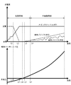
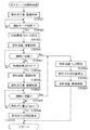
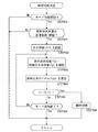
- FIG. 1 is an overall side view of a ship according to an embodiment of the present invention. It is side surface sectional drawing of an engine room. It is plane explanatory drawing of an engine room. It is the schematic which shows the structure of the fuel supply path of the engine apparatus in embodiment of this invention. It is the schematic which shows the structure of the intake / exhaust path in the engine apparatus. It is the schematic which represented typically the structure in the cylinder head in the engine apparatus. It is a control block diagram of the engine device. It is explanatory drawing which shows the operation
- 6 is a timing chart showing the relationship between the transition of the supply amount of fuel gas and fuel oil and the engine speed when the engine device at high load and high speed is switched from the gas mode to the diesel mode. It is a flowchart which shows the operation
- a ship 1 As shown in FIGS. 1 to 3, a ship 1 according to this embodiment includes a hull 2, a cabin 3 (bridge) provided on the stern side of the hull 2, and a funnel 4 (chimney) disposed behind the cabin 3. ) And a pair of propellers 5 and a rudder 6 provided at the lower rear part of the hull 2.
- a pair of skegs 8 are integrally formed on the stern side bottom 7.
- a propeller shaft 9 that rotates the propeller 5 is supported on each skeg 8.
- Each skeg 8 is formed symmetrically with respect to a hull center line CL (see FIG. 3) that divides the hull 2 in the left-right width direction. That is, in the first embodiment, twin skeg is adopted as the stern shape of the hull 2.
- a hull 10 is provided on the bow side and the center of the hull 2, and an engine room 11 is provided on the stern side of the hull 2.
- a pair of propulsion and power generation mechanisms 12, which serve both as a drive source for the propeller 5 and a power supply source for the ship 1, are distributed to the left and right across the hull center line CL.
- Each propeller 5 is rotationally driven by the rotational power transmitted from each propulsion and power generation mechanism 12 to the propulsion shaft 9.
- the interior of the engine room 11 is partitioned vertically by an upper deck 13, a second deck 14, a third deck 15 and an inner bottom plate 16.
- Each propulsion and power generation mechanism 12 of the first embodiment is installed on the inner bottom plate 16 at the lowest stage of the engine room 11.
- the hold 10 is divided into a plurality of sections.
- each propulsion and power generation mechanism 12 includes a medium speed engine device 21 (a dual fuel engine in the embodiment) that is a drive source of the propeller 5, and the power of the engine device 21 to the propulsion shaft 9.
- a medium speed engine means one that is driven at a rotational speed of about 500 to 1000 revolutions per minute.
- a “low speed” engine is driven at a rotational speed of 500 revolutions per minute
- a “high speed” engine is driven at a rotational speed of 1000 revolutions per minute.
- the engine device 21 of the embodiment is configured to be driven at a constant speed within a medium speed range (about 700 to 750 revolutions per minute).
- the engine device 21 includes a cylinder block 25 having an engine output shaft (crankshaft) 24 and a cylinder head 26 mounted on the cylinder block 25.
- a base stand 27 is installed directly or via a vibration isolator (not shown).
- the cylinder block 25 of the engine device 21 is mounted on the base table 27.
- the engine output shaft 24 extends in a direction along the longitudinal direction of the hull 2. That is, the engine device 21 is disposed in the engine room 11 in a state where the direction of the engine output shaft 24 is along the longitudinal direction of the hull 2.
- the speed reducer 22 and the shaft drive generator 23 are disposed on the stern side of the engine device 21.
- the rear end side of the engine output shaft 24 protrudes from the rear surface side of the engine device 21.
- a reduction gear 22 is connected to the rear end side of the engine output shaft so as to be able to transmit power.
- a shaft drive generator 23 is arranged on the side opposite to the engine device 21 with the speed reducer 22 interposed therebetween.
- the engine device 21, the speed reducer 22, and the shaft drive generator 23 are arranged in this order from the front in the engine room 11. In this case, the speed reducer 22 and the shaft drive generator 23 are disposed in or near the skeg 8 on the stern side. Therefore, it is possible to arrange the engine device 21 as close to the stern side as possible regardless of restrictions on the buttocks line of the ship 1, which contributes to making the engine room 11 compact.
- the propulsion shaft 9 is provided on the power transmission downstream side of the speed reducer 22.
- the outer shape of the speed reducer 22 protrudes below the engine device 21 and the shaft drive generator 23.
- the front end side of the propulsion shaft 9 is connected to the rear surface side of the overhanging portion so that power can be transmitted.
- the engine output shaft 24 (axial core line) and the propulsion shaft 9 are positioned coaxially in a plan view.
- the propulsion shaft 9 extends in the longitudinal direction of the hull 2 in a state of being eccentric in the vertical direction with respect to the engine output shaft 24 (axial core line). In this case, the propulsion shaft 9 is placed at a position lower than the shaft drive generator 23 and the engine output shaft 24 (shaft core line) and close to the inner bottom plate 16 in a side view. That is, the shaft drive generator 23 and the propulsion shaft 9 are distributed vertically and do not interfere with each other. Therefore, each propulsion and power generation mechanism 12 can be made compact.
- the constant speed power of the engine device 21 is branched and transmitted from the rear end side of the engine output shaft 24 to the shaft drive generator 23 and the propulsion shaft 9 via the speed reducer 22.
- a part of the constant speed power of the engine device 21 is reduced to a rotational speed of, for example, about 100 to 120 revolutions per minute by the speed reducer 22 and transmitted to the propulsion shaft 9.
- the propeller 5 is rotationally driven by the deceleration power from the speed reducer 22.
- the propeller 5 employs a variable pitch propeller capable of adjusting the ship speed by changing the blade angle of the propeller blades.
- a part of the constant speed power of the engine device 21 is increased to a rotational speed of, for example, about 1200 or 1800 revolutions per minute by the speed reducer 22 and transmitted to a PTO shaft that is rotatably supported by the speed reducer 22. Is done.
- the rear end side of the PTO shaft of the speed reducer 22 is connected to the shaft drive generator 23 so as to be able to transmit power, and the shaft drive generator 23 is driven to generate power based on the rotational power from the speed reducer 22.
- the generated power generated by driving the shaft drive generator 23 is supplied to the electrical system in the hull 2.
- the engine device 21 is connected to an intake path (not shown) for air intake and an exhaust path 28 for exhaust gas discharge.
- the air taken in through the intake path is sent into each cylinder 36 of the engine device 21 (inside the cylinder in the intake stroke). Since there are two engine devices 21, there are two exhaust paths 28.
- Each exhaust path 28 is connected to an extended path 29.
- the extension path 29 extends to the funnel 4 and is configured to communicate directly with the outside. Exhaust gas from each engine device 21 is discharged out of the ship 1 via each exhaust path 28 and extension path 29.
- a pair of propulsion and power generation mechanisms 12 combined with a shaft-driven generator 23 for generating power is provided, and the pair of propulsion and power generation mechanisms 12 are distributed to the engine room 11 in the hull 2 to the left and right with the hull center line CL interposed therebetween. Therefore, the engine installation space in the engine room 11 can be reduced as compared with the conventional structure in which a plurality of engines (main engine and auxiliary engine) are arranged in the engine room.
- the engine room 11 can be configured compactly by shortening the longitudinal length of the engine room 11, and as a result, it is easy to secure a hold space (a space other than the engine room 11) in the hull 2.
- the propulsion efficiency of the ship 1 can be improved by driving the two propellers 5.
- the two engine devices 21 serving as the main engine are provided, even if one engine device 21 fails and cannot be driven, the other engine device 21 can be navigated, and the marine prime mover device. As a result, the redundancy of the ship 1 can be secured.
- the propeller 5 can be rotationally driven and the shaft-driven generator 23 can be driven by the engine device 21, any one of the shaft-driven generators 23 can be reserved during normal navigation. Therefore, for example, when the power supply is stopped due to a failure of one engine device 21 or the shaft drive generator 23, the other shaft drive generator 23 is started, the frequency and voltage are established, and the power supply can be restored. That's fine. Further, when the engine device 21 is stopped at the time of navigation with only one engine device 21, the other stopped engine device 21, and thus the shaft drive generator 23 corresponding thereto, is started, and the frequency and What is necessary is just to establish voltage and to reset electric power feeding.
- the dual fuel engine 21 (hereinafter simply referred to as the “engine device 21”) has a premixed combustion method in which fuel gas such as natural gas is mixed with air and burns, and liquid fuel (fuel oil) such as heavy oil is diffused. Select and drive the diffusion combustion method to burn.
- FIG. 4 is a diagram showing a fuel system for the engine device 21
- FIG. 5 is a diagram showing an intake / exhaust system in the engine device 21
- FIG. 7 is a control block diagram in the engine device 21.
- the engine device 21 is supplied with fuel from two fuel supply paths 30, 31.
- a gas fuel tank 32 is connected to one fuel supply path 30, and the other A liquid fuel tank 33 is connected to the fuel supply path 31. That is, in the engine device 21, fuel gas is supplied from the fuel supply path 30 to the engine device 21, while fuel oil is supplied from the fuel supply path 31 to the engine device 21.
- the fuel supply path 30 includes a gas fuel tank 32 that stores gaseous fuel in a liquefied state, a vaporizer 34 that vaporizes liquefied fuel (fuel gas) in the gas fuel tank 32, and a fuel gas from the vaporizer 34 to the engine device 21. And a gas valve unit 35 for adjusting the supply amount. That is, the fuel supply path 30 is configured by sequentially arranging the vaporizer 34 and the gas valve unit 35 from the gas fuel tank 32 toward the engine device 21.
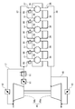
- the engine device 21 has a configuration in which a plurality of cylinders 36 (6 cylinders in the present embodiment) are arranged in series on a cylinder block 25.
- Each cylinder 36 communicates with an intake manifold (intake passage) 67 configured in the cylinder block 25 via an intake port 37.
- Each cylinder 36 communicates with an exhaust manifold (exhaust flow path) 44 disposed above the cylinder head 26 via an exhaust port 38.
- a gas injector 98 is disposed in the intake port 37 of each cylinder 36. Accordingly, air from the intake manifold 67 is supplied to each cylinder 36 via the intake port 37, while exhaust gas from each cylinder 36 is discharged to the exhaust manifold 44 via the exhaust port 38.
- the fuel gas is supplied from the gas injector 98 to the intake port 37, and the fuel gas is mixed with the air from the intake manifold 67 to preliminarily enter each cylinder 36. Supply mixed gas.
- the exhaust inlet of the turbine 49a of the supercharger 49 is connected to the exhaust outlet side of the exhaust manifold 44, and the air outlet (new air) of the intercooler 51 is connected to the air inlet side (new air inlet side) of the intake manifold 67. Outlet) is connected.
- the air discharge port (fresh air outlet) of the compressor 49 b of the supercharger 49 is connected to the air intake port (fresh air inlet) of the intercooler 51.
- a main throttle valve V1 is arranged between the compressor 49b and the intercooler 51, and the flow rate of air supplied to the intake manifold 67 is adjusted by adjusting the valve opening degree of the main throttle valve V1.
- An air supply bypass passage 17 for recirculating a part of the air discharged from the outlet of the compressor 49b to the inlet of the compressor 49b has an air inlet (new air inlet) side of the compressor 49b and an air outlet side of the intercooler 51. It is connected. That is, the air supply bypass passage 17 is connected to the connection portion between the intercooler 51 and the intake manifold 67 while being released to the outside air upstream of the air intake port of the compressor 49 b.
- An air supply bypass valve V2 is disposed on the air supply bypass passage 17, and the flow rate of air flowing from the downstream side of the intercooler 51 to the intake manifold 67 is adjusted by adjusting the valve opening degree of the air supply bypass valve V2. To do.
- An exhaust bypass passage 18 for bypassing the turbine 49 a connects the exhaust outlet side of the turbine 49 a and the exhaust outlet side of the exhaust manifold 44. That is, the exhaust bypass passage 18 is connected to a connection portion between the exhaust outlet of the turbine 49a and the exhaust inlet of the turbine 49a while being released to the outside air on the downstream side of the exhaust outlet of the turbine 49a.
- An exhaust bypass valve V3 is disposed on the exhaust bypass passage 18, and the amount of compressed air in the compressor 49b is adjusted by adjusting the valve opening of the exhaust bypass valve V3 to adjust the flow rate of exhaust gas flowing through the turbine 49a. Adjust.
- the engine device 21 includes a supercharger 49 that compresses air using exhaust gas from the exhaust manifold 44, and an intercooler 51 that cools the compressed air compressed by the supercharger 49 and supplies the compressed air to the intake manifold 67. ing.
- the engine device 21 is provided with a main throttle valve V1 at a connection point between the supercharger 49 outlet and the intercooler 51 inlet.
- the engine device 21 includes an exhaust bypass passage 18 that connects an outlet of the exhaust manifold 44 and an exhaust outlet of the supercharger 49, and an exhaust bypass valve V ⁇ b> 3 is disposed in the exhaust bypass passage 18.
- the air-fuel ratio optimum for the engine load is realized by controlling the opening degree of the exhaust bypass valve V3 in accordance with the fluctuation of the engine load even in the gas mode. it can. Therefore, when the load fluctuates, it is possible to prevent an excess or deficiency in the amount of air necessary for combustion, and the engine device 21 operates optimally even in the gas mode while using a turbocharger optimized in the diesel mode.
- the engine device 21 includes an air supply bypass passage 17 that bypasses the supercharger 49, and an air supply bypass valve V ⁇ b> 2 is disposed in the air supply bypass passage 17.
- an air supply bypass valve V ⁇ b> 2 is disposed in the air supply bypass passage 17.
- the engine device 21 connects the air supply bypass passage 17 at a position between the inlet of the intercooler 51 and the main throttle valve V1, and returns the compressed air discharged from the compressor 49b to the inlet of the compressor 49b.
- the responsiveness of the flow control by the exhaust bypass valve V3 can be compensated by the supply air bypass valve V2, and at the same time, the control width of the supply air bypass valve V2 can be supplemented by the exhaust bypass valve V3. Therefore, the followability of the air-fuel ratio control in the gas mode can be improved at the time of load fluctuation or switching of the operation mode in marine applications.
- a cylindrical cylinder 77 (cylinder 36) is inserted in the cylinder block 25, and the piston 78 reciprocates in the vertical direction in the cylinder 77, so that the cylinder 77
- the lower engine output shaft 24 is rotated.
- a main fuel injection valve 79 to which fuel oil (liquid combustion) is supplied from the fuel oil pipe 42 is inserted into the cylinder head 26 on the cylinder block 25 with the tip directed toward the cylinder 77.
- the fuel injection valve 79 has a tip disposed at the center position of the upper end surface of the cylinder 77 and injects fuel oil into the main combustion chamber formed by the upper surface of the piston 78 and the inner wall surface of the cylinder 77. Therefore, when the engine device 21 is driven by the diffusion combustion method, fuel oil is injected from the fuel injection valve 79 into the main combustion chamber in the cylinder 77, and in the main combustion chamber, it reacts with the compressed air and performs diffusion combustion. generate.
- an intake valve 80 and an exhaust valve 81 are slidably installed on the outer peripheral side of the main fuel injection valve 79.
- the intake valve 80 When the intake valve 80 is opened, air from the intake manifold 67 is sucked into the main combustion chamber in the cylinder 77, while the exhaust valve 81 is opened so that the combustion gas (exhaust gas) in the main combustion chamber in the cylinder 77 is opened. ) Is exhausted to the exhaust manifold 44.
- Each push rod (not shown) moves up and down in response to rotation of the camshaft (not shown), so that the rocker arm (not shown) swings and moves the intake valve 80 and the exhaust valve 81 up and down.
- a pilot fuel injection valve 82 that generates an ignition flame in the main combustion chamber is inserted obliquely with respect to each cylinder head 26 so that the tip thereof is disposed in the vicinity of the tip of the main fuel injection valve 79.
- the pilot fuel injection valve 82 employs a micro pilot injection system, and has a sub chamber in which pilot fuel is injected at the tip. That is, the pilot fuel injection valve 82 injects pilot fuel supplied from the common rail 47 into the sub chamber and burns it, thereby generating an ignition flame at the center position of the main combustion chamber in the cylinder 77.
- an ignition flame is generated in the pilot fuel injection valve 82, so that the premixed gas supplied to the main combustion chamber in the cylinder 77 via the intake valve 80 is generated. Reacts and generates premixed combustion.
- the engine device 21 has an engine control device 73 that controls each part of the engine device 21 as shown in FIG.
- the engine device 21 is provided with a pilot fuel injection valve 82, a fuel injection pump 89, and a gas injector 98 for each cylinder 36.
- the engine control device 73 gives control signals to the pilot fuel injection valve 82, the fuel injection pump 89, and the gas injector 98, so that the pilot fuel injection by the pilot fuel injection valve 82, the fuel oil supply by the fuel injection pump 89, and the gas Each of the gas fuel supply by the injector 98 is controlled.
- the engine device 21 includes a camshaft 200 including an exhaust cam, an intake cam, and a fuel cam (not shown) for each cylinder 36.
- the camshaft 200 transmits the rotational power from the crankshaft 24 via a gear mechanism (not shown), and rotates the exhaust cam, the intake cam, and the fuel cam, and the intake valve for each cylinder 36. 80 and the exhaust valve 81 are opened and closed, and the fuel injection pump 89 is driven.
- the engine device 21 also includes a speed governor 201 that adjusts the rack position of the control rack 202 in the fuel injection pump 89.
- the governor 201 measures the engine rotational speed of the engine device 21 from the rotational speed at the tip of the camshaft 200, sets the rack position of the control rack 202 in the fuel injection pump 89, and adjusts the fuel injection amount.
- the engine control device 73 gives control signals to the main throttle valve V1, the supply air bypass valve V2, and the exhaust gas bypass valve V3, respectively, and adjusts the valve opening, respectively, so that the air pressure (intake manifold pressure) in the intake manifold 67 is adjusted. adjust.
- the engine control device 73 receives the measurement signal from the pressure sensor 39 that measures the air pressure in the intake manifold 67 and detects the intake manifold pressure.
- the engine control device 73 receives a measurement signal from the load measuring device 19 such as a watt transducer or a torque sensor, and calculates a load applied to the engine device 21.
- the engine control device 73 receives a measurement signal from the engine rotation sensor 20 such as a pulse sensor that measures the rotation speed of the crankshaft 24 and detects the engine rotation speed of the engine device 21.
- the engine control device 73 controls the opening and closing of the control valve in the fuel injection pump 89 to generate combustion in each cylinder 36 at a predetermined timing. That is, by opening the control valve of the fuel injection pump 89 in accordance with the injection timing of each cylinder 36, the fuel oil is injected into each cylinder 36 through the main fuel injection valve 79 and ignited in the cylinder 36. In the diesel mode, the engine control device 73 stops the supply of pilot fuel and fuel gas.
- the engine control device 73 determines the main fuel injection valve in each cylinder 36 based on the engine load (engine output) measured by the load measuring device 19 and the engine speed measured by the engine rotation sensor 20.
- the injection timing 79 is feedback controlled.
- the engine 21 outputs the engine load required by the propulsion and power generation mechanism 12 and at the same time rotates at the engine speed corresponding to the propulsion speed of the ship.
- the engine control device 73 controls the opening of the main throttle valve V1 based on the intake manifold pressure measured by the pressure sensor 39, so that the compressed air having an air flow rate corresponding to the required engine output is excessive.
- the air is supplied from the feeder 49 to the intake manifold 67.
- the engine control device 73 When operating the engine device 21 in the gas mode, the engine control device 73 adjusts the valve opening degree in the gas injector 98 to set the flow rate of fuel gas supplied into each cylinder 36. Then, the engine control device 73 controls the opening and closing of the pilot fuel injection valve 82 to generate combustion in each cylinder 36 at a predetermined timing. That is, the gas injector 98 supplies fuel gas having a flow rate corresponding to the valve opening degree to the intake port 37, mixes it with air from the intake manifold 67, and supplies premixed fuel to the cylinder 36.
- the engine control device 73 determines the fuel gas flow rate by the gas injector 98 and each cylinder 36 based on the engine load measured by the load measuring device 19 and the engine speed measured by the engine rotation sensor 20. Feedback control of the injection timing by the pilot fuel injection valve 82 is performed. Further, the engine control device 73 adjusts the opening degrees of the main throttle valve V1, the supply air bypass valve V2, and the exhaust gas bypass valve V3 based on the intake manifold pressure measured by the pressure sensor 39. Thus, the intake manifold pressure can be adjusted to a pressure corresponding to the required engine output, and the air-fuel ratio with the fuel gas supplied from the gas injector 98 can be adjusted to a value corresponding to the engine output.
- the piston 78 descends in the cylinder 77 and the intake valve 80 opens, and the air from the intake manifold 67 enters the cylinder 77 through the intake port 37. Inflow (intake stroke).
- the fuel gas is supplied from the gas injector 98 to the intake port 37, the fuel gas is mixed with the air from the intake manifold 67, and the premixed gas is supplied into the cylinder 77.
- the engine device 21 compresses the air in the cylinder 77 by closing the intake valve 80 as the piston 78 rises (compression stroke).
- the gas mode when the piston 78 rises to near the top dead center, an ignition flame is generated by the pilot fuel injection valve 82 and the premixed gas in the cylinder 77 is combusted.
- the diesel mode by opening the control valve of the fuel injection pump 89, fuel oil is injected into the cylinder 77 through the main fuel injection valve 79 and ignited in the cylinder 77.
- the engine device 21 expands the combustion gas in the cylinder 77 (exhaust gas resulting from the combustion reaction) by combustion and lowers the piston 78 (expansion stroke). Thereafter, the piston 78 rises and the exhaust valve 81 is opened at the same time, whereby the combustion gas (exhaust gas) in the cylinder 77 is exhausted to the exhaust manifold 44 via the exhaust port 38 (exhaust stroke).
- the engine device 21 of the present embodiment includes six cylinders 36 (cylinders 77).
- the intake air shown in FIG. 8 at a timing determined for each cylinder 36.
- the state transitions in the order of stroke, compression stroke, expansion stroke, and exhaust stroke. That is, as shown in FIG. 9, each of the six cylinders 36 (# 1 to # 6) has an intake stroke, compression stroke, and # 4 in the order of # 1 ⁇ # 5 ⁇ # 3 ⁇ # 6 ⁇ # 2 ⁇ # 4. Transition to each state of the expansion stroke and the exhaust stroke.
- the fuel gas injection from the gas injector 98 in the intake stroke and the ignition by the pilot fuel injection valve 82 in the compression stroke are respectively performed as # 1 ⁇ # 5 ⁇ #. Execute in order of 3 ⁇ # 6 ⁇ # 2 ⁇ # 4. Similarly, when the engine device 21 is operating in the diesel mode, the fuel oil injection from the main fuel injection valve 79 in the compression stroke is performed as # 1 ⁇ # 5 ⁇ # 3 ⁇ # 6 ⁇ # 2 ⁇ # 4. Execute in this order.
- the dual fuel engine 21 (engine device 21) having the above-described schematic configuration
- the front / rear / left / right positional relationship in the configuration of the engine device 21 is designated with the connection side with the speed reducer 22 as the rear side.
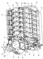
- the engine device 21 has a cylinder block 26 installed on a base table 27 (see FIG. 2) mounted with a cylinder head 26 in which a plurality of head covers 40 are arranged in a line in the front and rear direction. ing.
- the engine device 21 has a gas manifold (gaseous fuel pipe) 41 extending on the right side surface of the cylinder head 26 in parallel with the head cover 40 row, and a fuel oil pipe (parallel to the head cover 40 row on the left side surface of the cylinder block 25.
- a liquid fuel pipe) 42 is extended.
- an exhaust manifold (exhaust flow path) 44 which will be described later, extends in parallel to the head cover 40 row.
- a cylinder head upper cooling water pipe 46 connected to the cooling water passage in the cylinder head 26 is extended in parallel with the head cover 40 row.
- a common rail (pilot fuel pipe) 47 for supplying pilot fuel such as light oil extends in parallel with the head cover 40 row on the upper side of the cooling water pipe 46, similarly to the cooling water pipe 46.
- the cooling water pipe 46 is connected to and supported by the cylinder head 26, and the common rail 47 is connected to and supported by the cooling water pipe 46.
- the front end (exhaust outlet side) of the exhaust manifold 44 is connected to a supercharger 49 via an exhaust relay pipe 48. Therefore, the exhaust gas exhausted through the exhaust manifold 44 flows into the turbine 49a of the supercharger 49 through the exhaust relay pipe 48, whereby the turbine 49a rotates and the compressor 49b that is coaxial with the turbine 49a is rotated. Rotate.
- the supercharger 49 is disposed on the upper side of the front end of the engine device 21, and includes a turbine 49a on the right side and a compressor 49b on the left side.
- the exhaust outlet pipe 50 is disposed on the right side of the supercharger 49 and is connected to the exhaust outlet of the turbine 49a to exhaust the exhaust gas from the turbine 49a to the exhaust path 28 (see FIG. 2).
- An intercooler 51 for cooling the compressed air from the compressor 49b of the supercharger 49 is disposed below the supercharger 49. That is, the intercooler 51 is installed on the front end side of the cylinder block 25, and the supercharger 49 is placed on the intercooler 51.
- An air discharge port of the compressor 49b is provided in the left and right middle layer position of the supercharger 49 so as to open toward the rear (cylinder block 25 side).
- the upper surface of the intercooler 51 is provided with an air suction port that opens upward, and the compressed air discharged from the compressor 49b flows into the intercooler 51 through the air suction port.
- the air discharge port of the compressor 49b and the air intake port of the intercooler 51 are communicated with each other by an intake relay pipe 52 to which one end is connected.
- the intake relay pipe 52 has the above-described main throttle valve V1 (see FIG. 5).
- a cooling water pump 53, a pilot fuel pump 54, a lubricating oil pump (priming pump) 55, and a fuel oil pump 56 are installed on the outer peripheral side of the engine output shaft 24 on the front end surface (front surface) of the engine device 21. Yes. At this time, each of the cooling water pump 53 and the fuel oil pump 56 is disposed above and below the left side surface, and each of the pilot fuel pump 54 and the lubricating oil pump 55 is disposed above and below the right side surface. Further, a rotation transmission mechanism (not shown) that transmits the rotational power of the engine output shaft 24 is provided at the front end portion of the engine device 21.
- the rotational power from the engine output shaft 24 is transmitted through the rotation transmission mechanism, so that the coolant pump 53, the pilot fuel pump 54, the lubricating oil pump 55, and the like provided on the outer periphery of the engine output shaft 24, and Each of the fuel oil pumps 56 also rotates.
- a camshaft (not shown) having the front and rear axial directions is supported on the upper side of the cooling water pump 53, and the camshaft also rotates the engine output shaft 24 through the rotation transmission mechanism. Power is transmitted to rotate.
- An oil pan 57 is provided below the cylinder block 25, and lubricating oil flowing through the cylinder block 25 is accumulated in the oil pan 57.
- the lubricating oil pump 55 is connected to the oil pan 57 via a lower oil suction port via a lubricating oil pipe, and sucks lubricating oil accumulated in the oil pan 57.
- the lubricating oil pump 55 supplies the lubricating oil sucked from the oil pan 57 to the lubricating oil cooler 58 by connecting the upper discharge port to the lubricating oil inlet of the lubricating oil cooler 58 via the lubricating oil pipe.
- the lubricant cooler 58 has a lubricant oil inlet at the front and a lubricant oil outlet at the rear, and the lubricant oil outlet 59 is connected to the lubricant oil 59 via a lubricant pipe.
- the lubricant oil 59 has a lubricant oil inlet at the front and a lubricant oil outlet at the rear, and the lubricant oil outlet is connected to the cylinder block 25. Therefore, the lubricating oil sent from the lubricating oil pump 55 is cooled by the lubricating oil cooler 58 and then purified by the lubricating oil stiffness 59.
- the turbocharger 49 coaxially supports a compressor 49b and a turbine 49a that are arranged separately on the left and right, and the compressor 49b rotates based on the rotation of the turbine 49a introduced from the exhaust manifold 44 through the exhaust relay pipe 48.
- the supercharger 49 includes an intake filter 63 that removes outside air to be introduced, and a fresh air passage pipe 64 that connects the intake filter 63 and the compressor 49b on the left side of the compressor 49b on the fresh air intake side.
- the compressor 49 b rotates in synchronization with the turbine 49 a, so that outside air (air) sucked by the intake filter 63 is introduced into the compressor 49 b through the supercharger 49.
- the compressor 49b compresses the air sucked from the left side and discharges the compressed air to the intake relay pipe 52 installed on the rear side.
- the intake relay pipe 52 is opened at the upper front and connected to the discharge port behind the compressor 49b, while the lower side is opened and connected to the intake port on the upper surface of the intercooler 51.
- the intercooler 51 is connected to one end of the air supply bypass pipe 66 (the air supply bypass passage 17) at a branch port provided in the front air passage, and a part of the compressed air cooled by the intercooler 51. Is discharged to the air supply bypass pipe 66.
- the other end of the supply air bypass pipe 66 is connected to a branch port provided in front of the new air passage pipe 64, and a part of the compressed air cooled by the intercooler 51 passes through the supply air bypass pipe 66. It circulates in the pipe 64 and merges with the outside air from the intake filter 63. Further, the air supply bypass pipe 66 is provided with an air supply bypass valve V2 in the middle thereof.
- the intercooler 51 cools the compressed air based on the heat exchange action with the cooling water supplied from the water supply pipe when the compressed air from the compressor 49b flows from the left rear side through the intake relay pipe 52.
- the compressed air cooled in the left chamber flows through the front ventilation path and is introduced into the right chamber, and then is discharged to the intake manifold 67 through the discharge port provided at the rear of the right chamber.
- the intake manifold 67 is provided on the right side surface of the cylinder block 25, and extends below and in front of the gas manifold 41 in parallel with the head cover 40 row. Note that the flow rate of the compressed air to be supplied to the intake manifold 67 is set by determining the flow rate of the compressed air to be circulated from the intercooler 51 to the compressor 49b according to the opening degree of the air supply bypass valve V2.
- the turbine 49 a of the supercharger 49 has a rear suction port connected to the exhaust relay pipe 48 and a right discharge port connected to the exhaust outlet pipe 50.
- the supercharger 49 introduces exhaust gas from the exhaust manifold 44 into the turbine 49a via the exhaust relay pipe 48, rotates the turbine 49a and simultaneously rotates the compressor 49b, and sends the exhaust gas to the exhaust outlet pipe. 50 is exhausted to the exhaust path 28 (see FIG. 2).
- the exhaust relay pipe 48 is opened at the rear and connected to the discharge port of the exhaust manifold 44 via the bellows pipe 68, while the front is opened and connected to the suction port at the rear of the turbine 49a. Yes.
- a branch port is provided on the right side surface at a midway position of the exhaust relay pipe 48, and one end of an exhaust bypass pipe 69 (exhaust bypass flow path 18) is connected to the branch port of the exhaust relay pipe 48. .
- the other end of the exhaust bypass pipe 69 is connected to a merging port provided at the rear of the exhaust outlet pipe 50, and a part of the exhaust gas discharged from the exhaust manifold 44 is exhausted without passing through the supercharger 49. Bypass to 50.
- the exhaust bypass pipe 69 is provided with an exhaust bypass valve V3 in the middle thereof, and the flow rate of exhaust gas to be bypassed from the exhaust manifold 44 to the exhaust outlet pipe 50 according to the opening degree of the exhaust bypass valve V3. The exhaust gas flow rate to be set and supplied to the turbine 49a is adjusted.
- a machine-side operation control device 71 that controls starting and stopping of the engine device 21 is fixed to the left side surface of the intercooler 51 via a support stay (support member) 72.
- the machine-side operation control device 71 includes a switch for accepting start / stop of the engine device 21 by an operator, and a display for displaying the state of each part of the engine device 21.
- a governor 201 is fixed to the front end of the left side surface of the cylinder head 26.
- An engine starter 75 that starts the engine device 21 is fixed to the rear end side of the left side surface of the cylinder block 25.
- an engine control device 73 that controls the operation of each part of the engine device 21 is fixed to the rear end surface of the cylinder block 25 via a support stay (support member) 74.
- a flywheel 76 that is connected and rotated with the speed reducer 22 is installed, and an engine control device 73 is disposed on the flywheel 76.
- the engine control device 73 is electrically connected to sensors (pressure sensors and temperature sensors) in each part of the engine device 21 to collect temperature data, pressure data, and the like of each part of the engine device 21, and electromagnetics in each part of the engine device 21.
- a signal is given to a valve or the like to control various operations of the engine device 21 (fuel oil injection, pilot fuel injection, gas injection, cooling water temperature adjustment, etc.).
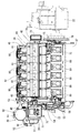
- the cylinder block 25 has a stepped portion on the upper left side surface, and the same number of fuel injection pumps 89 as the head cover 40 and the cylinder head 26 are installed on the upper surface of the stepped portion of the cylinder block 25.
- the fuel injection pumps 89 are arranged in a line along the left side surface of the cylinder block 25, the left side surface is connected to the fuel oil pipe (liquid fuel pipe) 42, and the upper end thereof is connected to the fuel discharge pipe 90. And connected to the left side surface of the right front cylinder head 26.
- One of the upper and lower fuel oil pipes 42 is an oil supply pipe that supplies fuel oil to the fuel injection pump 89, and the other is an oil return pipe that returns the fuel oil from the fuel injection pump 89.
- the fuel discharge pipe 90 is connected to the main fuel injection valve 79 (see FIG. 6) via a fuel flow path in the cylinder head 26, so that the fuel oil from the fuel injection pump 89 is supplied to the main fuel injection valve 79. Supply.
- the fuel injection pump 89 is arranged on the left side with respect to the head cover 40 row at a position on the left side of the cylinder head 26 connected by the fuel discharge pipe 90 on the step portion of the cylinder block 25.
- the fuel injection pumps 89 are arranged in a line at a position sandwiched between the cylinder head 26 and the fuel oil pipe 42.
- the fuel injection pump 89 pushes up the plunger by rotating a pump cam on a camshaft (not shown) in the cylinder block 25.
- the fuel injection pump 89 raises the fuel oil supplied from the fuel oil pipe 42 to a high pressure by pushing up the plunger, and supplies the high-pressure fuel oil to the fuel injection pump 89 in the cylinder head 26 via the fuel discharge pipe 90. Supply.
- the front end of the common rail 47 is connected to the discharge side of the pilot fuel pump 54, and the pilot fuel discharged from the pilot fuel pump 54 is supplied to the common rail 47.
- the gas manifold 41 extends along the head cover 40 row at a height position between the exhaust manifold 44 and the intake manifold 67.
- the gas manifold 41 includes a gas main pipe 41a having a front end connected to the gas inlet pipe 97 and extending in the front-rear direction, and a plurality of gas branch pipes 41b branched from the upper surface of the gas main pipe 41a toward the cylinder head 26.
- the gas main pipe 41a has connection flanges on the upper surface thereof at equal intervals, and is fastened to the inlet side flange of the gas branch pipe 41b.
- the gas branch pipe 41b connects the end portion on the opposite side to the connecting portion with the gas main pipe 41a to the right side surface of the sleeve into which the gas injector 98 is inserted from above.
- the engine control device 73 when the engine load is in a low load range (load range of load L4 or less) and lower than a predetermined load L1, the engine control device 73 performs the valve opening of the main throttle valve V1. Perform feedback control (PID control). At this time, the engine control device 73 sets a target value (target pressure) of the intake manifold pressure corresponding to the engine load. The engine control device 73 receives the measurement signal from the pressure sensor 39, confirms the measured value (measured pressure) of the intake manifold pressure, and obtains the difference from the target pressure. Thus, the engine control device 73 performs PID control of the valve opening degree of the main throttle valve V1 based on the difference value between the target pressure and the measured pressure, and brings the air pressure of the intake manifold 67 closer to the target pressure.
- PID control PID control
- the engine control device 73 performs map control on the valve opening of the main throttle valve V1 when the engine load is equal to or greater than the predetermined load L1. At this time, the engine control device 73 refers to the data table DT1 that stores the valve opening of the main throttle valve V1 with respect to the engine load, and sets the valve opening of the main throttle valve V1 corresponding to the engine load. The engine control device 73 controls the main throttle valve V1 to be fully opened when the engine load is equal to or greater than the load L2 (L1 ⁇ L2 ⁇ Lth ⁇ L4). Note that the load L2 is set in a low load region and lower than the load Lth at which the intake manifold pressure becomes atmospheric pressure.
- the engine control device 73 controls the supply air bypass valve V2 to be fully closed when the engine load is in a low load range and lower than a predetermined load L3 (Lth ⁇ L3 ⁇ L4).
- the engine control device 73 performs feedback control (PID control) on the valve opening degree of the air supply bypass valve V2 when the engine load is equal to or greater than the predetermined load L3.
- PID control feedback control
- the engine control device 73 executes PID control of the valve opening degree of the supply air bypass valve V2 based on the difference value between the target pressure corresponding to the engine load and the pressure measured by the pressure sensor 39, and Bring the air pressure closer to the target pressure.
- the engine control device 73 performs map control on the valve opening degree of the exhaust bypass valve V3 over the entire engine load.
- the engine control device 73 refers to the data table DT2 that stores the valve opening degree of the exhaust bypass valve V3 with respect to the engine load, and sets the valve opening degree of the exhaust bypass valve V3 corresponding to the engine load. That is, when the engine load is lower than the predetermined load L1, the exhaust bypass valve V3 is fully opened. When the engine load is higher than the predetermined load L1, the opening degree of the exhaust bypass valve V3 is monotonously decreased with respect to the engine load. At L2, the exhaust bypass valve V3 is fully opened.
- the exhaust bypass valve V3 When the engine load is higher than the predetermined load L2 and lower than or equal to the predetermined load L3, the exhaust bypass valve V3 is fully closed, and when the engine load becomes higher than the predetermined load L3 in the low load region, the exhaust bypass valve Monotonically increase the opening of V3. That is, the exhaust bypass valve V3 is gradually opened.
- the engine control device 73 fully opens the opening of the main throttle valve V1 when the load (engine load) applied to the engine is in a low load range and higher than the first predetermined load L3. Further, the engine control device 73 performs feedback control (PID control) on the air supply bypass valve V2 and simultaneously performs map control on the exhaust bypass valve V3, so that the pressure of the intake manifold 67 is determined according to the load. Adjust to the target value.
- PID control feedback control
- the pressure of the intake manifold 67 is controlled by controlling the opening of the supply air bypass valve V2 in accordance with the fluctuation of the engine load even in the gas mode operation. Good response can be obtained. Therefore, when the load fluctuates, excess and deficiency of the amount of air necessary for combustion can be prevented, and even the engine device 21 using the supercharger 49 optimized in the diesel mode can be optimally operated in the gas mode.
- the opening degree of the exhaust bypass valve V3 in accordance with the fluctuation of the engine load, it is possible to supply the engine device 21 with air that matches the air-fuel ratio necessary for the combustion of the gaseous fuel.
- the response speed to the load fluctuation in the gas mode can be increased by using the control operation by the responsive air supply bypass valve V2 together, the amount of air necessary for combustion is insufficient at the time of the load fluctuation. Based on knocking can be prevented.
- the engine control device 73 performs map control based on the data table DT1 for the main throttle valve V1.
- the supply air bypass valve V2 is fully closed and the exhaust gas bypass valve V3 is fully opened. That is, when the exhaust manifold 44 pressure is a negative pressure lower than the atmospheric pressure, surging in the supercharger 49 can be prevented by fully opening the exhaust bypass valve V3 and stopping the driving of the turbine 49a. Further, by fully closing the supply air bypass valve V2, the control of the intake manifold pressure by the main throttle valve V1 can be made highly responsive when the load is low.
- the engine load is equal to or higher than the second predetermined load L1 and lower than the third predetermined load L2, which is a value between the first and second predetermined loads L3 and L1
- data is sent to the main throttle valve V1.
- Map control based on the table DT1 is performed.
- the air supply bypass valve V2 is fully closed, and the exhaust bypass valve V3 is subjected to map control based on the data table DT2.
- the main throttle valve V1 is fully opened, while the supply air bypass valve V2 and the exhaust bypass valve V3 are fully closed, so that the gas mode can be switched from the diesel mode. .
- FIG. 14 is a flowchart showing the basic operation of fuel control in the engine device 21 operating in the gas mode
- FIG. 17 is a flowchart showing the basic operation of fuel control in the engine device 21 operating in the diesel mode.
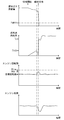
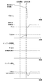
- 15 and 18 are timing charts at the time of switching when the engine device 21 is operated at a low rotational speed and a low load
- FIGS. 16 and 19 illustrate the engine device 21 at a high rotational speed and It is a timing chart at the time of the change at the time of making it drive
- the engine control device 73 uses a fuel gas supply amount (fuel gas injection amount) supplied into the cylinder 77 (cylinder 36) as shown in FIG.
- speed control based on a signal from the engine rotation sensor 20 is performed (STEP 501). That is, the engine control device 73 adjusts the fuel gas injection amount from the gas injector 98 by performing feedback control (PID control) with respect to the opening of the gas injector 98, and executes speed control of the fuel gas supply amount. .
- PID control feedback control
- the engine control device 73 determines whether or not the operation of the engine device 21 is switched to the diesel mode (STEP 502). In the engine control device 73, for example, an abnormality in the gas mode operation by the engine device 21 (eg, fuel gas pressure drop, intake manifold pressure drop, gas temperature rise, air temperature rise, or disconnection of each sensor, etc.) has occurred. In the case where the engine device 21 is operating in the diesel mode, the engine device 21 is determined to be switched to the diesel mode when the vehicle is navigating outside the restricted sea area that regulates NOx (nitrogen oxide) and SOx (sulfur oxide) emissions.
- NOx nitrogen oxide
- SOx sulfur oxide
- the engine control device 73 determines that the operation of the engine device 21 is switched to the diesel mode (Yes in STEP502), the control operation of the fuel oil supply amount is changed from the ramp function (proportional function) increase control to the speed control.
- a switching threshold value Foth serving as a reference for switching is set (STEP 503).
- the engine control device 73 refers to the threshold setting table for determining the switching threshold value Foth based on the engine speed and the engine load, and the measurement signals (engine load and engine speed) transmitted from the load measuring device 19 and the engine rotation sensor 20 respectively.
- the switching threshold value Foth is set according to the rotation speed).
- the switching threshold Foth is set to a small amount. If the engine load is low, the switching threshold Foth is set to a small amount. That is, if the engine speed is low and the engine load is low, the switching threshold value Foth is set to a small amount (for example, the threshold value Foth1 in FIG. 15), while the engine speed is high. If the engine load is high, the switching threshold Foth is set to a large amount (for example, the threshold Foth2 in FIG. 16).
- the engine control device 73 monotonously adjusts the fuel oil supply amount from the fuel injection pump 89 to the main fuel injection valve 79 in a ramp function with respect to time in order to control the fuel injection amount from the main fuel injection valve 79. Increase (STEP 504). That is, the engine control device 73 operates the speed governor 201 to change the rack position of the control rack 202 in the fuel injection pump 89 to increase the fuel oil supply amount.
- the engine control device 73 confirms the rack position of the control rack 202 through the governor 201 to confirm the fuel oil supply amount from the fuel oil supply amount, and the fuel oil supply amount becomes equal to or greater than the switching threshold value Foth.
- the control operation of the fuel oil supply amount is switched to the speed control based on the signal from the engine rotation sensor 20 (STEP 506). That is, the engine control device 73 adjusts the fuel oil injection amount from the main fuel injection valve 79 by performing feedback control (PID control) with respect to the rack position of the control rack 202 in the fuel injection pump 89, and the fuel oil supply amount.
- PID control feedback control
- the engine control device 73 switches the control operation of the fuel gas supply amount from the speed control to the ramp function (proportional function) reduction control (STEP 507). That is, the fuel gas injection amount from the gas injector 98 is monotonously decreased in a ramp function with respect to time. At this time, the engine control device 73 performs the reduction control of the fuel gas supply amount by shortening the valve opening period of the gas injector 98 stepwise. When the fuel gas supply amount falls below the minimum value (lower limit value) Fgmin by confirming the valve opening period of the gas injector 98 or the like (NO in STEP 508), the engine control device 73 supplies the gas from the gas valve unit 35. Stop (STEP509).
- the fuel oil supply amount is controlled to increase and the fuel gas supply amount is controlled.
- the speed of the engine By controlling the speed of the engine, the engine speed can be maintained at the target speed.
- the fuel oil supply amount reaches the switching threshold value Foth
- the fuel oil supply amount is subjected to speed control, and the fuel gas supply amount is controlled to decrease to maintain the engine speed at the target speed.
- the switching threshold value Foth is set according to the load and the rotational speed of the engine device 21, the engine rotational speed increases to the rotational speed (overspeed) exceeding the upper limit value when operating at low load and low speed. Therefore, it is possible to maintain good response to load fluctuations during operation under high load and high rotation.
- the switching threshold value Foth is set to a small value Foth1 without increasing the engine speed to the target speed.
- the fuel gas supply can be stopped at the same time as the fuel oil supply is switched to the speed control.
- the switching threshold value Foth is set to a large value Foth2
- the fuel having a great influence on the engine speed is reduced.
- the supply amount will be controlled. Therefore, for example, even when the load suddenly decreases, the engine speed can be maintained near the target speed, and it is possible to avoid an increase to the engine speed that may lead to an emergency stop.
- the engine control device 73 sets the fuel oil supply amount (fuel oil injection amount) supplied into the cylinder 77 (cylinder 36) as shown in FIG. In order to bring the engine speed close to the target value, speed control based on a signal from the engine speed sensor 20 is performed (STEP 601).
- the engine control device 73 determines to switch the operation of the engine device 21 to the gas mode (YES in STEP 602), the engine control device 73 has a reference for switching the control operation of the fuel gas supply amount from the speed control to the ramp function increase control.
- the switching threshold value Fgth is set (STEP 603).
- the engine control device 73 determines that the operation of the engine device 21 is switched to the gas mode, for example, when navigating from the vicinity of the restricted sea area that regulates the emission amount of NOx and SOx to the restricted sea area. To do. Further, the engine control device 73 sets the switching threshold Fgth with reference to a threshold setting table that determines the switching threshold Fgth based on the engine speed and the engine load. In the threshold setting table, the switching threshold Fgth is set to a small amount if the engine speed is low, and the switching threshold Fgth is set to a small amount if the engine load is low.
- the switching threshold Fgth is set to a small amount (for example, the threshold Fgth1 in FIG. 18), while the engine speed is high. If the engine load is high, the switching threshold Fgth is set to a large amount (for example, the threshold Fgth2 in FIG. 19).
- the engine control device 73 causes the supply from the gas valve unit 35 and increases the fuel gas supply amount monotonically in a ramp function with respect to time by increasing the valve opening period of the gas injector 98 stepwise. (STEP 604).
- the engine control device 73 switches the control operation of the fuel gas supply amount to speed control based on a signal from the engine rotation sensor 20 (STEP 606). ), The control operation of the fuel oil supply amount is switched to the ramp function reduction control (STEP 607).
- the engine control device 73 stops the supply from the liquid fuel tank 33 (STEP 609).
- the fuel gas supply amount is increased and the fuel oil supply amount is controlled.
- the engine speed can be maintained at the target speed.
- the switching threshold Fgth is set according to the load and the rotational speed of the engine device 21, the engine rotational speed has an upper limit value when operating at a low load and a low rotational speed as in the case of switching from the gas mode to the diesel mode. It does not increase to an exceeding rotation speed (overspeed), and can maintain good response to load fluctuations during operation at high loads and high rotations.
- a first embodiment of fuel control in the gas mode will be described below with reference to FIGS.
- the fuel control in this embodiment is based on the control operation shown in FIGS. Therefore, in the following, the same control steps in the above-described basic control operation (see FIGS. 14 to 16) will be denoted by the same reference numerals, and detailed description thereof will be omitted.
- the engine control device 73 determines that the operation mode of the engine device 21 is to be switched to the diesel mode (YES in STEP502). ) It is determined whether or not the operation mode is switched instantaneously (STEP 701).
- the fuel oil supply amount is set to the switching threshold value Foth after setting the switching threshold value Foth as in the basic control operation (see FIG. 14).
- the fuel oil supply is changed from the increase control to the speed control, while the fuel gas supply is changed from the speed control to the decrease control, and finally the fuel gas supply is stopped (STEP 503 to STEP 509). ).
- the engine control device 73 sets the fuel oil supply amount Fo, stops the fuel gas supply, and starts the fuel oil supply. After that (STEP 702 to STEP 704), the fuel oil supply amount is controlled (STEP 705). At this time, the engine control device 73 refers to the instantaneous switching setting table for determining the fuel oil supply amount Fo at the time of instantaneous switching based on the engine speed and the engine load, and is transmitted from the load measuring device 19 and the engine rotation sensor 20 respectively. The fuel oil supply amount Fo is set by the measurement signal (engine load and engine speed).
- STEP 702 when an abnormality (for example, fuel gas pressure drop, intake manifold pressure drop, gas temperature rise, air temperature rise, or disconnection of each sensor) occurs in the gas mode operation by the engine device 21 or the like. Then, instantaneous switching to the diesel mode is performed.
- an abnormality for example, fuel gas pressure drop, intake manifold pressure drop, gas temperature rise, air temperature rise, or disconnection of each sensor
- the fuel oil supply amount Fo is made small when the engine speed is low, and the fuel oil supply amount Fo is made small when the engine load is low. That is, if the engine speed is low and the engine load is low, the fuel oil supply amount Fo is set to a small amount (for example, the supply amount Fo1 in FIG. 21), while the engine speed is high. If the engine load is high, the fuel oil supply amount Fo is set to a large amount (for example, the supply amount Fo2 in FIG. 22).
- the fuel oil supply amount Fo is set to a small value Fo1 to increase the engine speed to the target speed. Therefore, the supply of fuel gas can be stopped at the same time as the supply of fuel oil is instantaneously controlled. Further, when the engine device 21 is operating at a high load and a high speed, as shown in FIG. 22, the fuel oil supply amount Fo is set to a large value Fo2, thereby reducing the engine speed due to fuel shortage. The engine speed can be maintained at the target speed even after instantaneous switching.
- the value of the fuel oil supply amount Fo is corrected based on, for example, the temperature of the air flowing through the intake manifold 67, the temperature of the lubricating oil from the lubricating oil Koshiki 59, and the temperature of the fuel flowing through the fuel oil pipe 42.
- the engine control device 73 first refers to the instantaneous switching setting table, sets the initial value of the fuel oil supply amount Fo with the engine speed and the engine load, and then sets the air temperature, the lubricating oil temperature, and the fuel.
- a correction value for the fuel oil supply amount Fo is obtained by multiplying the initial value by a coefficient calculated from each oil temperature.
- the supply of fuel oil is started based on the correction value of the fuel oil supply amount Fo.
- the fuel oil supply amount Fo can be set according to the operating environment of the engine device 21, the engine device 21 can be stably operated in the diesel mode after the instantaneous switching.
- FIGS. 14 to 16 A second embodiment of fuel control in the gas mode will be described below with reference to FIG. Similar to the first embodiment described above, the fuel control in this embodiment is based on the control operation shown in FIGS. Therefore, in the following, the same control steps in the above-described basic control operation (see FIGS. 14 to 16) will be denoted by the same reference numerals, and detailed description thereof will be omitted.
- the engine control device 73 determines that the operation mode of the engine device 21 is switched to the diesel mode (STEP 502). Yes), after setting the switching threshold Foth, the fuel oil supply amount increase control is started (STEP 503 to STEP 504). Thereafter, the engine control device 73 determines whether or not to switch the operation mode instantaneously (STEP 801). At this time, when instantaneous switching is executed (YES in STEP 801), the fuel oil supply amount Fo is set to control the fuel oil supply amount, and the fuel gas supply is stopped (STEP 802 to STEP 804).
- the fuel oil supply amount increase control is started, the fuel oil supply amount becomes equal to or higher than the switching threshold Foth (Yes in STEP 505), the fuel oil supply is switched to the speed control, and the fuel gas supply is switched to the decrease control.
- the engine control device 73 determines whether or not to switch the operation mode instantaneously (STEP 805).
- the fuel oil supply amount Fo is set to control the fuel oil supply amount, and the supply of fuel gas is stopped (STEP 802 to STEP 804).
- the engine device 21 switches to the diesel mode even when the fuel gas and the fuel oil are changed in stages in order to switch the operation from the gas mode to the diesel mode. Can be switched instantaneously. Therefore, even when switching from the gas mode to the diesel mode is performed, it is possible to cope with a case where it is necessary to switch to the diesel mode for emergency evacuation, and the stable navigation is continued without the emergency stop of the ship. be able to.
- a first embodiment of fuel control in the diesel mode will be described below with reference to FIG.
- the fuel control in this embodiment is based on the control operation shown in FIGS. Therefore, in the following, the same control steps in the basic control operation (see FIGS. 17 to 19) described above will be denoted by the same reference numerals, and detailed description thereof will be omitted.
- the engine control device 73 determines that the engine control device 73 switches the operation mode of the engine device 21 to the gas mode. Then (Yes in STEP 602), after the switching threshold Fgth is set, the fuel gas supply amount increase control is started (STEP 603 to STEP 604). Thereafter, the engine control device 73 determines whether or not to switch the diesel mode instantaneously (STEP 901). At this time, when instantaneous switching to the diesel mode is executed (Yes in STEP 901), the fuel oil supply amount Fo is set and the fuel gas supply is stopped (STEP 902 to STEP 903), and then the fuel oil supply amount is adjusted. Control (STEP 601).
- the fuel gas supply amount becomes equal to or higher than the switching threshold Fgth (Yes in STEP 605), the fuel gas supply is switched to the speed control, and the fuel oil supply is switched to the decrease control.
- the engine control device 73 determines whether or not to switch the diesel mode instantaneously (STEP 904).
- the fuel oil supply amount Fo is set and the fuel gas supply is stopped (STEP902 to STEP903), and then the fuel oil supply amount is controlled. (STEP 601).
- the engine device 21 can cope with instantaneous switching to the diesel mode even when the operation is switched from the diesel mode to the gas mode. Therefore, even when switching from the diesel mode to the gas mode is performed, it is possible to cope with a case where it is necessary to switch to the diesel mode for emergency evacuation, and the stable navigation is continued without the emergency stop of the ship. be able to.
- step 701, step 801, and step 805 of the first embodiment and the second embodiment of fuel control in the gas mode described above it is determined whether or not the instantaneous switching is executed.
- FIGS. 25 and 26 An example will be described below with reference to FIGS. 25 and 26.
- FIG. 25 is a flowchart showing the determination operation of instantaneous switching in this example
- FIG. 26 is a timing chart showing the transition of fuel and the like when instantaneous switching is performed at the time of operation mode switching in the engine device 21.
- the engine control device 73 when the engine control device 73 starts switching the operation mode of the engine device 21 (STEP 951), the engine control device 73 receives a signal from the engine rotation sensor 20 and confirms the engine speed R of the engine device 21 ( (STEP 952), the engine speed is compared with a predetermined speed Rth (STEP 953).
- the predetermined rotational speed Rth is set to a value lower than the upper limit engine rotational speed Rlim that causes the engine device 21 to stop urgently. Accordingly, when the predetermined rotational speed Rth is reached, it is determined that the engine rotational speed has approached the upper limit engine rotational speed Rlim that causes the engine device to stop urgently.
- step 954 If the engine speed R is higher than the predetermined speed Rth (YES in STEP 953), instantaneous switching to the diesel mode is executed (STEP 954). If the engine speed R is equal to or lower than the predetermined speed Rth (NO in STEP 953), it is confirmed whether or not the operation mode switching is completed (STEP 955). If the operation mode switching is not completed, STEP 951 is performed. Migrate to Thus, the engine control device 73 determines whether or not the instantaneous determination can be performed based on whether or not the engine speed R exceeds the predetermined speed Rth while the operation mode is being switched.
- the engine device 21 makes an instantaneous determination at the moment when the engine speed R exceeds the predetermined speed Rth as shown in FIG. Let it run. That is, as shown in FIG. 26, after the engine load fluctuates in the attenuation direction and the engine speed R exceeds the predetermined speed Rth, the fuel oil supply amount Fo is set to supply the fuel oil. The fuel oil supply amount is controlled and the fuel gas supply is stopped. As a result, the engine speed of the engine device 21 can be prevented from reaching the upper limit engine speed Rlim, and an emergency stop of the engine device 21 can be avoided. Therefore, since the engine speed does not increase to an engine speed exceeding the upper limit (overspeed), stable navigation can be continued without emergency stop of the ship.
- FIG. 27 is a flowchart showing the instantaneous switching determination operation in this example
- FIG. 28 is a timing chart showing the transition of the fuel or the like when instantaneous switching is performed when the operation mode is switched in the engine device 21.
- it is determined whether to perform instantaneous switching based on the engine load of the engine device 21.
- the engine control device 73 when the engine control device 73 starts switching the operation mode of the engine device 21 (STEP 951), the engine control device 73 receives a signal from the load measuring device 19 and determines the engine load of the engine device 21 at the start of the switching. It confirms and memorize
- This reference engine load Los is set in a range that can be driven at a lower rotational speed than the upper limit engine rotational speed Rlim that causes the engine device 21 to stop urgently. That is, when the reference engine load Los is reached, it is determined that the engine speed has approached the upper limit engine speed Rlim that causes the engine device to stop urgently.
- the engine load reduction amount (Los-Lo) exceeds the predetermined reduction amount Loth as shown in FIG.
- the instantaneous judgment is executed at the moment. That is, as shown in FIG. 28, the fuel oil supply amount Fo is set to the fuel oil supply amount Fo at the moment when the engine load fluctuates in the attenuation direction and the reduction amount from the reference engine load Los exceeds the predetermined reduction amount Los.
- the speed of the fuel oil supply is controlled and the supply of the fuel gas is stopped.
- the engine speed of the engine device 21 does not increase to a rotational speed (overspeed) exceeding the upper limit value, so that an emergency stop of the engine device 21 can be avoided. Therefore, stable navigation can be continued without causing an emergency stop of the ship.
- FIG. 29 is a timing chart showing the transition of fuel or the like when instantaneous switching is performed when the operation mode is switched in the engine device 21.
- it is determined whether or not to perform instantaneous switching based on the ratio of the fuel gas supply amount and the fuel oil supply amount.
- the instantaneous switching determination operation of this example is executed in STEP 805 of the second embodiment of fuel control in the gas mode described above.
- a predetermined threshold value Frth serving as a criterion for instantaneous switching is calculated and stored (STEP 982).
- This threshold value Frth is, for example, a value (K ⁇ 1) obtained by multiplying the fuel ratio Fos / Fgs of the fuel oil supply amount Fos with respect to the fuel gas supply amount Fgs at the start of the speed control of the fuel oil supply amount by a coefficient K (K ⁇ 1). Fos / Fgs), and is set within a range in which the engine device 21 can be driven at a rotational speed lower than the upper limit engine rotational speed Rlim for emergency stop. That is, when the predetermined threshold value Frth is reached, it is determined that the engine speed has approached the upper limit engine speed Rlim that causes the engine device to stop urgently.
- step 954 If the fuel ratio Fr is smaller than the predetermined threshold value Frth (YES in STEP 985), instantaneous switching to the diesel mode is executed (STEP 954). If the fuel ratio Fr is equal to or greater than the predetermined threshold value Frth (NO in STEP 985), it is confirmed whether or not the operation mode switching is completed (STEP 955). If the operation mode switching is not completed, the process proceeds to STEP 983. To do. As a result, the engine control device 73 determines whether or not the instantaneous determination can be performed based on whether or not the fuel ratio Fr exceeds the predetermined threshold value Frth while switching the operation mode. Therefore, it is possible to prevent the engine speed of the engine device 21 from reaching the upper limit engine speed Rlim, and to avoid an emergency stop of the engine device 21, so that stable navigation can be continued without stopping the ship urgently. be able to.
- the above-described instantaneous switching determination operation has been described as being performed when switching from the gas mode to the diesel mode is performed.
- the engine speed or the engine When determining based on the load, even when switching from the gas mode to the diesel mode is being performed, the instantaneous switching determination operation can be performed.
- each unit is not limited to the illustrated embodiment, and various modifications can be made without departing from the spirit of the present invention.
- the engine device of the present embodiment can also be applied to configurations other than the propulsion and power generation mechanism described above, such as a power generation device for supplying power to the electrical system in the hull and a drive source in a power generation facility on land. It is.
- the ignition method is based on the micropilot injection method, but a configuration in which spark ignition is performed in the sub chamber may be employed.
Landscapes
- Engineering & Computer Science (AREA)
- Chemical & Material Sciences (AREA)
- Combustion & Propulsion (AREA)
- Mechanical Engineering (AREA)
- General Engineering & Computer Science (AREA)
- Oil, Petroleum & Natural Gas (AREA)
- Ocean & Marine Engineering (AREA)
- Health & Medical Sciences (AREA)
- Biomedical Technology (AREA)
- Output Control And Ontrol Of Special Type Engine (AREA)
- Electrical Control Of Air Or Fuel Supplied To Internal-Combustion Engine (AREA)
Abstract
運転モードの切換時において、安定した運転動作を実現できるエンジン装置を提供することを目的とする。本願発明のエンジン装置21は、シリンダ77内へ空気を供給させる吸気マニホールド67と、前記シリンダ77からの排気ガスを排気させる排気マニホールド44と、吸気マニホールド67から供給される空気に気体燃料を混合させるガスインジェクタ98と、シリンダ77に液体燃料を噴射して燃焼させるメイン燃料噴射弁79とを備える。ガスモード及びディーゼルモードの一方から他方に運転モードを切り換える際に、エンジン回転数がエンジン装置を緊急停止させる上限値に近づいたものと判断したときに、ディーゼルモードに瞬時に切り換える。
Description
本願発明は、天然ガス等の気体燃料と重油等の液体燃料のいずれにも対応できる多種燃料採用型のエンジン装置に関するものである。
従来より、例えばタンカーや輸送船等の船舶や陸上の発電施設においては、その駆動源としてディーゼルエンジンが利用されている。しかしながら、ディーゼルエンジンの排気ガス中には、環境保全の妨げになる有害物質となる、窒素酸化物、硫黄酸化物及び粒子状物質等が多く含まれている。そのため、近年では、ディーゼルエンジンの代替となるエンジンとして、有害物質の発生量を低減できるガスエンジンなどが普及されつつある。
天然ガスといった燃料ガスを用いて動力を発生させるいわゆるガスエンジンは、空気に燃料ガスを混合した混合ガスをシリンダに供給して燃焼させる(特許文献1参照)。更には、ディーゼルエンジンの特性とガスエンジンの特性それぞれを組み合わせたエンジン装置として、天然ガス等の気体燃料(燃料ガス)を空気と混合させて燃焼室に供給して燃焼させる予混合燃焼方式と、重油等の液体燃料を燃焼室内に噴射して燃焼させる拡散燃焼方式とを併用できるデュアルフューエルエンジンが提供されている(特許文献2参照)。
また、デュアルフューエルエンジンとして、気体燃料によるガスモードから液体燃料によるディーゼルモードに切り換える際に、気体燃料と液体燃料を調整して切り換えるマルチヒューエルエンジン又はバイフューエルエンジンが提案されている(特許文献3)。
ところで、デュアルフューエルエンジンにおいて、運転モードを切り換える際に、引用文献3のように、気体燃料及び液体燃料を重複させて投入すると同時に、気体燃料及び液体燃料を調整させている。このとき、気体燃料及び液体燃料のうちの一方の供給量について調速制御するとともに他方の供給量をランプ関数的(比例関数的)に増減量制御させることにより、エンジン回転数を目標回転数に合わせるよう調整している。
しかしながら、従来においては、調速制御と増減量制御との切換タイミングとなる閾値を、気体燃料及び液体燃料のうちの一方の供給量に基づいて一定値に設定していることが多い。そのため、高回転数でエンジン装置が駆動している際には、切換後の運転モードの燃料を調整制御に変更した場合、その供給量が少ないことから、負荷変動の影響を受けて燃料供給量が大きく変動し、エンジン装置のエンジン回転数が急変動し、場合によっては急停止してしまう場合がある。また、低回転数でエンジン装置が駆動している際には、切換後の運転モードの燃料を調整制御に変更した場合、その供給量が多くなることから、エンジン装置のエンジン回転数が過回転(オーバースピード)となってしまう場合がある。
特に、運転モードの切換中において負荷が低下すると、エンジン駆動に必要な燃料供給量が、調速を担っていない燃料(即ち、ランプ関数的に変化する燃料)の供給量よりも少なくなった場合、エンジン装置を調速できなくなって、オーバースピードとなる。エンジン装置は、オーバースピードとなると、その運転動作が危険領域にあるものと判断して、緊急避難的に停止してしまう。
また、船舶用の大型エンジン装置においては、緊急時においてディーゼルモードで運転することで、船舶の航行を維持させることが求められている。それに対して、従来のエンジン装置では、緊急時においてガスモードからディーゼルモードへ切り換えた場合に、気筒内の燃料供給過多に基づく筒内圧の過大や異常燃焼の発生や、気筒内の燃料不足による失火の発生により、運転動作が不安定なものとなり、運転を中断して船舶を停止させてしまう恐れがある。
そこで、本願発明は、上記のような現状を検討して改善を施したエンジン装置を提供することを技術的課題とするものである。
本願発明は、シリンダ内へ空気を供給させる吸気マニホールドと、前記シリンダからの排気ガスを排気させる排気マニホールドと、前記吸気マニホールドから供給される空気に気体燃料を混合させるガスインジェクタと、前記シリンダに液体燃料を噴射して燃焼させるメイン燃料噴射弁とを備え、複数の前記シリンダそれぞれに対して前記ガスインジェクタと前記メイン燃料噴射弁とを設けており、前記シリンダ内に前記気体燃料を投入するガスモードと前記シリンダ内に前記液体燃料を投入するディーゼルモードのいずれかで駆動するエンジン装置において、前記ガスモード及び前記ディーゼルモードの一方から他方に運転モードを切り換える際に、エンジン回転数がエンジン装置を緊急停止させる上限値に近づいたものと判断したときに、前記ディーゼルモードに瞬時に切り換えるというものである。
このようなエンジン装置において、前記運転モードの切換時において、測定されたエンジン回転数が、緊急停止させる上限のエンジン回転数よりも低い所定回転数よりも高くなった場合に、前記ディーゼルモードに瞬時に切り換えるものとしても構わない。
このようなエンジン装置において、前記運転モードの切換時において、切換開始時のエンジン負荷との減少量が所定量よりも大きくなった場合に、前記ディーゼルモードに瞬時に切り換えるものとしても構わない。
このようなエンジン装置において、前記運転モードの切換時において、気体燃料供給量に対する液体燃料供給量の比率が所定値よりも小さくなった場合に、前記ディーゼルモードに瞬時に切り換えるものとしても構わない。
上述の各エンジン装置において、前記ガスモードから前記ディーゼルモードに瞬時に切り換える際には、前記ディーゼルモードに切り換えた後の液体燃料の供給量をエンジン回転数又はエンジン負荷に基づいて設定して前記液体燃料の供給を開始するとともに前記気体燃料の供給を停止させた後、前記液体燃料の供給量を調速制御する。このとき、エンジン回転数又はエンジン負荷が低ければ瞬時切換後の前記液体燃料の供給量を少量に設定するものとしても構わない。
上述の各エンジン装置において、前記ガスモード及び前記ディーゼルモードの一方から他方に運転モードを切り換える際に、切換後の運転モードで投入させる第1燃料の供給量を、単調増加させる増量制御により切換閾値まで増量させた後、エンジン回転数に基づく調速制御によって制御しており、前記切換閾値を、エンジン回転数又はエンジン負荷に基づいて設定しているものとしても構わない。このとき、エンジン回転数又はエンジン負荷が低ければ前記切換閾値を少量に設定するものとしても構わない。
このようなエンジン装置において、前記ガスモード及び前記ディーゼルモードの一方から他方に運転モードを切り換える際に、切換前の運転モードで投入させている第2燃料の供給量を、エンジン回転数に基づく調速制御によって制御しており、前記増量制御により前記第1燃料の供給量が前記切換閾値に達した後は、第2燃料の供給量を、単調減少させる減量制御により減少させるものとしても構わない。このとき、前記減量制御により前記第2燃料の供給量が下限値に達すると、前記第2燃料の供給を停止させる。
本願発明によると、運転モードの切換時において、エンジン回転数がエンジン装置を緊急停止させる上限値に近づいたものと判断したときに、ディーゼルモードに瞬時に切り換えるため、エンジン負荷の変動量に応じてエンジン装置の運転モードを緊急避難的にディーゼルモードに切り換えることができる。即ち、運転モードの切換時において、エンジン負荷が大きく変動したとしても、エンジン装置のエンジン回転数が上限のエンジン回転数に達することを防ぐことができ、エンジン装置の緊急停止を回避できる。従って、エンジン回転数が上限値を超える回転数(オーバースピード)まで上昇することがないため、このエンジン装置を船舶に搭載させた場合、船舶を緊急停止させることなく、安定した航行を継続させることができる。
本願発明によると、運転モードの切換時において、切換閾値をエンジン回転数又はエンジン負荷に基づいて設定するものであるから、低負荷又は低回転での運転時には、エンジン回転数が上限値を超える回転数(オーバースピード)まで上昇することがなく、高負荷又は高回転での運転時には、負荷変動に対する対応性を良好に維持できる。即ち、エンジン装置が低負荷又は低回転で運転している際には、切換閾値を小さい値とすることで、目標回転数となるエンジン回転数まで上昇させることなく、モード切換後の燃料の供給を調速制御に切り換えると同時に、モード切換前の燃料の供給を停止させることができる。また、エンジン装置が高負荷又は高回転で運転している際には、切換閾値を大きい値とすることで、エンジン回転数への影響力の大きい燃料の供給量を調速制御することとなる。従って、例えば、急激に負荷が小さくなるような場合であってもエンジン回転数を目標回転数付近に維持でき、緊急停止に結びつくようなエンジン回転数まで上昇することを回避できる。
本願発明によると、液体燃料の供給量をエンジン装置の負荷又は回転数に応じて設定するため、低負荷又は低回転での運転時には、エンジン回転数が上限値を超える回転数(オーバースピード)まで上昇することがなく、高負荷又は高回転での運転時には、負荷変動に対する対応性を良好に維持できる。即ち、エンジン装置が低負荷又は低回転で運転している際には、液体燃料を小さい値とすることで、目標回転数となるエンジン回転数まで上昇させることなく、液体燃料の供給を瞬時に調速制御させると同時に、気体燃料の供給を停止できる。また、エンジン装置が高負荷又は高回転で運転している際には、液体燃料の供給量を大きい値とすることで、燃料不足によるエンジン回転数の低下を回避でき、瞬時切換後もエンジン回転数を目標回転数で維持させることができる。
以下に、本願発明を具体化した実施形態を、2基2軸方式の船舶に搭載される一対の推進兼発電機構に適用した場合の図面に基づいて説明する。
まず始めに、船舶の概要について説明する。図1~図3に示すように、本実施形態の船舶1は、船体2と、船体2の船尾側に設けられたキャビン3(船橋)と、キャビン3の後方に配置されたファンネル4(煙突)と、船体2の後方下部に設けられた一対のプロペラ5及び舵6とを備えている。この場合、船尾側の船底7に一対のスケグ8が一体形成されている。各スケグ8には、プロペラ5を回転駆動させる推進軸9が軸支される。各スケグ8は、船体2の左右幅方向を分割する船体中心線CL(図3参照)を基準にして左右対称状に形成されている。すなわち、第1実施形態では、船体2の船尾形状としてツインスケグが採用されている。
船体2内の船首側及び中央部には船倉10が設けられており、船体2内の船尾側には機関室11が設けられている。機関室11には、プロペラ5の駆動源と船舶1の電力供給源とを兼ねる推進兼発電機構12が船体中心線CLを挟んだ左右に振り分けて一対配置されている。各推進兼発電機構12から推進軸9に伝達された回転動力にて、各プロペラ5は回転駆動する。機関室11の内部は、上甲板13、第2甲板14、第3甲板15及び内底板16にて上下に仕切られている。第1実施形態の各推進兼発電機構12は、機関室11最下段の内底板16上に設置されている。なお、詳細は図示していないが、船倉10は複数の区画に分割されている。
図2及び図3に示すように、各推進兼発電機構12は、プロペラ5の駆動源である中速エンジン装置21(実施形態ではデュアルフューエルエンジン)と、エンジン装置21の動力を推進軸9に伝達する減速機22と、エンジン装置21の動力にて発電する軸駆動発電機23とを組み合わせたものである。ここで、「中速」のエンジンとは、毎分500~1000回転程度の回転速度で駆動するものを意味している。ちなみに、「低速」のエンジンは毎分500回転以下の回転速度で駆動し、「高速」のエンジンは毎分1000回転以上の回転速度で駆動する。実施形態のエンジン装置21は中速の範囲内(毎分700~750回転程度)で定速駆動するように構成されている。
エンジン装置21は、エンジン出力軸(クランク軸)24を有するシリンダブロック25と、シリンダブロック25上に搭載されたシリンダヘッド26とを備えている。機関室11最下段の内底板16上に、直付け又は防振体(図示省略)を介してベース台27が据え付けられている。ベース台27上にエンジン装置21のシリンダブロック25が搭載されている。エンジン出力軸24は、船体2の前後長さ方向に沿う向きに延びている。すなわち、エンジン装置21は、エンジン出力軸24の向きを船体2の前後長さ方向に沿わせた状態で機関室11内に配置されている。
減速機22及び軸駆動発電機23がエンジン装置21よりも船尾側に配置されている。エンジン装置21の後面側からエンジン出力軸24の後端側が突出している。エンジン出力軸の後端側に減速機22が動力伝達可能に連結されている。減速機22を挟んでエンジン装置21と反対側に、軸駆動発電機23が配置されている。機関室11内の前方からエンジン装置21、減速機22、軸駆動発電機23の順に並べて配置されている。この場合、船尾側にあるスケグ8内又はその近傍に減速機22及び軸駆動発電機23が配置されている。従って、船舶1のバトックラインの制約に拘らず、エンジン装置21をできるだけ船尾側に寄せて配置することが可能になっていて、機関室11のコンパクト化に寄与している。
減速機22の動力伝達下流側に推進軸9が設けられている。減速機22の外形は、エンジン装置21及び軸駆動発電機23よりも下側に張り出している。当該張り出し部分の後面側に、推進軸9の前端側が動力伝達可能に連結されている。エンジン出力軸24(軸芯線)と推進軸9とは、平面視で同軸状に位置している。推進軸9は、エンジン出力軸24(軸芯線)に対して鉛直方向に異芯した状態で、船体2の前後長さ方向に延びている。この場合、推進軸9は、側面視で軸駆動発電機23及びエンジン出力軸24(軸芯線)よりも低く内底板16に近い位置に置かれている。すなわち、軸駆動発電機23と推進軸9とが上下に振り分けられ、互いに干渉しない。従って、各推進兼発電機構12のコンパクト化が可能になる。
エンジン装置21の定速動力は、エンジン出力軸24の後端側から減速機22を介して、軸駆動発電機23と推進軸9とに分岐して伝達される。エンジン装置21の定速動力の一部は、減速機22によって例えば毎分100~120回転前後の回転速度に減速されて、推進軸9に伝達される。減速機22からの減速動力にてプロペラ5が回転駆動する。なお、プロペラ5には、プロペラ羽根の翼角変更によって船速を調節可能な可変ピッチプロペラが採用されている。また、エンジン装置21の定速動力の一部は、減速機22によって例えば毎分1200か1800回転程度の回転速度に増速されて、減速機22に回転可能に軸支されたPTO軸に伝達される。この減速機22のPTO軸の後端側が軸駆動発電機23に動力伝達可能に連結されており、減速機22からの回転動力に基づいて軸駆動発電機23が発電駆動する。軸駆動発電機23の駆動にて生じた発電電力が船体2内の電気系統に供給される。
エンジン装置21には、空気取り込み用の吸気経路(図示省略)と排気ガス排出用の排気経路28とが接続されている。吸気経路を通じて取り込まれた空気は、エンジン装置21の各気筒36内(吸気行程の気筒内)に送られる。また、エンジン装置21は2基あるため、排気経路28は2本存在する。各排気経路28はそれぞれ延長経路29に接続されている。延長経路29はファンネル4まで延びていて、外部に直接連通するように構成されている。各エンジン装置21からの排気ガスは、各排気経路28及び延長経路29を経由して、船舶1外に放出される。
以上の説明から明らかなように、エンジン装置21と、船舶推進用のプロペラ5を回転駆動させる推進軸9に前記エンジン装置21の動力を伝達する減速機22と、前記エンジン装置21の動力にて発電する軸駆動発電機23とを組み合わせた推進兼発電機構12を一対備えており、一対の推進兼発電機構12は、船体2内の機関室11に、船体中心線CLを挟んだ左右に振り分けて配置されるから、複数台のエンジン(主機関及び補機関)を機関室内に配置する従来構造に比べて、機関室11のエンジン設置スペースを縮小できる。このため、機関室11の前後長を短縮して機関室11をコンパクトに構成でき、ひいては、船体2における船倉スペース(機関室11以外のスペース)の確保がし易い。2つのプロペラ5の駆動によって、船舶1の推進効率向上も図れる。
しかも、主機関たるエンジン装置21が2基備わるため、例えば1基のエンジン装置21が故障して駆動不能になったとしても、もう1基のエンジン装置21によって航行可能であり、船舶用原動機装置ひいては船舶1の冗長性を確保できる。その上、前述の通り、エンジン装置21によってプロペラ5の回転駆動と軸駆動発電機23の駆動とを行えるから、通常航行時は、いずれか一方の軸駆動発電機23を予備にできる。従って、例えば1基のエンジン装置21又は軸駆動発電機23の故障によって電力供給が停止した場合、もう1基の軸駆動発電機23を起動させ、周波数及び電圧を確立して給電を復帰させればよい。また、1基のエンジン装置21だけでの航行時にエンジン装置21を停止させた場合は、もう1基の停止中のエンジン装置21、ひいてはこれに対応した軸駆動発電機23を起動させ、周波数及び電圧を確立して給電を復帰させればよい。
次に、上記船舶1における主機関として用いられるデュアルフューエルエンジン21の概略構成について、図4~図7を参照して説明する。デュアルフューエルエンジン21(以下、単に「エンジン装置21」と呼ぶ)は、天然ガス等の燃料ガスを空気に混合させて燃焼させる予混合燃焼方式と、重油等の液体燃料(燃料油)を拡散させて燃焼させる拡散燃焼方式とを択一的に選択して駆動する。図4は、エンジン装置21に対する燃料系統を示す図であり、図5は、エンジン装置21における吸排気系統を示す図であり、図7は、エンジン装置21における制御ブロック図である。
エンジン装置21は、図4に示すように、二系統の燃料供給経路30,31から燃料が供給されるものであって、一方の燃料供給経路30にガス燃料タンク32が接続されるとともに、他方の燃料供給経路31に液体燃料タンク33が接続される。即ち、エンジン装置21は、燃料供給経路30から燃料ガスがエンジン装置21に供給される一方、燃料供給経路31から燃料油がエンジン装置21に供給される。燃料供給経路30は、液化状態の気体燃料を貯蔵するガス燃料タンク32と、ガス燃料タンク32の液化燃料(燃料ガス)を気化させる気化装置34と、気化装置34からエンジン装置21への燃料ガスの供給量を調整するガスバルブユニット35とを備える。即ち、燃料供給経路30は、ガス燃料タンク32からエンジン装置21に向かって、気化装置34及びガスバルブユニット35が順番に配置されて構成される。
エンジン装置21は、図5に示すように、シリンダブロック25に複数の気筒36(本実施形態では6気筒)を直列に並べた構成を有している。各気筒36は、シリンダブロック25内に構成される吸気マニホールド(吸気流路)67と吸気ポート37を介して連通している。各気筒36は、シリンダヘッド26上方に配置される排気マニホールド(排気流路)44と排気ポート38を介して連通している。各気筒36における吸気ポート37に、ガスインジェクタ98を配置する。従って、吸気マニホールド67からの空気が、吸気ポート37を介して各気筒36に供給される一方、各気筒36からの排ガスが、排気ポート38を介して排気マニホールド44に吐出される。また、エンジン装置21をガスモードで運転している場合には、ガスインジェクタ98から燃料ガスを吸気ポート37に供給し、吸気マニホールド67からの空気に燃料ガスを混合して、各気筒36に予混合ガスを供給する。
排気マニホールド44の排気出口側に、過給機49のタービン49aの排気入口を接続しており、吸気マニホールド67の空気入口側(新気入口側)に、インタークーラ51の空気吐出口(新気出口)を接続している。インタークーラ51の空気吸入口(新気入口)に、過給機49のコンプレッサ49bの空気吐出口(新気出口)を接続している。コンプレッサ49b及びインタークーラ51の間に、メインスロットル弁V1を配置しており、メインスロットル弁V1の弁開度を調節して、吸気マニホールド67に供給する空気流量を調整する。
コンプレッサ49b出口から排出される空気の一部をコンプレッサ49b入口に再循環させる給気バイパス流路17が、コンプレッサ49bの空気吸入口(新気入口)側とインタークーラ51の空気排出口側とを連結している。すなわち、給気バイパス流路17は、コンプレッサ49bの空気吸入口よりも上流側で外気に解放される一方で、インタークーラ51と吸気マニホールド67との接続部分に接続される。この給気バイパス流路17上に、給気バイパス弁V2を配置しており、給気バイパス弁V2の弁開度を調節して、インタークーラ51下流側から吸気マニホールド67へ流れる空気流量を調整する。
タービン49aをバイパスさせる排気バイパス流路18が、タービン49aの排気出口側と排気マニホールド44の排気出口側とを連結している。すなわち、排気バイパス流路18は、タービン49aの排気出口よりも下流側で外気に解放される一方で、タービン49aの排気出口とタービン49aの排気入口との接続部分に接続される。この排気バイパス流路18上に、排気バイパス弁V3を配置しており、排気バイパス弁V3の弁開度を調節することで、タービン49aに流れる排ガス流量を調整して、コンプレッサ49bにおける空気圧縮量を調整する。
エンジン装置21は、排気マニホールド44からの排気ガスにより空気を圧縮する過給機49と、過給機49で圧縮された圧縮空気を冷却して吸気マニホールド67に供給するインタークーラ51とを有している。エンジン装置21は、過給機49出口とインタークーラ51入口との接続箇所にメインスロットル弁V1を設けている。エンジン装置21は、排気マニホールド44出口と過給機49の排気出口とを結ぶ排気バイパス流路18を備えるとともに、排気バイパス流路18に排気バイパス弁V3を配置する。過給機49をディーゼルモード仕様に最適化した場合に、ガスモード時においても、エンジン負荷の変動に合わせて排気バイパス弁V3の開度を制御することで、エンジン負荷に最適な空燃比を実現できる。そのため、負荷変動時において、燃焼に必要な空気量の過不足を防止でき、エンジン装置21は、ディーゼルモードで最適化した過給機を使用した状態で、ガスモードでも最適に稼働する。
エンジン装置21は、過給機49をバイパスする給気バイパス流路17を備え、給気バイパス流路17に給気バイパス弁V2を配置する。エンジン負荷の変動に合わせて給気バイパス弁V2の開度を制御することにより、燃料ガスの燃焼に必要な空燃比に合わせた空気をエンジンに供給できる。また、応答性の良い給気バイパス弁V2による制御動作を併用することで、ガスモードにおける負荷変動への応答速度を速めることができる。
エンジン装置21は、インタークーラ51入口とメインスロットル弁V1との間となる位置に、給気バイパス流路17を接続し、コンプレッサ49bから吐出された圧縮空気をコンプレッサ49b入口に帰還させる。これにより、排気バイパス弁V3による流量制御の応答性を給気バイパス弁V2により補うと同時に、給気バイパス弁V2の制御幅を排気バイパス弁V3により補うことができる。従って、舶用用途での負荷変動や運転モードの切換時において、ガスモードにおける空燃比制御の追従性を良好なものとできる。
エンジン装置21は、図6に示すように、シリンダブロック25内に円筒形状のシリンダ77(気筒36)が挿入されており、シリンダ77内を上下方向にピストン78が往復動することで、シリンダ77下側のエンジン出力軸24を回転させる。シリンダブロック25上のシリンダヘッド26には、燃料油管42から燃料油(液体燃焼)が供給されるメイン燃料噴射弁79が、先端をシリンダ77に向けて挿入されている。この燃料噴射弁79は、シリンダ77の上端面の中心位置に先端を配置しており、ピストン78上面とシリンダ77の内壁面とで構成される主燃焼室に燃料油を噴射する。従って、エンジン装置21が拡散燃焼方式で駆動するとき、燃料噴射弁79から燃料油がシリンダ77内の主燃焼室に噴射されることで、主燃焼室では、圧縮空気と反応して拡散燃焼を発生させる。
各シリンダヘッド26において、メイン燃料噴射弁79の外周側に吸気弁80及び排気弁81を摺動可能に設置している。吸気弁80が開くことにより、吸気マニホールド67からの空気をシリンダ77内の主燃焼室に吸気させる一方で、排気弁81が開くことにより、シリンダ77内の主燃焼室での燃焼ガス(排気ガス)を排気マニホールド44へ排気させる。カムシャフト(図示省略)の回転に応じて、プッシュロッド(図示省略)それぞれが上下動することで、ロッカーアーム(図示省略)が揺動し、吸気弁80及び排気弁81それぞれを上下動させる。
主燃焼室に着火火炎を発生させるパイロット燃料噴射弁82が、その先端がメイン燃料噴射弁79先端の近傍に配置されるように、各シリンダヘッド26に対して斜傾させて挿入されている。パイロット燃料噴射弁82は、マイクロパイロット噴射方式を採用しており、先端にパイロット燃料が噴射される副室を有している。即ち、パイロット燃料噴射弁82は、コモンレール47から供給されるパイロット燃料を副室に噴射して燃焼させて、シリンダ77内の主燃焼室の中心位置に着火火炎を発生させる。従って、エンジン装置21が予混合燃焼方式で駆動するとき、パイロット燃料噴射弁82で着火火炎が発生することで、吸気弁80を介してシリンダ77内の主燃焼室に供給される予混合ガスが反応し、予混合燃焼を発生させる。
エンジン装置21は、図7に示すように、エンジン装置21の各部を制御するエンジン制御装置73を有している。エンジン装置21は、気筒36毎に、パイロット燃料噴射弁82、燃料噴射ポンプ89、及びガスインジェクタ98を設けている。エンジン制御装置73は、パイロット燃料噴射弁82、燃料噴射ポンプ89、及びガスインジェクタ98それぞれに制御信号を与えて、パイロット燃料噴射弁82によるパイロット燃料噴射、燃料噴射ポンプ89による燃料油供給、及びガスインジェクタ98によるガス燃料供給それぞれを制御する。
エンジン装置21は、図7に示すように、排気カム、吸気カム、及び燃料カム(図示省略)を気筒36毎に備えたカム軸200を備えている。カム軸200は、ギア機構(図示省略)を介して、クランク軸24からの回転動力が伝達されることで、排気カム、吸気カム、及び燃料カムを回転させて、気筒36毎に、吸気弁80及び排気弁81を開閉させるとともに、燃料噴射ポンプ89を駆動させる。また、エンジン装置21は、燃料噴射ポンプ89におけるコントロールラック202のラック位置を調整する調速機201を備えている。調速機201は、カム軸200先端の回転数からエンジン装置21のエンジン回転数を測定し、燃料噴射ポンプ89におけるコントロールラック202のラック位置を設定し、燃料噴射量を調整する。
エンジン制御装置73は、メインスロットル弁V1、給気バイパス弁V2、及び排気バイパス弁V3それぞれに制御信号を与えて、それぞれ弁開度を調節し、吸気マニホールド67における空気圧力(吸気マニホールド圧力)を調整する。エンジン制御装置73は、吸気マニホールド67における空気圧力を測定する圧力センサ39より測定信号を受け、吸気マニホールド圧力を検知する。エンジン制御装置73は、ワットトランスデューサやトルクセンサなどの負荷測定器19による測定信号を受け、エンジン装置21にかかる負荷を算出する。エンジン制御装置73は、クランク軸24の回転数を測定するパルスセンサなどのエンジン回転センサ20による測定信号を受け、エンジン装置21のエンジン回転数を検知する。
ディーゼルモードでエンジン装置21を運転する場合、エンジン制御装置73は、燃料噴射ポンプ89における制御弁を開閉制御して、各気筒36における燃焼を所定タイミングで発生させる。すなわち、各気筒36の噴射タイミングに合わせて、燃料噴射ポンプ89の制御弁を開くことで、メイン燃料噴射弁79を通じて各気筒36内に燃料油を噴射させ、気筒36内で発火させる。また、ディーゼルモードにおいて、エンジン制御装置73は、パイロット燃料及び燃料ガスの供給を停止させている。
ディーゼルモードにおいて、エンジン制御装置73は、負荷測定器19で測定されたエンジン負荷(エンジン出力)と、エンジン回転センサ20で測定されたエンジン回転数とに基づいて、各気筒36におけるメイン燃料噴射弁79の噴射タイミングをフィードバック制御する。これにより、エンジン21は、推進兼発電機構12で必要とされるエンジン負荷を出力すると同時に、船舶の推進速度に応じたエンジン回転数で回転する。また、エンジン制御装置73は、圧力センサ39で測定された吸気マニホールド圧力に基づいて、メインスロットル弁V1の開度を制御することで、必要なエンジン出力に応じた空気流量となる圧縮空気を過給機49から吸気マニホールド67に供給させる。
ガスモードでエンジン装置21を運転する場合は、エンジン制御装置73は、ガスインジェクタ98における弁開度を調節して、各気筒36内に供給する燃料ガス流量を設定する。そして、エンジン制御装置73は、パイロット燃料噴射弁82を開閉制御して、各気筒36における燃焼を所定タイミングで発生させる。すなわち、ガスインジェクタ98が、弁開度に応じた流量の燃料ガスを吸気ポート37に供給して、吸気マニホールド67からの空気に混合して、予混合燃料を気筒36に供給させる。そして、各気筒36の噴射タイミングに合わせて、パイロット燃料噴射弁82の制御弁を開くことで、パイロット燃料の噴射による点火源を発生させ、予混合ガスを供給した気筒36内で発火させる。また、ガスモードにおいて、エンジン制御装置73は、燃料油の供給を停止させている。
ガスモードにおいて、エンジン制御装置73は、負荷測定器19で測定されたエンジン負荷と、エンジン回転センサ20で測定されたエンジン回転数とに基づいて、ガスインジェクタ98による燃料ガス流量と、各気筒36におけるパイロット燃料噴射弁82による噴射タイミングとをフィードバック制御する。また、エンジン制御装置73は、圧力センサ39で測定された吸気マニホールド圧力に基づいて、メインスロットル弁V1、給気バイパス弁V2、及び排気バイパス弁V3それぞれの開度を調節する。これにより、吸気マニホールド圧力を必要なエンジン出力に応じた圧力に調節し、ガスインジェクタ98から供給される燃料ガスとの空燃比をエンジン出力に応じた値に調整できる。
エンジン装置21は、図8及び図9に示すように、シリンダ77内をピストン78が下降するとともに吸気弁80が開いて、吸気ポート37を介して、吸気マニホールド67からの空気をシリンダ77内に流入させる(吸気行程)。このとき、ガスモードでは、ガスインジェクタ98から燃料ガスを吸気ポート37に供給させて、吸気マニホールド67からの空気に燃料ガスを混合して、シリンダ77内に予混合ガスを供給させる。
次いで、エンジン装置21は、図8及び図9に示すように、ピストン78の上昇とともに吸気弁80を閉じることで、シリンダ77内の空気を圧縮する(圧縮行程)。このとき、ガスモードでは、ピストン78が上死点近傍まで上昇した際に、パイロット燃料噴射弁82で着火火炎を発生させて、シリンダ77内の予混合ガスを燃焼させる。一方、ディーゼルモードでは、燃料噴射ポンプ89の制御弁を開くことで、メイン燃料噴射弁79を通じてシリンダ77内に燃料油を噴射させて、シリンダ77内で発火させる。
次いで、エンジン装置21は、図8及び図9に示すように、燃焼によりシリンダ77内の燃焼ガス(燃焼反応による排気ガス)が膨張してピストン78を下降させる(膨張行程)。その後、ピストン78が上昇すると同時に排気弁81を開くことで、排気ポート38を介して、シリンダ77内の燃焼ガス(排気ガス)を排気マニホールド44へ排気させる(排気行程)。
図5に示すように、本実施形態のエンジン装置21は、6気筒の気筒36(シリンダ77)を備えており、各気筒36において、気筒36毎に決められたタイミングで、図8に示す吸気行程、圧縮行程、膨張行程、排気行程の順で状態が遷移する。すなわち、6気筒の気筒36(#1~#6)はそれぞれ、図9に示すように、#1→#5→#3→#6→#2→#4の順に、吸気行程、圧縮行程、膨張行程、排気行程それぞれの状態に遷移する。従って、エンジン装置21がガスモードで動作している際には、吸気行程におけるガスインジェクタ98からの燃料ガス噴射、及び圧縮行程におけるパイロット燃料噴射弁82による着火をそれぞれ、#1→#5→#3→#6→#2→#4の順に実行する。同様に、エンジン装置21がディーゼルモードで動作している際には、圧縮行程におけるメイン燃料噴射弁79からの燃料油噴射を、#1→#5→#3→#6→#2→#4の順に実行する。
次に、上記概略構成を有するデュアルフューエルエンジン21(エンジン装置21)の詳細構成について、図10~図12を参照して説明する。以下の説明において、減速機22との接続側を後側として、エンジン装置21の構成における前後左右の位置関係を指定するものとする。
エンジン装置21は、図10~図12に示すように、ベース台27(図2参照)上に据置されるシリンダブロック25に、複数のヘッドカバー40が前後一列に配列されたシリンダヘッド26を搭載している。エンジン装置21は、シリンダヘッド26の右側面に、ヘッドカバー40列と平行にガスマニホールド(気体燃料配管)41を延設する一方、シリンダブロック25の左側面に、ヘッドカバー40列と平行に燃料油管(液体燃料配管)42を延設している。また、ガスマニホールド41の上側において、後述の排気マニホールド(排気流路)44がヘッドカバー40列と平行に延設されている。
ヘッドカバー40列と排気マニホールド44との間には、シリンダヘッド26内の冷却水路と連結するシリンダヘッド上冷却水配管46が、ヘッドカバー40列と平行に延設されている。冷却水配管46の上側には、軽油等によるパイロット燃料を供給するコモンレール(パイロット燃料配管)47が、冷却水配管46と同様、ヘッドカバー40列と平行に延設されている。このとき、冷却水配管46が、シリンダヘッド26と連結して支持されるとともに、コモンレール47が、冷却水配管46と連結して支持される。
排気マニホールド44の前端(排気出口側)は、排気中継管48を介して、過給機49と接続されている。従って、排気マニホールド44を通じて排気される排気ガスが、排気中継管48を介して、過給機49のタービン49aに流入することで、タービン49aが回転して、タービン49aと同軸となるコンプレッサ49bを回転させる。過給機49は、エンジン装置21の前端上側に配置されており、その右側にタービン49aを、その左側にコンプレッサ49bをそれぞれ有する。そして、排気出口管50が、過給機49の右側に配置されるとともに、タービン49aの排気出口と連結し、タービン49aからの排気ガスを排気経路28(図2参照)に排気させる。
過給機49の下側には、過給機49のコンプレッサ49bからの圧縮空気を冷却させるインタークーラ51が配置されている。即ち、シリンダブロック25の前端側に、インタークーラ51が設置されるとともに、このインタークーラ51の上部に過給機49が載置される。過給機49の左右中層位置には、コンプレッサ49bの空気吐出口が、後方(シリンダブロック25側)に向かって開口するようにして設けられている。一方、インタークーラ51上面には、上方に向かって開口した空気吸入口が設けられており、この空気吸入口を通じて、コンプレッサ49bから吐出される圧縮空気が、インタークーラ51内部に流入する。そして、コンプレッサ49bの空気吐出口とインタークーラ51の空気吸入口とは、一端が接続されている吸気中継管52により連通される。この吸気中継管52は、上述のメインスロットル弁V1(図5参照)を有している。
エンジン装置21の前端面(正面)には、エンジン出力軸24の外周側に、冷却水ポンプ53、パイロット燃料ポンプ54、潤滑油ポンプ(プライミングポンプ)55、及び燃料油ポンプ56それぞれが設置されている。このとき、冷却水ポンプ53及び燃料油ポンプ56それぞれが左側面寄りの上下に配置され、パイロット燃料ポンプ54及び潤滑油ポンプ55それぞれが右側面寄りの上下に配置される。また、エンジン装置21の前端部分には、エンジン出力軸24の回転動力を伝達する回転伝達機構(図示省略)が設けられている。これにより、エンジン出力軸24からの回転動力が前記回転伝達機構を介して伝達されることで、エンジン出力軸24外周に設けられた冷却水ポンプ53、パイロット燃料ポンプ54、潤滑油ポンプ55、及び燃料油ポンプ56それぞれも回転する。更に、シリンダブロック25内において、冷却水ポンプ53の上側に、前後を軸方向とするカムシャフト(図示省略)が軸支されており、該カムシャフトも前記回転伝達機構を通じてエンジン出力軸24の回転動力が伝達されて回転する。
シリンダブロック25の下側には、オイルパン57が設けられており、このオイルパン57に、シリンダブロック25を流れる潤滑油が溜まる。潤滑油ポンプ55は、潤滑油配管を介してオイルパン57と下側の吸引口で接続されており、オイルパン57に溜まっている潤滑油を吸引する。また、潤滑油ポンプ55は、上側の吐出口が潤滑油配管を介して潤滑油クーラ58の潤滑油入口と接続することで、オイルパン57から吸引した潤滑油を潤滑油クーラ58に供給する。潤滑油クーラ58は、その前方を潤滑油入口とする一方で後方を潤滑油出口とし、潤滑油出口を潤滑油コシキ59と潤滑油配管を介して連結させる。潤滑油コシキ59は、その前方を潤滑油入口とする一方で後方を潤滑油出口とし、潤滑油出口をシリンダブロック25と接続している。従って、潤滑油ポンプ55から送られてくる潤滑油は、潤滑油クーラ58で冷却された後に、潤滑油コシキ59で浄化される。
過給機49は、左右それぞれに振り分けて配置されたコンプレッサ49b及びタービン49aを同軸で軸支し、排気中継管48を通じて排気マニホールド44から導入されるタービン49aの回転に基づき、コンプレッサ49bが回転する。また、過給機49は、新気取り入れ側となるコンプレッサ49bの左側に、導入する外気を除塵する吸気フィルタ63と、吸気フィルタ63とコンプレッサ49bとを接続する新気通路管64とを備える。これにより、タービン49aと同期してコンプレッサ49bが回転することにより、吸気フィルタ63により吸引された外気(空気)は、過給機49を通じてコンプレッサ49bに導入される。そして、コンプレッサ49bは、左側から吸引した空気を圧縮して、後側に設置されている吸気中継管52に圧縮空気を吐出する。
吸気中継管52は、その上部前方を開口させて、コンプレッサ49b後方の吐出口と接続している一方で、その下側を開口させて、インタークーラ51上面の吸気口と接続している。また、インタークーラ51は、前面の通気路に設けた分岐口において、給気バイパス管66(給気バイパス流路17)の一端と接続しており、インタークーラ51で冷却した圧縮空気の一部を給気バイパス管66に吐出する。給気バイパス管66の他端が、新気通路管64の前面に設けた分岐口に接続して、インタークーラ51で冷却された圧縮空気の一部が、給気バイパス管66を通じて新気通路管64に環流し、吸気フィルタ63からの外気と合流する。また、給気バイパス管66は、その中途部に、給気バイパス弁V2が配置されている。
インタークーラ51は、吸気中継管52を通じてコンプレッサ49bからの圧縮空気を左側後方から流入させると、給水配管から給水される冷却水との熱交換作用に基づいて、圧縮空気を冷却させる。インタークーラ51内部において、左室で冷却された圧縮空気は、前方の通気路を流れて右室に導入された後、右室後方に設けられた吐出口を通じて、吸気マニホールド67に吐出される。吸気マニホールド67は、シリンダブロック25の右側面に設けられており、ガスマニホールド41の下側において、ヘッドカバー40列と平行に前後に延設されている。なお、給気バイパス弁V2の開度に応じて、インタークーラ51からコンプレッサ49bに環流させる圧縮空気の流量が決定されることで、吸気マニホールド67へ供給する圧縮空気の流量が設定される。
また、過給機49のタービン49aは、後方の吸込口を排気中継管48と接続させており、右側の吐出口を排気出口管50と接続させている。これにより、過給機49は、排気中継管48を介して排気マニホールド44から排気ガスをタービン49a内部に導入させて、タービン49aを回転させると同時にコンプレッサ49bを回転させ、排気ガスを排気出口管50から排気経路28(図2参照)に排気する。排気中継管48は、その後方を開口させて、排気マニホールド44の吐出口と蛇腹管68を介して接続している一方で、その前方を開口させて、タービン49a後方の吸込口と接続している。
また、排気中継管48の中途位置において、右側面側に分岐口が設けられており、この排気中継管48の分岐口に排気バイパス管69(排気バイパス流路18)の一端が接続されている。排気バイパス管69は、その他端が排気出口管50の後方に設けられた合流口と接続され、排気マニホールド44から吐出される排気ガスの一部を、過給機49を介さずに排気出口管50にバイパスさせる。また、排気バイパス管69は、その中途部に、排気バイパス弁V3が配置されており、排気バイパス弁V3の開度に応じて、排気マニホールド44から排気出口管50にバイパスさせる排気ガスの流量を設定し、タービン49aに供給する排ガス流量を調節する。
エンジン装置21の始動・停止等の制御を行う機側操作用制御装置71が、支持ステー(支持部材)72を介してインタークーラ51の左側面に固定されている。機側操作用制御装置71は、作業者によるエンジン装置21の始動・停止を受け付けるスイッチとともに、エンジン装置21各部の状態を表示するディスプレイを具備する。調速機201が、シリンダヘッド26の左側面前端に固定されている。シリンダブロック25の左側面後端側には、エンジン装置21を始動させるエンジン始動装置75が固定されている。
また、エンジン装置21各部の動作を制御するエンジン制御装置73が、支持ステー(支持部材)74を介して、シリンダブロック25の後端面に固定される。シリンダブロック25の後端側には、減速機22と連結して回転させるフライホイール76が設置されており、フライホイール76の上部に、エンジン制御装置73が配置されている。このエンジン制御装置73は、エンジン装置21各部におけるセンサ(圧力センサや温度センサ)と電気的に接続して、エンジン装置21各部の温度データや圧力データ等を収集するとともに、エンジン装置21各部における電磁弁等に信号を与え、エンジン装置21の各種動作(燃料油噴射、パイロット燃料噴射、ガス噴射、冷却水温度調整など)を制御する。
シリンダブロック25は、その左側面上側に段差部が設けてあり、このシリンダブロック25の段差部上面に、ヘッドカバー40及びシリンダヘッド26と同数の燃料噴射ポンプ89が設置されている。燃料噴射ポンプ89は、シリンダブロック25の左側面に沿って一列に配列されており、その左側面が燃料油管(液体燃料配管)42と連結しているとともに、その上端が燃料吐出管90を介して右前方のシリンダヘッド26の左側面と連結している。上下2本の燃料油管42は、一方が燃料噴射ポンプ89へ燃料油を供給する給油管であり、他方が燃料噴射ポンプ89から燃料油を戻す油戻り管である。また、燃料吐出管90は、シリンダヘッド26内の燃料流路を介してメイン燃料噴射弁79(図6参照)と接続することで、燃料噴射ポンプ89からの燃料油をメイン燃料噴射弁79に供給する。
燃料噴射ポンプ89は、シリンダブロック25の段差部上において、燃料吐出管90で接続されるシリンダヘッド26の左側後方となる位置に、ヘッドカバー40列に対して左側に並設されている。また、燃料噴射ポンプ89は、シリンダヘッド26と燃料油管42に挟まれた位置で一列に配列されている。燃料噴射ポンプ89は、シリンダブロック25内のカムシャフト(図示省略)におけるポンプ用カムの回転によりプランジャの押し上げ動作を行う。そして、燃料噴射ポンプ89は、プランジャの押し上げにより燃料油管42から供給される燃料油を高圧に上昇させ、燃料吐出管90を介して、シリンダヘッド26内の燃料噴射ポンプ89に高圧の燃料油を供給する。
コモンレール47の前端が、パイロット燃料ポンプ54の吐出側と接続されており、パイロット燃料ポンプ54から吐出されるパイロット燃料がコモンレール47に供給される。また、ガスマニホールド41は、排気マニホールド44と吸気マニホールド67の間となる高さ位置で、ヘッドカバー40列に沿って延設されている。ガスマニホールド41は、ガス入口管97と前端が接続して前後に延びているガス主管41aと、ガス主管41aの上面からシリンダヘッド26に向けて分岐させた複数のガス枝管41bとを備える。ガス主管41aは、その上面に等間隔で接続用フランジを備えており、ガス枝管41bの入口側フランジと締結されている。ガス枝管41bは、ガス主管41aとの連結部分と逆側の端部を、ガスインジェクタ98が上側から挿入されたスリーブの右側面と連結している。
次に、上記構成を有するデュアルフューエルエンジン21(エンジン装置21)をガスモードで運転したときの空気流量制御について、主に図13などを参照して説明する。
エンジン制御装置73は、図13に示すように、エンジン負荷が低負荷域(負荷L4以下の負荷域)であって所定負荷L1より低い場合には、メインスロットル弁V1の弁開度に対してフィードバック制御(PID制御)を行う。このとき、エンジン制御装置73は、エンジン負荷に応じた吸気マニホールド圧力の目標値(目標圧力)を設定する。そして、エンジン制御装置73は、圧力センサ39からの測定信号を受け、吸気マニホールド圧力の測定値(測定圧力)を確認し、目標圧力との差分を求める。これにより、エンジン制御装置73は、目標圧力と測定圧力の差分値に基づき、メインスロットル弁V1の弁開度のPID制御を実行し、吸気マニホールド67の空気圧力を目標圧力に近づける。
エンジン制御装置73は、エンジン負荷が所定負荷L1以上となる場合には、メインスロットル弁V1の弁開度に対してマップ制御を行う。このとき、エンジン制御装置73は、エンジン負荷に対するメインスロットル弁V1の弁開度を記憶するデータテーブルDT1を参照し、エンジン負荷に対応したメインスロットル弁V1の弁開度を設定する。そして、エンジン制御装置73は、エンジン負荷が負荷L2(L1<L2<Lth<L4)以上となる場合には、メインスロットル弁V1を全開となるよう制御する。なお、負荷L2は、低負荷域であって、吸気マニホールド圧力が大気圧となる負荷Lthよりも低負荷に設定している。
エンジン制御装置73は、エンジン負荷が低負荷域であって所定負荷L3(Lth<L3<L4)より低い場合には、給気バイパス弁V2を全閉となるよう制御する。エンジン制御装置73は、エンジン負荷が所定負荷L3以上となる場合には、給気バイパス弁V2の弁開度に対してフィードバック制御(PID制御)を行う。このとき、エンジン制御装置73は、エンジン負荷に応じた目標圧力と圧力センサ39による測定圧力との差分値に基づき、給気バイパス弁V2の弁開度のPID制御を実行し、吸気マニホールド67の空気圧力を目標圧力に近づける。
エンジン制御装置73は、エンジン負荷全域で、排気バイパス弁V3の弁開度に対してマップ制御を行う。このとき、エンジン制御装置73は、エンジン負荷に対する排気バイパス弁V3の弁開度を記憶するデータテーブルDT2を参照し、エンジン負荷に対応した排気バイパス弁V3の弁開度を設定する。すなわち、エンジン負荷が所定負荷L1より低い場合には、排気バイパス弁V3を全開としており、所定負荷L1より高くなると、エンジン負荷に対して排気バイパス弁V3の開度を単調減少させて、所定負荷L2で、排気バイパス弁V3を全開とする。そして、エンジン負荷が所定負荷L2より高く所定負荷L3以下となる場合、排気バイパス弁V3を全閉としており、エンジン負荷が低負荷域の所定負荷L3より高くなると、エンジン負荷に対して排気バイパス弁V3の開度を単調増加させる。すなわち、排気バイパス弁V3を徐々に開ける。
図13に示すように、エンジン制御装置73は、エンジンにかかる負荷(エンジン負荷)が低負荷域であって第1所定負荷L3より高い場合に、メインスロットル弁V1の開度を全開とする。また、エンジン制御装置73は、給気バイパス弁V2に対してフィードバック制御(PID制御)を行うと同時に、排気バイパス弁V3に対してマップ制御を行うことで、吸気マニホールド67の圧力を負荷に応じた目標値に調整する。そして、エンジンに負荷が第1所定負荷L3となっているとき、給気バイパス弁V2及び排気バイパス弁V3それぞれを全閉としている。
過給機49をディーゼルモード仕様に最適化した場合に、ガスモード運転時においても、エンジン負荷の変動に合わせて給気バイパス弁V2の開度を制御することにより、吸気マニホールド67の圧力制御を応答性の良好なものとできる。そのため、負荷変動時において、燃焼に必要な空気量の過不足を防止でき、ディーゼルモードで最適化した過給機49を使用したエンジン装置21であっても、ガスモードで最適に稼働できる。
また、エンジン負荷の変動に合わせて排気バイパス弁V3の開度を制御することにより、気体燃料の燃焼に必要な空燃比に合わせた空気をエンジン装置21に供給できる。また、応答性の良い給気バイパス弁V2による制御動作を併用することで、ガスモードにおける負荷変動への応答速度を速めることができるため、負荷変動時において、燃焼に必要な空気量の不足に基づくノッキングを防止できる。
また、低負荷域において、第1所定負荷L3より低い値となる第2所定負荷L1よりエンジン負荷が低い場合に、メインスロットル弁V1に対してフィードバック制御(PID制御)を行う。一方、エンジン制御装置73は、エンジン負荷が第2所定負荷L1より高い場合に、メインスロットル弁V1に対してデータテーブルDT1に基づくマップ制御を行う。更に、エンジン負荷が所定負荷L1より低い場合には、給気バイパス弁V2を全閉とするとともに、排気バイパス弁V3を全開とする。すなわち、排気マニホールド44圧力が大気圧より低い負圧となる場合、排気バイパス弁V3を全開として、タービン49aの駆動を停止させることで、過給機49におけるサージングなどを防止できる。また、給気バイパス弁V2を全閉とすることで、低負荷時において、メインスロットル弁V1による吸気マニホールド圧力の制御を応答性の高いものとできる。
また、エンジン負荷が第2所定負荷L1以上であって、第1及び第2所定負荷L3,L1の間との値となる第3所定負荷L2よりも低い場合、メインスロットル弁V1に対してデータテーブルDT1に基づくマップ制御を行う。また、給気バイパス弁V2を全閉とするとともに、排気バイパス弁V3をデータテーブルDT2に基づくマップ制御を行う。そして、エンジン負荷が第1所定負荷L3となるとき、メインスロットル弁V1を全開とする一方、給気バイパス弁V2及び排気バイパス弁V3を全閉として、ディーゼルモードからガスモード切換可能な状態とする。
次いで、エンジン装置21の運転状態をガスモードとディーゼルモードとの間で遷移させる際の燃料制御について、以下に説明する。まず、モード切換時における燃料制御について、その基本となる制御動作を、図14~図19を参照して説明する。図14は、ガスモードで運転中のエンジン装置21における燃料制御の基本動作を示すフローチャートであり、図17は、ディーゼルモードで運転中のエンジン装置21における燃料制御の基本動作を示すフローチャートである。また、図15及び図18が、エンジン装置21を低回転数で且つ低負荷で運転させた際の切換時におけるタイミングチャートであり、図16及び図19が、エンジン装置21を高回転数で且つ高負荷で運転させた際の切換時におけるタイミングチャートである。
エンジン装置21がガスモードで運転している際、エンジン制御装置73は、図14に示すように、シリンダ77(気筒36)内に供給する燃料ガス供給量(燃料ガス噴射量)を、エンジン回転数を目標値に近づけるべく、エンジン回転センサ20からの信号に基づく調速制御を行う(STEP501)。すなわち、エンジン制御装置73は、ガスインジェクタ98の開度に対するフィードバック制御(PID制御)を行うことで、ガスインジェクタ98からの燃料ガス噴射量を調整し、燃料ガス供給量の調速制御を実行する。
エンジン制御装置73は、エンジン装置21の運転をディーゼルモードに切り換えるか否かの判定を行う(STEP502)。エンジン制御装置73は、例えば、エンジン装置21によるガスモード運転における異常(例えば、燃料ガス圧力低下、吸気マニホールド圧力低下、ガス温度の上昇、空気温度の上昇、又は各センサの断線など)が発生した場合や、NOx(窒素酸化物)やSOx(硫黄酸化物)の排出量を規制する規制海域外を航行中である場合に、エンジン装置21の運転をディーゼルモードに切り換えるものと判定する。
エンジン制御装置73は、エンジン装置21の運転をディーゼルモードに切り換えるものと判定すると(STEP502でYes)、燃料油供給量の制御動作をランプ関数的(比例関数的)な増量制御から調速制御に切り換えるための基準となる切換閾値Fothを設定する(STEP503)。このとき、エンジン制御装置73は、エンジン回転数及びエンジン負荷により切換閾値Fothを決定させる閾値設定テーブルを参照し、負荷測定器19及びエンジン回転センサ20それぞれから送信される測定信号(エンジン負荷及びエンジン回転数)により切換閾値Fothを設定する。
なお、閾値設定テーブルにおいて、エンジン回転数が低回転数であれば切換閾値Fothを少量とするとともに、エンジン負荷が低負荷であれば切換閾値Fothを少量とする。即ち、エンジン回転数が低回転数であるとともにエンジン負荷が低負荷であれば、切換閾値Fothを少量(例えば、図15の閾値Foth1)に設定する一方、エンジン回転数が高回転数であるとともにエンジン負荷が高負荷であれば、切換閾値Fothを多い量(例えば、図16の閾値Foth2)に設定する。
その後、エンジン制御装置73は、メイン燃料噴射弁79からの燃料噴射量を制御すべく、燃料噴射ポンプ89からメイン燃料噴射弁79への燃料油供給量を、時間に対してランプ関数的に単調増加させる(STEP504)。すなわち、エンジン制御装置73は、調速機201を動作することで、燃料噴射ポンプ89におけるコントロールラック202のラック位置を変更させて、燃料油供給量を増量制御する。
エンジン制御装置73は、調速機201を通じてコントロールラック202のラック位置を確認する等して、燃料油供給量からの燃料油供給量を確認し、燃料油供給量が切換閾値Foth以上となった場合(STEP505でYes)、燃料油供給量の制御動作をエンジン回転センサ20からの信号に基づく調速制御に切り換える(STEP506)。すなわち、エンジン制御装置73は、燃料噴射ポンプ89におけるコントロールラック202のラック位置に対するフィードバック制御(PID制御)を行うことで、メイン燃料噴射弁79からの燃料油噴射量を調整し、燃料油供給量の調速制御を実行する。
次いで、エンジン制御装置73は、燃料ガス供給量の制御動作を調速制御からランプ関数的(比例関数的)な減量制御に切り換える(STEP507)。すなわち、ガスインジェクタ98からの燃料ガス噴射量を、時間に対してランプ関数的に単調減少させる。このとき、エンジン制御装置73は、ガスインジェクタ98の弁の開期間を段階的に短くすることで、燃料ガス供給量を減量制御する。エンジン制御装置73は、ガスインジェクタ98の弁の開期間を確認する等して、燃料ガス供給量が最小値(下限値)Fgminを下回った場合(STEP508でNo)、ガスバルブユニット35からの供給を停止させる(STEP509)。
図14のフローチャートに従って動作することで、エンジン装置21は、ガスモードからディーゼルモードに運転を切り換える際、図15及び図16に示すように、燃料油供給量を増量制御するとともに、燃料ガス供給量を調速制御することで、エンジン回転数を目標回転数に保つことができる。その後、燃料油供給量が切換閾値Fothに達すると、燃料油供給量を調速制御するとともに、燃料ガス供給量を減量制御して、エンジン回転数を目標回転数に保つ。このとき、切換閾値Fothをエンジン装置21の負荷及び回転数に応じて設定するため、低負荷及び低回転での運転時には、エンジン回転数が上限値を超える回転数(オーバースピード)まで上昇することがなく、高負荷及び高回転での運転時には、負荷変動に対する対応性を良好に維持できる。
エンジン装置21が低負荷且つ低回転で運転している際には、図15に示すように、切換閾値Fothを小さい値Foth1とすることで、目標回転数となるエンジン回転数まで上昇させることなく、燃料油の供給を調速制御に切り換えると同時に、燃料ガスの供給を停止させることができる。また、エンジン装置21が高負荷且つ高回転で運転している際には、図16に示すように、切換閾値Fothを大きい値Foth2とすることで、エンジン回転数への影響力の大きい燃料の供給量を調速制御することとなる。従って、例えば、急激に負荷が小さくなるような場合であってもエンジン回転数を目標回転数付近に維持でき、緊急停止に結びつくようなエンジン回転数まで上昇することを回避できる。
一方、エンジン装置21がディーゼルモードで運転している際、エンジン制御装置73は、図17に示すように、シリンダ77(気筒36)内に供給する燃料油供給量(燃料油噴射量)を、エンジン回転数を目標値に近づけるべく、エンジン回転センサ20からの信号に基づく調速制御を行う(STEP601)。エンジン制御装置73は、エンジン装置21の運転をガスモードに切り換える判定を行うと(STEP602でYes)、燃料ガス供給量の制御動作を調速制御からランプ関数的な増量制御に切り換えるための基準となる切換閾値Fgthを設定する(STEP603)。
なお、エンジン制御装置73は、例えば、NOxやSOxの排出量を規制する規制海域付近から規制海域内にむけて航行している場合などに、エンジン装置21の運転をガスモードに切り換えるものと判定する。また、エンジン制御装置73は、エンジン回転数及びエンジン負荷により切換閾値Fgthを決定させる閾値設定テーブルを参照して切換閾値Fgthを設定する。閾値設定テーブルにおいて、エンジン回転数が低回転数であれば切換閾値Fgthを少量とするとともに、エンジン負荷が低負荷であれば切換閾値Fgthを少量とする。即ち、エンジン回転数が低回転数であるとともにエンジン負荷が低負荷であれば、切換閾値Fgthを少量(例えば、図18の閾値Fgth1)に設定する一方、エンジン回転数が高回転数であるとともにエンジン負荷が高負荷であれば、切換閾値Fgthを多い量(例えば、図19の閾値Fgth2)に設定する。
その後、エンジン制御装置73は、ガスバルブユニット35からの供給をさせるとともに、ガスインジェクタ98の弁の開期間を段階的に長くすることで、燃料ガス供給量を時間に対してランプ関数的に単調増加させる(STEP604)。エンジン制御装置73は、燃料ガス供給量が切換閾値Fgth以上となった場合(STEP605でYes)、燃料ガス供給量の制御動作をエンジン回転センサ20からの信号に基づく調速制御に切り換えるとともに(STEP606)、燃料油供給量の制御動作をランプ関数的な減量制御に切り換える(STEP607)。そして、エンジン制御装置73は、燃料油供給量が最小値(下限値)Fogminを下回った場合(STEP608でNo)、液体燃料タンク33からの供給を停止させる(STEP609)。
図17のフローチャートに従って動作することで、エンジン装置21は、ディーゼルモードからガスモードに運転を切り換える際、図18及び図19に示すように、燃料ガス供給量を増量制御するとともに、燃料油供給量を調速制御することで、エンジン回転数を目標回転数に保つことができる。その後、燃料ガス供給量が切換閾値Fgthに達すると、燃料ガス供給量を調速制御するとともに、燃料油供給量を減量制御して、エンジン回転数を目標回転数に保つ。このとき、切換閾値Fgthをエンジン装置21の負荷及び回転数に応じて設定するため、ガスモードからディーゼルモードに切り換える場合と同様、低負荷及び低回転での運転時には、エンジン回転数が上限値を超える回転数(オーバースピード)まで上昇することがなく、高負荷及び高回転での運転時には、負荷変動に対する対応性を良好に維持できる。
ガスモードにおける燃料制御の第1実施例について、図20~図22を参照して以下に説明する。上述したように、本実施例における燃料制御は、図14~図16に示す制御動作を基本とするものである。よって、以下では、上述の基本となる制御動作(図14~図16参照)において同一となる制御ステップについては、同一の符号を付すものとし、その詳細な説明は省略する。
本実施例では、図20のフローチャートに示すように、上述の基本となる制御動作と異なり、エンジン制御装置73は、エンジン装置21の運転モードをディーゼルモードに切り換えるものと判断したとき(STEP502でYes)、瞬時に運転モードを切り換えるか否かを判定する(STEP701)。ガスモードからディーゼルモードへの瞬時切換を実行しない場合は(STEP701でNo)、基本となる制御動作(図14参照)と同様、切換閾値Fothを設定した後、燃料油供給量が切換閾値Fothに達したときに、燃料油の供給を増量制御から調速制御に変更する一方、燃料ガスの供給を調速制御から減量制御に変更し、最終的に燃料ガスの供給を停止させる(STEP503~STEP509)。
ガスモードからディーゼルモードへの瞬時切換を実行する場合は(STEP701でYes)、エンジン制御装置73は、燃料油供給量Foを設定して、燃料ガスの供給を停止するとともに燃料油の供給を開始した後(STEP702~STEP704)、燃料油供給量を調速制御する(STEP705)。このとき、エンジン制御装置73は、エンジン回転数及びエンジン負荷により瞬時切換時における燃料油供給量Foを決定させる瞬時切換用設定テーブルを参照し、負荷測定器19及びエンジン回転センサ20それぞれから送信される測定信号(エンジン負荷及びエンジン回転数)により燃料油供給量Foを設定する。なお、STEP702では、エンジン装置21によるガスモード運転における異常(例えば、燃料ガス圧力低下、吸気マニホールド圧力低下、ガス温度の上昇、空気温度の上昇、又は各センサの断線など)が発生した場合などにおいて、ディーゼルモードへの瞬時切換を実行させる。
なお、瞬時切換用設定テーブルにおいて、エンジン回転数が低回転数であれば燃料油供給量Foを少量とするとともに、エンジン負荷が低負荷であれば燃料油供給量Foを少量とする。即ち、エンジン回転数が低回転数であるとともにエンジン負荷が低負荷であれば、燃料油供給量Foを少量(例えば、図21の供給量Fo1)に設定する一方、エンジン回転数が高回転数であるとともにエンジン負荷が高負荷であれば、燃料油供給量Foを多い量(例えば、図22の供給量Fo2)に設定する。
図20のフローチャートに従って動作することで、エンジン装置21は、ガスモードからディーゼルモードに運転を切り換える際に瞬時切換を実行する場合、図21及び図22に示すように、燃料ガスの供給を停止すると同時に、設定した燃料油供給量Foによる燃料油の供給を開始する。このとき、燃料油供給量Foをエンジン装置21の負荷及び回転数に応じて設定するため、低負荷及び低回転での運転時には、エンジン回転数が上限値を超える回転数(オーバースピード)まで上昇することがなく、高負荷及び高回転での運転時には、負荷変動に対する対応性を良好に維持できる。
エンジン装置21が低負荷且つ低回転で運転している際には、図21に示すように、燃料油供給量Foを小さい値Fo1とすることで、目標回転数となるエンジン回転数まで上昇させることなく、燃料油の供給を瞬時に調速制御させると同時に、燃料ガスの供給を停止できる。また、エンジン装置21が高負荷且つ高回転で運転している際には、図22に示すように、燃料油供給量Foを大きい値Fo2とすることで、燃料不足によるエンジン回転数の低下を回避でき、瞬時切換後もエンジン回転数を目標回転数で維持させることができる。
更に、燃料油供給量Foについて、例えば、吸気マニホールド67を流れる空気の温度、潤滑油コシキ59からの潤滑油の温度、燃料油管42を流れる燃料の温度に基づいて、その値を補正する。このとき、エンジン制御装置73は、まず、瞬時切換用設定テーブルを参照して、エンジン回転数及びエンジン負荷で燃料油供給量Foの初期値を設定した後、空気温度、潤滑油温度、及び燃料油温度それぞれから算出される係数を初期値に乗算することで、燃料油供給量Foの補正値を取得する。瞬時切換の実行時においては、この燃料油供給量Foの補正値に基づいて、燃料油の供給を開始する。これによりエンジン装置21の運転環境に応じて燃料油供給量Foを設定できるため、瞬時切換後のディーゼルモードにおいて、エンジン装置21を安定して運転できる。
ガスモードにおける燃料制御の第2実施例について、図23を参照して以下に説明する。上述の第1実施例と同様、本実施例における燃料制御についても、図14~図16に示す制御動作を基本とするものである。よって、以下では、上述の基本となる制御動作(図14~図16参照)において同一となる制御ステップについては、同一の符号を付すものとし、その詳細な説明は省略する。
本実施例では、図23のフローチャートに示すように、上述の第1実施例となる制御動作と異なり、エンジン制御装置73は、エンジン装置21の運転モードをディーゼルモードに切り換えるものと判断すると(STEP502でYes)、切換閾値Fothを設定した後に、燃料油供給量の増量制御を開始する(STEP503~STEP504)。その後、エンジン制御装置73は、瞬時に運転モードを切り換えるか否かを判定する(STEP801)。このとき、瞬時切換を実行する場合(STEP801でYes)、燃料油供給量Foを設定して燃料油供給量を調速制御するとともに、燃料ガスの供給を停止させる(STEP802~STEP804)。
また、燃料油供給量の増量制御を開始した後に、燃料油供給量が切換閾値Foth以上となり(STEP505でYes)、燃料油の供給を調速制御に切り換えるとともに燃料ガスの供給を減量制御に切り換えた後も(STEP506~STEP507)、エンジン制御装置73は、瞬時に運転モードを切り換えるか否かを判定する(STEP805)。そして、瞬時切換を実行する場合(STEP805でYes)、燃料油供給量Foを設定して燃料油供給量を調速制御するとともに、燃料ガスの供給を停止させる(STEP802~STEP804)。
図23のフローチャートに従って動作することで、エンジン装置21は、ガスモードからディーゼルモードに運転を切り換えるべく、燃料ガスと燃料油の入れ替えを段階的に実行させている場合であっても、ディーゼルモードへの瞬時切換に対応できる。従って、ガスモードからディーゼルモードへの切換を実行されている際にも、緊急避難的にディーゼルモードに切り換える必要がある場合などに対応でき、船舶を緊急停止させることなく、安定した航行を継続させることができる。
ディーゼルモードにおける燃料制御の第1実施例について、図24を参照して以下に説明する。上述したように、本実施例における燃料制御は、図17~図19に示す制御動作を基本とするものである。よって、以下では、上述の基本となる制御動作(図17~図19参照)において同一となる制御ステップについては、同一の符号を付すものとし、その詳細な説明は省略する。
本実施例では、図24のフローチャートに示すように、上述の基本となる制御動作と異なり、エンジン制御装置73は、エンジン制御装置73は、エンジン装置21の運転モードをガスモードに切り換えるものと判断すると(STEP602でYes)、切換閾値Fgthを設定した後に、燃料ガス供給量の増量制御を開始する(STEP603~STEP604)。その後、エンジン制御装置73は、瞬時にディーゼルモードを切り換えるか否かを判定する(STEP901)。このとき、ディーゼルモードへの瞬時切換を実行する場合(STEP901でYes)、燃料油供給量Foを設定するとともに燃料ガスの供給を停止させた後(STEP902~STEP903)、燃料油供給量を調速制御する(STEP601)。
また、燃料ガス供給量の増量制御を開始した後に、燃料ガス供給量が切換閾値Fgth以上となり(STEP605でYes)、燃料ガスの供給を調速制御に切り換えるとともに燃料油の供給を減量制御に切り換えた後も(STEP606~STEP607)、エンジン制御装置73は、瞬時にディーゼルモードを切り換えるか否かを判定する(STEP904)。そして、ディーゼルモードへの瞬時切換を実行する場合(STEP904でYes)、燃料油供給量Foを設定するとともに燃料ガスの供給を停止させた後(STEP902~STEP903)、燃料油供給量を調速制御する(STEP601)。
図24のフローチャートに従って動作することで、エンジン装置21は、ディーゼルモードからガスモードに運転を切り換える場合であっても、ディーゼルモードへの瞬時切換に対応できる。従って、ディーゼルモードからガスモードへの切換を実行されている際にも、緊急避難的にディーゼルモードに切り換える必要がある場合などに対応でき、船舶を緊急停止させることなく、安定した航行を継続させることができる。
上述したガスモードにおける燃料制御の第1実施例及び第2実施例のSTEP701、STEP801、及びSTEP805で瞬時切換を実行するか否かを判定するものとしているが、この瞬時切換の判定動作の第1例について、図25及び図26を参照して以下に説明する。図25は、本例における瞬時切換の判定動作を示すフローチャートであり、図26は、エンジン装置21における運転モードの切換時において瞬時切換とした場合の燃料などの遷移を示すタイミングチャートである。
図25に示すように、エンジン制御装置73は、エンジン装置21の運転モードの切換を開始すると(STEP951)、エンジン回転センサ20からの信号を受けてエンジン装置21のエンジン回転数Rを確認し(STEP952)、エンジン回転数が所定回転数Rthと比較する(STEP953)。この所定回転数Rthは、エンジン装置21を緊急停止させる上限のエンジン回転数Rlimよりも低い値に設定される。従って、所定回転数Rthに達したときには、エンジン回転数がエンジン装置を緊急停止させる上限のエンジン回転数Rlimに近づいたものと判断する。
そして、エンジン回転数Rが所定回転数Rthよりも高い場合は(STEP953でYes)、ディーゼルモードへの瞬時切換を実行させる(STEP954)。また、エンジン回転数Rが所定回転数Rth以下となる場合(STEP953でNo)、運転モードの切換が終了するか否かを確認し(STEP955)、運転モードの切換が終了していない場合はSTEP951に移行する。これにより、エンジン制御装置73は、運転モードの切換を実行している間、エンジン回転数Rが所定回転数Rthを超えたか否かに基づいて、瞬時判定の実行の可否を判定する。
図25のフローチャートに従って動作することで、エンジン装置21は、ガスモードからディーゼルモードに運転を切り換える際、図26に示すように、エンジン回転数Rが所定回転数Rthを超えた瞬間に瞬時判定を実行させる。即ち、図26に示すように、エンジン負荷が減衰方向に変動して、エンジン回転数Rが所定回転数Rthを超えた瞬間に、燃料油供給量Foに設定して燃料油を供給させた後に燃料油供給量を調速制御させるとともに、燃料ガスの供給を停止させる。これにより、エンジン装置21のエンジン回転数が上限のエンジン回転数Rlimに達することを防ぐことができ、エンジン装置21の緊急停止を回避できる。従って、エンジン回転数が上限値を超える回転数(オーバースピード)まで上昇することがないため、船舶を緊急停止させることなく、安定した航行を継続させることができる。
次いで、瞬時切換の判定動作の第2例について、図27及び図28を参照して以下に説明する。図27は、本例における瞬時切換の判定動作を示すフローチャートであり、図28は、エンジン装置21における運転モードの切換時において瞬時切換とした場合の燃料などの遷移を示すタイミングチャートである。本例では、上記第1例と異なり、エンジン装置21のエンジン負荷に基づいて、瞬時切換とするか否かを判定する。
図27に示すように、エンジン制御装置73は、エンジン装置21の運転モードの切換を開始すると(STEP951)、負荷測定器19からの信号を受けて、切換開始時のエンジン装置21のエンジン負荷を確認し、基準エンジン負荷Losとして記憶する(STEP971)。その後、エンジン制御装置73は、負荷測定器19からの信号によりエンジン負荷Loを確認すると(STEP972)、基準エンジン負荷Losからの減少量(Los-Lo)を算出して(STEP973)、所定減少量Lothと比較する(STEP974)。この基準エンジン負荷Losは、エンジン装置21を緊急停止させる上限のエンジン回転数Rlimよりも低い回転数で駆動可能な範囲で設定される。即ち、基準エンジン負荷Losに達したときには、エンジン回転数がエンジン装置を緊急停止させる上限のエンジン回転数Rlimに近づいたものと判断する。
そして、基準エンジン負荷Losからの減少量(Los-Lo)が所定減少量Lothよりも大きくなる場合は(STEP974でYes)、ディーゼルモードへの瞬時切換を実行させる(STEP954)。また、基準エンジン負荷Losからの減少量(Los-Lo)が所定減少量Loth以下となる場合(STEP974でNo)、運転モードの切換が終了するか否かを確認し(STEP955)、運転モードの切換が終了していない場合はSTEP972に移行する。これにより、エンジン制御装置73は、運転モードの切換を実行している間、基準エンジン負荷Losからの減少量(Los-Lo)が所定減少量Lothを超えたか否かに基づいて、瞬時判定の実行の可否を判定する。
図27のフローチャートに従って動作することで、エンジン装置21は、ガスモードからディーゼルモードに運転を切り換える際、図28に示すように、エンジン負荷の減少量(Los-Lo)が所定減少量Lothを超えた瞬間に瞬時判定を実行させる。即ち、図28に示すように、エンジン負荷が減衰方向に変動して、基準エンジン負荷Losからの減少量が所定減少量Lothを超えた瞬間に、燃料油供給量Foに設定して燃料油を供給させた後に燃料油供給量を調速制御させるとともに、燃料ガスの供給を停止させる。これにより、エンジン装置21のエンジン回転数が上限値を超える回転数(オーバースピード)まで上昇することがないため、エンジン装置21の緊急停止を回避できる。従って、船舶を緊急停止させることなく、安定した航行を継続させることができる。
次いで、瞬時切換の判定動作の第3例について、図29を参照して以下に説明する。図29は、エンジン装置21における運転モードの切換時において瞬時切換とした場合の燃料などの遷移を示すタイミングチャートである。本例では、上記第1例と異なり、燃料ガス供給量と燃料油供給量の比に基づいて、瞬時切換とするか否かを判定するものである。また、本例の瞬時切換の判定動作は、上述したガスモードにおける燃料制御の第2実施例のSTEP805において実行される。
図29に示すように、エンジン制御装置73は、ガスモードからディーゼルモードへの切換時において(STEP951でYes)、燃料油供給量の調速制御を開始すると(STEP981でYes)、開始時の燃料油供給量Fos及び燃料ガス供給量Fgsに基づいて、瞬時切換の判定基準となる所定閾値Frthを算出して記憶する(STEP982)。その後、エンジン制御装置73は、燃料油供給量Fox燃料ガス供給量Fgxを確認すると(STEP983)、燃料ガス供給量Fgxに対する燃料油供給量Foxの燃料比率Fr(=Fox/Fgx)を算出して(STEP984)、所定閾値Frthと比較する(STEP985)。
この閾値Frthは、例えば、燃料油供給量の調速制御開始時における燃料ガス供給量Fgsに対する燃料油供給量Fosの燃料比率Fos/Fgsに係数K(K<1)を乗算した値(K×Fos/Fgs)とし、エンジン装置21を緊急停止させる上限のエンジン回転数Rlimよりも低い回転数で駆動可能な範囲で設定される。即ち、所定閾値Frthに達したときには、エンジン回転数がエンジン装置を緊急停止させる上限のエンジン回転数Rlimに近づいたものと判断する。
そして、燃料比率Frが所定閾値Frthよりも小さくなる場合は(STEP985でYes)、ディーゼルモードへの瞬時切換を実行させる(STEP954)。また、燃料比率Frが所定閾値Frth以上となる場合(STEP985でNo)、運転モードの切換が終了するか否かを確認し(STEP955)、運転モードの切換が終了していない場合はSTEP983に移行する。これにより、エンジン制御装置73は、運転モードの切換を実行している間、燃料比率Frが所定閾値Frthを超えたか否かに基づいて、瞬時判定の実行の可否を判定する。従って、エンジン装置21のエンジン回転数が上限のエンジン回転数Rlimに達することを防ぐことができ、エンジン装置21の緊急停止を回避できるため、船舶を緊急停止させることなく、安定した航行を継続させることができる。
なお、上述の瞬時切換の判定動作について、ガスモードからディーゼルモードへの切換を実行されている際に行われるものとして説明したが、上記第1及び第2例のように、エンジン回転数又はエンジン負荷に基づいて判定する場合、ガスモードからディーゼルモードへの切換を実行されている際にも、瞬時切換の判定動作を実行できる。
その他、各部の構成は図示の実施形態に限定されるものではなく、本願発明の趣旨を逸脱しない範囲で種々変更が可能である。また、本実施形態のエンジン装置は、船体内の電気系統に電力を供給するための発電装置や陸上の発電施設における駆動源として構成するなど、上述の推進兼発電機構以外の構成においても適用可能である。更に、本願発明のエンジン装置において、着火方式をマイクロパイロット噴射方式によるものとしたが、副室で火花点火させる構成としても構わない。
1 船舶
2 船体
4 ファンネル
5 プロペラ
9 推進軸
11 機関室
12 推進兼発電機構
17 給気バイパス流路
18 排気バイパス流路
19 負荷測定器
20 エンジン回転センサ
21 エンジン装置(デュアルフューエルエンジン)
22 減速機
23 軸駆動発電機
24 出力軸(クランク軸)
25 シリンダブロック
26 シリンダヘッド
36 気筒
37 吸気ポート
38 排気ポート
39 圧力センサ
40 ヘッドカバー
41 ガスマニホールド(気体燃料配管)
42 燃料油管(液体燃料配管)
43 サイドカバー
44 排気マニホールド
45 遮熱カバー
46 冷却水配管
47 コモンレール(パイロット燃料配管)
48 排気中継管
49 過給機
51 インタークーラ
53 冷却水ポンプ
54 パイロット燃料ポンプ
55 潤滑油ポンプ
56 燃料油ポンプ
57 オイルパン
58 潤滑油クーラ
59 潤滑油コシキ
67 吸気マニホールド
79 メイン燃料噴射弁
80 吸気弁
81 排気弁
82 パイロット燃料噴射弁
89 燃料噴射ポンプ
98 ガスインジェクタ
Claims (6)
- シリンダ内へ空気を供給させる吸気マニホールドと、前記シリンダからの排気ガスを排気させる排気マニホールドと、前記吸気マニホールドから供給される空気に気体燃料を混合させるガスインジェクタと、前記シリンダに液体燃料を噴射して燃焼させるメイン燃料噴射弁とを備え、複数の前記シリンダそれぞれに対して前記ガスインジェクタと前記メイン燃料噴射弁とを設けており、前記シリンダ内に前記気体燃料を投入するガスモードと前記シリンダ内に前記液体燃料を投入するディーゼルモードのいずれかで駆動するエンジン装置において、
前記ガスモード及び前記ディーゼルモードの一方から他方に運転モードを切り換える際に、エンジン回転数がエンジン装置を緊急停止させる上限値に近づいたものと判断したときに、前記ディーゼルモードに瞬時に切り換えることを特徴とするエンジン装置。 - 前記運転モードの切換時において、測定されたエンジン回転数が、緊急停止させる上限のエンジン回転数よりも低い所定回転数よりも高くなった場合に、前記ディーゼルモードに瞬時に切り換えることを特徴とする請求項1に記載のエンジン装置。
- 前記運転モードの切換時において、切換開始時のエンジン負荷との減少量が所定量よりも大きくなった場合に、前記ディーゼルモードに瞬時に切り換えることを特徴とする請求項1に記載のエンジン装置。
- 前記運転モードの切換時において、気体燃料供給量に対する液体燃料供給量の比率が所定値よりも小さくなった場合に、前記ディーゼルモードに瞬時に切り換えることを特徴とする請求項1に記載のエンジン装置。
- 前記ガスモードから前記ディーゼルモードに瞬時に切り換える際には、前記ディーゼルモードに切り換えた後の液体燃料の供給量をエンジン回転数又はエンジン負荷に基づいて設定して前記液体燃料の供給を開始することを特徴とする請求項1~4のいずれか一項に記載のエンジン装置。
- 前記ガスモード及び前記ディーゼルモードの一方から他方に運転モードを切り換える際に、切換後の運転モードで投入させる第1燃料の供給量を、単調増加させる増量制御により切換閾値まで増量させた後、エンジン回転数に基づく調速制御によって制御しており、
前記切換閾値を、エンジン回転数又はエンジン負荷に基づいて設定していることを特徴とする請求項1~5のいずれか一項に記載のエンジン装置。
Priority Applications (6)
| Application Number | Priority Date | Filing Date | Title |
|---|---|---|---|
| EP20184459.4A EP3757374B1 (en) | 2015-09-16 | 2016-05-24 | Engine device |
| CN202110102255.9A CN112855361B (zh) | 2015-09-16 | 2016-05-24 | 发动机装置 |
| EP16846035.0A EP3351778B1 (en) | 2015-09-16 | 2016-05-24 | Engine device |
| KR1020187006447A KR101967591B1 (ko) | 2015-09-16 | 2016-05-24 | 엔진 장치 |
| CN201680040463.8A CN108026844B (zh) | 2015-09-16 | 2016-05-24 | 发动机装置 |
| US15/760,887 US10393035B2 (en) | 2015-09-16 | 2016-05-24 | Engine device |
Applications Claiming Priority (2)
| Application Number | Priority Date | Filing Date | Title |
|---|---|---|---|
| JP2015-182483 | 2015-09-16 | ||
| JP2015182483A JP6450286B2 (ja) | 2015-09-16 | 2015-09-16 | エンジン装置 |
Publications (1)
| Publication Number | Publication Date |
|---|---|
| WO2017047162A1 true WO2017047162A1 (ja) | 2017-03-23 |
Family
ID=58288672
Family Applications (1)
| Application Number | Title | Priority Date | Filing Date |
|---|---|---|---|
| PCT/JP2016/065255 WO2017047162A1 (ja) | 2015-09-16 | 2016-05-24 | エンジン装置 |
Country Status (6)
| Country | Link |
|---|---|
| US (1) | US10393035B2 (ja) |
| EP (2) | EP3757374B1 (ja) |
| JP (1) | JP6450286B2 (ja) |
| KR (1) | KR101967591B1 (ja) |
| CN (2) | CN108026844B (ja) |
| WO (1) | WO2017047162A1 (ja) |
Families Citing this family (6)
| Publication number | Priority date | Publication date | Assignee | Title |
|---|---|---|---|---|
| JP6517117B2 (ja) * | 2015-09-16 | 2019-05-22 | ヤンマー株式会社 | エンジン装置 |
| JP6594714B2 (ja) * | 2015-09-16 | 2019-10-23 | ヤンマー株式会社 | エンジン装置 |
| JP6657040B2 (ja) * | 2016-07-14 | 2020-03-04 | ヤンマー株式会社 | エンジン |
| JP2022146665A (ja) * | 2021-03-22 | 2022-10-05 | ヤンマーホールディングス株式会社 | エンジン |
| KR102477293B1 (ko) * | 2021-06-28 | 2022-12-13 | 전종오 | 선박용 엔진 조립체 |
| CN114810370B (zh) * | 2021-12-30 | 2023-08-18 | 潍柴动力股份有限公司 | 一种多燃料发动机超载保护方法、装置和设备 |
Citations (8)
| Publication number | Priority date | Publication date | Assignee | Title |
|---|---|---|---|---|
| JPS5952054U (ja) * | 1982-09-29 | 1984-04-05 | 株式会社クボタ | 二元燃料エンジン |
| JP2000145488A (ja) * | 1998-11-06 | 2000-05-26 | Kubota Corp | エンジンの燃料供給制御装置 |
| JP2002004899A (ja) * | 2000-06-27 | 2002-01-09 | Niigata Eng Co Ltd | デュアルフューエルエンジン |
| JP2003065112A (ja) * | 2001-08-22 | 2003-03-05 | Aisan Ind Co Ltd | エンジンの燃料供給制御装置 |
| JP2004108154A (ja) * | 2002-09-13 | 2004-04-08 | Tokyo Gas Co Ltd | デュアルフューエルエンジン |
| WO2011136005A1 (ja) * | 2010-04-28 | 2011-11-03 | スズキ株式会社 | 内燃機関の燃料供給制御装置 |
| WO2012111114A1 (ja) * | 2011-02-16 | 2012-08-23 | トヨタ自動車株式会社 | 多種燃料内燃機関及びその制御方法 |
| WO2015129547A1 (ja) * | 2014-02-28 | 2015-09-03 | 三菱重工業株式会社 | 二元燃料機関およびこれを備えた船舶、ならびに二元燃料機関の制御方法 |
Family Cites Families (9)
| Publication number | Priority date | Publication date | Assignee | Title |
|---|---|---|---|---|
| US4278064A (en) * | 1979-03-07 | 1981-07-14 | Deere & Company | Fuel control system for a dual-fueled power unit |
| JPH084562A (ja) | 1994-06-17 | 1996-01-09 | Isuzu Ceramics Kenkyusho:Kk | マルチヒューエルエンジン |
| JP2003262139A (ja) | 2002-03-08 | 2003-09-19 | Mitsubishi Heavy Ind Ltd | ガスエンジンの空燃比制御方法及びその装置 |
| JP4305826B2 (ja) * | 2003-02-26 | 2009-07-29 | トヨタ自動車株式会社 | バイフューエルエンジンおよびその制御方法 |
| JP4747687B2 (ja) * | 2005-06-07 | 2011-08-17 | トヨタ自動車株式会社 | バイフューエルエンジンの制御装置 |
| JP4779525B2 (ja) * | 2005-09-14 | 2011-09-28 | マツダ株式会社 | デュアルフューエルエンジンの燃料切換制御装置 |
| US20090071452A1 (en) * | 2007-09-14 | 2009-03-19 | Patrick Joseph Phlips | Bi-fuel Engine Using Hydrogen |
| US20090071453A1 (en) * | 2007-09-14 | 2009-03-19 | William Francis Stockhausen | Bi-fuel Engine Using Hydrogen |
| US7913673B2 (en) * | 2009-06-30 | 2011-03-29 | Clean Air Power, Inc. | Method and apparatus for controlling liquid fuel delivery during transition between modes in a multimode engine |
-
2015
- 2015-09-16 JP JP2015182483A patent/JP6450286B2/ja active Active
-
2016
- 2016-05-24 US US15/760,887 patent/US10393035B2/en active Active
- 2016-05-24 EP EP20184459.4A patent/EP3757374B1/en active Active
- 2016-05-24 KR KR1020187006447A patent/KR101967591B1/ko active IP Right Grant
- 2016-05-24 CN CN201680040463.8A patent/CN108026844B/zh active Active
- 2016-05-24 WO PCT/JP2016/065255 patent/WO2017047162A1/ja active Application Filing
- 2016-05-24 CN CN202110102255.9A patent/CN112855361B/zh active Active
- 2016-05-24 EP EP16846035.0A patent/EP3351778B1/en active Active
Patent Citations (8)
| Publication number | Priority date | Publication date | Assignee | Title |
|---|---|---|---|---|
| JPS5952054U (ja) * | 1982-09-29 | 1984-04-05 | 株式会社クボタ | 二元燃料エンジン |
| JP2000145488A (ja) * | 1998-11-06 | 2000-05-26 | Kubota Corp | エンジンの燃料供給制御装置 |
| JP2002004899A (ja) * | 2000-06-27 | 2002-01-09 | Niigata Eng Co Ltd | デュアルフューエルエンジン |
| JP2003065112A (ja) * | 2001-08-22 | 2003-03-05 | Aisan Ind Co Ltd | エンジンの燃料供給制御装置 |
| JP2004108154A (ja) * | 2002-09-13 | 2004-04-08 | Tokyo Gas Co Ltd | デュアルフューエルエンジン |
| WO2011136005A1 (ja) * | 2010-04-28 | 2011-11-03 | スズキ株式会社 | 内燃機関の燃料供給制御装置 |
| WO2012111114A1 (ja) * | 2011-02-16 | 2012-08-23 | トヨタ自動車株式会社 | 多種燃料内燃機関及びその制御方法 |
| WO2015129547A1 (ja) * | 2014-02-28 | 2015-09-03 | 三菱重工業株式会社 | 二元燃料機関およびこれを備えた船舶、ならびに二元燃料機関の制御方法 |
Non-Patent Citations (1)
| Title |
|---|
| See also references of EP3351778A4 * |
Also Published As
| Publication number | Publication date |
|---|---|
| EP3351778A4 (en) | 2018-10-10 |
| KR101967591B1 (ko) | 2019-04-09 |
| CN112855361A (zh) | 2021-05-28 |
| JP6450286B2 (ja) | 2019-01-09 |
| CN108026844A (zh) | 2018-05-11 |
| US20190085773A1 (en) | 2019-03-21 |
| KR20180034657A (ko) | 2018-04-04 |
| EP3351778A1 (en) | 2018-07-25 |
| EP3757374B1 (en) | 2023-11-29 |
| EP3757374A1 (en) | 2020-12-30 |
| EP3757374C0 (en) | 2023-11-29 |
| EP3351778B1 (en) | 2020-08-26 |
| CN108026844B (zh) | 2021-02-12 |
| US10393035B2 (en) | 2019-08-27 |
| JP2017057775A (ja) | 2017-03-23 |
| CN112855361B (zh) | 2022-12-27 |
Similar Documents
| Publication | Publication Date | Title |
|---|---|---|
| JP6594714B2 (ja) | エンジン装置 | |
| JP6450286B2 (ja) | エンジン装置 | |
| WO2017047160A1 (ja) | エンジン装置 | |
| WO2015186610A1 (ja) | エンジン装置 | |
| JP6265838B2 (ja) | エンジン装置 | |
| WO2015186609A1 (ja) | エンジン装置 | |
| JP6265837B2 (ja) | エンジン装置 | |
| JP6343232B2 (ja) | エンジン装置 | |
| WO2017013939A1 (ja) | エンジン装置 | |
| JP6404781B2 (ja) | エンジン装置 |
Legal Events
| Date | Code | Title | Description |
|---|---|---|---|
| 121 | Ep: the epo has been informed by wipo that ep was designated in this application |
Ref document number: 16846035 Country of ref document: EP Kind code of ref document: A1 |
|
| ENP | Entry into the national phase |
Ref document number: 20187006447 Country of ref document: KR Kind code of ref document: A |
|
| NENP | Non-entry into the national phase |
Ref country code: DE |
|
| WWE | Wipo information: entry into national phase |
Ref document number: 2016846035 Country of ref document: EP |