WO2011125347A1 - 鋼管矢板と鋼矢板の連結壁構造およびその構築方法 - Google Patents
鋼管矢板と鋼矢板の連結壁構造およびその構築方法 Download PDFInfo
- Publication number
- WO2011125347A1 WO2011125347A1 PCT/JP2011/050312 JP2011050312W WO2011125347A1 WO 2011125347 A1 WO2011125347 A1 WO 2011125347A1 JP 2011050312 W JP2011050312 W JP 2011050312W WO 2011125347 A1 WO2011125347 A1 WO 2011125347A1
- Authority
- WO
- WIPO (PCT)
- Prior art keywords
- sheet pile
- steel
- steel pipe
- steel sheet
- pipe sheet
- Prior art date
Links
- 229910000831 Steel Inorganic materials 0.000 title claims abstract description 256
- 239000010959 steel Substances 0.000 title claims abstract description 256
- 238000000034 method Methods 0.000 title claims abstract description 12
- 238000010276 construction Methods 0.000 claims abstract description 47
- XLYOFNOQVPJJNP-UHFFFAOYSA-N water Substances O XLYOFNOQVPJJNP-UHFFFAOYSA-N 0.000 claims description 15
- 239000000463 material Substances 0.000 claims description 12
- 230000007935 neutral effect Effects 0.000 claims description 3
- 238000009430 construction management Methods 0.000 description 3
- 210000000078 claw Anatomy 0.000 description 2
- 238000009434 installation Methods 0.000 description 2
- 230000035515 penetration Effects 0.000 description 2
- 238000005452 bending Methods 0.000 description 1
- 238000005266 casting Methods 0.000 description 1
- 230000008602 contraction Effects 0.000 description 1
- 230000000694 effects Effects 0.000 description 1
- 239000000945 filler Substances 0.000 description 1
- 239000004570 mortar (masonry) Substances 0.000 description 1
- 239000002689 soil Substances 0.000 description 1
- 230000001131 transforming effect Effects 0.000 description 1
- 238000012795 verification Methods 0.000 description 1
- 238000003466 welding Methods 0.000 description 1
Images


Classifications
-
- E—FIXED CONSTRUCTIONS
- E02—HYDRAULIC ENGINEERING; FOUNDATIONS; SOIL SHIFTING
- E02D—FOUNDATIONS; EXCAVATIONS; EMBANKMENTS; UNDERGROUND OR UNDERWATER STRUCTURES
- E02D5/00—Bulkheads, piles, or other structural elements specially adapted to foundation engineering
- E02D5/02—Sheet piles or sheet pile bulkheads
- E02D5/03—Prefabricated parts, e.g. composite sheet piles
- E02D5/04—Prefabricated parts, e.g. composite sheet piles made of steel
- E02D5/08—Locking forms; Edge joints; Pile crossings; Branch pieces
-
- E—FIXED CONSTRUCTIONS
- E02—HYDRAULIC ENGINEERING; FOUNDATIONS; SOIL SHIFTING
- E02B—HYDRAULIC ENGINEERING
- E02B3/00—Engineering works in connection with control or use of streams, rivers, coasts, or other marine sites; Sealings or joints for engineering works in general
- E02B3/04—Structures or apparatus for, or methods of, protecting banks, coasts, or harbours
- E02B3/06—Moles; Piers; Quays; Quay walls; Groynes; Breakwaters ; Wave dissipating walls; Quay equipment
- E02B3/066—Quays
Definitions
- the present invention relates to a steel pipe sheet pile and a connecting wall structure of steel sheet piles used for revetment or retaining walls for retaining walls, and a construction method thereof.
- the earth retaining wall such as a revetment or retaining wall is subjected to a force to bend the earth retaining member due to earth pressure or water pressure. As a result, the earth retaining wall is bent and deformed in the direction of the force, and in some cases it slides. There is a risk of falling.
- the retaining wall In the design of the retaining wall, in order to prevent the above-mentioned sliding and falling, it is deeply embedded and has sufficient cross-sectional rigidity to keep the deformation amount of the wall below the allowable value specified for the structure.
- the wall member is applied, and the optimum member, cross section, and length are determined within a range satisfying these from the viewpoint of economy.
- the penetration length of the wall member into the ground becomes long, so it is important that the member is sufficiently excellent in workability.
- the retaining wall there are (a) a self-supporting structure, (b) a stand-by structure, and (c) a beam structure as shown in FIG.
- the self-supporting structure of (a) is applied.
- a hat-shaped steel sheet pile 2 as shown in FIG. 7, for example, is used for the self-supporting structure.
- the revetment / retaining wall having a high wall height, the amount of deformation allowed for the wall is small, and sufficient wall rigidity is provided.
- a steel pipe sheet pile 1 having excellent cross-sectional rigidity in which a fitting member 3 for fitting is provided on a steel pipe as shown in FIG. 8 is used.
- Steel sheet piles and steel pipe sheet piles have excellent penetration into the ground, and there are various construction methods that meet the needs of the site. For example, when rapid construction is required, the vibro hammer construction method is used, and in urban areas where there are private houses in the vicinity, a hydraulic press-fitting method capable of low vibration and low noise construction can be applied. It is an excellent wall member.
- Non-Patent Document 1 (Catalog of ArcelorMittal) includes a joint member 33 having a bowl-shaped cross section provided on a steel pipe sheet pile 1 as shown in FIG. 9 and a Z-shaped steel sheet pile (Z-shaped steel sheet pile).
- a technique is described in which a wall structure is formed by fitting two joints 32c in a manner similar to that of the steel sheet pile of FIG.
- Patent Document 2 a tubular joint having a slit is attached to a wall surface at an intersecting position where a plurality of steel sheet piles are connected to each other by connecting the sheet pile walls to each other as a connection structure of the deformed wall body constituting member.
- the one that can fit the end portion of the steel sheet pile of the other sheet pile wall is described.
- Non-Patent Document 1 In the wall structure described in Non-Patent Document 1 described above, generally, a steel pipe sheet pile is first driven at a predetermined interval, and then the steel sheet pile is connected in a form connecting the steel pipe sheet piles.
- Patent Document 1 which is a structure connecting steel pipe sheet piles and linear sheet piles, there is a problem similar to that of the invention described in Non-Patent Document 1.
- the present invention is intended to solve the problems in the prior art as described above, and a connection wall structure of a steel pipe sheet pile and a steel sheet pile formed by connecting steel pipe sheet piles placed at intervals with a steel sheet pile.
- the purpose is to provide a rational steel pipe sheet pile-to-steel sheet pile connection wall structure and its construction method that are excellent in workability and can reduce the construction cost by making the connection structure tolerate some construction error. Yes.
- the invention according to claim 1 of the present application is a connection wall structure of a steel pipe sheet pile and a steel sheet pile formed by connecting steel pipe sheet piles arranged at intervals with a steel sheet pile, and in a longitudinal direction on a side portion of the steel pipe sheet pile.
- the present invention assumes that the steel sheet piles are driven in a form in which the steel pipe sheet piles previously driven at predetermined intervals are connected to each other. Even if the steel sheet pile placing device or method and the steel sheet pile placing device or placement method are different, the construction can be performed continuously without changing the device or placing method.
- Non-Patent Document 1 it must be constructed with high accuracy using a special template, making the construction difficult, and in the worst case, the construction may be impossible. Such excessive construction management is not required, the workability is improved, the construction period is shortened, and the cost can be reduced.
- the connecting member is filled with a water stop material.
- the wall structure can be given water-stopping properties.
- a stopper member for preventing the steel sheet pile from coming out of the slit is provided at the end of the steel sheet pile. It is what.
- the stopper member has a great effect of preventing the end portion of the steel sheet pile from slipping out of the slit of the connecting member during construction.
- a fourth aspect of the present invention is the connection wall structure of the steel pipe sheet pile and the steel sheet pile according to the first, second, or third aspect, wherein the connection member is substantially circular and has an outer diameter ⁇ (mm) and a plate thickness t (mm). Satisfying the relationship of the formula (1).
- Both ends of the steel sheet pile usually have claw portions (joints), but if the inner diameter of the connecting member is 70 mm or more (the outer diameter is (70 + 2t) mm or more), excessive construction management is not required. Can be easily fitted with a steel sheet pile. On the other hand, if the diameter of the joint member is too large, the workability may be hindered, but if it is 270 mm or less, the workability is good.
- the outer diameter ⁇ (mm) and the plate thickness t (mm) of the connecting member are further satisfied. It is a feature.
- ⁇ outer diameter of the connecting member
- t thickness of the connecting member
- ⁇ y Yield stress of steel used for connecting member
- P y Working load that causes the steel sheet pile to yield
- b Length in the longitudinal direction in which the connecting member and the steel sheet pile are fitted
- a sixth aspect of the present invention is the connection wall structure of the steel pipe sheet pile and the steel sheet pile according to any one of the first to fifth aspects, wherein the steel sheet pile is a steel sheet pile having flat sections at both ends in a cross section perpendicular to the axial direction. It is what.
- a hat-shaped steel sheet pile as shown in FIG. 7 can be used.
- Claim 7 is a connecting wall structure of steel pipe sheet piles and steel sheet piles according to claims 1 to 6, wherein the steel sheet piles are U-shaped steel sheet piles.
- connection work can be smoothly performed by displacing the U-shaped steel sheet pile in the front-rear direction of the wall structure using the play of the connecting portion.
- the connecting position of the steel sheet pile is eccentric from the neutral axis of the steel pipe sheet pile.
- a ninth aspect of the present invention is a method for constructing a connecting wall structure of a steel pipe sheet pile and a steel sheet pile according to any one of claims 1 to 8, wherein the steel pipe sheet pile is first driven at a predetermined interval, From the above, the steel sheet piles are placed in such a manner as to connect the steel pipe sheet piles.
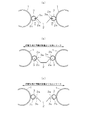
- connection part of the steel pipe sheet pile and steel sheet pile in one Embodiment of this invention is shown, (a) is a top view in case there is no construction error, (b) becomes the term space
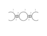
- (A)-(d) is a plan view showing a steel sheet pile connecting steel pipe sheet piles, (a) is a hat-shaped steel sheet pile, (b) is a linear steel sheet pile, (c) is In the case of a U-shaped steel sheet pile, (d) is the case of a Z-shaped steel sheet pile.
- (A)-(c) is a top view which shows the example at the time of providing a stopper member in the connection part of the steel sheet pile edge part, respectively.
- (A), (b) is the top view which showed the structure at the time of connecting and decentering a steel sheet pile with respect to a steel pipe sheet pile, (a) is a hat-shaped steel sheet pile, (b) is a linear steel plate.
- FIG. 3 is a perspective view of a beam structure. It is sectional drawing which showed the form of the conventional hat-shaped steel sheet pile. It is a top view which shows an example of the conventional steel pipe sheet pile wall.
- connection wall structure made of a conventional steel pipe sheet pile and a Z-shaped steel sheet pile (structure described in Non-Patent Document 1)
- (a) is a plan view of the connection wall structure
- (b) is a steel pipe sheet pile and It is a top view which shows the detail of the joint part of a Z-shaped steel sheet pile.
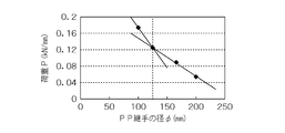
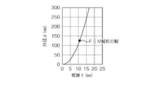
- 13 is a graph showing the relationship between the thickness t of a connecting member and the diameter ⁇ of the connecting member determined from the analysis by the cantilever model of FIG. It is the graph which showed the relationship between plate
- board thickness t and the load P by the FEM analysis result of a joint part when the outer diameter of a connection member is fixed to (PHI) 200mm and plate
- FIG. 1 shows the structure of a connecting portion between a steel pipe sheet pile and a steel sheet pile in one embodiment of the present invention
- (a) is a plan view when there is no construction error
- (b) is a plan interval of steel pipe sheet piles.
- (c) is a top view in the case where the term interval of a steel pipe sheet pile becomes wider than planned.
- the connecting wall structure of the present invention is a structure in which the steel pipe sheet pile 1 and the steel sheet pile 2 are connected, and a space for absorbing construction errors is provided in the connecting portion. That is, when connecting steel pipe sheet piles 1 placed at intervals with steel sheet piles 2 to form a connection wall structure, a connecting member 3 having slits 3a continuous in the longitudinal direction is provided on the side of the steel pipe sheet pile 1. By fitting the end portion of the steel sheet pile 2 to the slit portion 3a from the longitudinal direction, the connection member 3 and the end portion of the steel sheet pile 2 are connected, and the connection portion between the connection member 3 and the end portion of the steel sheet pile 2 is connected. Is provided with a predetermined play u for absorbing construction errors between the steel pipe sheet piles 1.
- connection wall structure of the steel pipe sheet pile 1 and the steel sheet pile 2 depending on the case, the steel pipe sheet pile 1 and the steel sheet pile 2 are prepared with separate construction machines, respectively, and the wall structure is constructed. In that case, in consideration of workability, a case where the steel sheet pile 1 is first driven and then the steel sheet pile 2 is driven or the opposite case is assumed.
- the steel pipe sheet pile 1 excellent in workability is obtained by sufficiently securing a space corresponding to the construction error between the steel pipe sheet piles 1 allowed at the connecting portion of the steel pipe sheet pile 1 and the steel sheet pile 2.
- the connection wall structure of the steel sheet pile 2 can be constructed. Even in this case, construction may be performed while aligning using a template for the purpose of construction with high construction accuracy.
- the connecting member of the steel pipe sheet pile 1 is, for example, a member (see FIG. 2 (b)) in which a steel pipe shown in FIG. 2 is combined with a member 3 (see FIG. 2 (a)) having a slit 3a and an angle 43, and a slit 43a is formed therebetween. And the like, as long as a sufficient space for securing the workability is secured.
- the steel sheet piles are also the hat-shaped steel sheet piles 2 (see FIG. 3A), the linear steel sheet piles 12 (see FIG. 3B), and the U-shaped steel sheet piles 22 (see FIG. 3C). ), Z-shaped steel sheet pile 32 (see FIG. 3 (d)), etc., as long as it can be fitted with a connecting member of a steel pipe sheet pile, the shape is not particularly limited.
- the hat-shaped steel sheet pile 2 having a flat section (flat portion 2a) in the arm portions beside the joint portions 2b and 2c shown in FIG.
- the steel sheet pile 22 it is easy to set play u for striking and shrinking at the time of steel pipe sheet pile construction, and the workability is also excellent.
- the inner diameter of the connecting member 3 is preferably 70 mm or more.
- a 900-width hat-shaped steel sheet pile includes joint portions 2b and 2c having a length of about 50 mm at both ends.
- the outer diameter is preferably 270 mm or less from the viewpoint of workability.
- FIG. 11 shows the result obtained by the above.
- the slope of the straight line changes before and after the outer diameter ⁇ is 125 mm. This indicates that the deformation or behavior when the load P is reached is different before and after the outer diameter of 125 mm.
- the steel sheet pile 2 yields mainly when ⁇ ⁇ 125 mm, and is mainly connected when ⁇ > 125 mm.
- the member 3 is deformed.
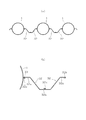
- the structure of the connecting portion is assumed to be a model in which a load P is applied to the tip of a cantilever (length L, depth direction length b, plate thickness t) as shown in FIG. .
- the length L indicates the length from the point where the connecting member 3 and the steel pipe main body of the steel pipe sheet pile 1 are fixed until the load is applied to the slit 3a of the connecting member 3. Then, for simplification, it was considered that this is equivalent to the outer diameter of the connecting member 3.
- the length L of the beam is replaced with the outer diameter ⁇ of the connecting member 3 from the equation (d) derived from the above cantilever beam model (that is, the following equation (2) ′), and this equation is shown in FIG.
- ⁇ outer diameter of the connecting member 3
- t thickness of the connecting member 3
- ⁇ y Yield stress of steel used for connecting member 3
- P y acting load that the steel sheet pile 2 yields
- b Length in the longitudinal direction in which the connecting member 3 and the steel sheet pile 2 are fitted.
- the actual steel pipe sheet pile 1 is considered to have some variation in diameter, slit width, welding or the like when the connecting member 3 is processed or attached. It is preferable that the thickness t of the connecting member 3 is equal to or greater than the thickness of the gradient change point, that is, a structure satisfying the formula (2).
- the length of the steel sheet pile member need not be the same as that of the steel pipe sheet pile 1 and may be shorter than the steel pipe sheet pile 1 and should be longer than the wall height so that the back soil does not flow out as a wall. It ’s fine.
- a water stop function when a water stop function is expected for the wall structure, it is generally performed to fill the connecting portion with a water stop material and perform a water stop treatment.
- a water stop function when the space of a connection part is narrow, since filling with a water stop material is difficult, it is not fully filled and there is a concern that a water stop function may not fully be exhibited.
- connection wall structure in which a space sufficient to fill the water-stopping material is filled in the connection portion between the steel pipe sheet pile 1 and the steel sheet pile 2, and construction related to water-stopping treatment. Costs and labor can be reduced.
- the connecting part may be excavated by a water jet method or the like, and mortar or water stop material may be filled inside. Therefore, it is desirable that the space of the connecting portion between the steel pipe sheet pile and the steel sheet pile be wide enough to be excavated by the water jet method.
- the connecting member 3 of the steel pipe sheet pile 1 there is a steel pipe type connecting member having a slit 3a of about 30 mm in a generally used steel pipe having a diameter of ⁇ 165.2 mm as shown in FIG. By applying this, even after the steel sheet pile 2 is connected, it becomes possible to sufficiently fill the water-stopping filler.
- the stopper member 4 is provided in the joint portion 2c (claw portion) of the steel sheet pile 2 to prevent the steel sheet pile 1 from being detached from the connection portion. be able to.
- the stopper member 4 at this time may be round steel, deformed bar steel, flat steel, etc., and other members may be used and are not particularly limited. Moreover, the stopper member 4 does not need to be provided over the longitudinal direction full length of the steel sheet pile 2, By making it discretely arranged, it can suppress the process cost, the distortion generation amount of the steel sheet pile 2 at the time of member installation, etc.
- FIG. 5 (a) shows a case where the hat-shaped steel sheet pile 2 is eccentrically connected to the steel pipe sheet pile 1, and the position of the steel sheet pile 2 is eccentric from the central axis of the steel pipe sheet pile 1 as a wall. Aligning the surface improves workability when installing a decorative panel on the front of the wall.
- FIG. 5B similarly shows a case where the straight steel sheet pile 12 is eccentrically connected to the steel pipe sheet pile 1.
Landscapes
- Engineering & Computer Science (AREA)
- General Engineering & Computer Science (AREA)
- Structural Engineering (AREA)
- Civil Engineering (AREA)
- Chemical & Material Sciences (AREA)
- Life Sciences & Earth Sciences (AREA)
- General Life Sciences & Earth Sciences (AREA)
- Mining & Mineral Resources (AREA)
- Paleontology (AREA)
- Composite Materials (AREA)
- Environmental & Geological Engineering (AREA)
- Ocean & Marine Engineering (AREA)
- Mechanical Engineering (AREA)
- Bulkheads Adapted To Foundation Construction (AREA)
- Revetment (AREA)
Abstract
Description

t:連結部材の板厚、
σy:連結部材に用いる鋼材の降伏応力、
Py:鋼矢板が降伏に至る作用荷重、
b:連結部材と鋼矢板とが嵌合されている長手方向の長さ

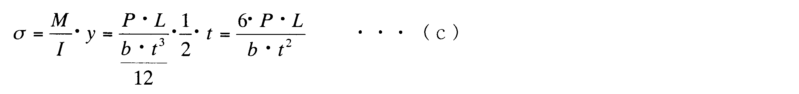
t:梁(連結部材3)の板厚、
y:中立軸から梁端までの距離=t/2


t:連結部材3の板厚、
σy:連結部材3に用いる鋼材の降伏応力、
Py:鋼矢板2が降伏に至る作用荷重、
b:連結部材3と鋼矢板2とが嵌合されている長手方向の長さ


2…鋼矢板(ハット形鋼矢板)、2a…平坦部、2b、2c…継手部、
3…連結部材、3a…スリット、
4…ストッパー部材、
12…直線形鋼矢板、12b…継手部、
22…U形鋼矢板、22b…継手部、
32…Z形鋼矢板、32b、32c…継手部、33…継手部材、
43…アングル、43a…スリット、
u…遊び
Claims (9)
- 間隔をおいて打設された鋼管矢板どうしを鋼矢板で連結してなる鋼管矢板と鋼矢板の連結壁構造において、前記鋼管矢板の側部に長手方向に連続するスリットを有する連結部材を設け、前記鋼矢板の端部を前記スリット部分に長手方向から嵌合することで、前記連結部材と鋼矢板の端部が連結されており、この連結部材と鋼矢板の端部との連結部に前記鋼管矢板どうしの施工誤差を吸収するための遊びを設けてあることを特徴とする鋼管矢板と鋼矢板の連結壁構造。
- 前記連結部材内に止水材が充填されていることを特徴とする請求項1記載の鋼管矢板と鋼矢板の連結壁構造。
- 前記鋼矢板の端部に前記スリットからの抜け出しを防止するためのストッパー部材が設けられていることを特徴とする請求項1または2記載の鋼管矢板と鋼矢板の連結壁構造。
- 前記連結部材は略円形であり、その外径Φ(mm)と板厚t(mm)との関係が式(1)の関係を満たすことを特徴とする請求項1、2または3記載の鋼管矢板と鋼矢板の連結壁構造。

- 前記連結部材の外径Φ(mm)と板厚t(mm)、さらに式(2)の条件を満たすことを特徴とする請求項4記載の鋼管矢板と鋼矢板の連結壁構造。

t:連結部材の板厚、
σy:連結部材に用いる鋼材の降伏応力、
Py:鋼矢板が降伏に至る作用荷重、
b:連結部材と鋼矢板とが嵌合されている長手方向の長さ - 前記鋼矢板は、軸方向と直角な断面における両端部に平坦な区間を有する鋼矢板であることを特徴とする請求項1~5のいずれか一項に記載の鋼管矢板と鋼矢板の連結壁構造。
- 前記鋼矢板は、U形鋼矢板であることを特徴とする請求項1~6のいずれか一項に記載の鋼管矢板と鋼矢板の連結壁構造。
- 前記鋼矢板の連結位置を前記鋼管矢板の中立軸より偏芯させてあることを特徴とする請求項1~7のいずれか一項に記載の鋼管矢板と鋼矢板の連結壁構造。
- 請求項1~8のいずれか一項に記載の鋼管矢板と鋼矢板の連結壁構造の構築方法であって、先に前記鋼管矢板を所定間隔をおいて打設し、後から前記鋼矢板を前記鋼管矢板どうしを連結する形で打設することを特徴とする鋼管矢板と鋼矢板の連結壁構造の構築方法。
Priority Applications (4)
| Application Number | Priority Date | Filing Date | Title |
|---|---|---|---|
| EP11765249.5A EP2554751A4 (en) | 2010-04-01 | 2011-01-12 | Connected wall structure consisting of steel pipe sheet piles and steel sheet pile, and method of constructing same |
| JP2011545518A JP4998646B2 (ja) | 2010-04-01 | 2011-01-12 | 鋼管矢板と鋼矢板の連結壁構造およびその構築方法 |
| CN201180005274.4A CN102713074B (zh) | 2010-04-01 | 2011-01-12 | 钢管板桩与钢板桩的连结壁结构及其构筑方法 |
| HK12112254.2A HK1171483A1 (en) | 2010-04-01 | 2012-11-28 | Connected wall structure consisting of steel pipe sheet piles and steel sheet pile, and method of constructing same |
Applications Claiming Priority (2)
| Application Number | Priority Date | Filing Date | Title |
|---|---|---|---|
| JP2010084944 | 2010-04-01 | ||
| JP2010-084944 | 2010-04-01 |
Publications (1)
| Publication Number | Publication Date |
|---|---|
| WO2011125347A1 true WO2011125347A1 (ja) | 2011-10-13 |
Family
ID=44762314
Family Applications (1)
| Application Number | Title | Priority Date | Filing Date |
|---|---|---|---|
| PCT/JP2011/050312 WO2011125347A1 (ja) | 2010-04-01 | 2011-01-12 | 鋼管矢板と鋼矢板の連結壁構造およびその構築方法 |
Country Status (7)
| Country | Link |
|---|---|
| EP (1) | EP2554751A4 (ja) |
| JP (1) | JP4998646B2 (ja) |
| CN (2) | CN104404915B (ja) |
| HK (1) | HK1171483A1 (ja) |
| MY (1) | MY164688A (ja) |
| TW (1) | TWI448608B (ja) |
| WO (1) | WO2011125347A1 (ja) |
Cited By (9)
| Publication number | Priority date | Publication date | Assignee | Title |
|---|---|---|---|---|
| JP2013112982A (ja) * | 2011-11-28 | 2013-06-10 | Nippon Steel & Sumitomo Metal | 壁体構造 |
| JP2016044502A (ja) * | 2014-08-26 | 2016-04-04 | 新日鐵住金株式会社 | 鋼管矢板の継手構造 |
| CN109610476A (zh) * | 2019-01-31 | 2019-04-12 | 上海宝钢工程咨询有限公司 | 钢管拉森板桩降水围护结构 |
| JP2019060222A (ja) * | 2017-09-22 | 2019-04-18 | トップマーク メカニカル イクイップメント リミテッドTop Mark Mechanical Equipment Limited | ケーシング又はパイルの連結システム |
| CN109736347A (zh) * | 2019-03-28 | 2019-05-10 | 中交第一航务工程局有限公司 | 一种水下基槽挡泥墙的施工工艺 |
| CN109763455A (zh) * | 2018-12-29 | 2019-05-17 | 中交水运规划设计院有限公司 | 透空式防波堤 |
| US11053655B2 (en) * | 2013-09-03 | 2021-07-06 | Lawrence S. Maxwell | Modular grid foundation |
| CN113789796A (zh) * | 2021-07-05 | 2021-12-14 | 长沙理工大学 | 一种大流速砂卵石区域的钢板桩围堰施工方法 |
| CN115419090A (zh) * | 2022-09-03 | 2022-12-02 | 无锡大诚建设有限公司 | 一种结构稳定的钢板桩围堰 |
Families Citing this family (5)
| Publication number | Priority date | Publication date | Assignee | Title |
|---|---|---|---|---|
| CN104120699B (zh) * | 2014-05-20 | 2016-04-27 | 中交第二航务工程局有限公司 | 钢板桩桶基人工岛护壁结构 |
| JP6690118B2 (ja) * | 2014-12-11 | 2020-04-28 | 日本製鉄株式会社 | 擁壁 |
| CN106836126A (zh) * | 2016-12-07 | 2017-06-13 | 孟展 | 新型水土保持防护管 |
| CN108149673B (zh) * | 2018-02-01 | 2024-02-20 | 刘德奇 | 混凝土桩及采用该混凝土桩拼接的连续防渗止水墙 |
| CN114837194A (zh) * | 2022-05-15 | 2022-08-02 | 中冶建工集团有限公司 | 一种提高pc组合桩稳定性的施工方法 |
Citations (6)
| Publication number | Priority date | Publication date | Assignee | Title |
|---|---|---|---|---|
| JPS57133919A (en) * | 1981-02-13 | 1982-08-18 | Kajima Corp | Construction of underground continuous wall |
| JPS5989120U (ja) * | 1982-12-02 | 1984-06-16 | 住友金属工業株式会社 | 鋼管と弧状鋼板とからなる護岸壁 |
| JPS6322915A (ja) * | 1986-05-09 | 1988-01-30 | シユトラバ−ク・バウ−アクチエンゲゼルシヤフト | 矢板壁用の管状支持シ−トパイル |
| JPH02213508A (ja) | 1989-02-14 | 1990-08-24 | Toa Harbor Works Co Ltd | 鋼管矢板と直線矢板を用いた防波堤 |
| JP2000136532A (ja) * | 1998-10-30 | 2000-05-16 | Nippon Steel Corp | 回転圧入矢板、及び回転圧入矢板の構築方法 |
| JP4231429B2 (ja) | 2003-02-19 | 2009-02-25 | 新日本製鐵株式会社 | 異形壁体構成部材の接続構造 |
Family Cites Families (7)
| Publication number | Priority date | Publication date | Assignee | Title |
|---|---|---|---|---|
| GB190914951A (en) * | 1909-06-26 | 1910-01-27 | Richard Henry Annison | Improvements in Locking Bars and Sheeting for Constructional Work. |
| JPH0757940B2 (ja) * | 1988-06-21 | 1995-06-21 | 川崎製鉄株式会社 | π形鋼矢板を用いた護岸工法 |
| CN2275119Y (zh) * | 1996-08-29 | 1998-02-25 | 湖南省公路桥梁建设总公司 | 一种企口钢管桩 |
| JP2002129550A (ja) * | 2000-10-20 | 2002-05-09 | Nkk Corp | 地中柱列壁用部材および地中柱列壁の施工方法 |
| JP4542290B2 (ja) * | 2001-08-31 | 2010-09-08 | 新日本製鐵株式会社 | 老朽化矢板護岸の修復護岸構造および修復工法 |
| CN1837512B (zh) * | 2006-04-07 | 2011-04-20 | 上海市政工程设计研究总院 | 一种钢板桩和钢管桩组合围堰及其制作方法 |
| CN201428137Y (zh) * | 2009-07-03 | 2010-03-24 | 东南大学 | 一种防水板桩围堰 |
-
2011
- 2011-01-12 EP EP11765249.5A patent/EP2554751A4/en not_active Withdrawn
- 2011-01-12 JP JP2011545518A patent/JP4998646B2/ja not_active Expired - Fee Related
- 2011-01-12 WO PCT/JP2011/050312 patent/WO2011125347A1/ja active Application Filing
- 2011-01-12 MY MYPI2012700454A patent/MY164688A/en unknown
- 2011-01-12 CN CN201410602239.6A patent/CN104404915B/zh active Active
- 2011-01-12 CN CN201180005274.4A patent/CN102713074B/zh not_active Expired - Fee Related
- 2011-02-10 TW TW100104403A patent/TWI448608B/zh not_active IP Right Cessation
-
2012
- 2012-11-28 HK HK12112254.2A patent/HK1171483A1/xx not_active IP Right Cessation
Patent Citations (6)
| Publication number | Priority date | Publication date | Assignee | Title |
|---|---|---|---|---|
| JPS57133919A (en) * | 1981-02-13 | 1982-08-18 | Kajima Corp | Construction of underground continuous wall |
| JPS5989120U (ja) * | 1982-12-02 | 1984-06-16 | 住友金属工業株式会社 | 鋼管と弧状鋼板とからなる護岸壁 |
| JPS6322915A (ja) * | 1986-05-09 | 1988-01-30 | シユトラバ−ク・バウ−アクチエンゲゼルシヤフト | 矢板壁用の管状支持シ−トパイル |
| JPH02213508A (ja) | 1989-02-14 | 1990-08-24 | Toa Harbor Works Co Ltd | 鋼管矢板と直線矢板を用いた防波堤 |
| JP2000136532A (ja) * | 1998-10-30 | 2000-05-16 | Nippon Steel Corp | 回転圧入矢板、及び回転圧入矢板の構築方法 |
| JP4231429B2 (ja) | 2003-02-19 | 2009-02-25 | 新日本製鐵株式会社 | 異形壁体構成部材の接続構造 |
Non-Patent Citations (2)
| Title |
|---|
| "Steel Sheet Piling General Catalogue 2008", 2008, pages: 34 |
| See also references of EP2554751A4 * |
Cited By (11)
| Publication number | Priority date | Publication date | Assignee | Title |
|---|---|---|---|---|
| JP2013112982A (ja) * | 2011-11-28 | 2013-06-10 | Nippon Steel & Sumitomo Metal | 壁体構造 |
| US11053655B2 (en) * | 2013-09-03 | 2021-07-06 | Lawrence S. Maxwell | Modular grid foundation |
| JP2016044502A (ja) * | 2014-08-26 | 2016-04-04 | 新日鐵住金株式会社 | 鋼管矢板の継手構造 |
| JP2019060222A (ja) * | 2017-09-22 | 2019-04-18 | トップマーク メカニカル イクイップメント リミテッドTop Mark Mechanical Equipment Limited | ケーシング又はパイルの連結システム |
| CN109763455A (zh) * | 2018-12-29 | 2019-05-17 | 中交水运规划设计院有限公司 | 透空式防波堤 |
| CN109763455B (zh) * | 2018-12-29 | 2024-04-09 | 中交水运规划设计院有限公司 | 透空式防波堤 |
| CN109610476A (zh) * | 2019-01-31 | 2019-04-12 | 上海宝钢工程咨询有限公司 | 钢管拉森板桩降水围护结构 |
| CN109610476B (zh) * | 2019-01-31 | 2024-05-17 | 上海宝钢工程咨询有限公司 | 钢管拉森板桩降水围护结构 |
| CN109736347A (zh) * | 2019-03-28 | 2019-05-10 | 中交第一航务工程局有限公司 | 一种水下基槽挡泥墙的施工工艺 |
| CN113789796A (zh) * | 2021-07-05 | 2021-12-14 | 长沙理工大学 | 一种大流速砂卵石区域的钢板桩围堰施工方法 |
| CN115419090A (zh) * | 2022-09-03 | 2022-12-02 | 无锡大诚建设有限公司 | 一种结构稳定的钢板桩围堰 |
Also Published As
| Publication number | Publication date |
|---|---|
| CN102713074A (zh) | 2012-10-03 |
| HK1171483A1 (en) | 2013-03-28 |
| CN104404915B (zh) | 2016-01-20 |
| JPWO2011125347A1 (ja) | 2013-07-08 |
| MY164688A (en) | 2018-01-30 |
| EP2554751A1 (en) | 2013-02-06 |
| TWI448608B (zh) | 2014-08-11 |
| TW201139792A (en) | 2011-11-16 |
| JP4998646B2 (ja) | 2012-08-15 |
| CN102713074B (zh) | 2015-03-25 |
| EP2554751A4 (en) | 2017-01-11 |
| CN104404915A (zh) | 2015-03-11 |
Similar Documents
| Publication | Publication Date | Title |
|---|---|---|
| JP4998646B2 (ja) | 鋼管矢板と鋼矢板の連結壁構造およびその構築方法 | |
| JP5347898B2 (ja) | 既設矢板岸壁の補強構造及び方法 | |
| JP2012007325A (ja) | 鋼管矢板壁構造 | |
| JP2008231799A (ja) | 免震構造 | |
| JP4851881B2 (ja) | 盛土構造物及び盛土構造物の補強方法 | |
| JP2016199861A (ja) | 杭基礎構造 | |
| JP6606911B2 (ja) | 山留め壁の支持構造および山留め壁の支持工法 | |
| JP2011111872A (ja) | 鋼管矢板の継手構造および鋼管矢板基礎 | |
| JP2014051820A (ja) | 組合せ鋼製壁 | |
| JP5637657B2 (ja) | 土留壁及びその補強方法 | |
| JP2014020129A (ja) | 鋼矢板及び鋼矢板壁体 | |
| JP2018119336A (ja) | 盛土の補強構造 | |
| JP6201929B2 (ja) | 橋台の洗掘防止構造 | |
| JP6070118B2 (ja) | 土留壁構造、土留壁構造の構築方法 | |
| JP5037387B2 (ja) | 土留壁の構築方法 | |
| JP4830589B2 (ja) | 芯材、ソイルセメント壁、ソイルセメント壁杭、ソイルセメント壁の構築方法 | |
| JP2013199746A (ja) | 土留壁 | |
| JP5633524B2 (ja) | 鋼矢板地下壁構造 | |
| JP6477586B2 (ja) | 鋼矢板壁 | |
| JP6536895B2 (ja) | 補強盛土一体橋梁におけるコンクリート壁構造および施工方法 | |
| JP4724680B2 (ja) | 柱脚構造 | |
| JP6763221B2 (ja) | 盛土の補強構造 | |
| JP5825232B2 (ja) | 組合せ鋼製壁および組合せ鋼製壁の設計方法 | |
| JP6515290B2 (ja) | 耐震岸壁構造 | |
| JP7551456B2 (ja) | 土留め構造の構築方法 |
Legal Events
| Date | Code | Title | Description |
|---|---|---|---|
| WWE | Wipo information: entry into national phase |
Ref document number: 201180005274.4 Country of ref document: CN |
|
| WWE | Wipo information: entry into national phase |
Ref document number: 2011545518 Country of ref document: JP |
|
| 121 | Ep: the epo has been informed by wipo that ep was designated in this application |
Ref document number: 11765249 Country of ref document: EP Kind code of ref document: A1 |
|
| WWE | Wipo information: entry into national phase |
Ref document number: 4254/DELNP/2012 Country of ref document: IN |
|
| WWE | Wipo information: entry into national phase |
Ref document number: 2011765249 Country of ref document: EP |
|
| NENP | Non-entry into the national phase |
Ref country code: DE |