WO2011122213A1 - アンテナの取付具 - Google Patents
アンテナの取付具 Download PDFInfo
- Publication number
- WO2011122213A1 WO2011122213A1 PCT/JP2011/054703 JP2011054703W WO2011122213A1 WO 2011122213 A1 WO2011122213 A1 WO 2011122213A1 JP 2011054703 W JP2011054703 W JP 2011054703W WO 2011122213 A1 WO2011122213 A1 WO 2011122213A1
- Authority
- WO
- WIPO (PCT)
- Prior art keywords
- antenna
- fixture
- protruding
- roof
- washer
- Prior art date
- Legal status (The legal status is an assumption and is not a legal conclusion. Google has not performed a legal analysis and makes no representation as to the accuracy of the status listed.)
- Ceased
Links
Images


Classifications
-
- H—ELECTRICITY
- H01—ELECTRIC ELEMENTS
- H01Q—ANTENNAS, i.e. RADIO AERIALS
- H01Q1/00—Details of, or arrangements associated with, antennas
- H01Q1/27—Adaptation for use in or on movable bodies
- H01Q1/32—Adaptation for use in or on road or rail vehicles
- H01Q1/325—Adaptation for use in or on road or rail vehicles characterised by the location of the antenna on the vehicle
- H01Q1/3275—Adaptation for use in or on road or rail vehicles characterised by the location of the antenna on the vehicle mounted on a horizontal surface of the vehicle, e.g. on roof, hood, trunk
-
- H—ELECTRICITY
- H01—ELECTRIC ELEMENTS
- H01Q—ANTENNAS, i.e. RADIO AERIALS
- H01Q1/00—Details of, or arrangements associated with, antennas
- H01Q1/12—Supports; Mounting means
- H01Q1/1207—Supports; Mounting means for fastening a rigid aerial element
- H01Q1/1214—Supports; Mounting means for fastening a rigid aerial element through a wall
Definitions
- the present invention relates to an antenna attachment for fixing a vehicle antenna to a vehicle body panel having a curved surface.
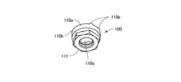
- FIGS. 20 is a perspective view seen from above showing the configuration of the fixture 100
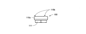
- FIG. 21 is a perspective view seen from below showing the configuration of the fixture 100
- FIG. 22 is a top view showing the configuration of the fixture 100
- FIG. 23 is a front view showing the configuration of the fixture 100.
- a plurality of triangular protruding pieces 110b are formed at the upper end of a washer portion 110a having a U-shaped cross section and a cylindrical shape.
- a nut portion 111 is rotatably fixed under the washer portion 110a.
- a ring-shaped protruding portion is formed from the upper surface of the hexagonal nut portion 111, and this ring-shaped protruding portion is inserted into the insertion hole 110c from below the washer portion 110a, thereby expanding the ring-shaped protruding portion. It is caulked to be calibrated. As a result, the ring-shaped projecting portion whose diameter has been increased engages with the inner narrowed portion formed on the lower surface of the washer portion 110a, and the nut portion 111 is rotatably fixed under the washer portion 110a. Become so.
- This fixture 100 is used for fixing a vehicle antenna on, for example, a vehicle roof.
- a protruding screw portion is formed protruding downward from the lower surface of the antenna base provided at the lower portion of the vehicle antenna.
- a mounting hole through which the protruding screw portion is inserted is formed in the roof, and the vehicle antenna is placed on the roof while the protruding screw portion is inserted into the mounting hole. Then, the fixture 100 is screwed from the inside of the vehicle to the protruding screw portion that is inserted into the mounting hole and protrudes to the inside of the vehicle.
- the four protruding pieces 110b which are formed in the triangular shape at the upper end of the washer portion 110a, bite into the inside of the vehicle body.
- the antenna base of the vehicle antenna is reliably grounded to the vehicle body via the fixture 100.
- an object of the present invention is to provide an antenna attachment that does not wobble even when a shark fin type vehicle antenna is attached to a vehicle body panel having a curved surface.
- the antenna mounting tool of the present invention is inserted from one side into a mounting hole formed in the vehicle panel, and is screwed from the opposite side of the vehicle panel to a protruding screw portion in which a screw is formed on the outer peripheral surface of the antenna body.
- the antenna mounting device has a U-shaped cross-sectional shape in which a plurality of protruding pieces, each having a sharp tip so as to bite into the vehicle panel, are formed at the upper end, and protrudes substantially from the center.
- a flat base plate having a plurality of protruding pieces formed on the outer edge so as to bite into the vehicle panel, and a washer portion
- a nut portion rotatably fixed to the lower portion and screwed to the screw portion formed on the outer peripheral surface of the protruding screw portion, and when the nut portion is fastened to the protruding screw portion,
- Multiple protruding pieces With serial bite on the vehicle panel, the plurality of protruding pieces are the most important feature that the bite to the vehicle panel.
- a plurality of projecting pieces whose tips are sharpened are formed on the outer edge of the flat base plate, and the nut portion that is rotatably fixed to the lower portion of the washer portion is used as the protruding screw portion. Since the plurality of protruding pieces and the plurality of protruding pieces bite into the vehicle panel when fastened, the shark fin-like antenna can be attached to the curved vehicle panel without wobbling.
- FIG. 6 is a cross-sectional view taken along line aa showing another configuration in which an antenna device including an antenna fixture according to the present invention is attached to a roof. It is sectional drawing which expands and partially shows the other structure which attached the antenna apparatus provided with the fixture of the antenna concerning this invention to the roof.
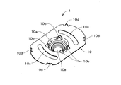
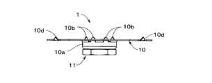
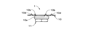
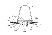
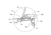
- FIG. 1 is a perspective view seen from above showing the configuration of the antenna fixture 1 according to the present invention
- FIG. 2 is a perspective view seen from below showing the configuration of the antenna fixture 1 according to the present invention
- FIG. 3 is a top view showing the configuration of the antenna fixture 1 according to the present invention
- FIG. 4 is a front view showing the configuration of the antenna fixture 1 according to the present invention
- FIG. 5 shows the antenna according to the present invention. It is a side view which shows the structure of the fixture 1 of.
- the antenna fixture 1 is formed by processing a metal plate, and includes a flat base plate 10, a washer portion 10 a formed on the base plate 10, The hexagonal metal nut portion 11 is rotatably fixed to the washer portion 10a.
- FIG. 6 is a perspective view showing the configuration of the base plate 10 according to the antenna fixture 1 of the present invention
- FIG. 7 is a front view showing the configuration of the base plate 10 according to the antenna fixture 1 of the present invention.
- the base plate 10 has a rectangular shape with a short side formed in an arc shape, and is pressed downward so as to protrude downward substantially in the center to form a washer portion 10a.
- the washer portion 10a has a U-shaped cross-section and is formed with an insertion hole 10e. The lower end of the insertion hole 10e is drawn inward, the inner diameter is narrowed, and the ring protrudes inward in a ring shape.
- the washer portion 10a From the upper end of the insertion hole 10e in the washer portion 10a, four triangularly protruding pieces 10b are formed so as to protrude upward.
- the plurality of projecting pieces 10 b are formed so as to project upward beyond the upper surface of the base plate 10.
- the plurality of protruding pieces 10b are formed by notching the boundary portion with the washer portion 10a in the base plate 10, and the washer portion 10a is held by the base plate 10 at the boundary portion excluding the notched portion. Yes. For this reason, the washer portion 10a is integrally formed with the base plate 10 with elasticity due to the notch.
- a pair of protruding pieces 10 d formed by cutting grooves on both sides are formed at a boundary portion with the long side.
- the plurality of projecting pieces 10 d are also formed to be bent upward from the upper surface of the base plate 10.
- two arc-shaped long holes 10c are formed in the base plate 10 around the washer portion 10a so as to be substantially parallel to the short side.
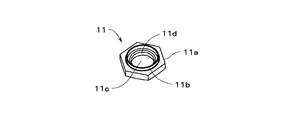
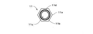
- FIG. 8 is a perspective view showing the configuration of the nut portion 11 according to the antenna fixture 1 of the present invention
- FIG. 9 is a top view showing the configuration of the nut portion 11 according to the antenna fixture 1 of the present invention
- FIG. 10 is a front view showing the configuration of the nut portion 11 according to the antenna fixture 1 of the present invention.
- the nut portion 11 is composed of a hexagonal hexagonal portion 11a in which a through hole 11c is formed, and a ring-shaped projecting portion 11b projects from the upper end of the through hole 11c on the upper surface of the hexagonal portion 11a.
- An internal thread 11d is formed on the inner peripheral surface of the through hole 11c in the hexagonal portion 11a.
- FIG. 11 shows an exploded view for assembling the antenna fixture 1 according to the embodiment of the present invention.
- the nut portion 11 is arranged below the base plate 10 so that the ring-shaped protruding portion 11 b becomes the upper surface.
- the ring-shaped protrusion part 11b of the nut part 11 is penetrated in the insertion hole 10e from the downward direction of the washer part 10a.
- the ring-shaped protrusion 11b is crimped so that the outer diameter of the ring-shaped protrusion 11b inserted through the insertion hole 10e is increased.
- the ring-shaped projecting portion 11b having an enlarged diameter engages with the portion of the washer portion 10a whose inner diameter is narrowed at the lower end and projects inwardly in a ring shape, so that the nut portion 11 does not come out of the insertion hole 10e. At the same time, it is rotatably fixed to the washer portion 10a.
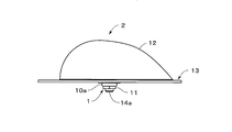
- FIGS. 12 is a side view showing an outline of the configuration of the antenna device 2 attached to the roof 13
- FIG. 13 is a top view showing the outline of the configuration of the antenna device 2 attached to the roof 13.
- the antenna device 2 includes a shark fin-shaped housing 12, an antenna portion is built in the housing 12, and a metal antenna base 14 is fixed so as to close the lower surface of the housing 12. Yes.
- a protruding screw portion 14a is formed to protrude downward.
- the antenna device 2 is disposed on the roof 13 by inserting the protruding screw portion 14 a into an attachment hole formed in the roof 13.
- the protruding screw portion 14a is exposed through the mounting hole and exposed inside the vehicle body, and the protruding screw portion 14a protruding inside the vehicle body is inserted into the insertion hole 10e of the fixture 1 inside the vehicle body and the nut portion 11 is screwed. To do.
- the four triangular pointed protrusions 10d formed on the outer edge of the base plate 10 bite into the inner surface of the roof 13
- Four triangularly protruding pieces 10b formed at the upper end of the washer portion 10a bite into the inner surface of the roof 13. This ensures that the antenna base 14 of the antenna device 2 is grounded to the vehicle body via the fixture 1.
- the long axis of the base plate 10 is arranged in a direction transverse to the traveling direction of the vehicle, and the roof 13 is sandwiched between the flat base plate 10 and the antenna base 14, so that the shark fin antenna device 2 is provided. Even if it is attached to the roof 13, wobbling can be prevented.
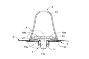
- FIGS. 14 is a front view showing details of the configuration of the antenna device 2 attached to the roof 13
- FIG. 15 is a front view showing details of the configuration of the antenna device 2 attached to the roof 13 in a sectional view.
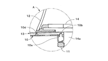
- 16 is a partially enlarged view showing the details of the configuration of the antenna device 2 attached to the roof 13 in a sectional view.
- the lower surface of the shark fin-like casing 12 of the antenna device 2 is closed by the antenna base 14, and a protruding screw portion 14 a protrudes downward from substantially the center of the lower surface of the antenna base 14. Has been.
- the width of the housing 12 in the antenna device 2 and the interval between the protruding pieces 10d formed on both sides of the base plate 10 are substantially the same, and the antenna device 2 is attached to the roof 13 without wobbling.
- the notch for forming the protrusion piece 10b is formed in several places in the boundary part of the washer part 10a and the base board 10, when the nut part 11 is fastened by the protrusion screw
- the base plate 10 is elastically pressed against the roof 13.
- the base plate 10 itself is also elastically deformed by the action of the two long holes 10c, the antenna device 2 can be securely attached to the roof 13 by the fixture 1 even if the roof 13 is curved. .
- FIGS. 19 shows. 17 is a front view showing details of the configuration of the antenna device 2 attached to the roof 13, and FIG. 18 is a front view showing details of the configuration of the antenna device 2 attached to the roof 13 in a sectional view. 19 is a partially enlarged view showing the details of the configuration of the antenna device 2 attached to the roof 13 in a cross-sectional view.
- a plurality of reinforcing members 13 a are provided inside the roof 13 of the antenna device 2, and the fixture 1 is disposed so as to straddle the reinforcing members 13 a. That is, when the nut portion 11 of the fixture 1 is fastened to the protruding screw portion 14a using a spanner or the like, the plurality of protruding pieces 10b formed on the washer portion 10a bite into the back surface of the roof 13. However, the plurality of protruding pieces 10d formed on the outer edge of the base plate 10 ride on the reinforcing member 13a and bite into the reinforcing member 13a.
- the base plate 10 itself is elastically deformed by the action of the two long holes 10c even if the plurality of protruding pieces 10d are placed on the reinforcing member 13a, so that the antenna device 2 is reliably reinforced by the fixture 1. It can be attached to the roof 13 provided with the member 13a. Moreover, since the notch for forming the protrusion piece 10b is formed in multiple places in the boundary part of the washer part 10a and the base board 10, when the nut part 11 is fastened by the protrusion screw part 14a, Further, the base plate 10 is elastically pressed against the roof 13. Thereby, the antenna apparatus 2 comes to be attached to the roof 13 provided with the reinforcing member 13a without wobbling.
- the base plate 10 is rectangular, but may be rectangular, elliptical, or circular.
- the number of protrusion pieces provided on the outer edge of the base plate 10 is not limited to four, but may be three, or five or more.
- the number of protruding pieces 10b provided at the upper end of the washer portion 10a is not limited to four, but may be three, or five or more.
- the number of the long holes 10c formed in the base plate 10 is not limited to two, but may be four or more.
- the antenna device has a shark fin shape
- the shape is not limited to this, and any shape can be used as long as the antenna device has a casing with a length of about 160 to 220 mm and a height of about 60 to 70 mm.
- the antenna device can be attached to the vehicle body panel without wobbling.
Landscapes
- Engineering & Computer Science (AREA)
- Remote Sensing (AREA)
- Support Of Aerials (AREA)
Priority Applications (3)
| Application Number | Priority Date | Filing Date | Title |
|---|---|---|---|
| EP11762453.6A EP2555316A4 (en) | 2010-03-29 | 2011-03-02 | ANTENNA CRAB |
| CN2011800035575A CN102484309A (zh) | 2010-03-29 | 2011-03-02 | 天线夹具 |
| US13/632,446 US20130026331A1 (en) | 2010-03-29 | 2012-10-01 | Mounting bracket for antenna |
Applications Claiming Priority (2)
| Application Number | Priority Date | Filing Date | Title |
|---|---|---|---|
| JP2010-075288 | 2010-03-29 | ||
| JP2010075288A JP5448969B2 (ja) | 2010-03-29 | 2010-03-29 | アンテナの取付具 |
Related Child Applications (1)
| Application Number | Title | Priority Date | Filing Date |
|---|---|---|---|
| US13/632,446 Continuation US20130026331A1 (en) | 2010-03-29 | 2012-10-01 | Mounting bracket for antenna |
Publications (1)
| Publication Number | Publication Date |
|---|---|
| WO2011122213A1 true WO2011122213A1 (ja) | 2011-10-06 |
Family
ID=44711942
Family Applications (1)
| Application Number | Title | Priority Date | Filing Date |
|---|---|---|---|
| PCT/JP2011/054703 Ceased WO2011122213A1 (ja) | 2010-03-29 | 2011-03-02 | アンテナの取付具 |
Country Status (5)
| Country | Link |
|---|---|
| US (1) | US20130026331A1 (enExample) |
| EP (1) | EP2555316A4 (enExample) |
| JP (1) | JP5448969B2 (enExample) |
| CN (1) | CN102484309A (enExample) |
| WO (1) | WO2011122213A1 (enExample) |
Cited By (1)
| Publication number | Priority date | Publication date | Assignee | Title |
|---|---|---|---|---|
| WO2022210491A1 (ja) * | 2021-03-29 | 2022-10-06 | 原田工業株式会社 | アンテナ取付構造及びアンテナ装置 |
Families Citing this family (7)
| Publication number | Priority date | Publication date | Assignee | Title |
|---|---|---|---|---|
| WO2013108805A1 (ja) * | 2012-01-20 | 2013-07-25 | 矢崎総業株式会社 | アース接続構造及びその製造方法 |
| WO2016196889A1 (en) * | 2015-06-04 | 2016-12-08 | Armstrong Aerospace | Equipment mounting device |
| DE102017118478B4 (de) * | 2016-08-15 | 2023-09-07 | Hirschmann Car Communication Gmbh | Verrastung einer Dachantenne eines Fahrzeuges mittels eines Drehkreuzes |
| FR3061752A1 (fr) * | 2017-01-10 | 2018-07-13 | Cobra Europe | Insert taraude pour l'assemblage par moyen de jonction de bandes transporteuses et jonction |
| JP6818620B2 (ja) * | 2017-04-11 | 2021-01-20 | 株式会社ヨコオ | アンテナ取付装置、アンテナ装置の取付方法 |
| DE102018121188B4 (de) * | 2017-09-05 | 2025-05-08 | Hirschmann Car Communication Gmbh | Befestigung einer modulartig ausgebildeten Dachantenne |
| US12374785B2 (en) | 2021-09-17 | 2025-07-29 | Hirschmann Car Communication Inc. | Antenna mount assembly |
Citations (4)
| Publication number | Priority date | Publication date | Assignee | Title |
|---|---|---|---|---|
| JPS63165906U (enExample) * | 1987-04-20 | 1988-10-28 | ||
| JPH03113515U (enExample) * | 1990-03-06 | 1991-11-20 | ||
| JP2001036315A (ja) | 1999-07-22 | 2001-02-09 | Nippon Antenna Co Ltd | 自動車用アンテナ |
| JP2004023227A (ja) | 2002-06-13 | 2004-01-22 | Nippon Antenna Co Ltd | アンテナ取付ナット |
Family Cites Families (30)
| Publication number | Priority date | Publication date | Assignee | Title |
|---|---|---|---|---|
| US1796610A (en) * | 1926-12-01 | 1931-03-17 | Modler Johann | Roller bearing |
| US2304155A (en) * | 1941-04-10 | 1942-12-08 | Dyball Ernest George | Joint washer |
| US2953630A (en) * | 1958-06-24 | 1960-09-20 | Ward Products Corp | Antenna mounting |
| US3076936A (en) * | 1960-03-08 | 1963-02-05 | Automatic Radio Mfg Co | Means and method for securing a radio to a cab roof |
| DE1236035B (de) * | 1962-04-24 | 1967-03-09 | Hirschmann Radiotechnik | Nichtversenkbare Stab- oder Teleskopantenne fuer Kraftfahrzeuge |
| US3315720A (en) * | 1965-10-20 | 1967-04-25 | Illinois Tool Works | Non-crazing spring washer |
| US4431332A (en) * | 1982-09-30 | 1984-02-14 | Autotenna | Mounting structure |
| US5267423A (en) * | 1987-08-03 | 1993-12-07 | Giannuzzi Louis | Self-drilling anchor and bearing plate assembly |
| FR2623021B1 (fr) * | 1987-11-10 | 1990-02-16 | Pizon Ernest | Dispositif de liaison a la masse pour antenne receptrice ou emettrice d'ondes electro-magnetiques,notamment pour auto-radio et antenne equipee d'un tel dispositif de liaison a la masse |
| US4958452A (en) * | 1989-09-27 | 1990-09-25 | Zoecon Corporation | Animal identification ear tag assembly |
| FR2655481B1 (fr) * | 1989-12-04 | 1992-07-24 | De Bellomayre Michel | Dispositif pour faciliter le montage des antennes radio et ameliorer leur raccordement de masse. |
| IT224595Z2 (it) * | 1991-04-29 | 1996-05-29 | Elemento di contatto e di fissaggio rapido per cavi coassiali per an- tenne di autoradio. | |
| US5207535A (en) * | 1991-10-30 | 1993-05-04 | Saab Thomas L | Push-on gripper plate for use with rock bolts |
| US5599131A (en) * | 1994-05-23 | 1997-02-04 | Flexible Steel Lacing Company | Plate fastener with bolts preassembled |
| US5831579A (en) * | 1997-04-15 | 1998-11-03 | Ericsson, Inc. | Latch mechanism for mobile communication devices |
| US7128511B2 (en) * | 1998-10-30 | 2006-10-31 | John Hewgill | Fastener |
| US6345925B1 (en) * | 1999-09-13 | 2002-02-12 | Flexible Steel Lacing Company | Bolt for conveyor belt fastener |
| JP3425108B2 (ja) * | 1999-12-07 | 2003-07-07 | 日本アンテナ株式会社 | アンテナ取付ナット |
| US6683570B2 (en) * | 2001-03-29 | 2004-01-27 | Tyco Electronics Corporation | Compact multi-band antenna |
| US7004666B2 (en) * | 2001-10-09 | 2006-02-28 | Tyco Electronics Corporation | Quick-attach automotive antenna mounting assembly |
| JP3827159B2 (ja) * | 2003-01-23 | 2006-09-27 | 株式会社ヨコオ | 車載用アンテナ装置 |
| JP3859630B2 (ja) * | 2003-09-26 | 2006-12-20 | クラリオン株式会社 | 自動車用アンテナ |
| JP4680776B2 (ja) * | 2003-11-25 | 2011-05-11 | 原田工業株式会社 | 車両用ルーフアンテナ取付け装置 |
| DE102005044611A1 (de) * | 2004-09-28 | 2006-03-30 | Hirschmann Car Communication Gmbh | Antenne und Verfahren zur Befestigung einer Antenne an einem Fahrzeug mittels Klemmkraft, erzeugt vorzugsweise durch einen Schiebvorgang |
| JP4297861B2 (ja) * | 2004-10-18 | 2009-07-15 | 株式会社ヨコオ | アンテナベース取付構造 |
| JP2006345245A (ja) * | 2005-06-09 | 2006-12-21 | Yokowo Co Ltd | アンテナ取付装置 |
| JP4687880B2 (ja) * | 2005-06-28 | 2011-05-25 | ミツミ電機株式会社 | 複合アンテナ装置 |
| US7077263B1 (en) * | 2005-10-11 | 2006-07-18 | Richardson Thomas W | Belt fastener assembly |
| US7679572B2 (en) * | 2007-09-26 | 2010-03-16 | Harada Industry Of America, Inc. | Body mount for a vehicle antenna |
| US8070404B1 (en) * | 2008-11-06 | 2011-12-06 | Middle Atlantic Products, Inc. | Bonding fastener assembly for electrical grounding |
-
2010
- 2010-03-29 JP JP2010075288A patent/JP5448969B2/ja not_active Expired - Fee Related
-
2011
- 2011-03-02 CN CN2011800035575A patent/CN102484309A/zh active Pending
- 2011-03-02 EP EP11762453.6A patent/EP2555316A4/en not_active Withdrawn
- 2011-03-02 WO PCT/JP2011/054703 patent/WO2011122213A1/ja not_active Ceased
-
2012
- 2012-10-01 US US13/632,446 patent/US20130026331A1/en not_active Abandoned
Patent Citations (4)
| Publication number | Priority date | Publication date | Assignee | Title |
|---|---|---|---|---|
| JPS63165906U (enExample) * | 1987-04-20 | 1988-10-28 | ||
| JPH03113515U (enExample) * | 1990-03-06 | 1991-11-20 | ||
| JP2001036315A (ja) | 1999-07-22 | 2001-02-09 | Nippon Antenna Co Ltd | 自動車用アンテナ |
| JP2004023227A (ja) | 2002-06-13 | 2004-01-22 | Nippon Antenna Co Ltd | アンテナ取付ナット |
Non-Patent Citations (1)
| Title |
|---|
| See also references of EP2555316A4 * |
Cited By (2)
| Publication number | Priority date | Publication date | Assignee | Title |
|---|---|---|---|---|
| WO2022210491A1 (ja) * | 2021-03-29 | 2022-10-06 | 原田工業株式会社 | アンテナ取付構造及びアンテナ装置 |
| JP7593631B2 (ja) | 2021-03-29 | 2024-12-03 | 原田工業株式会社 | アンテナ取付構造及びアンテナ装置 |
Also Published As
| Publication number | Publication date |
|---|---|
| JP5448969B2 (ja) | 2014-03-19 |
| EP2555316A1 (en) | 2013-02-06 |
| JP2011211363A (ja) | 2011-10-20 |
| EP2555316A4 (en) | 2014-06-18 |
| CN102484309A (zh) | 2012-05-30 |
| US20130026331A1 (en) | 2013-01-31 |
Similar Documents
| Publication | Publication Date | Title |
|---|---|---|
| JP5448969B2 (ja) | アンテナの取付具 | |
| US8690194B1 (en) | Flexible metal conduit to electrical metallic tubing/rigid conduit transition coupler | |
| US20140061412A1 (en) | Bracket with nut | |
| KR20140021607A (ko) | 셀프-센터링 케이지 너트 | |
| US10830267B2 (en) | Device for mounting an attachment part to a carrier part | |
| US10374339B2 (en) | Battery terminal | |
| JP2015534195A5 (enExample) | ||
| BRPI0614624A2 (pt) | plugue com mola de retenção para um contato de terra | |
| US10099601B2 (en) | Vehicle lamp | |
| JP2017110335A (ja) | 壁面の取付ユニット | |
| JP5570342B2 (ja) | ルアー | |
| JP3171082U (ja) | 固着ボルト | |
| JP2016169819A (ja) | リターンチューブの取付部品、ボールねじ | |
| JP2007048566A (ja) | 締結具及びこの締結具を用いたコネクタ | |
| JP6243789B2 (ja) | クリップの固定構造 | |
| KR102123409B1 (ko) | 접지단자 | |
| WO2014112319A1 (ja) | バスバー取付構造体およびバスバー取付構造体の製造方法 | |
| JP2012231802A (ja) | ルアー | |
| JP3138316U (ja) | 内装パネルの孔塞ぎ具 | |
| JPWO2019093126A1 (ja) | 取付位置調整部材及びスイッチ装置 | |
| JP2009156303A (ja) | 雌ねじが形成された部材に繰り返し容易に着脱できるクリップ | |
| JP2006153154A (ja) | 取着体およびビス固定ナット | |
| JP6636365B2 (ja) | 支持金具ユニット | |
| JP2023119352A (ja) | 取付装置およびそれを備えたアンテナ装置 | |
| KR20130118172A (ko) | 판형 나사 및 판형 나사용 드라이버 |
Legal Events
| Date | Code | Title | Description |
|---|---|---|---|
| WWE | Wipo information: entry into national phase |
Ref document number: 201180003557.5 Country of ref document: CN |
|
| 121 | Ep: the epo has been informed by wipo that ep was designated in this application |
Ref document number: 11762453 Country of ref document: EP Kind code of ref document: A1 |
|
| NENP | Non-entry into the national phase |
Ref country code: DE |
|
| WWE | Wipo information: entry into national phase |
Ref document number: 2011762453 Country of ref document: EP |