WO2011122105A1 - 電動機駆動装置の制御装置 - Google Patents
電動機駆動装置の制御装置 Download PDFInfo
- Publication number
- WO2011122105A1 WO2011122105A1 PCT/JP2011/052400 JP2011052400W WO2011122105A1 WO 2011122105 A1 WO2011122105 A1 WO 2011122105A1 JP 2011052400 W JP2011052400 W JP 2011052400W WO 2011122105 A1 WO2011122105 A1 WO 2011122105A1
- Authority
- WO
- WIPO (PCT)
- Prior art keywords
- control
- field
- voltage
- command value
- value
- Prior art date
- Legal status (The legal status is an assumption and is not a legal conclusion. Google has not performed a legal analysis and makes no representation as to the accuracy of the status listed.)
- Ceased
Links
Images




Classifications
-
- H—ELECTRICITY
- H02—GENERATION; CONVERSION OR DISTRIBUTION OF ELECTRIC POWER
- H02P—CONTROL OR REGULATION OF ELECTRIC MOTORS, ELECTRIC GENERATORS OR DYNAMO-ELECTRIC CONVERTERS; CONTROLLING TRANSFORMERS, REACTORS OR CHOKE COILS
- H02P27/00—Arrangements or methods for the control of AC motors characterised by the kind of supply voltage
- H02P27/04—Arrangements or methods for the control of AC motors characterised by the kind of supply voltage using variable-frequency supply voltage, e.g. inverter or converter supply voltage
- H02P27/06—Arrangements or methods for the control of AC motors characterised by the kind of supply voltage using variable-frequency supply voltage, e.g. inverter or converter supply voltage using DC to AC converters or inverters
- H02P27/08—Arrangements or methods for the control of AC motors characterised by the kind of supply voltage using variable-frequency supply voltage, e.g. inverter or converter supply voltage using DC to AC converters or inverters with pulse width modulation
-
- H—ELECTRICITY
- H02—GENERATION; CONVERSION OR DISTRIBUTION OF ELECTRIC POWER
- H02P—CONTROL OR REGULATION OF ELECTRIC MOTORS, ELECTRIC GENERATORS OR DYNAMO-ELECTRIC CONVERTERS; CONTROLLING TRANSFORMERS, REACTORS OR CHOKE COILS
- H02P21/00—Arrangements or methods for the control of electric machines by vector control, e.g. by control of field orientation
- H02P21/0003—Control strategies in general, e.g. linear type, e.g. P, PI, PID, using robust control
- H02P21/0021—Control strategies in general, e.g. linear type, e.g. P, PI, PID, using robust control using different modes of control depending on a parameter, e.g. the speed
-
- H—ELECTRICITY
- H02—GENERATION; CONVERSION OR DISTRIBUTION OF ELECTRIC POWER
- H02P—CONTROL OR REGULATION OF ELECTRIC MOTORS, ELECTRIC GENERATORS OR DYNAMO-ELECTRIC CONVERTERS; CONTROLLING TRANSFORMERS, REACTORS OR CHOKE COILS
- H02P21/00—Arrangements or methods for the control of electric machines by vector control, e.g. by control of field orientation
- H02P21/0085—Arrangements or methods for the control of electric machines by vector control, e.g. by control of field orientation specially adapted for high speeds, e.g. above nominal speed
- H02P21/0089—Arrangements or methods for the control of electric machines by vector control, e.g. by control of field orientation specially adapted for high speeds, e.g. above nominal speed using field weakening
-
- H—ELECTRICITY
- H02—GENERATION; CONVERSION OR DISTRIBUTION OF ELECTRIC POWER
- H02P—CONTROL OR REGULATION OF ELECTRIC MOTORS, ELECTRIC GENERATORS OR DYNAMO-ELECTRIC CONVERTERS; CONTROLLING TRANSFORMERS, REACTORS OR CHOKE COILS
- H02P21/00—Arrangements or methods for the control of electric machines by vector control, e.g. by control of field orientation
- H02P21/06—Rotor flux based control involving the use of rotor position or rotor speed sensors
Definitions
- Patent Document 1 discloses an electric motor that shifts from sinusoidal PWM control to overmodulation PWM control and further to rectangular wave control as the rotational speed of the motor increases and the induced voltage increases.
- the technology of the control device of the driving device is described.
- the modulation rate which is the ratio of the effective value of the fundamental wave component of the AC voltage waveform to the DC power supply voltage (system voltage)
- the upper limit of the modulation rate is 0.61 in the sinusoidal PWM control.
- overmodulation PWM control can increase the modulation rate to a range of 0.61 to 0.78
- rectangular wave control has a maximum modulation rate of 0.78.
- the loss of the AC motor and the motor driving device when the normal field / pulse width modulation control mode for executing the pulse width modulation control together with the normal field control is executed is defined as a normal time loss, and the rectangular shape is set together with the strong field control.
- the strong field / rectangular wave control mode for executing the wave control is executed, the loss of the AC motor and the motor driving device is set as the strong field time loss, and the strong field time loss is smaller than the normal time loss.
- the upper limit in the direction of increasing the field magnetic flux in the field adjustment command value range is the adjustment command threshold value.
- the rotation speed threshold value is determined based on the target torque and the DC voltage. According to this configuration, it is possible to set an appropriate rotation speed threshold value according to the target torque and the DC voltage.
- the voltage command value can be appropriately determined by current feedback control based on the deviation between the actual current value detected by the current sensor or the like and the current command value after adjustment by the field adjustment command value. it can.
- Each of the switching elements E1 to E6 performs an on / off operation according to the switching control signals S1 to S6 output from the control device 2.
- the inverter 6 converts the DC voltage Vdc into an AC voltage and supplies it to the electric motor 4 to cause the electric motor 4 to output a torque corresponding to the target torque TM.
- each of the switching elements E1 to E6 performs a switching operation according to PWM control or rectangular wave control, which will be described later, according to the switching control signals S1 to S6.
- the switching control signals S1 to S6 are gate drive signals that drive the gates of the switching elements E1 to E6.
- the overmodulation PWM control is a PWM control in which the amplitude of the AC voltage waveforms Vu, Vv, and Vw exceeds the amplitude of the carrier waveform (triangular wave).
- overmodulation PWM control the waveform of the fundamental wave component of the output voltage waveform of the inverter 6 is distorted by making the duty ratio of each pulse large on the peak side of the fundamental wave component and smaller on the valley side than in normal PWM control, Control is performed so that the amplitude is larger than that of the normal PWM control.
- the modulation factor M can be changed in the range of “0.707 to 0.78”.
- the induced voltage of the electric motor 4 increases as the rotational speed ⁇ increases, and the AC voltage (hereinafter referred to as “required voltage”) required to drive the electric motor 4 also increases.
- the necessary voltage exceeds the maximum AC voltage that can be output from the inverter 6 by converting the DC voltage Vdc at that time (hereinafter referred to as “maximum output voltage”)
- maximum output voltage the maximum AC voltage that can be output from the inverter 6 by converting the DC voltage Vdc at that time
- the electric motor 4 cannot be appropriately controlled. Therefore, the field weakening / rectangular wave control mode A5 is executed in the region on the higher rotation side than the curve L1 where the modulation factor M representing the required voltage of the motor 4 with respect to the maximum output voltage based on the DC voltage Vdc reaches the maximum modulation factor Mmax.
- the necessary voltage and the maximum output voltage can be compared with each other as the effective value of the AC voltage.
- the strong field / rectangular wave control mode A3 for executing the rectangular wave control together with the strong field control is executed. To do. Further, in order to prevent the adjusted current command values Id and Iq from changing suddenly during the transition between the strong field / rectangular wave control mode A3 and the other modes, the strong field / PWM control mode A2 Is executed. Thereby, it is possible to suppress a sudden change and overshoot of the current flowing in the coil of the electric motor 4 and to suppress the vibration of the output torque of the electric motor 4 from occurring. If the normal field control is performed, the rectangular wave control can be performed while outputting the torque corresponding to the target torque TM to the electric motor 4 by executing the strong field control while the modulation factor M is lower than the maximum modulation factor Mmax. it can.
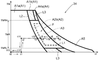
- a broken line that divides the strong field control region F is a region in which the strong field / PWM control mode A2 is executed when the rotation speed ⁇ or the target torque TM of the motor 4 changes at a predetermined change speed.
- 2 shows an example of a boundary where the strong field / rectangular wave control mode A3 is switched. The position of this boundary differs depending on the rotational speed ⁇ or the change speed of the target torque TM.
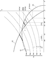
- “Iq1” which is the value of the q-axis current at the intersection is derived as the basic q-axis current command value Iqb.
- the control device 2 executes the normal field / PWM control mode A1.
- the d-axis current values (Id1, Id3, Id5) corresponding to the basic q-axis current command values Iqb (Iq1, Iq3, Iq5) obtained from the q-axis current command value map of FIG. 5 are the basic values shown in FIG. This coincides with the basic d-axis current command value Idb obtained using the d-axis current command value map. Therefore, the basic d-axis current command value Idb can be obtained from the map shown in FIG.
- the current control unit 24 performs a proportional-integral control calculation (PI control calculation) based on the d-axis current deviation ⁇ Id to derive a basic d-axis voltage command value Vzd, and also performs a proportional integration based on the q-axis current deviation ⁇ Iq.
- PI control calculation a proportional-integral control calculation based on the d-axis current deviation ⁇ Id to derive a basic d-axis voltage command value Vzd
- a control calculation is performed to derive a basic q-axis voltage command value Vzq.
- PID control calculation instead of these proportional integral control calculations.
- the d-axis voltage command value Vd and the q-axis voltage command value Vq are input to the two-phase / three-phase conversion unit 25.
- the magnetic pole position ⁇ detected by the rotation sensor 43 (see FIG. 1) is input to the two-phase / three-phase converter 25.
- the two-phase / three-phase conversion unit 25 performs two-phase / three-phase conversion on the d-axis voltage command value Vd and the q-axis voltage command value Vq using the magnetic pole position ⁇ to obtain a three-phase AC voltage command value, that is, a U-phase.
- a voltage command value Vu, a V-phase voltage command value Vv, and a W-phase voltage command value Vw are derived.
- the integral input adjustment unit 31 outputs an adjustment value Y that decreases as the modulation factor deviation ⁇ M increases in a state where the modulation factor deviation ⁇ M is equal to or greater than the intermediate deviation ⁇ Msm ( ⁇ Msm ⁇ ⁇ M).
- the adjustment value Y is proportional to the modulation factor deviation ⁇ M, and the proportionality constant is a negative value.
- the strong field start deviation ⁇ Ms is a threshold value of the modulation factor deviation ⁇ M for starting the strong field control, and is set to a value less than zero. This strong field start deviation ⁇ Ms constitutes the start condition of the strong field control together with the command modulation rate MT.
- the modulation factor deviation ⁇ M is greater than the strong field start deviation ⁇ Ms and less than zero ( ⁇ Ms ⁇ ⁇ M ⁇ 0)
- a positive value (Y> 0) is output as the adjustment value Y.
- the d-axis current adjustment command value ⁇ Id derived by 32 increases (changes in the positive direction), and the d-axis current adjustment command value ⁇ Id changes in the direction of increasing the field magnetic flux of the electric motor 4.
- a negative value (Y ⁇ 0) is output as the adjustment value Y. Therefore, the d-axis current adjustment command value ⁇ Id derived by the integrator 32 is output.
- the mode control unit 5 determines a control mode to be executed from among a plurality of control modes based on the operating state of the electric motor 4 including the rotational speed ⁇ and the target torque TM and the DC voltage Vdc, and determines the field mode according to the control mode. Each part of the control apparatus 2 including the adjustment part 8 and the voltage waveform control part 10 is controlled. Further, the mode control unit 5 determines the strong field end condition during the execution of the strong field control, and also performs the strong field end control that ends the strong field control when the strong field end condition is satisfied. .
- the integral input adjusting unit 31 is set by setting the command modulation rate MT and the strong field start deviation ⁇ Ms as described above.
- a positive adjustment value Y is output from, and a positive d-axis current adjustment command value ⁇ Id is output by the integrator 32.
- the strong field control is started.
- the mode control unit 5 first causes the voltage waveform control unit 10 to execute PWM control after starting the strong field control.
- the modulation factor M at the start of the strong field control is the overmodulation threshold Mo
- the mode control unit 5 causes the voltage waveform control unit 10 to perform overmodulation PWM control. That is, when the strong field control is started, the mode control unit 5 first executes the strong field / overmodulation PWM control mode A2b. Thereafter, the modulation factor M gradually increases due to the strong field control, and finally reaches the rectangular wave threshold value Mb. After the modulation factor M reaches the rectangular wave threshold value Mb, the mode control unit 5 causes the voltage waveform control unit 10 to execute rectangular wave control. Thereby, the strong field / rectangular wave control mode A3 is executed.
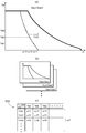
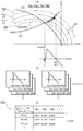
- the appropriate adjustment command threshold value ⁇ IdT can be obtained experimentally using the actual control device 2. For example, as shown in FIG. 8A, first, an arbitrary voltage is selected from the range of the DC voltage Vdc that the DC power supply 3 can take, and an arbitrary torque from the range of the target torque TM that the motor 4 can take. .
- Vdc1 is selected as the DC voltage Vdc
- the rotational speed ⁇ and the d-axis current adjustment command value ⁇ Id at the moment when the loss difference ⁇ Loss changes from positive to negative are obtained, and the rotational speed ⁇ and the DC voltage Vdc are obtained.
- the d-axis current adjustment command value ⁇ Id thus obtained is set as the adjustment command threshold value ⁇ IdT at the voltage speed ratio RV ⁇ and the target torque TM.
- the relationship among the voltage speed ratio RV ⁇ , the target torque TM, and the adjustment command threshold value ⁇ IdT is registered in the adjustment command threshold value map 35B as a map of the adjustment command threshold value ⁇ IdT.
- the field weakening / rectangular wave control mode A5 is executed from time t5 to time t8.
- Both the adjusted d-axis current command value Id and the adjusted q-axis current command value Iq set on the limit ellipse 63 increase.
- the adjusted d-axis current command value Id increases from Id8 to Id9
- the adjusted q-axis current command value Iq increases from Iq8 to Iq9.
- the d-axis current adjustment command value ⁇ Id also increases.
- the d-axis current adjustment command value ⁇ Id is gradually decreased. Also in this case, since the time until the d-axis current adjustment command value ⁇ Id becomes zero is ensured, when the strong field / rectangular wave control mode is shifted to the normal field / pulse width modulation control mode, the The field / pulse width modulation control mode can be executed.
- the AC motor 4 is a synchronous motor (IPMSM) having an embedded magnet structure that operates by three-phase AC
- IPMSM synchronous motor
- the embodiment of the present invention is not limited to this.
- a synchronous motor (SPMSM) having a surface magnet structure can be used as the AC motor 4, or other than the synchronous motor, for example, induction An electric motor or the like can also be used.
- an alternating current supplied to such an alternating current motor a single-phase other than three phases, a two-phase, or a polyphase alternating current having four or more phases can be used.
Landscapes
- Engineering & Computer Science (AREA)
- Power Engineering (AREA)
- Control Of Ac Motors In General (AREA)
Abstract
Description
まず、本実施形態に係る電動機駆動装置1の構成について図1に基づいて説明する。この電動機駆動装置1は、直流電圧Vdcを交流電圧に変換して電動機4に供給するインバータ6を備えている。また、電動機駆動装置1は、直流電圧Vdcを発生させる直流電源3と、直流電源3からの直流電圧Vdcを平滑化する平滑コンデンサC1と、を備えている。直流電源3としては、例えば、ニッケル水素二次電池やリチウムイオン二次電池等の各種二次電池、キャパシタ、或いはこれらの組合せ等が用いられる。直流電源3の電圧である直流電圧Vdcは、電圧センサ41により検出されて制御装置2へ出力される。
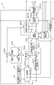
次に、図1に示される制御装置2の構成について、図2~図7を用いて詳細に説明する。以下に説明する制御装置2の各機能部は、マイクロコンピュータ等の論理回路を中核部材として、入力されたデータに対して種々の処理を行うためのハードウエア又はソフトウエア(プログラム)或いはその両方により構成されている。上記のとおり、制御装置2には、目標トルクTM及び磁極位置θが入力される。更に、制御装置2には、U相電流Iur、V相電流Ivr、及びW相電流Iwrも入力される。そこで、図2に示すように、制御装置2は、これらの目標トルクTM、磁極位置θ、磁極位置θから導出される電動機4の回転速度ω、及び各相電流Iur、Ivr、Iwrに基づいて、ベクトル制御法を用いた電流フィードバック制御を行い、電動機4に供給する電圧の指令値である電圧指令値Vd、Vqを決定する。そして、この電圧指令値Vd、Vqに基づいてインバータ6を駆動するためのスイッチング制御信号S1~S6を生成して出力し、当該インバータ6を介して電動機4の駆動制御を行う。
本実施形態では、制御装置2は、電圧指令値Vd、Vqに基づいてインバータ6を制御して行う電圧波形制御に関してPWM制御及び矩形波制御を実行可能に構成されている。また、基本電流指令値Idb、Iqbに対する界磁調整指令値としてのd軸電流調整指令値ΔIdを決定することにより電動機4の界磁磁束を調整する界磁制御に関して、通常界磁制御、強め界磁制御、及び弱め界磁制御を実行可能に構成されている。そして、制御装置2は、これらの電圧波形制御と界磁制御とを組み合わせて複数の制御モードの何れかを選択的に実行する。
次に、図2に示す制御装置2の機能ブロック図に基づいて、制御装置2の各機能部について説明する。図2に示すように、d軸電流指令値導出部21には、目標トルクTMが入力される。d軸電流指令値導出部21は、入力された目標トルクTMに基づいて基本d軸電流指令値Idbを導出する。ここで、基本d軸電流指令値Idbは、最大トルク制御を行う場合におけるd軸電流の指令値に相当する。本実施形態では、d軸電流指令値導出部21は、図4に示す基本d軸電流指令値マップを用いて、目標トルクTMの値に応じた基本d軸電流指令値Idbを導出する。図示の例では、目標トルクTMとして「TM1」の値が入力された場合には、これに応じて、d軸電流指令値導出部21は、基本d軸電流指令値Idbとして「Id1」を導出する。同様に、d軸電流指令値導出部21は、目標トルクTMとして「TM3」、「TM5」の値が入力された場合には、基本d軸電流指令値Idbとして「Id3」、「Id5」をそれぞれ導出する。このように導出された基本d軸電流指令値Idbは、加算器23へ入力される。加算器23には、後述する積分器32により導出されたd軸電流調整指令値ΔIdが更に入力される。加算器23は、下記の式(1)に示すように、基本d軸電流指令値Idbにd軸電流調整指令値ΔIdを加算し、調整後d軸電流指令値Idを導出する。
Id=Idb+ΔId・・・(1)
Vd=Vzd-Eq
=Vzd-ω・Lq・Iqr・・・(2)
この式(2)に示されるように、q軸電機子反作用Eqは、電動機4の回転速度ω、実q軸電流Iqr、及びq軸インダクタンスLqに基づいて導出される。
Vq=Vzq+Ed+Em
=Vzq+ω・Ld・Idr+ω・MIf・・・(3)
この式(3)に示されるように、d軸電機子反作用Edは、電動機4の回転速度ω、実d軸電流Idr、及びd軸インダクタンスLdに基づいて導出される。また、誘起電圧Emは、永久磁石の電機子鎖交磁束の実効値により定まる誘起電圧定数MIf及び電動機4の回転速度ωに基づいて導出される。
M=√(Vd2+Vq2)/Vdc・・・(4)
本実施形態では、変調率Mは、直流電圧Vdcに対するインバータ6の出力電圧波形の基本波成分の実効値の比率であり、ここでは、3相の線間電圧実効値を直流電圧Vdcの値で除算した値として導出される。本実施形態においては、この変調率Mが、そのときの直流電圧Vdcに対する電圧指令値Vd、Vqの大きさを表す電圧指標に相当する。上記のとおり、変調率Mの最大値(最大変調率Mmax)は、矩形波制御を実行している際の変調率Mに相当する「0.78」である。ここでは、この最大変調率Mmaxは、矩形波しきい値Mbでもある。
ΔM=M-MT・・・(5)
本実施形態では、変調率偏差ΔMは、電圧指令値Vd、Vqがそのときの直流電圧Vdcによって出力し得る最大の交流電圧の値を超えている程度を表す。従って、変調率偏差ΔMは、実質的には直流電圧Vdcの不足の程度を表す電圧不足指標として機能する。
図3に示すように、モード制御部5は、強め界磁制御領域Fを除いて、電動機4の回転速度ω及び目標トルクTMが高くなるに従って、通常界磁・通常PWM制御モードA1a、通常界磁・過変調PWM制御モードA1b、弱め界磁・過変調PWM制御モードA4a、弱め界磁・矩形波制御モードA5の順に制御モードを移行させる。上記のとおり、これらの各制御モード間の境界(曲線L1、L2、L3)は、通常界磁制御(最大トルク制御)中における変調率Mが一定となる位置に設定されている。この中で、曲線L1は、通常界磁制御中における変調率Mが最大変調率Mmax(=0.78)となる位置に設定されており、回転速度ω及び目標トルクTMに基づいて通常界磁制御を行うべく導出した変調率Mが最大変調率Mmaxを超える状態では、制御装置2は、弱め界磁・矩形波制御モードA5を実行する。
Ms=MT+ΔMs・・・(6)
本実施形態では、指令変調率MTが「0.78」に設定され、強め界磁開始偏差ΔMsが「-0.073」に設定されているので、強め界磁しきい値Msは過変調しきい値Moと等しい「0.707」となる。このため、目標トルクTMが強め界磁許容トルク範囲TMR内にある状態で通常界磁・通常PWM制御モードA1aの実行中に変調率Mが強め界磁しきい値Msを超えた場合、すなわち電動機4の動作点が強め界磁制御領域Fに入った場合、界磁調整部8は強め界磁制御を開始する。
上記のとおり、本実施形態に係る制御装置2では、矩形波制御の実行中は、変調率Mを矩形波しきい値Mbである最大変調率Mmaxに維持するようにd軸電流調整指令値ΔIdが決定され、強め界磁制御や弱め界磁制御が実行される。そのため、変調率Mのみによって矩形波制御とPWM制御とを切り替える構成では、電動機4の運転状態が変化しても矩形波制御は終了しない。すなわち、回転速度ω及び目標トルクTMの一方又は双方が低下して電動機4の動作点が、図3の曲線L2より左側の通常界磁・通常PWM制御モードA1aの領域に入った場合であっても、界磁磁束を強める方向にd軸電流調整指令値ΔIdが大きくなるだけで矩形波制御及び強め界磁制御は終了しない。このため、d軸電流調整指令値ΔIdが大きくなることにより効率が低下し、或いは回転速度ωが低い領域で矩形波制御を行うことにより電動機4の出力トルクに振動等が生じる可能性がある。そこで、モード制御部5は、このような場合に適切に強め界磁制御を終了させることにより、矩形波制御を終了させることができるように強め界磁終了制御を行う。
(A)電動機4の回転速度ω<回転速度しきい値ωT
(B)d軸電流調整指令値ΔId≧調整指令しきい値ΔIdT
(C)目標トルクTMが強め界磁許容トルク範囲TMR外であること
なお、本実施形態においては、上記の条件(C)に示すように、目標トルクTMが強め界磁許容トルク範囲TMR外であることも強め界磁終了条件に含めて判定することにより、強め界磁許容トルク範囲TMR内でのみ強め界磁制御を行なうように規制している。以下では、これらの強め界磁終了条件及び強め界磁制御の終了動作について詳細に説明する。
上記のように、モード制御部5は、強め界磁終了条件(A)として、電動機4の回転速度ωに基づく終了条件を用いる。すなわち、モード制御部5は、電動機4の回転速度ωが、目標トルクTM及び直流電圧Vdcに基づいて定まる回転速度しきい値ωT未満となったこと(ω<ωT)を条件として、界磁調整部8による強め界磁制御を終了させる。本実施形態では、目標トルクTM及び直流電圧Vdcの双方の値に応じて、通常界磁制御の実行中において変調率Mが上述した強め界磁しきい値Ms(=0.707)となる電動機4の回転速度ωを、回転速度しきい値ωTとする。
上記のように、モード制御部5は、強め界磁終了条件(B)として、界磁調整指令値としてのd軸電流調整指令値ΔIdに基づく終了条件を用いる。すなわち、モード制御部5は、d軸電流調整指令値ΔIdが、界磁磁束を強める方向に、目標トルクTM及び電圧速度比RVωに基づいて定まる調整指令しきい値ΔIdT以上となったこと(ΔId≧ΔIdT)を条件として、界磁調整部8による強め界磁制御を終了させる。ここで、電圧速度比RVωは、直流電圧Vdcと電動機4の回転速度ωとの比である。本実施形態では、強め界磁制御と共に矩形波制御を実行することにより得られるインバータ6におけるスイッチング損失の低減効果と、界磁磁束を強める方向にd軸電流調整指令値ΔIdを増大することによる効率の悪化との関係に着目する。具体的には、通常界磁・PWM制御モードA1(ここでは通常界磁・通常PWM制御モードA1a)を実行した場合の電動機4及び電動機駆動装置1の損失を通常時損失Loss1とし、強め界磁・矩形波制御モードA3を実行した場合の電動機4及び電動機駆動装置1の損失を強め界磁時損失Loss2とし、強め界磁制御を実行することによる効率向上分を損失差分ΔLoss(=Loss1-Loss2)とする。そして、強め界磁時損失Loss2が通常時損失Loss1より少なくなる、すなわち、損失差分ΔLossが正(ΔLoss>0)となるd軸電流調整指令値ΔIdの範囲における界磁磁束を強める方向の上限を、調整指令しきい値ΔIdTとする。
また、本実施形態では、モード制御部5は、強め界磁終了条件(C)として、強め界磁許容トルク範囲TMRに基づく終了条件を用いる。すなわち、モード制御部5は、電動機4の目標トルクTMが所定の強め界磁許容トルク範囲TMRから外れている場合には、界磁調整部8が強め界磁制御を実行しないように、強め界磁制御を終了させる。すなわち、モード制御部5は、強め界磁許容トルク範囲TMRの上限を許容トルク上限TMRHとし、下限を許容トルク下限TMRLとして、目標トルクTM<許容トルク下限TMRL、又は目標トルクTM>許容トルク上限TMRHのときに強め界磁制御を終了させる。ここで、許容トルク上限TMRHは、例えば、電動機4に流れる交流電流の基本波成分以外の高調波成分が大きくなり易い矩形波制御を行った際に、電動機4の電機子コイルに流れる電流が当該電動機4に許容される電流制限値を超えないように設定すると好適である。また、許容トルク下限TMRLは、例えば、出力トルクが小さすぎるために矩形波制御を行うのに適さないトルク範囲を強め界磁許容トルク範囲TMRから除外するように設定すると好適である。
そして、モード制御部5は、上述した強め界磁終了条件(A)~(C)のいずれかを満たす場合には、d軸電流調整指令値ΔIdをゼロとする制御を行う。すなわち、モード制御部5は、強め界磁終了条件を満たす場合には、d軸電流調整指令値ΔIdをゼロとする指令を積分器32へ出力し、積分器32が出力するd軸電流調整指令値ΔIdをゼロとする。この際、モード制御部5は、d軸電流調整指令値ΔIdを現在値からゼロに向って一定の変化速度で変化させるように界磁調整部8を制御する。すなわち、強め界磁制御の実行中は、d軸電流調整指令値ΔIdは正の値となっているので、モード制御部5は、強め界磁制御を終了させる際には、d軸電流調整指令値ΔIdを時間の経過に従って現在値からゼロまで次第に低下(減少)させる。モード制御部5は、このように強め界磁制御を終了する際に、界磁磁束の調整量を減少させる方向にd軸電流調整指令値ΔIdを次第に変化させることで変調率Mを次第に低下させる制御を行う。これにより、変調率Mを、矩形波制御モードが実行される矩形波しきい値Mb(最大変調率Mmax=0.78)から次第に低下させ、d軸電流調整指令値ΔIdがゼロとなるまでの間であって且つ変調率Mが過変調しきい値Mo(=0.707)となるまでの間に強め界磁・過変調PWM制御モードA2b(強め界磁・PWM制御モードA2)を実行する。そして、d軸電流調整指令値ΔIdがゼロとなり、変調率Mが過変調しきい値Mo未満となったときに、通常界磁・通常PWM制御モードA1a(通常界磁・PWM制御モードA1)に移行する。
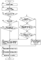
次に、制御装置2の各部の動作について、図9及び図10を用いて詳細に説明する。図9は、本実施形態に係る制御装置2における電圧指令値Vd、Vqの導出までの各部の動作の流れを示すフローチャートである。
(1)上記の実施形態では、強め界磁終了条件(A)で用いる回転速度しきい値ωTとして、目標トルクTM及び直流電圧Vdcに基づいて定まる値を用いる場合を例として説明した。しかし、本発明の実施形態はこれに限定されない。例えば、回転速度しきい値ωTを、目標トルクTM及び直流電圧Vdcに関わらず一定の値に設定することも、本発明の好適な実施形態の一つである。また、回転速度しきい値ωTを、目標トルクTM及び直流電圧Vdcのいずれか一方に基づいて定まる値とすることも、本発明の好適な実施形態の一つである。更に、回転速度しきい値ωTを、目標トルクTM、直流電圧Vdc、調整指令しきい値ΔIdT等に基づいて所定の式により算出した値としても好適である。このように回転速度しきい値ωTを定める場合、当該回転速度しきい値ωTに基づく強め界磁終了条件(A)と、上述した調整指令しきい値ΔIdTに基づく強め界磁終了条件(B)との双方が満たされた場合に強め界磁制御を終了させる構成とすると特に好適である。この場合、モード制御部5は、d軸電流調整指令値ΔIdが、界磁磁束を強める方向に調整指令しきい値ΔIdT以上となり、且つ回転速度ωが回転速度しきい値ωT未満となったことを条件として、強め界磁制御を終了させる。なお、この場合においても、強め界磁許容トルク範囲TMRに基づく強め界磁終了条件(C)は選択的条件とし、条件(A)且つ条件(B)と条件(C)とのいずれかが満たされた場合に強め界磁制御を終了させる構成とすると更に好適である。
2:制御装置
4:交流電動機
5:モード制御部
6:インバータ(直流交流変換部)
7:電流指令決定部
8:界磁調整部
9:電圧指令決定部
10:電圧波形制御部
Vdc:直流電圧
TM:目標トルク
ω:回転速度
Idb:基本d軸電流指令値(基本電流指令値)
Id:調整後d軸電流指令値(調整後電流指令値)
Iqb:基本q軸電流指令値(基本電流指令値)
Iq:調整後q軸電流指令値(調整後電流指令値)
ΔId:d軸電流調整指令値(界磁調整指令値)
Vd:d軸電圧指令値(電圧指令値)
Vq:q軸電圧指令値(電圧指令値)
M:変調率(電圧指標)
Mb:矩形波しきい値
Ms:強め界磁しきい値
RVω:電圧速度比
ωT:回転速度しきい値
ΔIdT:調整指令しきい値
TMR:強め界磁許容トルク範囲
A1:通常界磁・PWM制御モード
A2:強め界磁・PWM制御モード
A3:強め界磁・矩形波制御モード
Claims (9)
- 直流電圧を交流電圧に変換して交流電動機に供給する直流交流変換部を備えた電動機駆動装置の制御を行う制御装置であって、
前記交流電動機の目標トルクに基づいて、前記直流交流変換部から前記交流電動機に供給する電流の指令値である基本電流指令値を決定する電流指令決定部と、
前記基本電流指令値の調整値である界磁調整指令値を決定する界磁調整部と、
前記界磁調整指令値により前記基本電流指令値を調整した後の調整後電流指令値、及び前記交流電動機の回転速度に基づいて、前記直流交流変換部から前記交流電動機に供給する電圧の指令値である電圧指令値を決定する電圧指令決定部と、
前記電圧指令値に基づいて前記直流交流変換部を制御し、パルス幅変調制御及び矩形波制御を少なくとも含む電圧波形制御を実行する電圧波形制御部と、
前記界磁調整部及び前記電圧波形制御部を制御するモード制御部と、を備え、
前記電圧波形制御部は、前記直流電圧に対する前記電圧指令値の大きさを表す電圧指標が所定の矩形波しきい値未満である場合には前記パルス幅変調制御を実行し、前記電圧指標が前記矩形波しきい値以上である場合には前記矩形波制御を実行し、
前記界磁調整部は、前記基本電流指令値に対して前記交流電動機の界磁磁束を強める調整を行うように前記界磁調整指令値を決定する強め界磁制御、及び前記基本電流指令値に対する調整を行わないように前記界磁調整指令値を決定する通常界磁制御を少なくとも含む界磁制御を実行するように構成され、前記電圧指標が前記矩形波しきい値より小さい所定の強め界磁しきい値以上となったことを条件として前記強め界磁制御を実行し、
前記モード制御部は、前記直流電圧と前記交流電動機の回転速度との比を電圧速度比として、前記界磁調整指令値が、前記界磁磁束を強める方向に、前記目標トルク及び前記電圧速度比に基づいて定まる調整指令しきい値以上となったことを条件として、前記界磁調整部による前記強め界磁制御を終了させる電動機駆動装置の制御装置。 - 前記モード制御部は、前記強め界磁制御と共に前記矩形波制御を実行する強め界磁・矩形波制御モード中に、前記強め界磁制御を終了する際には、前記界磁磁束の調整量を減少させる方向に前記界磁調整指令値を次第に変化させることで前記電圧指標を次第に低下させ、前記強め界磁制御と共に前記パルス幅変調制御を実行する強め界磁・パルス幅変調制御モードを経て、前記通常界磁制御と共に前記パルス幅変調制御を実行する通常界磁・パルス幅変調制御モードに移行させる請求項1に記載の電動機駆動装置の制御装置。
- 前記通常界磁制御と共に前記パルス幅変調制御を実行する通常界磁・パルス幅変調制御モードを実行した場合の前記交流電動機及び前記電動機駆動装置の損失を通常時損失とし、前記強め界磁制御と共に前記矩形波制御を実行する強め界磁・矩形波制御モードを実行した場合の前記交流電動機及び前記電動機駆動装置の損失を強め界磁時損失として、
前記強め界磁時損失が前記通常時損失より少なくなる前記界磁調整指令値の範囲における前記界磁磁束を強める方向の上限を、前記調整指令しきい値とする請求項1又は2に記載の電動機駆動装置の制御装置。 - 前記モード制御部は、前記界磁調整指令値が前記調整指令しきい値以上となったこと、及び前記回転速度が所定の回転速度しきい値未満となったこと、の双方の条件を判断し、少なくとも一方の条件が満たされた場合に、前記強め界磁制御を終了させる請求項1から3のいずれか一項に記載の電動機駆動装置の制御装置。
- 前記回転速度しきい値は、前記目標トルク及び前記直流電圧に基づいて定まる請求項4に記載の電動機駆動装置の制御装置。
- 前記目標トルク及び前記直流電圧の双方の値に応じて、前記通常界磁制御の実行中において前記電圧指標が前記強め界磁しきい値となる回転速度を、前記回転速度しきい値とする請求項5に記載の電動機駆動装置の制御装置。
- 前記モード制御部は、前記交流電動機の目標トルクが所定の強め界磁許容トルク範囲から外れている場合には、前記界磁調整部が前記強め界磁制御を実行しないように制御する請求項1から6のいずれか一項に記載の電動機駆動装置の制御装置。
- 前記モード制御部は、前記強め界磁制御を終了させる際には、前記界磁調整指令値を現在値からゼロに向って一定の変化速度で変化させるように前記界磁調整部を制御する請求項1から7のいずれか一項に記載の電動機駆動装置の制御装置。
- 前記電圧指令決定部は、直流交流変換部から前記交流電動機に供給される電流の実際の値である実電流値に基づいて、前記調整後電流指令値に対するフィードバック制御を行い、前記電圧指令値を決定する請求項1から8のいずれか一項に記載の電動機駆動装置の制御装置。
Priority Applications (2)
| Application Number | Priority Date | Filing Date | Title |
|---|---|---|---|
| CN2011800098165A CN102763321A (zh) | 2010-03-31 | 2011-02-04 | 电动机驱动装置的控制装置 |
| DE112011100226T DE112011100226T5 (de) | 2010-03-31 | 2011-02-04 | Steuerungsvorrichtung einer Motorantriebsvorrichtung |
Applications Claiming Priority (2)
| Application Number | Priority Date | Filing Date | Title |
|---|---|---|---|
| JP2010-081515 | 2010-03-31 | ||
| JP2010081515A JP5120670B2 (ja) | 2010-03-31 | 2010-03-31 | 電動機駆動装置の制御装置 |
Publications (1)
| Publication Number | Publication Date |
|---|---|
| WO2011122105A1 true WO2011122105A1 (ja) | 2011-10-06 |
Family
ID=44708830
Family Applications (1)
| Application Number | Title | Priority Date | Filing Date |
|---|---|---|---|
| PCT/JP2011/052400 Ceased WO2011122105A1 (ja) | 2010-03-31 | 2011-02-04 | 電動機駆動装置の制御装置 |
Country Status (5)
| Country | Link |
|---|---|
| US (1) | US20110241583A1 (ja) |
| JP (1) | JP5120670B2 (ja) |
| CN (1) | CN102763321A (ja) |
| DE (1) | DE112011100226T5 (ja) |
| WO (1) | WO2011122105A1 (ja) |
Families Citing this family (33)
| Publication number | Priority date | Publication date | Assignee | Title |
|---|---|---|---|---|
| MX2013000965A (es) * | 2010-07-23 | 2013-04-24 | Mitsubishi Electric Corp | Aparato de control y metodo de control para maquina giratoria de ca. |
| US8816622B2 (en) * | 2010-07-27 | 2014-08-26 | Mitsubishi Electric Corporation | Control apparatus for rotating machine |
| JP5718668B2 (ja) * | 2011-02-15 | 2015-05-13 | トヨタ自動車株式会社 | 回転電機駆動システム |
| DE102011085853A1 (de) * | 2011-11-07 | 2013-05-08 | Siemens Aktiengesellschaft | Verfahren und Anordnung zum Betrieb von Synchronmotoren |
| JP2014054066A (ja) * | 2012-09-06 | 2014-03-20 | Toyota Motor Corp | 回転電機駆動システムの制御装置 |
| JP5955761B2 (ja) * | 2012-12-25 | 2016-07-20 | トヨタ自動車株式会社 | 車両の制御装置 |
| JP5986013B2 (ja) * | 2013-02-19 | 2016-09-06 | 株式会社日立製作所 | 電動機駆動システム |
| JP6183165B2 (ja) * | 2013-11-12 | 2017-08-23 | サンケン電気株式会社 | 誘導電動機制御装置及び誘導電動機制御方法 |
| JP2015136237A (ja) * | 2014-01-17 | 2015-07-27 | 株式会社安川電機 | 回転電機制御装置、回転電機制御方法、及び制御マップの作成方法 |
| DE102014104488A1 (de) * | 2014-03-31 | 2015-10-01 | Robert Bosch Automotive Steering Gmbh | Verfahren zur Ansteuerung eines Elektromotors für ein Hilfskraft-Lenksystem |
| CN104079230B (zh) * | 2014-07-07 | 2016-09-28 | 神王伟国 | 异步电动机效率优化控制的方法、装置、系统及电动汽车 |
| FR3024616B1 (fr) * | 2014-07-31 | 2016-07-15 | Renault Sa | Procede et dispositif de commande du couple electromagnetique d'un groupe motopropulseur |
| US9634579B2 (en) * | 2015-04-03 | 2017-04-25 | Hamilton Sundstrand Corporation | Systems and methods for controlling inverters |
| WO2017143434A1 (en) * | 2016-02-23 | 2017-08-31 | Canadian Space Agency | Energy-efficient motor drive with or without open-circuited phase |
| JP6289545B2 (ja) * | 2016-06-15 | 2018-03-07 | 三菱電機株式会社 | 回転電機の制御方法 |
| DE102016118170A1 (de) * | 2016-09-26 | 2018-03-29 | Wittenstein Se | Verfahren und vorrichtung zum abbauen elastisch gespeicherter energie |
| CN106849805A (zh) * | 2017-02-09 | 2017-06-13 | 澳特卡新能源科技(上海)有限公司 | 一种电动压缩机驱动电机的弱磁控制方法 |
| US9774279B1 (en) * | 2017-03-02 | 2017-09-26 | Borgwarner Inc. | Brushless DC motor control and method |
| DE102017217913A1 (de) * | 2017-10-09 | 2019-04-11 | Robert Bosch Gmbh | Verfahren zum Wechseln zwischen Blockansteuerung und PWM-Ansteuerung einer elektrischen Maschine |
| CN110504891B (zh) * | 2018-05-16 | 2021-09-03 | 台达电子工业股份有限公司 | 马达驱动电路及其控制方法 |
| JP7144197B2 (ja) * | 2018-06-01 | 2022-09-29 | 株式会社Soken | 回転電機の制御装置 |
| CN112423938B (zh) | 2018-07-18 | 2023-07-04 | 松下知识产权经营株式会社 | 电动工具、控制方法和程序 |
| JP7052713B2 (ja) * | 2018-12-27 | 2022-04-12 | 株式会社豊田自動織機 | インバータ制御装置 |
| CN111404429B (zh) * | 2018-12-28 | 2021-11-12 | 比亚迪股份有限公司 | 一种车辆及其电机控制方法与装置、计算机可读存储介质 |
| CN110829920A (zh) * | 2019-11-04 | 2020-02-21 | 中国第一汽车股份有限公司 | 一种调制装置及系统 |
| US11456680B2 (en) * | 2020-05-08 | 2022-09-27 | Hamilton Sundstrand Corporation | Over-modulation pulse width modulation with maximum output and minimum harmonics |
| JP6949286B1 (ja) * | 2021-03-19 | 2021-10-13 | 三菱電機株式会社 | 制御装置、および電力変換装置 |
| IT202100018689A1 (it) * | 2021-07-15 | 2023-01-15 | Ferrari Spa | Procedimento ed apparato per controllare un motore elettrico |
| CN115871481B (zh) * | 2021-09-29 | 2025-05-02 | 本田技研工业株式会社 | 电动发电机控制系统及混合动力车辆 |
| US11787384B2 (en) * | 2021-11-22 | 2023-10-17 | GM Global Technology Operations LLC | Electric drive system and method |
| KR102712341B1 (ko) * | 2021-12-13 | 2024-09-30 | 현대모비스 주식회사 | 모터의 약자속 제어를 위한 데이터 맵 작성 방법 및 시스템 |
| WO2025187058A1 (ja) * | 2024-03-08 | 2025-09-12 | Astemo株式会社 | モータ制御装置及び電気車 |
| US20260005631A1 (en) * | 2024-06-27 | 2026-01-01 | Renesas Electronics Corporation | Inverter control device and an inverter control method |
Citations (4)
| Publication number | Priority date | Publication date | Assignee | Title |
|---|---|---|---|---|
| JP2006081287A (ja) * | 2004-09-09 | 2006-03-23 | Aisin Aw Co Ltd | 電動駆動制御装置、電動駆動制御方法及びそのプログラム |
| JP2006311770A (ja) * | 2005-05-02 | 2006-11-09 | Toyota Motor Corp | モータ駆動システムの制御装置 |
| JP2007259538A (ja) * | 2006-03-22 | 2007-10-04 | Aisin Aw Co Ltd | 電動駆動制御装置及び電動駆動制御方法 |
| JP2008079399A (ja) * | 2006-09-20 | 2008-04-03 | Toshiba Corp | 車両制御装置 |
Family Cites Families (1)
| Publication number | Priority date | Publication date | Assignee | Title |
|---|---|---|---|---|
| JP4280573B2 (ja) * | 2003-07-31 | 2009-06-17 | トヨタ自動車株式会社 | 負荷駆動装置 |
-
2010
- 2010-03-31 JP JP2010081515A patent/JP5120670B2/ja not_active Expired - Fee Related
-
2011
- 2011-02-01 US US13/018,953 patent/US20110241583A1/en not_active Abandoned
- 2011-02-04 CN CN2011800098165A patent/CN102763321A/zh active Pending
- 2011-02-04 WO PCT/JP2011/052400 patent/WO2011122105A1/ja not_active Ceased
- 2011-02-04 DE DE112011100226T patent/DE112011100226T5/de not_active Ceased
Patent Citations (4)
| Publication number | Priority date | Publication date | Assignee | Title |
|---|---|---|---|---|
| JP2006081287A (ja) * | 2004-09-09 | 2006-03-23 | Aisin Aw Co Ltd | 電動駆動制御装置、電動駆動制御方法及びそのプログラム |
| JP2006311770A (ja) * | 2005-05-02 | 2006-11-09 | Toyota Motor Corp | モータ駆動システムの制御装置 |
| JP2007259538A (ja) * | 2006-03-22 | 2007-10-04 | Aisin Aw Co Ltd | 電動駆動制御装置及び電動駆動制御方法 |
| JP2008079399A (ja) * | 2006-09-20 | 2008-04-03 | Toshiba Corp | 車両制御装置 |
Also Published As
| Publication number | Publication date |
|---|---|
| JP5120670B2 (ja) | 2013-01-16 |
| CN102763321A (zh) | 2012-10-31 |
| US20110241583A1 (en) | 2011-10-06 |
| JP2011217469A (ja) | 2011-10-27 |
| DE112011100226T5 (de) | 2012-10-31 |
Similar Documents
| Publication | Publication Date | Title |
|---|---|---|
| JP5120670B2 (ja) | 電動機駆動装置の制御装置 | |
| JP5120669B2 (ja) | 電動機駆動装置の制御装置 | |
| JP5246508B2 (ja) | 電動機駆動装置の制御装置 | |
| JP5370769B2 (ja) | 電動機駆動装置の制御装置 | |
| JP5035641B2 (ja) | 電動機駆動装置の制御装置 | |
| JP5257365B2 (ja) | モータ制御装置とその制御方法 | |
| US7595600B2 (en) | Method and system for torque control in permanent magnet machines | |
| CN103782507B (zh) | 电动机控制系统 | |
| JP5803559B2 (ja) | 回転電機制御装置 | |
| CN103781654B (zh) | 电动机控制系统 | |
| JP5435292B2 (ja) | 制御装置 | |
| WO2012132703A1 (ja) | 電動機制御装置 | |
| CN102197581A (zh) | 交流电动机的控制装置以及控制方法 | |
| JP5534323B2 (ja) | 電動機制御装置 | |
| JP4008724B2 (ja) | モータ制御装置 | |
| JP2015109770A (ja) | 電動機駆動装置 | |
| WO2018139298A1 (ja) | 交流電動機の制御装置 | |
| JP2014128051A (ja) | 車両の制御装置 | |
| JP5370748B2 (ja) | 電動機駆動装置の制御装置 | |
| WO2018116668A1 (ja) | モータ制御装置および電動車両 | |
| RU2463699C1 (ru) | Устройство преобразования мощности для возбуждения электродвигателя |
Legal Events
| Date | Code | Title | Description |
|---|---|---|---|
| WWE | Wipo information: entry into national phase |
Ref document number: 201180009816.5 Country of ref document: CN |
|
| 121 | Ep: the epo has been informed by wipo that ep was designated in this application |
Ref document number: 11762346 Country of ref document: EP Kind code of ref document: A1 |
|
| WWE | Wipo information: entry into national phase |
Ref document number: 112011100226 Country of ref document: DE Ref document number: 1120111002262 Country of ref document: DE |
|
| 122 | Ep: pct application non-entry in european phase |
Ref document number: 11762346 Country of ref document: EP Kind code of ref document: A1 |