WO2011122092A1 - タービン - Google Patents
タービン Download PDFInfo
- Publication number
- WO2011122092A1 WO2011122092A1 PCT/JP2011/051895 JP2011051895W WO2011122092A1 WO 2011122092 A1 WO2011122092 A1 WO 2011122092A1 JP 2011051895 W JP2011051895 W JP 2011051895W WO 2011122092 A1 WO2011122092 A1 WO 2011122092A1
- Authority
- WO
- WIPO (PCT)
- Prior art keywords
- fin
- rotation axis
- upstream side
- axis direction
- seal
- Prior art date
Links
Images


Classifications
-
- F—MECHANICAL ENGINEERING; LIGHTING; HEATING; WEAPONS; BLASTING
- F01—MACHINES OR ENGINES IN GENERAL; ENGINE PLANTS IN GENERAL; STEAM ENGINES
- F01D—NON-POSITIVE DISPLACEMENT MACHINES OR ENGINES, e.g. STEAM TURBINES
- F01D5/00—Blades; Blade-carrying members; Heating, heat-insulating, cooling or antivibration means on the blades or the members
- F01D5/12—Blades
- F01D5/22—Blade-to-blade connections, e.g. for damping vibrations
- F01D5/225—Blade-to-blade connections, e.g. for damping vibrations by shrouding
-
- F—MECHANICAL ENGINEERING; LIGHTING; HEATING; WEAPONS; BLASTING
- F01—MACHINES OR ENGINES IN GENERAL; ENGINE PLANTS IN GENERAL; STEAM ENGINES
- F01D—NON-POSITIVE DISPLACEMENT MACHINES OR ENGINES, e.g. STEAM TURBINES
- F01D11/00—Preventing or minimising internal leakage of working-fluid, e.g. between stages
- F01D11/02—Preventing or minimising internal leakage of working-fluid, e.g. between stages by non-contact sealings, e.g. of labyrinth type
-
- F—MECHANICAL ENGINEERING; LIGHTING; HEATING; WEAPONS; BLASTING
- F01—MACHINES OR ENGINES IN GENERAL; ENGINE PLANTS IN GENERAL; STEAM ENGINES
- F01D—NON-POSITIVE DISPLACEMENT MACHINES OR ENGINES, e.g. STEAM TURBINES
- F01D11/00—Preventing or minimising internal leakage of working-fluid, e.g. between stages
- F01D11/08—Preventing or minimising internal leakage of working-fluid, e.g. between stages for sealing space between rotor blade tips and stator
-
- F—MECHANICAL ENGINEERING; LIGHTING; HEATING; WEAPONS; BLASTING
- F01—MACHINES OR ENGINES IN GENERAL; ENGINE PLANTS IN GENERAL; STEAM ENGINES
- F01D—NON-POSITIVE DISPLACEMENT MACHINES OR ENGINES, e.g. STEAM TURBINES
- F01D25/00—Component parts, details, or accessories, not provided for in, or of interest apart from, other groups
-
- F—MECHANICAL ENGINEERING; LIGHTING; HEATING; WEAPONS; BLASTING
- F16—ENGINEERING ELEMENTS AND UNITS; GENERAL MEASURES FOR PRODUCING AND MAINTAINING EFFECTIVE FUNCTIONING OF MACHINES OR INSTALLATIONS; THERMAL INSULATION IN GENERAL
- F16J—PISTONS; CYLINDERS; SEALINGS
- F16J15/00—Sealings
- F16J15/44—Free-space packings
- F16J15/447—Labyrinth packings
- F16J15/4472—Labyrinth packings with axial path
-
- F—MECHANICAL ENGINEERING; LIGHTING; HEATING; WEAPONS; BLASTING
- F05—INDEXING SCHEMES RELATING TO ENGINES OR PUMPS IN VARIOUS SUBCLASSES OF CLASSES F01-F04
- F05D—INDEXING SCHEME FOR ASPECTS RELATING TO NON-POSITIVE-DISPLACEMENT MACHINES OR ENGINES, GAS-TURBINES OR JET-PROPULSION PLANTS
- F05D2240/00—Components
- F05D2240/55—Seals
Definitions
- the present invention relates to a turbine used in a power plant, a chemical plant, a gas plant, a steel mill, a ship and the like.
- a steam turbine including a plurality of blades provided radially on a shaft body is used on the downstream side.
- the pressure energy of the steam is converted into velocity energy by the stationary blade, and this velocity energy is converted into rotational energy (mechanical energy) by the blade.
- a reaction turbine among the steam turbines pressure energy is converted into velocity energy even in the moving blades, and velocity energy is converted into rotational energy (mechanical energy) by reaction force from which steam is ejected.
- a radial gap is formed between the tip of the moving blade and a casing that forms a steam flow path by surrounding the moving blade, and between the tip of the stationary blade and the shaft body.
- a gap in the radial direction is also formed.
- the leaked steam that passes through the gap at the tip of the moving blade downstream does not impart a rotational force to the moving blade.
- the leaked steam passing through the gap at the tip of the stationary blade to the downstream side does not convert the pressure energy into velocity energy by the stationary blade, and therefore hardly gives the rotational force to the downstream moving blade. Therefore, in order to improve the performance of the steam turbine, it is important to reduce the amount of leaked steam that passes through the gap.
- a step portion whose height gradually increases from the upstream side toward the downstream side in the axial direction is provided at the tip of the moving blade, and a gap is formed between the step portion and the casing.
- a seal structure provided with seal fins is disclosed. According to such a seal structure, the leakage flow that has passed through the gap between the step portion and the seal fin collides with the step surface forming the edge of the step portion, and the flow resistance increases, thereby reducing the leakage flow rate. Is done.
- the present invention has been made in consideration of such circumstances, and an object thereof is to provide a high-performance turbine capable of further reducing the leakage flow rate.
- the turbine according to the present invention is a turbine provided with a blade and a structure that is provided with a clearance from the tip side of the blade and that rotates relative to the blade around a rotation axis. Further, one of the tip of the blade and the portion corresponding to the tip of the structure has a stepped surface and is on the other side of the tip and the portion of the structure. A projecting step portion is provided, and a seal fin extending toward the step portion is provided on the other of the tip portion and the portion of the structure, and the blade tip portion and the structure body A cavity is formed between the seal fin and the partition facing the seal fin on the upstream side in the rotational axis direction of the structure.
- the seal fin limits a space between the fin main body part that forms a minute gap between the step part and the upstream side of the minute gap in the rotation axis direction, and the gap between the cavity and the minute gap. And a space restricting portion that forms a small cavity.
- the fluid that has flowed into the cavity collides with the step surface forming the edge of the step portion, that is, the surface facing the upstream side in the rotation axis direction of the step portion, the direction of the flow changes, and the upstream side
- the main vortex swirling in a certain direction (first direction) is generated in the cavity.
- a separation vortex that rotates in a direction opposite to the rotation direction of the main vortex (second direction) is generated.
- this separation vortex is generated, a contraction effect is generated that reduces the leakage flow that passes through the minute gap between the fin body portion and the step portion.
- the space limiting portion forms a small cavity between the cavity and the minute gap, the flow of the separation vortex is strengthened in the small cavity whose space is narrower than that of the cavity. Therefore, the contraction effect by the separation vortex is sufficiently enhanced, and the leakage flow rate passing through the minute gap can be further reduced.
- the space limiting portion has a rotation axis direction wall surface extending from the fin main body portion to the upstream side in the rotation axis direction.
- the flow of the separation vortex is restricted by the wall surface in the rotation axis direction and the fin main body. Therefore, the flow of the separation vortex is further strengthened, and the contraction effect can be further enhanced.
- the wall surface in the direction of the rotation axis is recessed in an arc shape in a cross section at a plane including the rotation axis.
- the peeling vortex flows in an arc shape along the wall surface in the rotation axis direction in the cross section on the plane including the rotation axis. Therefore, the flow direction of the separation vortex can be changed smoothly, and the restriction effect on the separation vortex can be strengthened. Therefore, the flow of the separation vortex is further strengthened, and the contraction effect can be further enhanced.
- the wall surface in the rotation axis direction is connected to the fin main body portion in an arc shape in a cross section at a plane including the rotation shaft.
- the peeling vortex flows in an arc shape along the fin main body portion from the wall surface in the rotation axis direction in the cross section on the plane including the rotation axis. Therefore, the separation vortex that flows along the wall surface in the rotation axis direction can smoothly flow along the fin body portion, and the effect of regulating the separation vortex can be strengthened. Therefore, the flow of the separation vortex is further strengthened, and the contraction effect can be further enhanced.
- the fin main body portion extends obliquely toward the upstream side in the rotational axis direction.
- the downflow of the separation vortex flows toward the leakage flow that flows downstream in the rotational axis direction. Therefore, in the vicinity of the tip of the fin main body, the rotational axis direction velocity component V X of the flow velocity in the flow in which the leakage flow and the downflow of the separation vortex merge is reduced.
- the radial velocity component of the flow velocity in the flow described above joins the V R, since contraction effective as separation vortex V X / V R approaches 0 increases, the contraction effect It can be further increased.
- the space limiting portion is provided with an interval on the upstream side in the rotation axis direction of the fin main body portion, and extends toward the step portion.
- the wall is a radial wall that forms a gap larger than the minute gap.
- a separation vortex and a supplemental vortex that is radially adjacent to the separation vortex and swirling in the same direction as the swirling direction of the main vortex are formed in the small cavity. Therefore, the contact flow resistance of the separation vortex is reduced. Therefore, the flow of the separation vortex is strengthened, and the contraction effect can be enhanced.
- a plurality of the step portions are provided so that the protruding height gradually increases from the upstream side toward the downstream side in the rotation axis direction, and the other of the tip portion and the portion of the structure is At least one seal fin extending to each of the step portions is provided, and the seal fin corresponding to the step portion is a seal fin corresponding to the step portion adjacent to the downstream side in the rotation axis direction. It is desirable that the partition walls face each other. In this case, the effect of contraction due to the separation vortex is obtained for each step part, and the leakage flow rate between the blade and the structure facing the blade can be sufficiently reduced.
- a plurality of the step portions are provided so that the projecting height gradually increases from the upstream side toward the downstream side in the rotation axis direction, and a portion of the structure corresponding to the tip portion is an annular recess.
- the partition facing the seal fin corresponding to the step portion located on the most upstream side in the rotational axis direction of the plurality of step portions is an inner side of the concave portion on the upstream side in the rotational axis direction. It is desirable that it be formed by a wall surface. In this case, even in the step portion located on the most upstream side in the rotation axis direction, the effect of contraction due to the separation vortex is obtained, and the leakage flow rate between the blade and the structure facing the blade can be sufficiently reduced. .
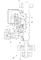
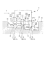
- FIG. 1 is a cross-sectional view showing a steam turbine 1 according to a first embodiment of the present invention.
- the steam turbine 1 is provided in a casing 10, a regulating valve 20 that adjusts the flow rate and pressure of the steam S flowing into the casing 10, and an inward rotation of the casing 10.
- the casing 10 has an internal space that extends in the direction of the rotation axis and is hermetically sealed.
- the casing 10 is a flow path for the steam S.
- a ring-shaped partition plate outer ring 11 through which the shaft body 30 is inserted is firmly fixed to the inner wall surface of the casing 10.
- the partition plate outer ring 11 is a “structure” in the present invention.
- the adjustment valve 20 includes an adjustment valve chamber 21 into which steam S flows from a plurality of boilers (not shown), a valve body 22 and a valve seat 23.
- a steam chamber 24 is formed on the downstream side of the regulating valve 20.
- the shaft body 30 includes a shaft main body 31 and a plurality of disks 32 extending in the radial direction from the outer periphery of the shaft main body 31.
- the shaft body 30 transmits rotational energy to a machine such as a generator (not shown).
- a plurality of the stationary blades 40 are arranged so as to surround the shaft body 30, and are arranged radially about the shaft body 30.
- the plurality of stationary blades 40 form an annular stationary blade group and are held by the partition plate outer ring 11 described above.
- the inner side in the radial direction of the stationary blade 40 is connected by a ring-shaped hub shroud 41 through which the shaft body 30 is inserted, and the distal end portion of the stationary blade 40 forms a radial gap with respect to the shaft body 30.
- Six annular stator blade groups including a plurality of stator blades 40 are formed at intervals in the rotation axis direction. The annular stator blade group converts the pressure energy of the steam S into velocity energy and guides the steam S to the moving blade 50 adjacent to the downstream side.
- a plurality of rotor blades 50 are firmly attached to the outer peripheral portion of the disk 32 included in the shaft body 30.
- the plurality of rotor blades 50 are arranged radially about the shaft body 30.
- the plurality of rotor blades 50 respectively constitute an annular rotor blade group on the downstream side of each annular stator blade group.
- the moving blade 50 is a “blade” in the present invention.
- the annular stator blade group and the annular rotor blade group are one set and one stage. Therefore, the steam turbine 1 is configured in six stages.
- a tip shroud 51 extending in the circumferential direction is provided at the tip of the moving blade 50.
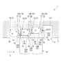
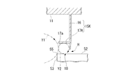
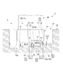
- FIG. 2 is an enlarged cross-sectional view of a main part I in FIG.
- the tip shroud 51 provided at the tip of the moving blade (blade) 50 is arranged to face the partition plate outer ring (structure) 11 with a gap in the radial direction of the casing 10.
- the chip shroud 51 includes a step portion 52 (52A to 52C) having a step surface 53 (53A to 53C) and protruding toward the partition plate outer ring 11 side.
- the chip shroud 51 includes three step units 52 (52A to 52C).
- the step portion 52 (52A to 52C) has a surface facing the partition plate outer ring 11, and a step adjacent to the surface.
- the three step portions 52A to 52C have projecting heights from the rotor blade 50 toward the partition plate outer ring 11 as they go from the upstream side to the downstream side in the rotational axis direction of the shaft body 30 (hereinafter referred to as “axial direction”). It arrange
- the step surface 53 ⁇ / b> A is an end surface on the upstream side in the axial direction of the chip shroud 51.
- the step portions 52A and 52B are connected via a step surface 53B, and the step portions 52B and 52C are connected via a step surface 53C.
- the edge portion on the side of the partition plate outer ring 11 on the step surface 53 (53A to 53C) is referred to as the edge portion 55 of the step portion 52 (52A to 52C).
- annular groove (annular recess) 11 a extending in the circumferential direction of the casing 10 (see FIG. 1) is formed in the partition plate outer ring 11 at a portion corresponding to the chip shroud 51.
- a tip shroud 51 is accommodated in the annular groove 11a.
- Three seal fins 15 (15A to 15C) extending radially inward toward the tip shroud 51 are provided on the groove bottom surface 11b of the annular groove 11a of the partition plate outer ring 11.
- the annular groove 11 a is formed in a step shape so that the downstream side is deeper than the upstream side in the axial direction of each seal fin 15. That is, the groove bottom surface 11b of the annular groove 11a is formed in a stepped shape so as to gradually move away from the moving blade 50 from the upstream side toward the downstream side in the axial direction.
- the seal fins 15 are provided to extend from the groove bottom surface 11b so as to correspond to the step portions 52 (52A to 52C) on a one-to-one basis. More specifically, the seal fins 15 (15A to 15C) are provided to face a portion on the upstream side in the axial direction of the step portion 52 (52A to 52C) (in the vicinity of the end edge portion 55). Further, the step surface 53 (53A to 53C) is formed slightly upstream from the seal fin 15 (15A to 15C) in the axial direction.
- Each of the seal fins 15A to 15C has a fin body portion 16 that forms a minute gap H (H1 to H3) in the radial direction between the seal portion 15A and the step portion 52 (52A to 52C), and a shaft of the minute gap H (H1 to H3). And a space restricting portion 17 that restricts the space on the upstream side in the direction.
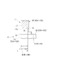
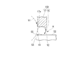
- FIG. 3 is an enlarged sectional view of the seal fin 15 (15A to 15C).
- the fin main body 16 is formed in a shape with a sharp tip.
- the fin body portion 16 is closer to the step portion 52 (52A to 52C) than the space limiting portion 17, and a minute gap H (H1 to H3) is formed between the fin body portion 16 and the step portion 52 (52A to 52C).
- the length of the fin body portion 16 in the radial direction is approximately the same as the size (radial direction) of the minute gap H (H1 to H3).
- the size of the minute gap H determines the contact between the fin main body portion 16 and the step portion 52 in consideration of the thermal elongation amount of the casing 10 and the moving blade 50, the centrifugal elongation amount of the moving blade 50, and the like. It is set to a minimum within a safe range that can be prevented.
- the minute gaps H1 to H3 are all the same size. However, these may be changed as needed.
- the space restricting portion 17 is formed to be thicker in the axial direction than the fin main body portion 16 of the seal fin 15 (15A to 15C).
- the space restricting portion 17 has an inner peripheral wall surface (rotary shaft direction wall surface) 17a extending in the axial direction.
- the inner peripheral wall surface 17a is formed in a surface facing the step portion 52 (52A to 52C), and is axial in a cross section (hereinafter sometimes referred to as “sectional view”) on a plane including a rotation axis. It is formed in a straight line extending.
- the inner peripheral wall surface 17a extends from the fin body portion 16 toward the upstream side in the axial direction.
- the fin main body portion 16 projects from the end portion on the downstream side in the axial direction of the inner peripheral wall surface 17a toward the step portion 52 (52A to 52C).
- the width of the inner peripheral wall surface 17a in the axial direction is approximately twice the minute gap H (H1 to H3).
- the length of the fin body portion 16 in the radial direction is substantially the same as the size of the minute gap H (H1 to H3) (the size in the radial direction)
- the inner peripheral wall surface 17a and the step portion 52 are provided.
- the distance from (52A to 52C) is approximately twice the minute gap H (H1 to H3).
- wheel 11 may be formed integrally, and may each be formed separately. Further, when the fin main body 16 and the space restricting portion 17 are separated, the fin main body 16 is attached to the distal end side (step portion 52 side) of the space restricting portion 17 extending from the groove bottom surface 11b. Alternatively, the space restricting portion 17 may be arranged along the fin main body portion 16 extending from the groove bottom surface 11b.
- the space restricting portion 17 restricts the space upstream in the axial direction of the fin body portion 16 in the radial direction, and forms a small cavity 18 between the step portion 52 (52A to 52C). That is, the small cavities 18 are formed between the inner peripheral wall surface 17a of the space restricting portion 17 and the step portions 52 (52A to 52C).
- the small cavity 18 is formed in a square shape whose one side is approximately twice the minute gap H (H1 to H3) in the cross section on the plane including the rotation axis.
- three cavities C are formed between the tip shroud 51 and a portion (annular groove 11 a) corresponding to the tip shroud 51 of the partition plate outer ring 11.
- the three cavities C (C1 to C3) are provided upstream of the seal fins 15 (15A to 15C) corresponding to the step portions 52 (52A to 52C) and the seal fins 15 (15A to 15C) in the axial direction.
- Each is formed between opposing partition walls.
- the partition in the first cavity C1 located on the most upstream side in the axial direction is formed by the inner wall surface 54 on the upstream side in the axial direction of the annular groove 11a. That is, the first cavity C ⁇ b> 1 is formed by the inner wall surface 54, the seal fin 15 ⁇ / b> A corresponding to the first step portion 52 ⁇ / b> A, and the groove bottom surface 11 b of the partition plate outer ring 11.
- the partition in the second cavity C2 is formed by seal fins 15A corresponding to the step portions 52A. That is, the second cavity C ⁇ b> 2 is formed by the seal fin 15 ⁇ / b> A, the seal fin 15 ⁇ / b> B, the step portion 52 ⁇ / b> A, and the groove bottom surface 11 b of the partition plate outer ring 11.
- the partition in the third cavity C3 is formed by seal fins 15B corresponding to the step portions 52B. That is, the third cavity C ⁇ b> 3 is formed by the seal fin 15 ⁇ / b> B, the seal fin 15 ⁇ / b> C, the step portion 52 ⁇ / b> B, and the groove bottom surface 11 b of the partition plate outer ring 11.
- the small cavities 18 are formed between the cavities C (C1 to C3) and the minute gaps H (H1 to H3), respectively.
- the space restricting portion 17 forms small cavities 18 between the cavities C (C1 to C3) and the minute gaps H (H1 to H3).
- the bearing portion 60 includes a journal bearing device 61 and a thrust bearing device 62, and supports the shaft body 30 in a rotatable manner. Therefore, the rotor blade 50 and the partition plate outer ring 11 can rotate relatively around the shaft body 30. Similarly, the stationary blade 40 and the shaft body 30 are relatively rotatable.
- the steam S that has flowed into the internal space of the casing 10 sequentially passes through each stage of the annular stator blade group and the annular rotor blade group.
- the pressure energy of the steam S is converted into velocity energy by the stationary blade 40.
- most of the steam S that has passed between the stationary blades 40 flows between the moving blades 50 that constitute the same stage, and the velocity energy of the steam S is converted into rotational energy by the moving blades 50.
- a rotational force is applied to the shaft body 30 by the rotational energy.
- a part (for example, several percent) of the steam S that has passed between the stationary blades 40 becomes so-called leaked steam that flows out from between the stationary blades 40 and then flows into the annular groove 11a.
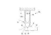
- the steam S that has flowed into the annular groove 11a first flows into the first cavity C1.
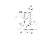
- the steam S that has flowed into the first cavity C1 collides with the stepped surface 53A of the step portion 52A, the direction of the flow thereof changes, and returns to the upstream side.
- the main vortex Y1 swirling counterclockwise (first direction) on the paper surface is generated.
- the steam S is separated from the main vortex Y1 and the main vortex Y1, and the flow direction of the steam S is changed to the radially outer side by the steam S flowing into the small cavity 18, and then again toward the inner peripheral wall surface 17a. Flowing radially outward.
- a contraction effect is generated that reduces the leakage flow of the steam S passing through the minute gap H1 between the fin main body portion 16 and the step portion 52A of the seal fin 15A. That is, as shown in FIG. 4, when the separation vortex Y2 is generated, a downflow that causes the velocity vector of the leakage flow to be directed radially inward occurs on the upstream side in the axial direction of the minute gap H1.
- the downflow has an inertial force directed radially inward immediately before the minute gap H1 (a position slightly shifted toward the upstream side in the axial direction), and thus passes through the minute gap H1 downstream in the axial direction.
- the effect of contracting the leakage flow radially inward occurs. As a result, the amount of leakage of the steam S through the minute gap H1 is reduced.
- the separation vortex Y2 is formed in a substantially perfect circle.
- both the width in the axial direction of the inner peripheral wall surface 17a and the interval between the inner peripheral wall surface 17a and the step portion 52A are approximately twice the minute gap H1
- the diameter of the separation vortex Y2 is smaller than the minute gap. It is approximately twice H1.
- the diameter of the separation vortex Y2 is approximately twice the minute gap H1 and the outer periphery thereof is in contact with the tip of the fin body portion 16, the position where the radial velocity component in the down flow of the separation vortex Y2 is maximized is the fin body. It substantially coincides with the tip (inner edge) of the portion 16. Accordingly, the downflow passes immediately before the minute gap H1 toward the radially inward side at the maximum speed, and it is considered that the contraction effect on the leakage flow is further increased.
- the separation vortex Y2 is generated in the small cavity 18 on the upstream side in the axial direction of each of the minute gaps H1 to H3 as shown in FIG.
- a contraction effect on the leakage flow of the steam S passing through the minute gaps H1 to H3 occurs, and the leakage amount is sequentially reduced.
- the step surface 53 in which the steam S flowing into the cavity C (C1 to C3) forms the end edge portion 55 of the step portion 52 (52A to 52C).
- the main vortex Y1 swirling in the first direction is generated by changing the flow direction and returning to the upstream side. Further, at the end edge portion 55 of the step surface 53 (53A to 53C), a part of the flow is separated from the main vortex Y1, so that a separation vortex Y2 swirling in the second direction opposite to the first direction is formed. Arise.
- the separation vortex Y2 As the separation vortex Y2 is generated, a contraction effect is generated that reduces the leakage flow passing through the minute gap H (H1 to H3) between the fin main body portion 16 and the step portion 52 (52A to 52C). Furthermore, since the small space 18 is formed between the cavity C (C1 to C3) and the minute gap H (H1 to H3) by the space restricting portion 17, the space is narrowed compared to the cavity C (C1 to C3). The flow of the separation vortex Y2 is strengthened in the small cavity 18. Therefore, the contraction effect by the separation vortex Y2 is sufficiently enhanced, and the leakage flow rate passing through the minute gap H (H1 to H3) can be further reduced.
- the inner peripheral wall surface 17a extending from the fin main body portion 16 to the upstream side in the axial direction is provided, the flow of the separation vortex Y2 is restricted by the inner peripheral wall surface 17a and the fin main body portion 16. Therefore, the flow of the separation vortex Y2 can be further enhanced, the contraction effect can be further enhanced, and the separation vortex Y2 can be stably maintained.
- the contraction effect by the separation vortex Y2 is obtained for each of the step portions 52 (52A to 52C), the leakage flow rate between the moving blade 50 and the corresponding partition plate outer ring 11 can be sufficiently reduced.
- the separation vortex Y2 is also generated in the small cavity 18 corresponding to the step portion 52A located on the most upstream side in the axial direction, so that the leakage flow rate between the moving blade 50 and the corresponding partition plate outer ring 11 is reduced. It can be reduced sufficiently.
- the seal fin 15 ⁇ / b> D has an inner peripheral wall surface 17 a that is smoothly connected to the fin main body portion 16 in a circular arc shape in a sectional view.
- the connection portion between the inner peripheral wall surface 17a and the fin main body portion 16 is recessed in an arc shape in a cross-sectional view.
- the connection portion between the inner peripheral wall surface 17a and the fin main body portion 16 is formed by, for example, fillet R processing.
- the inner peripheral wall surface 17a is connected to the fin main body portion 16 in an arc shape in a sectional view.
- the separation vortex Y2 flowing along the inner peripheral wall surface 17a can be smoothly flowed along the fin main body portion 16, and the restriction effect on the separation vortex Y2 can be strengthened. Therefore, the flow of the separation vortex Y2 can be further strengthened, the contraction effect can be further enhanced, and the separation vortex Y2 can be stably maintained.
- the seal fin 15 ⁇ / b> E has an inner peripheral wall surface 17 b that is recessed in an arc shape in a sectional view.
- the separation vortex Y2 flows in an arc shape in the sectional view along the inner peripheral wall surface 17b. Therefore, the flow direction of the separation vortex Y2 can be changed smoothly, and the restriction effect on the separation vortex Y2 can be strengthened. Therefore, the flow of the separation vortex Y2 can be further strengthened, the contraction effect can be further enhanced, and the separation vortex Y2 can be stably maintained.
- the seal fin 15 ⁇ / b> F has a fin body portion 16 ⁇ / b> A that extends obliquely toward the upstream side in the axial direction.
- the fin main body portion 16A extends obliquely toward the upstream side in the axial direction, and therefore, on the upstream side in the axial direction of the minute gap H, the separation vortex Y2 is directed toward the leakage flow flowing downstream in the rotational axis direction. Down flow. Therefore, in the vicinity of the distal end portion of the fin body portion 16A, the axial velocity component V X of the flow velocity V of the flow and leakage flow and down-flow of the separation vortex Y2 is joined is reduced.
- the seal fin 15H has an inner peripheral wall surface 17d that inclines so as to gradually go inward in the radial direction as it goes from the upstream side in the axial direction to the downstream side.
- the strong separation vortex Y2 is generated by smoothly guiding the steam S, which is separated from the main vortex Y1 at the edge 55 and flows into the small cavity 18 to the downstream side in the axial direction along the inner peripheral wall surface 17d. Can be generated. That is, since the separation vortex Y2 flowing along the inner peripheral wall surface 17d can smoothly flow along the fin main body portion 16, the strength of the flow of the separation vortex Y2 from the inner peripheral wall surface 17d toward the fin main body portion 16 is increased. Does not decrease. Therefore, a strong separation vortex Y2 can be generated, and the contraction effect can be further enhanced.
- the inner peripheral wall surface 17d may be formed in an arc shape in a sectional view like the inner peripheral wall surface 17b in FIG.
- the seal fin 15 ⁇ / b> I has a corner portion 17 e that is an end edge portion on the upstream side in the axial direction of the space limiting portion 17 and is formed in an arc shape in a cross-sectional view.
- the seal fin 15J has an end face 17f formed on the upstream side in the axial direction of the space restricting portion 17 and inclined so as to gradually go inward in the radial direction as it goes from the upstream side in the axial direction to the downstream side.
- the end surface 17f is provided in contact with the axially upstream side of the inner peripheral wall surface 17a.
- the main vortex Y1 flows along at least a part of the end face 17f, so that the flow of the main vortex Y1 can be prevented from being weakened.
- the flow separating from the main vortex Y1 at the edge 55 becomes stronger, so that the flow of the separation vortex Y2 can be strengthened.
- the seal fin 15 ⁇ / b> K has a space limiting portion 17 ⁇ / b> A that extends from the side surface of the fin main body portion 16 toward the upstream side in the axial direction.
- the fin body portion 16 is directly connected to the partition plate outer ring 11 and extends from the partition plate outer ring 11 toward the step portion 52.
- the space restricting portion 17A is a wall body extending along the axial direction.
- the space between the space restricting portion 17A and the step portion 52 is approximately twice the minute gap H. Since only the fin body portion 16 supports the space limiting portion 17A, the rigidity of the seal fin 15K is low.
- the seal fin 15 ⁇ / b> L is provided on the upstream side in the axial direction of the fin body portion 16 and the fin body portion 16, and extends toward the step portion 52.
- a fin-like space restricting portion (radial wall) 17B that forms a gap larger than the minute gap H.
- a separation vortex Y2 and a supplementary vortex Y3 that is adjacent to the separation vortex Y2 in the radial direction and pivots in the first direction that is the pivot direction of the main vortex Y1 are formed in the small cavity 18.
- the auxiliary vortex Y3 By forming the auxiliary vortex Y3, the shape of the separation vortex Y2 is adjusted to a substantially perfect circle.
- the seal fin 15L since there is no inner peripheral wall surface (a wall surface facing the step portion 52) that restricts the flow of the separation vortex Y2, the contact flow resistance of the separation vortex Y2 is reduced. Therefore, the flow of the separation vortex Y2 is strengthened, and the contraction effect can be further enhanced.
- FIG. 13 is a cross-sectional view showing the steam turbine 2 and corresponding to FIG. 2 of the first embodiment. Components similar to those in FIGS. 1 to 12 are denoted by the same reference numerals, and description thereof is omitted.
- simulation is performed based on the knowledge that there is a condition for effectively obtaining the contracted flow effect, and each component of the steam turbine 2 is set according to the obtained condition.
- the axial distance between the fin body portion 16 and the end edge portion 55 on the upstream side in the axial direction of each step portion 52 corresponding to each fin body portion 16 that is, the fin body portion 16 and the step.
- the distance L satisfies the following formula (1). 0.7H ⁇ L ................ alone (1)
- the distance L is the axial width of the small cavity 18.
- H1 to H3 all have the same size, and therefore H represents H1 to H3 as a representative.
- FIG. 14 is a graph showing a simulation result.
- the horizontal axis in FIG. 14 indicates the size (length) of the distance L, and the vertical axis indicates the turbine efficiency change and the leak amount change rate.
- the magnitude with respect to the turbine efficiency and leak flow rate in a general step fin structure is shown.
- both the horizontal axis and the vertical axis in FIG. 14 are general equidistant scales.
- the distance L is preferably set so as to satisfy the following expression (1). 0.7H ⁇ L . .
- the width of the small cavity 18 (the width in the axial direction) is sufficiently secured, so that the separation vortex Y2 is likely to occur at the end edge portion 55. For this reason, the down flow of the separation vortex Y2 on the upstream side in the axial direction of the fin body portion 16 is sufficiently formed. Therefore, it is possible to sufficiently obtain a contraction effect on the leakage flow due to the downflow. Since the leakage flow rate increases, as shown in FIG. 14, the leak rate change rate is low ( ⁇ side). Further, since the turbine efficiency is improved by reducing the leakage flow rate, the turbine efficiency change is high (+ side).
- FIG. 15 is a graph showing a simulation result.
- FIG. 15 shows a comparison result of the turbine efficiency change and the leak rate change rate in the turbine provided with the small cavity 18 in which the distance L is set to 0.7H or more and the turbine not provided. As shown in FIG. 15, the turbine with the small cavity 18 has a smaller leak amount and higher turbine efficiency than the turbine without the small cavity 18.
- the distance L (L1 to L3) is set so as to satisfy Expression (1). Accordingly, in each small cavity 18, the positional relationship between the step portions 52A to 52C and the corresponding fin main body portion 16 satisfies the expression (1), so that the contraction effect by the separation vortex Y2 is sufficient. As a result, the leakage flow rate is significantly reduced as compared with the prior art. Therefore, in the steam turbine 2 provided with the above-described seal structure, the leakage flow rate is further reduced, and the performance can be further improved.
- FIG. 16 is a cross-sectional view showing the steam turbine 3 and corresponding to FIG. 2 of the first embodiment. Components similar to those in FIGS. 1 to 15 are denoted by the same reference numerals, and description thereof is omitted.
- the third embodiment shown in FIG. 16 differs from the first embodiment in the following points.
- the step portion 52 (52A to 52C) is formed in the tip shroud 51 provided at the tip of the moving blade 50, and the seal fin 15 (15A to 15A to 15A) is formed on the partition plate outer ring 11 fixed to the casing 10. 15C).
- the step portion 52 is formed on the partition plate outer ring 11, and the seal fin 15 is provided on the chip shroud 51.
- two step portions 52 are formed on the groove bottom surface 11 b of the annular groove 11 a formed in the partition plate outer ring (structure) 11.
- the two step portions 52 are a step portion 52D having a step surface 53D and a step portion 52E having a step surface 53E and provided on the downstream side in the axial direction of the step portion 52D.
- the step portions 52D and 52E are arranged so that the protruding height toward the rotor blade 50 side gradually increases as it proceeds downstream in the axial direction.
- the tip shroud 51 provided at the tip of the moving blade (blade) 50 is provided with three seal fins 15 (15M to 15O) extending radially outward toward the groove bottom surface 11b. ing.
- the seal fin 15M on the most upstream side in the axial direction does not include the space restricting portion 17 but includes only the fin main body portion 16.
- the seal fin 15M extends toward the groove bottom surface 11b located on the upstream side in the axial direction of the step portion 52D, and forms a minute gap in the radial direction between the seal fin 15M and the groove bottom surface 11b.
- Each of the seal fins 15N and 15O includes a fin main body portion 16 and a space limiting portion 17.
- the seal fins 15N and 15O extend corresponding to the step portions 52D and 52E, respectively.
- Each fin main body portion 16 of the seal fins 15N and 15O has minute gaps H (H4 and H5) formed in the radial direction between the corresponding step portions 52D and 52E. Further, in each of the seal fins 15N and 15O, the space restricting portion 17 restricts the space on the upstream side in the axial direction of the fin body portion 16 in the radial direction and forms the small cavity 18 between the step portions 52D and 52E. is doing.
- each minute gap H takes into account the thermal elongation amount of the casing 10 and the moving blade 50, the centrifugal elongation amount of the moving blade 50, and the like.
- 16 and the step portion 52 are set to a minimum within a safe range in which the contact can be prevented.
- H4 and H5 are set to the same size. However, these may be changed as needed.
- cavities C (C4, C5) are formed between the tip shroud 51 and a portion (annular groove 11a) corresponding to the tip shroud 51 of the partition plate outer ring 11.
- the cavities C (C4, C5) include seal fins 15 (15N, 15O) corresponding to the respective step portions 52 (52D, 52E), and the upstream side in the axial direction with respect to these seal fins 15. Formed between the opposing partition walls.
- the partition wall is formed by seal fins 15M. That is, the first cavity C4 is formed between the seal fin 15M, the seal fin 15N, the tip shroud 51, and the partition plate outer ring 11 (groove bottom surface 11b).
- the partition is formed by seal fins 15N. That is, the second cavity C5 is formed between the seal fin 15N, the seal fin 15O, the tip shroud 51, and the partition plate outer ring 11 (groove bottom surface 11b).
- the contraction effect on the leakage flow due to the separation vortex Y2 is obtained. It becomes sufficiently high, and the leakage flow rate is significantly reduced compared to the conventional case. Therefore, in the steam turbine 3 having the above-described seal structure, the leakage flow rate is further reduced, and the performance can be further improved.
- the leakage flow rate can be reduced by the contraction effect in each small cavity 18. Therefore, the leakage flow rate can be further reduced as a whole.
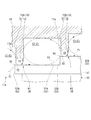
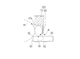
- FIG. 17 is an enlarged cross-sectional view illustrating a portion corresponding to the main part J in FIG. 1 of the first embodiment, and corresponds to FIG. 2 of the first embodiment.
- Components similar to those in FIGS. 1 to 16 are denoted by the same reference numerals, and description thereof is omitted.
- the fourth embodiment shown in FIG. 17 is different from the first embodiment in the following points.
- the “blade” according to the present invention is used as the moving blade 50, and the step portion 52 (52 A to 52 C) is formed in the tip shroud 51 provided at the tip of the moving blade 50.
- Such a “structure” is a partition plate outer ring 11, and seal fins 15 (15 A to 15 C) are provided on the partition plate outer ring 11.
- the “blade” according to the present invention is the stationary blade 40
- the step portion 52 is formed at the tip of the stationary blade 40
- the “structure” according to the present invention is the shaft body 30, Seal fins 15 are provided on the shaft body 30.
- three step portions 52 are formed in the hub shroud 41 extending in the circumferential direction at the tip of the stationary blade 40.
- the three step portions 52F to 52H are arranged such that the projecting height from the stationary blade 40 toward the shaft body 30 gradually increases from the upstream side in the axial direction of the shaft body 30 toward the downstream side.
- the step surfaces 53 (53F to 53H) forming the steps of the step portions 52 (52F to 52H) are formed facing the upstream side in the axial direction.
- annular groove 33 extending in the circumferential direction is formed at a portion corresponding to the hub shroud 41 of the shaft body 30.
- the annular groove 33 is formed between the disks 32 and 32 of the shaft body 30.
- a hub shroud 41 is accommodated in the annular groove 33.
- three seal fins 15 (15P to 15R) extending radially outward toward the hub shroud 41 are provided on the groove bottom surface 33a of the annular groove 33.
- the annular groove 33 is formed in a step shape so that the downstream side is deeper than the upstream side in the axial direction of each seal fin 15. That is, the groove bottom surface 33 a of the annular groove 33 is formed in a step shape so as to gradually move away from the stationary blade 40 as it goes from the upstream side in the axial direction to the downstream side.
- Each of the seal fins 15 (15P to 15R) includes a fin body portion 16 and a space limiting portion 17.
- the cage seal fins 15 (15P to 15R) extend from the groove bottom surface 33a so as to correspond one-to-one to the step portions 52 (52F to 52H). More specifically, the seal fins 15 (15P to 15R) are provided to face a portion on the upstream side in the axial direction of the step portion 52 (52F to 52H) (in the vicinity of the end edge portion 55). Further, the step surface 53 (53F to 53H) of the step portion 52 (52F to 52H) is formed slightly upstream from the seal fin 15 (15P to 15R) in the axial direction.
- minute gaps H are formed in the radial direction between the fin body portion 16 and the step portions 52 (52F to 52H).
- the space restricting portion 17 restricts the space on the upstream side in the axial direction of the fin body portion 16 in the radial direction, and forms a small cavity 18 between the step portions 52 (52F to 52H).
- a cavity C (C6 to C8) is formed between the hub shroud 41 and a portion (annular groove 33) corresponding to the hub shroud 41 of the shaft body 30.
- the cavities C (C6 to C8) include seal fins 15 corresponding to the respective step portions 52 and partition walls (the inner wall surface 34 or the shaft on the upstream side in the axial direction of the annular groove 33) facing the seal fins 15 on the upstream side in the axial direction. It is formed between other seal fins 15) adjacent to the upstream side in the direction.
- the small cavities 18 are formed between the cavities C (C6 to C8) and the minute gaps H (H6 to H8), respectively.
- the contraction effect on the leakage flow due to the separation vortex Y2 is sufficient.
- the leakage flow rate is significantly reduced as compared with the prior art. Therefore, in the steam turbine 4 having the above-described seal structure, the leakage flow rate is further reduced, and the performance can be further improved.
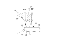
- FIG. 18 is an enlarged cross-sectional view showing a portion corresponding to the main part J in FIG. 1 of the first embodiment, and corresponds to FIG. 17 of the fourth embodiment.
- the fifth embodiment shown in FIG. 18 differs from the fourth embodiment in the following points.
- the step portion 52 (52F to 52H) is formed in the hub shroud 41 provided at the tip of the stationary blade (blade) 40, and the seal fin 15 (15P to 15P) is attached to the shaft body (structure) 30. 15R).
- the step portion 52 (52I, 52J) is formed in the shaft body (structure) 30, and the seal fin 15 (15S to 15U) is provided in the hub shroud 41.
- a step portion 52I having a step surface 53I and a step surface 53J are provided on the groove bottom surface 33a of the annular groove 33 formed in the shaft body (structure) 30, and the step is performed.
- the step part 52J provided in the axial direction downstream of the part 52I is formed.
- the step portions 52I and 52J are arranged so that the protruding height toward the stationary blade 40 side gradually increases as it proceeds downstream in the axial direction.
- the hub shroud 41 of the stationary blade (blade) 40 is provided with three seal fins 15 (15S to 15U) extending radially inward toward the groove bottom surface 33a.
- the seal fin 15S on the most upstream side in the axial direction includes only the fin main body portion 16 without including the space limiting portion 17.
- the seal fin 15S extends to the groove bottom surface 33a located on the upstream side in the axial direction of the step portion 52I, and forms a minute gap in the radial direction between the seal fin 15S and the groove bottom surface 33a.
- Each of the seal fins 15T and 15U includes a fin body portion 16 and a space restriction portion 17. Seal fins 15T and 15U extend to step portions 52I and 52J, respectively.
- Each fin main body portion 16 of the seal fins 15T and 15U has minute gaps H (H9 and H10) formed in the radial direction between the corresponding step portions 52I and 52J.
- the space restricting portion 17 restricts the space on the upstream side in the axial direction of the fin body portion 16 in the radial direction and forms a small cavity 18 between the step portions 52I and 52J. Yes.
- cavities C are formed between the hub shroud 41 and a portion (annular groove 33) corresponding to the hub shroud 41 of the shaft body 30.
- the partition plate outer ring 11 provided in the casing 10 is the “structure” in the present invention, but the casing 10 itself is not provided with the partition plate outer ring 11.
- the “structure” may be used. That is, the “structure” of the present invention may be any member as long as it surrounds the moving blade 50 and forms a flow path through which fluid passes.
- the other side (for example, the groove bottom surface 11b, 33a) provided with the seal fin 15 is formed in a step shape corresponding to the step portion 52 on one side.
- the diameter from the rotating shaft to the other side may be formed to the same diameter.
- seal fins 15D to 15L described as modifications of the first embodiment may be used.
- a plurality of cavities C and small cavities 18 are formed (two or three in the above-described embodiment), but the number of cavities C and small cavities 18 is arbitrary and one. There may be four or more.
- the seal fins 15 and the step portions 52 do not necessarily have to correspond one-to-one, and these numbers can be arbitrarily designed.
- a plurality of seal fins 15 may be extended with respect to one step part 52.
- the present invention is applied to the final stage moving blade 50 and the stationary blade 40, but the present invention may be applied to other stages of the moving blade 50 and the stationary blade 40.
- the present invention is applied to a condensing steam turbine.
- the present invention is applied to other types of steam turbines, for example, turbine types such as a two-stage extraction turbine, an extraction turbine, and an air-mixing turbine. You may apply.
- the present invention is applied to a steam turbine, but the present invention may be applied to a gas turbine.
Landscapes
- Engineering & Computer Science (AREA)
- General Engineering & Computer Science (AREA)
- Mechanical Engineering (AREA)
- Turbine Rotor Nozzle Sealing (AREA)
- Sealing Using Fluids, Sealing Without Contact, And Removal Of Oil (AREA)
Abstract
Description
このようなシール構造によれば、ステップ部とシールフィンとの隙間を通り抜けた漏れ流れがステップ部の端縁部を形成する段差面に衝突し、流動抵抗が増大することにより、漏洩流量が低減される。
この場合には、回転軸方向壁面とフィン本体部とによって剥離渦の流れが規制される。したがって、剥離渦の流れがさらに強められ、縮流効果をさらに高めることができる。
この場合には、回転軸を含む面での断面において、回転軸方向壁面に沿って円弧状に剥離渦が流れる。したがって、剥離渦の流れ方向をスムーズに変化させることができ、剥離渦への規制効果を強めることができる。よって、剥離渦の流れがさらに強められ、縮流効果をさらに高めることができる。
この場合には、回転軸を含む面での断面において、回転軸方向壁面からフィン本体部に沿って円弧状に剥離渦が流れる。したがって、回転軸方向壁面に沿って流れる剥離渦をスムーズにフィン本体部に沿わせて流すことができ、剥離渦への規制効果を強めることができる。よって、剥離渦の流れがさらに強められ、縮流効果をさらに高めることができる。
この場合には、上記微小隙間の回転軸方向上流側において、回転軸方向下流側に流れる漏れ流れに向かうように剥離渦のダウンフローが流れる。そのため、フィン本体部の先端部近傍において、漏れ流れと剥離渦のダウンフローとが合流した流れにおける流速の回転軸方向速度成分VXが小さくなる。フィン本体部の先端近傍において、上記合流した流れにおける流速の径方向速度成分をVRとすると、VX/VRが0に近づくほど剥離渦の縮流効果が大きくなるので、縮流効果をさらに高めることができる。
この場合には、小キャビティ内において、剥離渦と、この剥離渦に径方向に隣接し主渦の旋回方向と同一の方向に旋回する補渦とが形成される。したがって、剥離渦の接触流動抵抗が軽減される。よって、剥離渦の流れが強められ、縮流効果を高めることができる。
0.7H≦L …………………(1)
この場合には、剥離渦による縮流効果は、端縁部の位置(フィン本体部からの距離L)と微小隙間Hの大きさとの関係によって変化する。後述するシミュレーション結果に基づき、式(1)を満足するようにこれらの関係を設定することにより、剥離渦による縮流効果が十分に高められ、漏洩流量をより低減できる。
この場合には、剥離渦による縮流効果が各ステップ部毎に得られ、ブレードとこれに対向する構造体との間の漏洩流量を十分に低減できる。
この場合には、回転軸方向最上流側に位置するステップ部においても、上記の剥離渦による縮流効果が得られ、ブレードとこれに対向する構造体との間の漏洩流量を十分に低減できる。
(第一実施形態)
図1は、本発明の第一実施形態に係る蒸気タービン1を示す断面図である。
蒸気タービン1は、ケーシング10と、ケーシング10に流入する蒸気Sの流量と圧力を調整する調整弁20と、ケーシング10の内方に回転可能に設けられ、図示しない発電機等の機械に駆動力(回転エネルギー)を伝達する軸体30と、ケーシング10に設けられた静翼40と、軸体30に設けられた動翼50と、軸体30を回転軸回りに回転可能に支持する軸受部60と、を主な要素として備えている。
複数の静翼40からなる環状静翼群は、回転軸方向に間隔をあけて六つ形成されている。上記環状静翼群は、蒸気Sの圧力エネルギーを速度エネルギーに変換すると共に、下流側に隣り合う動翼50側に蒸気Sを案内する。
図2に示すように、動翼(ブレード)50の先端部に設けられているチップシュラウド51は、ケーシング10の径方向において、仕切板外輪(構造体)11と隙間を空けて対向して配置されている。チップシュラウド51は、段差面53(53A~53C)を有して仕切板外輪11側に突出する、ステップ部52(52A~52C)を備えている。
仕切板外輪11の環状溝11aにおける溝底面11bには、チップシュラウド51に向けて径方向内方側に延出する三つのシールフィン15(15A~15C)が設けられている。環状溝11aは、各シールフィン15の軸方向上流側に比べて下流側が深くなるように段状に形成されている。すなわち、環状溝11aの溝底面11bは、軸方向上流側から下流側に向かうに従い、動翼50から次第に離れるように段状に形成されている。
図3に示すように、フィン本体部16は、先端部が尖った形状に形成されている。フィン本体部16は、空間制限部17よりもステップ部52(52A~52C)に近接しており、ステップ部52(52A~52C)との間に微小隙間H(H1~H3)を形成している。フィン本体部16の径方向における長さは、微小隙間H(H1~H3)の大きさ(径方向)と略同程度となっている。微小隙間H(H1~H3)の大きさは、ケーシング10や動翼50の熱伸び量、動翼50の遠心伸び量等を考慮した上で、フィン本体部16とステップ部52との接触を防止できる安全な範囲内で、最小に設定されている。なお、本実施形態では、各微小隙間H1~H3は全て同じ大きさとなっている。ただし、必要に応じて、これらを適宜に変えてもよい。
内周壁面17aの軸方向での幅は、微小隙間H(H1~H3)の略二倍である。また、フィン本体部16の径方向における長さが微小隙間H(H1~H3)の大きさ(径方向の大きさ)と略同程度となっているために、内周壁面17aとステップ部52(52A~52C)との間隔は、微小隙間H(H1~H3)の略二倍である。
なお、フィン本体部16,空間制限部17及び仕切板外輪11は、一体に形成してもよいし、それぞれ別体に形成してもよい。また、フィン本体部16と空間制限部17とを別体にした場合には、フィン本体部16を、溝底面11bから延在する空間制限部17の先端側(ステップ部52側)に取り付けてもよいし、空間制限部17を、溝底面11bから延びるフィン本体部16に沿うように配置してもよい。
三つのキャビティC(C1~C3)は、各ステップ部52(52A~52C)に対応した各シールフィン15(15A~15C)と、シールフィン15(15A~15C)に対して軸方向上流側で対向する隔壁との間にそれぞれ形成されている。
また、第三のキャビティC3における上記隔壁は、ステップ部52Bに対応するシールフィン15Bによって形成されている。すなわち、シールフィン15Bと、シールフィン15Cと、ステップ部52Bと、仕切板外輪11の溝底面11bとにより、第三のキャビティC3が形成されている。
なお、小キャビティ18は、各キャビティC(C1~C3)と微小隙間H(H1~H3)との間にそれぞれ形成されている。換言すれば、空間制限部17は、各キャビティC(C1~C3)と微小隙間H(H1~H3)との間に、それぞれ小キャビティ18を形成している。
まず、調整弁20(図1参照)を開状態とすると、図示しないボイラから蒸気Sがケーシング10の内部空間に流入する。
内周壁面17a(図3参照)によって径方向外方側の空間が制限されているために、径方向外方へ向かう蒸気Sの散逸が制限される。また、内周壁面17aによって軸方向下流側への蒸気Sの流れが生じるように規制されるために、剥離渦Y2の流れがより強められる。
すなわち、図4に示すように、剥離渦Y2が生じることにより、微小隙間H1の軸方向上流側において、上記漏れ流れの速度ベクトルを径方向内方側に向けさせるダウンフローが生じる。上記ダウンフローは、微小隙間H1の直前(軸方向上流側に僅かにずれた位置)で径方向内方側に向う慣性力を有しているため、微小隙間H1を軸方向下流側に通り抜ける上記漏れ流れを径方向内方側に縮める効果(縮流効果)が生じる。結果として、蒸気Sの微小隙間H1を介した漏洩量が低減する。
また、内周壁面17aの軸方向での幅と、内周壁面17a及びステップ部52Aの間隔とのいずれもが、微小隙間H1の略2倍であることから、剥離渦Y2の直径は微小隙間H1の略2倍となる。剥離渦Y2の直径が微小隙間H1の略2倍であり、その外周がフィン本体部16の先端に接する場合、剥離渦Y2のダウンフローにおける径方向の速度成分が最大になる位置が、フィン本体部16の先端(内端縁)に略一致する。したがって、上記ダウンフローが微小隙間H1の直前を径方向内方側に向かって最大の速度で通過するため、漏れ流れに対する縮流効果が更に大きくなると考えられる。
すなわち、剥離渦Y2が、図2に示すように、微小隙間H1~H3のそれぞれの軸方向上流側における小キャビティ18に生じる。各剥離渦Y2が生じることにより、微小隙間H1~H3をそれぞれ通り抜ける蒸気Sの漏れ流れに対する縮流効果が生じ、漏洩量が順次低減される。
なお、図5から図12において、図1から図4と同様の構成要素については、同一の符号を付して説明を省略する。
この変形例では、内周壁面17aがフィン本体部16に対して断面視において円弧状に接続されているので、内周壁面17aからフィン本体部16に沿って断面視において円弧状に剥離渦Y2が流れる。したがって、内周壁面17aに沿って流れる剥離渦Y2をスムーズにフィン本体部16に沿わせて流すことができ、剥離渦Y2への規制効果を強めることができる。よって、剥離渦Y2の流れがさらに強められ、縮流効果をさらに高めることができると共に、剥離渦Y2を安定的に維持できる。
この変形例では、内周壁面17bが断面視において円弧状に窪んでいるので、内周壁面17bに沿って断面視において円弧状に剥離渦Y2が流れる。したがって、剥離渦Y2の流れ方向をスムーズに変化させることができ、剥離渦Y2への規制効果を強めることができる。よって、剥離渦Y2の流れがさらに強められ、縮流効果をさらに高めることができると共に、剥離渦Y2を安定的に維持できる。
この変形例では、フィン本体部16Aが軸方向上流側に向けて斜めに延びているので、微小隙間Hの軸方向上流側において、回転軸方向下流側に流れる漏れ流れに向かうように剥離渦Y2のダウンフローが流れる。そのため、フィン本体部16Aの先端部近傍において、漏れ流れと剥離渦Y2のダウンフローとが合流した流れにおける流速Vの軸方向速度成分VXが小さくなる。フィン本体部16Aの先端部近傍において、流速Vの径方向速度成分をVRとすると、VX/VRが0に近づくほど剥離渦Y2の縮流効果が大きくなるので、縮流効果をさらに高めることができる。
なお、フィン本体部16Aの少なくとも先端側の一部が、軸方向上流側に向けて斜めに延在していれば、縮流効果を高めることが可能である。
この変形例では、端縁部55で主渦Y1から剥離して小キャビティ18に流入した蒸気Sを、内周壁面17dに沿わせてスムーズに軸方向下流側まで導くことにより、強い剥離渦Y2を発生させることができる。すなわち、内周壁面17dに沿って流れる剥離渦Y2が、スムーズにフィン本体部16に沿って流れることができるため、内周壁面17dからフィン本体部16に向かう剥離渦Y2の流れの強さが減少しない。したがって、強い剥離渦Y2を発生でき、縮流効果をさらに高めることができる。
なお、内周壁面17dを図6における内周壁面17bのように、断面視において円弧状に形成してもよい。
この変形例では、端縁部55で主渦Y1から剥離した蒸気Sが小キャビティ18に流入した後に、角部17eで主渦Y1からその一部がさらに剥離することを防止できる。そのため、主渦Y1の流れが弱められず、結果的に端縁部55で主渦Y1から剥離する流れが強くなる。したがって、剥離渦Y2の流れを強めることができる。
この変形例では、主渦Y1が端面17fの少なくとも一部に沿って流れるので、主渦Y1の流れが弱められることを防止できる。結果的に端縁部55で主渦Y1から剥離する流れが強くなるため、剥離渦Y2の流れを強めることができる。
この変形例では、動翼50が偶発的に径方向外方側に変位してシールフィン15Kに接触したとしても、シールフィン15Kの剛性が低いために、シールフィン15Kが容易に座屈する。そのため、動翼50及び仕切板外輪11が損傷することを抑制できる。
この変形例では、小キャビティ18内において、剥離渦Y2と、剥離渦Y2に径方向に隣接し主渦Y1の旋回方向である第一方向に旋回する補渦Y3とが形成される。補渦Y3が形成されることにより、剥離渦Y2の形状は略真円に整えられる。また、シールフィン15Lにおいては、剥離渦Y2の流れを規制する内周壁面(ステップ部52に対向する壁面)が存在しないので、剥離渦Y2の接触流動抵抗が軽減される。したがって、剥離渦Y2の流れが強められ、縮流効果をさらに高めることができる。
次に、本発明の第二実施形態に係る蒸気タービン2を図13に基づいて説明する。
図13は、蒸気タービン2を示す断面図であって、第一実施形態の図2に対応する図である。 なお、図1~図12と同様の構成要素については、同一の符号を付してその説明を省略する。
図13に示すように、フィン本体部16と、各フィン本体部16に対応する各ステップ部52の軸方向上流側における端縁部55との間の軸方向距離(すなわちフィン本体部16と段差面53との間の軸方向距離)をL(L1~L3)とすると、距離Lが以下の式(1)を満足している。
0.7H≦L …………………(1)
距離Lは、小キャビティ18における軸方向の幅となっている。
また、本実施形態では、H1~H3は全て同じ大きさとなっているため、HはH1~H3を代表して表している。
図13に示した距離Lと、タービン効率変化及びリーク量変化率との関係についてのシミュレーション結果を以下に説明する。
0.7H≦L …………………(1)
一方、式(1)を満足すれば、小キャビティ18の幅(軸方向の幅)が十分に確保されるため、端縁部55で剥離渦Y2が生じ易くなる。このため、フィン本体部16の軸方向上流側における剥離渦Y2のダウンフローが十分に形成される。したがって、ダウンフローによる漏れ流れに対する縮流効果を十分に得ることができる。漏洩流量が多くなるため、図14に示すように、リーク量変化率が低く(-側)なる。また、漏洩流量が少なくなることによりタービン効率は向上するため、タービン効率変化は高く(+側)なる。
図15に示すように、小キャビティ18有りのタービンは、小キャビティ18無しのタービンに比べ、リーク量は小さく、タービン効率は高い。
したがって、各小キャビティ18では、各ステップ部52A~52Cとこれに対応するフィン本体部16との間の位置関係が式(1)を満足しているため、剥離渦Y2による縮流効果が十分に高くなり、漏洩流量が従来に比べ格段に低減される。よって、上記シール構造を備えた蒸気タービン2においては、漏洩流量がより低減され、その性能を更に向上できる。
次に、本発明の第三実施形態に係る蒸気タービン3を図16に基づいて説明する。
図16は、蒸気タービン3を示す断面図であって、第一実施形態の図2に対応する図である。なお、図1~図15と同様の構成要素については、同一の符号を付してその説明を省略する。
また、シールフィン15N,15Oは、いずれもフィン本体部16と空間制限部17とを備えている。シールフィン15N,15Oは、それぞれステップ部52D,52Eに対応して延出している。シールフィン15N,15Oの各フィン本体部16は、対応するステップ部52D,52Eとの間に微小隙間H(H4,H5)をそれぞれ径方向に形成している。また、シールフィン15N,15Oのそれぞれにおいて、空間制限部17は、フィン本体部16の軸方向上流側の空間を径方向に制限して、ステップ部52D,52Eとの間に小キャビティ18を形成している。
キャビティC(C4,C5)は、第一実施形態と同様に、各ステップ部52(52D,52E)に対応したシールフィン15(15N,15O)と、これらシールフィン15に対して軸方向上流側で対向する隔壁との間に形成されている。
また、第二のキャビティC5では、上記隔壁は、シールフィン15Nによって形成されている。すなわち、シールフィン15Nと、シールフィン15Oと、チップシュラウド51と、仕切板外輪11(溝底面11b)との間に、第二のキャビティC5が形成されている。
小キャビティ18は、各キャビティC(C4,C5)と微小隙間H(H4,H5)との間にそれぞれ形成されている。
次に、本発明の第四実施形態に係る蒸気タービン4を図17に基づいて説明する。
図17は、第一実施形態の図1における要部Jに相当する部分を示す拡大断面図であり、第一実施形態の図2に対応する図である。
なお、図1~図16と同様の構成要素については、同一の符号を付してその説明を省略する。
三つのステップ部52F~52Hは、軸体30の軸方向上流側から下流側に向かうに従い、静翼40から軸体30に向かう突出高さが次第に高くなるように配設されている。ステップ部52(52F~52H)の段差を形成する段差面53(53F~53H)は、軸方向上流側を向いて形成されている。
シールフィン15(15P~15R)のそれぞれにおいては、フィン本体部16がステップ部52(52F~52H)との間に微小隙間H(H6~H8)を径方向に形成している。また、空間制限部17は、フィン本体部16の軸方向上流側の空間を径方向に制限して、ステップ部52(52F~52H)との間に小キャビティ18を形成している。
キャビティC(C6~C8)は、各ステップ部52に対応したシールフィン15と、シールフィン15に対して軸方向上流側で対向する隔壁(環状溝33の軸方向上流側の内壁面34又は軸方向上流側に隣り合う他のシールフィン15)との間に形成されている。
小キャビティ18は、各キャビティC(C6~C8)と微小隙間H(H6~H8)との間にそれぞれ形成されている。
次に、本発明の第五実施形態に係る蒸気タービン5を図18に基づいて説明する。
図18は、第一実施形態の図1における要部Jに相当する部分を示す拡大断面図であり、第四実施形態の図17に対応する図である。
図18に示す第五実施形態は、以下の点で第四実施形態と異なる。第四実施形態では、静翼(ブレード)40の先端部に設けられているハブシュラウド41にステップ部52(52F~52H)を形成し、軸体(構造体)30にシールフィン15(15P~15R)を設けている。一方、第五実施形態では、軸体(構造体)30にステップ部52(52I,52J)を形成し、ハブシュラウド41にシールフィン15(15S~15U)を設けている。
また、シールフィン15T,15Uは、いずれもフィン本体部16と空間制限部17とを備えている。シールフィン15T,15Uは、それぞれステップ部52I,52Jに対して延出している。シールフィン15T,15Uの各フィン本体部16は、対応するステップ部52I,52Jとの間に微小隙間H(H9,H10)をそれぞれ径方向に形成している。シールフィン15T,15Uのそれぞれにおいて、空間制限部17は、フィン本体部16の軸方向上流側の空間を径方向に制限して、ステップ部52I,52Jとの間に小キャビティ18を形成している。
小キャビティ18は、各キャビティC(C9,C10)と微小隙間H(H9,H10)との間にそれぞれ形成されている。
例えば、上述した第一~第三実施形態では、ケーシング10に設けられた仕切板外輪11が本発明における「構造体」であるが、仕切板外輪11を設けずに、ケーシング10自体を本発明の「構造体」としてもよい。すなわち、本発明の「構造体」は、動翼50を取り囲むとともに、流体が通過する流路を形成するのであれば、どのような部材であってもよい。
また、上述した第一~第五実施形態では、一方側のステップ部52に対応すると共にシールフィン15が設けられた他方側(例えば、溝底面11b,33a)を段状に形成しているが、回転軸から上記他方側までの径を同一の径に形成してもよい。
また、上述した実施形態のように、シールフィン15とステップ部52とは必ずしも1対1で対応させる必要はなく、これらの数については任意に設計することができる。例えば、一つのステップ部52に対して、複数のシールフィン15を延出させてもよい。
また、上述した実施形態では、最終段の動翼50や静翼40に本発明を適用したが、他の段の動翼50や静翼40に本発明を適用してもよい。
さらに、上述した実施形態では、本発明を蒸気タービンに適用したが、ガスタービンに本発明を適用してもよい。さらには、回転翼を有する全ての回転構造に本発明を適用してもよい。
10…ケーシング
11…仕切板外輪(構造体)
15(15A~15L,15N~15R,15T,15U)…シールフィン
16,16A…フィン本体部
17,17A,17B…空間制限部
17a~17d…内周壁面
17e…角部
17f…端面
18…小キャビティ
30…軸体(構造体)
40…静翼(ブレード)
41…ハブシュウラド(先端部)
50…動翼(ブレード)
51…チップシュラウド(先端部)
52(52A~52J)…ステップ部
55…端縁部
C(C1~C10)…キャビティ
H(H1~H10)…微小隙間
L(L1~L10)…距離
Y1…主渦
Y2…剥離渦
Claims (9)
- ブレードと、
前記ブレードの先端側と隙間を空けて設けられるとともに、前記ブレードに対して回転軸周りで相対的に回転する構造体と、を備えたタービンであって、
前記ブレードの先端部と、前記構造体の前記先端部に対応する部位とのうちの一方には、段差面を有すると共に前記先端部と前記構造体の前記部位とのうちの他方側に突出するステップ部が設けられ、
前記先端部と前記構造体の前記部位とのうちの他方には、前記ステップ部に向けて延出するシールフィンが設けられ、
前記ブレードの先端部と前記構造体の前記部位との間には、前記シールフィンと該シールフィンに対して前記構造体の前記回転軸方向上流側で対向する隔壁との間にキャビティが形成され、
前記シールフィンは、
前記ステップ部との間に微小隙間を形成するフィン本体部と、
前記微小隙間の前記回転軸方向上流側の空間を制限し、前記キャビティと前記微小隙間との間に小キャビティを形成する空間制限部とを具備するタービン。 - 前記空間制限部は、前記フィン本体部から前記回転軸方向上流側に延びる回転軸方向壁面を有する請求項1に記載のタービン。
- 前記回転軸方向壁面は、前記回転軸を含む面での断面において円弧状に窪んでいる請求項2に記載のタービン。
- 前記回転軸方向壁面は、前記フィン本体部に対して、前記回転軸を含む面での断面において円弧状に接続されている請求項2に記載のタービン。
- 前記フィン本体部の少なくとも先端側が、前記回転軸方向上流側に向けて斜めに延在している請求項1に記載のタービン。
- 前記空間制限部は、前記フィン本体部の前記回転軸方向上流側に間隔を空けて設けられ、前記ステップ部に向けて延出すると共に、該ステップ部との間に前記微小隙間よりも大きな隙間を形成する径方向壁体である請求項1に記載のタービン。
- 前記微小隙間の大きさをHとし、
前記フィン本体部と、前記ステップ部の前記回転軸方向上流側における端縁部との間の距離をLとすると、以下の式(1)を満足する請求項1に記載のタービン。
0.7H≦L …………………(1) - 前記ステップ部は、前記回転軸方向上流側から下流側に向かって突出高さが次第に高くなるように複数設けられ、
前記先端部と前記構造体の前記部位とのうちの他方には、前記ステップ部のそれぞれに対して延出する前記シールフィンが少なくとも1つずつ設けられており、
前記ステップ部に対応するシールフィンは、前記回転軸方向下流側に隣り合うステップ部に対応するシールフィンに対して対向する前記隔壁となっている請求項1に記載のタービン。 - 前記ステップ部は、前記回転軸方向上流側から下流側に向かって突出高さが次第に高くなるように複数設けられ、
前記構造体の、前記先端部に対応する部位は環状の凹部となっており、
前記複数のステップ部のうちの、前記回転軸方向最上流側に位置するステップ部に対応するシールフィンに対して対向する前記隔壁は、前記凹部の、前記回転軸方向上流側の内壁面によって形成されている請求項1に記載のタービン。
Priority Applications (4)
| Application Number | Priority Date | Filing Date | Title |
|---|---|---|---|
| EP11762333.0A EP2554796B1 (en) | 2010-03-30 | 2011-01-31 | Turbine |
| KR1020127016630A KR101409134B1 (ko) | 2010-03-30 | 2011-01-31 | 터빈 |
| CN201180005151.0A CN102695849B (zh) | 2010-03-30 | 2011-01-31 | 涡轮 |
| US13/519,403 US9388701B2 (en) | 2010-03-30 | 2011-01-31 | Turbine |
Applications Claiming Priority (2)
| Application Number | Priority Date | Filing Date | Title |
|---|---|---|---|
| JP2010079006A JP5484990B2 (ja) | 2010-03-30 | 2010-03-30 | タービン |
| JP2010-079006 | 2010-03-30 |
Publications (1)
| Publication Number | Publication Date |
|---|---|
| WO2011122092A1 true WO2011122092A1 (ja) | 2011-10-06 |
Family
ID=44711845
Family Applications (1)
| Application Number | Title | Priority Date | Filing Date |
|---|---|---|---|
| PCT/JP2011/051895 WO2011122092A1 (ja) | 2010-03-30 | 2011-01-31 | タービン |
Country Status (6)
| Country | Link |
|---|---|
| US (1) | US9388701B2 (ja) |
| EP (1) | EP2554796B1 (ja) |
| JP (1) | JP5484990B2 (ja) |
| KR (1) | KR101409134B1 (ja) |
| CN (1) | CN102695849B (ja) |
| WO (1) | WO2011122092A1 (ja) |
Cited By (4)
| Publication number | Priority date | Publication date | Assignee | Title |
|---|---|---|---|---|
| WO2014054440A1 (ja) * | 2012-10-04 | 2014-04-10 | 株式会社日立製作所 | 遠心圧縮機 |
| EP2792852A4 (en) * | 2011-12-13 | 2015-07-22 | Mitsubishi Hitachi Power Sys | TURBINE |
| JP2015140916A (ja) * | 2014-01-30 | 2015-08-03 | 三菱重工業株式会社 | シール構造、及び回転機械 |
| US11280210B2 (en) | 2018-06-27 | 2022-03-22 | MTU Aero Engines AG | Rotor for a turbomachine, and turbomachine having such a rotor |
Families Citing this family (36)
| Publication number | Priority date | Publication date | Assignee | Title |
|---|---|---|---|---|
| JP2011080452A (ja) | 2009-10-09 | 2011-04-21 | Mitsubishi Heavy Ind Ltd | タービン |
| JP5484990B2 (ja) * | 2010-03-30 | 2014-05-07 | 三菱重工業株式会社 | タービン |
| JP5709447B2 (ja) | 2010-09-28 | 2015-04-30 | 三菱日立パワーシステムズ株式会社 | タービン |
| JP5517910B2 (ja) | 2010-12-22 | 2014-06-11 | 三菱重工業株式会社 | タービン、及びシール構造 |
| JP5518022B2 (ja) | 2011-09-20 | 2014-06-11 | 三菱重工業株式会社 | タービン |
| JP5783570B2 (ja) * | 2011-11-28 | 2015-09-24 | 三菱日立パワーシステムズ株式会社 | タービン |
| WO2013084260A1 (ja) * | 2011-12-07 | 2013-06-13 | 株式会社 日立製作所 | タービン動翼 |
| JP5863466B2 (ja) * | 2012-01-12 | 2016-02-16 | 三菱重工業株式会社 | 回転機械 |
| JP5936403B2 (ja) * | 2012-03-22 | 2016-06-22 | 三菱日立パワーシステムズ株式会社 | タービン |
| JP5916458B2 (ja) | 2012-03-23 | 2016-05-11 | 三菱日立パワーシステムズ株式会社 | タービン |
| US9091176B2 (en) * | 2012-06-05 | 2015-07-28 | United Technologies Corporation | Turbomachinery component cooling scheme |
| JP5567077B2 (ja) * | 2012-08-23 | 2014-08-06 | 三菱重工業株式会社 | 回転機械 |
| JP5936515B2 (ja) * | 2012-10-18 | 2016-06-22 | 三菱日立パワーシステムズ株式会社 | 回転機械 |
| US9638051B2 (en) | 2013-09-04 | 2017-05-02 | General Electric Company | Turbomachine bucket having angel wing for differently sized discouragers and related methods |
| JP6131177B2 (ja) * | 2013-12-03 | 2017-05-17 | 三菱重工業株式会社 | シール構造、及び回転機械 |
| JP6296649B2 (ja) * | 2014-03-04 | 2018-03-20 | 三菱日立パワーシステムズ株式会社 | シール構造、及び回転機械 |
| EP3168510A4 (en) * | 2014-08-25 | 2017-08-09 | Mitsubishi Heavy Industries, Ltd. | Seal mechanism and rotating machine |
| GB2530531A (en) * | 2014-09-25 | 2016-03-30 | Rolls Royce Plc | A seal segment for a gas turbine engine |
| JP6443821B2 (ja) * | 2014-10-17 | 2018-12-26 | Nok株式会社 | 密封装置 |
| JP2016089768A (ja) * | 2014-11-07 | 2016-05-23 | 三菱日立パワーシステムズ株式会社 | シール装置及びターボ機械 |
| CN104454030A (zh) * | 2014-11-14 | 2015-03-25 | 中国航空动力机械研究所 | 一种耐高压的低滞后刷式密封装置 |
| JP6530918B2 (ja) * | 2015-01-22 | 2019-06-12 | 三菱日立パワーシステムズ株式会社 | タービン |
| JP6227572B2 (ja) * | 2015-01-27 | 2017-11-08 | 三菱日立パワーシステムズ株式会社 | タービン |
| JP6510915B2 (ja) * | 2015-07-03 | 2019-05-08 | 株式会社神戸製鋼所 | ラビリンスシール |
| JP6167158B2 (ja) * | 2015-12-09 | 2017-07-19 | 三菱日立パワーシステムズ株式会社 | シール構造及びターボ機械 |
| JP6785041B2 (ja) * | 2015-12-10 | 2020-11-18 | 三菱パワー株式会社 | シール構造及びタービン |
| JP6662661B2 (ja) * | 2016-02-29 | 2020-03-11 | 三菱日立パワーシステムズ株式会社 | シール構造及びターボ機械 |
| JP6712873B2 (ja) | 2016-02-29 | 2020-06-24 | 三菱日立パワーシステムズ株式会社 | シール構造及びターボ機械 |
| JP6723768B2 (ja) | 2016-03-07 | 2020-07-15 | 三菱重工業株式会社 | バーナアセンブリ、燃焼器、及びガスタービン |
| JP6917162B2 (ja) * | 2017-02-28 | 2021-08-11 | 三菱パワー株式会社 | 動翼、ロータユニット、及び、回転機械 |
| US10731480B2 (en) * | 2017-03-17 | 2020-08-04 | Rolls-Royce Corporation | Varying seal rail fillet for turbine blades |
| US10760442B2 (en) * | 2018-01-12 | 2020-09-01 | Raytheon Technologies Corporation | Non-contact seal with angled land |
| EP4130439A4 (en) * | 2020-03-30 | 2024-05-01 | Ihi Corp | SECONDARY FLOW SUPPRESSION STRUCTURE |
| JP6808872B1 (ja) * | 2020-04-28 | 2021-01-06 | 三菱パワー株式会社 | シール装置及び回転機械 |
| CN114776389B (zh) * | 2022-03-16 | 2024-03-12 | 北京航空航天大学 | 一种具有缘板台阶机匣的带冠涡轮 |
| CN114934821B (zh) * | 2022-06-29 | 2023-10-03 | 华能鹤岗发电有限公司 | 一种安全性高的低热耗汽轮机 |
Citations (4)
| Publication number | Priority date | Publication date | Assignee | Title |
|---|---|---|---|---|
| JPS6361501U (ja) * | 1986-10-09 | 1988-04-23 | ||
| JP2002228014A (ja) * | 2001-02-05 | 2002-08-14 | Mitsubishi Heavy Ind Ltd | ラビリンスシール |
| JP2006291967A (ja) | 2006-05-29 | 2006-10-26 | Toshiba Corp | 軸流タービン |
| US20090072487A1 (en) * | 2007-09-18 | 2009-03-19 | Honeywell International, Inc. | Notched tooth labyrinth seals and methods of manufacture |
Family Cites Families (42)
| Publication number | Priority date | Publication date | Assignee | Title |
|---|---|---|---|---|
| US899319A (en) * | 1906-10-08 | 1908-09-22 | Charles Algernon Parsons | Turbine. |
| US4351532A (en) * | 1975-10-01 | 1982-09-28 | United Technologies Corporation | Labyrinth seal |
| JPS5338806A (en) * | 1976-09-22 | 1978-04-10 | Hitachi Ltd | Seal device for nose part of movable vane |
| JPS53104803U (ja) | 1977-01-31 | 1978-08-23 | ||
| JPS5951104A (ja) | 1982-09-17 | 1984-03-24 | Hitachi Ltd | タ−ビン段落の内部構造 |
| US5143383A (en) * | 1984-06-04 | 1992-09-01 | General Electric Company | Stepped tooth rotating labyrinth seal |
| JPS6123804A (ja) | 1984-07-10 | 1986-02-01 | Hitachi Ltd | タ−ビン段落構造 |
| JPS61134501U (ja) | 1985-02-08 | 1986-08-22 | ||
| US5639095A (en) | 1988-01-04 | 1997-06-17 | Twentieth Technology | Low-leakage and low-instability labyrinth seal |
| US5244216A (en) | 1988-01-04 | 1993-09-14 | The Texas A & M University System | Labyrinth seal |
| JPH04350302A (ja) | 1991-05-28 | 1992-12-04 | Hitachi Ltd | タービン段落構造 |
| JPH0913905A (ja) | 1995-06-30 | 1997-01-14 | Mitsubishi Heavy Ind Ltd | タービン |
| JPH10311205A (ja) | 1997-05-14 | 1998-11-24 | Toshiba Corp | 軸流タービン |
| DE59710621D1 (de) | 1997-09-19 | 2003-09-25 | Alstom Switzerland Ltd | Vorrichtung zur Spaltdichtung |
| JPH11148307A (ja) | 1997-11-17 | 1999-06-02 | Hitachi Ltd | タービンのシール構造 |
| JPH11200810A (ja) | 1998-01-09 | 1999-07-27 | Mitsubishi Heavy Ind Ltd | ラビリンスシール機構 |
| JP2004332616A (ja) | 2003-05-07 | 2004-11-25 | Toshiba Corp | 軸流型ターボ機械 |
| GB2408548A (en) | 2003-11-25 | 2005-06-01 | Alstom Technology Ltd | Finned seals for turbomachinery |
| JP2005180278A (ja) * | 2003-12-18 | 2005-07-07 | Toshiba Corp | シール装置およびこれを備えた蒸気タービン |
| CN2725533Y (zh) | 2004-07-28 | 2005-09-14 | 上海汽轮机有限公司 | 大功率汽轮机低压自带冠长叶片台阶型围带 |
| CN2913750Y (zh) * | 2005-07-28 | 2007-06-20 | 上海大学 | 一种高密封性与高运行稳定性的迷宫密封装置 |
| DE102006046550A1 (de) * | 2005-10-14 | 2007-04-19 | Alstom Technology Ltd. | Labyrinthdichtung |
| US7445213B1 (en) | 2006-06-14 | 2008-11-04 | Florida Turbine Technologies, Inc. | Stepped labyrinth seal |
| US7708520B2 (en) | 2006-11-29 | 2010-05-04 | United Technologies Corporation | Gas turbine engine with concave pocket with knife edge seal |
| JP2008223660A (ja) * | 2007-03-14 | 2008-09-25 | Toshiba Corp | 軸シール装置およびターボ機械 |
| EP1985801A1 (en) * | 2007-04-23 | 2008-10-29 | Siemens Aktiengesellschaft | Impeller coating |
| JP2009047043A (ja) | 2007-08-17 | 2009-03-05 | Mitsubishi Heavy Ind Ltd | 軸流タービン |
| EP2096262A1 (en) * | 2008-02-26 | 2009-09-02 | Siemens Aktiengesellschaft | Axial flow turbine with low shroud leakage losses |
| DE102008011746A1 (de) * | 2008-02-28 | 2009-09-03 | Mtu Aero Engines Gmbh | Vorrichtung und Verfahren zur Umleitung eines Leckagestroms |
| GB0822416D0 (en) * | 2008-12-10 | 2009-01-14 | Rolls Royce Plc | A seal and a method of manufacturing a seal |
| JP2010216321A (ja) | 2009-03-16 | 2010-09-30 | Hitachi Ltd | 蒸気タービンの動翼及びそれを用いた蒸気タービン |
| DE102009042857A1 (de) * | 2009-09-24 | 2011-03-31 | Rolls-Royce Deutschland Ltd & Co Kg | Gasturbine mit Deckband-Labyrinthdichtung |
| JP2011080452A (ja) | 2009-10-09 | 2011-04-21 | Mitsubishi Heavy Ind Ltd | タービン |
| JP5484990B2 (ja) * | 2010-03-30 | 2014-05-07 | 三菱重工業株式会社 | タービン |
| JP5709447B2 (ja) * | 2010-09-28 | 2015-04-30 | 三菱日立パワーシステムズ株式会社 | タービン |
| JP5517910B2 (ja) * | 2010-12-22 | 2014-06-11 | 三菱重工業株式会社 | タービン、及びシール構造 |
| JP2012154201A (ja) * | 2011-01-24 | 2012-08-16 | Ihi Corp | タービン動翼及びシール構造 |
| GB2492546A (en) * | 2011-07-04 | 2013-01-09 | Alstom Technology Ltd | A labyrinth seal for an axial fluid flow turbomachine |
| JP5518022B2 (ja) * | 2011-09-20 | 2014-06-11 | 三菱重工業株式会社 | タービン |
| JP5916458B2 (ja) * | 2012-03-23 | 2016-05-11 | 三菱日立パワーシステムズ株式会社 | タービン |
| JP6241096B2 (ja) * | 2013-07-03 | 2017-12-06 | 株式会社大林組 | 免震建物及び免震方法 |
| JP6344735B2 (ja) * | 2014-01-30 | 2018-06-20 | 三菱重工業株式会社 | シール構造、及び回転機械 |
-
2010
- 2010-03-30 JP JP2010079006A patent/JP5484990B2/ja active Active
-
2011
- 2011-01-31 WO PCT/JP2011/051895 patent/WO2011122092A1/ja active Application Filing
- 2011-01-31 EP EP11762333.0A patent/EP2554796B1/en active Active
- 2011-01-31 CN CN201180005151.0A patent/CN102695849B/zh active Active
- 2011-01-31 US US13/519,403 patent/US9388701B2/en active Active
- 2011-01-31 KR KR1020127016630A patent/KR101409134B1/ko active IP Right Grant
Patent Citations (4)
| Publication number | Priority date | Publication date | Assignee | Title |
|---|---|---|---|---|
| JPS6361501U (ja) * | 1986-10-09 | 1988-04-23 | ||
| JP2002228014A (ja) * | 2001-02-05 | 2002-08-14 | Mitsubishi Heavy Ind Ltd | ラビリンスシール |
| JP2006291967A (ja) | 2006-05-29 | 2006-10-26 | Toshiba Corp | 軸流タービン |
| US20090072487A1 (en) * | 2007-09-18 | 2009-03-19 | Honeywell International, Inc. | Notched tooth labyrinth seals and methods of manufacture |
Cited By (8)
| Publication number | Priority date | Publication date | Assignee | Title |
|---|---|---|---|---|
| EP2792852A4 (en) * | 2011-12-13 | 2015-07-22 | Mitsubishi Hitachi Power Sys | TURBINE |
| US10006292B2 (en) | 2011-12-13 | 2018-06-26 | Mitsubishi Hitachi Power Systems, Ltd. | Turbine |
| WO2014054440A1 (ja) * | 2012-10-04 | 2014-04-10 | 株式会社日立製作所 | 遠心圧縮機 |
| JP2014074360A (ja) * | 2012-10-04 | 2014-04-24 | Hitachi Ltd | 遠心圧縮機 |
| JP2015140916A (ja) * | 2014-01-30 | 2015-08-03 | 三菱重工業株式会社 | シール構造、及び回転機械 |
| WO2015115558A1 (ja) * | 2014-01-30 | 2015-08-06 | 三菱日立パワーシステムズ株式会社 | シール構造、及び回転機械 |
| US10316679B2 (en) | 2014-01-30 | 2019-06-11 | Mitsubishi Hitachi Power Systems, Ltd. | Seal structure and rotating machine |
| US11280210B2 (en) | 2018-06-27 | 2022-03-22 | MTU Aero Engines AG | Rotor for a turbomachine, and turbomachine having such a rotor |
Also Published As
| Publication number | Publication date |
|---|---|
| EP2554796A1 (en) | 2013-02-06 |
| US9388701B2 (en) | 2016-07-12 |
| EP2554796A4 (en) | 2014-08-06 |
| CN102695849A (zh) | 2012-09-26 |
| KR101409134B1 (ko) | 2014-06-17 |
| JP2011208602A (ja) | 2011-10-20 |
| US20120288360A1 (en) | 2012-11-15 |
| JP5484990B2 (ja) | 2014-05-07 |
| CN102695849B (zh) | 2014-12-10 |
| EP2554796B1 (en) | 2019-01-23 |
| KR20120092161A (ko) | 2012-08-20 |
Similar Documents
| Publication | Publication Date | Title |
|---|---|---|
| WO2011122092A1 (ja) | タービン | |
| WO2011043286A1 (ja) | タービン | |
| JP5558138B2 (ja) | タービン | |
| JP5517910B2 (ja) | タービン、及びシール構造 | |
| WO2015133313A1 (ja) | シール構造、及び回転機械 | |
| JP5916458B2 (ja) | タービン | |
| JP5725848B2 (ja) | タービン | |
| WO2013042660A1 (ja) | タービン | |
| JP2011012631A (ja) | タービン | |
| JP5496317B2 (ja) | タービン | |
| US11131201B2 (en) | Rotor blade, rotor unit, and rotating machine | |
| JP5783570B2 (ja) | タービン | |
| JP5412571B2 (ja) | タービン |
Legal Events
| Date | Code | Title | Description |
|---|---|---|---|
| 121 | Ep: the epo has been informed by wipo that ep was designated in this application |
Ref document number: 11762333 Country of ref document: EP Kind code of ref document: A1 |
|
| WWE | Wipo information: entry into national phase |
Ref document number: 2011762333 Country of ref document: EP |
|
| ENP | Entry into the national phase |
Ref document number: 20127016630 Country of ref document: KR Kind code of ref document: A |
|
| WWE | Wipo information: entry into national phase |
Ref document number: 1603/MUMNP/2012 Country of ref document: IN |
|
| WWE | Wipo information: entry into national phase |
Ref document number: 13519403 Country of ref document: US |
|
| NENP | Non-entry into the national phase |
Ref country code: DE |