WO2011108639A1 - 石英多孔質体の製造方法、光ファイバ母材の製造方法、石英多孔質体、及び光ファイバ母材 - Google Patents
石英多孔質体の製造方法、光ファイバ母材の製造方法、石英多孔質体、及び光ファイバ母材 Download PDFInfo
- Publication number
- WO2011108639A1 WO2011108639A1 PCT/JP2011/054901 JP2011054901W WO2011108639A1 WO 2011108639 A1 WO2011108639 A1 WO 2011108639A1 JP 2011054901 W JP2011054901 W JP 2011054901W WO 2011108639 A1 WO2011108639 A1 WO 2011108639A1
- Authority
- WO
- WIPO (PCT)
- Prior art keywords
- optical fiber
- refractive index
- soot
- bulk density
- layer
- Prior art date
- Legal status (The legal status is an assumption and is not a legal conclusion. Google has not performed a legal analysis and makes no representation as to the accuracy of the status listed.)
- Ceased
Links
Images







Classifications
-
- C—CHEMISTRY; METALLURGY
- C03—GLASS; MINERAL OR SLAG WOOL
- C03B—MANUFACTURE, SHAPING, OR SUPPLEMENTARY PROCESSES
- C03B37/00—Manufacture or treatment of flakes, fibres, or filaments from softened glass, minerals, or slags
- C03B37/01—Manufacture of glass fibres or filaments
- C03B37/012—Manufacture of preforms for drawing fibres or filaments
- C03B37/014—Manufacture of preforms for drawing fibres or filaments made entirely or partially by chemical means, e.g. vapour phase deposition of bulk porous glass either by outside vapour deposition [OVD], or by outside vapour phase oxidation [OVPO] or by vapour axial deposition [VAD]
- C03B37/01413—Reactant delivery systems
- C03B37/0142—Reactant deposition burners
-
- C—CHEMISTRY; METALLURGY
- C03—GLASS; MINERAL OR SLAG WOOL
- C03B—MANUFACTURE, SHAPING, OR SUPPLEMENTARY PROCESSES
- C03B37/00—Manufacture or treatment of flakes, fibres, or filaments from softened glass, minerals, or slags
- C03B37/01—Manufacture of glass fibres or filaments
- C03B37/012—Manufacture of preforms for drawing fibres or filaments
- C03B37/014—Manufacture of preforms for drawing fibres or filaments made entirely or partially by chemical means, e.g. vapour phase deposition of bulk porous glass either by outside vapour deposition [OVD], or by outside vapour phase oxidation [OVPO] or by vapour axial deposition [VAD]
- C03B37/01446—Thermal after-treatment of preforms, e.g. dehydrating, consolidating, sintering
- C03B37/01453—Thermal after-treatment of preforms, e.g. dehydrating, consolidating, sintering for doping the preform with flourine
-
- C—CHEMISTRY; METALLURGY
- C03—GLASS; MINERAL OR SLAG WOOL
- C03B—MANUFACTURE, SHAPING, OR SUPPLEMENTARY PROCESSES
- C03B2201/00—Type of glass produced
- C03B2201/06—Doped silica-based glasses
- C03B2201/08—Doped silica-based glasses doped with boron or fluorine or other refractive index decreasing dopant
- C03B2201/12—Doped silica-based glasses doped with boron or fluorine or other refractive index decreasing dopant doped with fluorine
-
- C—CHEMISTRY; METALLURGY
- C03—GLASS; MINERAL OR SLAG WOOL
- C03B—MANUFACTURE, SHAPING, OR SUPPLEMENTARY PROCESSES
- C03B2201/00—Type of glass produced
- C03B2201/06—Doped silica-based glasses
- C03B2201/30—Doped silica-based glasses doped with metals, e.g. Ga, Sn, Sb, Pb or Bi
- C03B2201/31—Doped silica-based glasses doped with metals, e.g. Ga, Sn, Sb, Pb or Bi doped with germanium
-
- C—CHEMISTRY; METALLURGY
- C03—GLASS; MINERAL OR SLAG WOOL
- C03B—MANUFACTURE, SHAPING, OR SUPPLEMENTARY PROCESSES
- C03B2203/00—Fibre product details, e.g. structure, shape
- C03B2203/10—Internal structure or shape details
- C03B2203/22—Radial profile of refractive index, composition or softening point
- C03B2203/23—Double or multiple optical cladding profiles
-
- C—CHEMISTRY; METALLURGY
- C03—GLASS; MINERAL OR SLAG WOOL
- C03B—MANUFACTURE, SHAPING, OR SUPPLEMENTARY PROCESSES
- C03B2207/00—Glass deposition burners
- C03B2207/20—Specific substances in specified ports, e.g. all gas flows specified
-
- C—CHEMISTRY; METALLURGY
- C03—GLASS; MINERAL OR SLAG WOOL
- C03B—MANUFACTURE, SHAPING, OR SUPPLEMENTARY PROCESSES
- C03B2207/00—Glass deposition burners
- C03B2207/50—Multiple burner arrangements
- C03B2207/52—Linear array of like burners
-
- C—CHEMISTRY; METALLURGY
- C03—GLASS; MINERAL OR SLAG WOOL
- C03B—MANUFACTURE, SHAPING, OR SUPPLEMENTARY PROCESSES
- C03B2207/00—Glass deposition burners
- C03B2207/60—Relationship between burner and deposit, e.g. position
- C03B2207/66—Relative motion
-
- C—CHEMISTRY; METALLURGY
- C03—GLASS; MINERAL OR SLAG WOOL
- C03B—MANUFACTURE, SHAPING, OR SUPPLEMENTARY PROCESSES
- C03B2207/00—Glass deposition burners
- C03B2207/70—Control measures
-
- Y—GENERAL TAGGING OF NEW TECHNOLOGICAL DEVELOPMENTS; GENERAL TAGGING OF CROSS-SECTIONAL TECHNOLOGIES SPANNING OVER SEVERAL SECTIONS OF THE IPC; TECHNICAL SUBJECTS COVERED BY FORMER USPC CROSS-REFERENCE ART COLLECTIONS [XRACs] AND DIGESTS
- Y02—TECHNOLOGIES OR APPLICATIONS FOR MITIGATION OR ADAPTATION AGAINST CLIMATE CHANGE
- Y02P—CLIMATE CHANGE MITIGATION TECHNOLOGIES IN THE PRODUCTION OR PROCESSING OF GOODS
- Y02P40/00—Technologies relating to the processing of minerals
- Y02P40/50—Glass production, e.g. reusing waste heat during processing or shaping
- Y02P40/57—Improving the yield, e-g- reduction of reject rates
-
- Y—GENERAL TAGGING OF NEW TECHNOLOGICAL DEVELOPMENTS; GENERAL TAGGING OF CROSS-SECTIONAL TECHNOLOGIES SPANNING OVER SEVERAL SECTIONS OF THE IPC; TECHNICAL SUBJECTS COVERED BY FORMER USPC CROSS-REFERENCE ART COLLECTIONS [XRACs] AND DIGESTS
- Y10—TECHNICAL SUBJECTS COVERED BY FORMER USPC
- Y10T—TECHNICAL SUBJECTS COVERED BY FORMER US CLASSIFICATION
- Y10T428/00—Stock material or miscellaneous articles
- Y10T428/29—Coated or structually defined flake, particle, cell, strand, strand portion, rod, filament, macroscopic fiber or mass thereof
- Y10T428/2913—Rod, strand, filament or fiber
- Y10T428/2933—Coated or with bond, impregnation or core
- Y10T428/2964—Artificial fiber or filament
Definitions
- the present invention relates to a method for manufacturing a porous silica body in which a plurality of soot layers are deposited on the outer peripheral surface of an optical fiber core rod, a manufacturing method for an optical fiber preform, a porous silica body, and an optical fiber preform.
- Patent Document 1 proposes a refractive index structure called a trench type.
- a trench-type optical fiber is one in which a trench portion having a low refractive index is provided inside a cladding layer that constitutes the outermost peripheral portion of the optical fiber.
- the refractive index structure of the trench type optical fiber can be manufactured by combining a conventional VAD method and an external method, and a large-sized optical fiber preform can be manufactured at low cost.
- a fluorine-based gas such as CF 4 , SiF 4 , SF 6 or the like is allowed to flow in the sintering furnace when the quartz porous body is dehydrated and sintered in the sintering furnace. Fluorine can be added to the cladding region.
- Non-Patent Document 1 describes addition of fluorine to a quartz porous body. Therefore, in order to uniformly add fluorine, it is said that the bulk density of the quartz porous body needs to be 1.0 g / cm 3 or less.
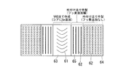
- the burner for forming the core part sprays glass particles on the target obliquely from below and deposits the glass particles on the target. Therefore, as shown in FIG. 6B, the arcuate striation 61 tends to remain in the core portion 63 manufactured by the VAD method.
- the external attachment method is a method of manufacturing a porous silica material by depositing glass fine particles (soot fine particles) in multiple layers using a plurality of burners around a rotating optical fiber core rod.
- Each burner has a variation in the maximum temperature and temperature distribution on the surface on which the glass particles are deposited due to differences in dimensional error and deterioration during manufacture. Therefore, it is inevitable that a difference occurs in the bulk density of the glass fine particle layer (soot layer) deposited by each burner.
- the amount of fluorine addition depends on the surface area of the quartz porous body, that is, the bulk density. Therefore, when fluorine is added using an external method, unevenness in fluorine concentration occurs in the external layer because there is a difference in bulk density between each layer of the soot and within each layer. As a result, the size of the trench portion varies in the radial direction and longitudinal direction of the base material and between lots, and the bending loss of the manufactured optical fiber becomes unstable.
- optical fiber characteristics such as cut-off wavelength and bending loss characteristics of the manufactured optical fiber (hereinafter referred to as optical fiber characteristics). May cause fluctuations in yield, and cause a decrease in yield.
- Patent Document 2 when an additive (here, Ge) is added to a quartz porous body, the concentration distribution of the additive is likely to occur. Since striae appear as a result, the refractive index distribution cannot be measured accurately due to the existence of striae, and it is difficult to control the optical fiber characteristics.
- an additive here, Ge
- the concentration distribution of the additive is likely to occur. Since striae appear as a result, the refractive index distribution cannot be measured accurately due to the existence of striae, and it is difficult to control the optical fiber characteristics.
- the thickness of the soot per traverse is 20 ⁇ m or less in terms of the thickness after sintering.
- the bulk density of soot is not disclosed in Patent Document 2, for example, when the bulk density is 0.5 g / cm 3 with a base material of ⁇ 20 mm, the thickness of the soot after sintering is 20 ⁇ m. Is about 80 ⁇ m, which is very thin. In the production of such a thin soot, even if there is a difference in additive concentration due to the difference in bulk density in the soot layer, striae and the like are unlikely to occur.
- the present invention has been made in view of such circumstances, and is a method for producing a porous silica body and a method for producing an optical fiber preform that can uniformly and efficiently add fluorine into the soot layer.
- An object of the present invention is to provide a porous silica material and an optical fiber preform.
- a method for producing a porous silica material according to an aspect of the present invention includes a step of arranging a plurality of burners around an optical fiber core rod; and a plurality of burners on an outer peripheral surface of the optical fiber core rod.
- a porous porous body manufacturing method comprising: depositing a plurality of soot layers, wherein each of the plurality of soot layers is formed by one of the plurality of burners; and Each soot layer has an average bulk density x (g / cm 3 ) and a deposition thickness y (mm), 0.2 ⁇ x ⁇ 0.5 and 0.1 ⁇ y ⁇ 4.0x 2 Deposition is performed so that ⁇ 3.8x + 1.3 is satisfied, and the maximum bulk density of the plurality of soot layers is 0.6 g / cm 3 or less.
- each soot layer may be deposited so as to satisfy 0.2 ⁇ x ⁇ 0.5 and 0.1 ⁇ y ⁇ 0.4.
- the optical fiber core rod may be produced by a VAD method.
- An optical fiber preform manufacturing method includes an optical fiber obtained by dehydrating and sintering a quartz porous body manufactured by the above-described manufacturing method of a quartz porous body in a fluorine-based gas. Use as a base material.
- the quartz porous body according to one aspect of the present invention is a quartz porous body having a plurality of soot layers deposited on the outer peripheral surface of an optical fiber core rod, and the bulk density of the plurality of soot layers.
- the maximum value is 0.6 g / cm 3 or less, and each soot layer has an average bulk density x (g / cm 3 ) and a deposition thickness y (mm). ⁇ 0.5 and 0.1 ⁇ y ⁇ 4.0x 2 ⁇ 3.8x + 1.3.
- each soot layer may satisfy 0.2 ⁇ x ⁇ 0.5 and 0.1 ⁇ y ⁇ 0.4.
- the optical fiber preform according to an aspect of the present invention is the above-described (a quartz porous body is dehydrated and sintered in a fluorine-based gas.
- the method for producing a porous silica body the method for producing an optical fiber preform, the quartz porous body, and the optical fiber preform, it is possible to uniformly and efficiently add fluorine into the soot layer. .
- FIG. 1 It is a figure which shows an example of the refractive index distribution of the optical fiber obtained from the optical fiber preform manufactured by the manufacturing method of the optical fiber preform concerning one embodiment of the present invention, and its sectional view. It is the schematic of the apparatus which attaches a soot layer to the outer peripheral surface of the core rod for optical fibers. It is a figure which shows the process of attaching a some soot layer externally with a some burner. It is a figure explaining the method of calculating the unevenness
- FIG. 1 is a cross-sectional view of an optical fiber 17 and a diagram showing an embodiment of its refractive index distribution.
- the optical fiber 17 shown in FIG. 1 is manufactured by heating an optical fiber preform manufactured by an optical fiber preform manufacturing method, which will be described later, and thinning (drawing) it to a thickness of about 125 ⁇ m.
- the optical fiber preform has almost the same refractive index distribution structure as the optical fiber 17 with respect to the ratio. By heating and stretching the optical fiber preform, an optical fiber 17 is produced in which the refractive index distribution structure of the optical fiber preform is almost inherited.
- the radius a 2 of the outer edge On the outer periphery of the core 1, the radius a 2 of the outer edge, the first cladding layer 2 of the maximum refractive index n 2 is provided.
- the maximum refractive index when the radius of the outer edge of a layer a n, the radius of the outer edge of one inner layer of the layer was set to a n-1, between a n-1, a n
- the largest refractive index at (the largest refractive index in one layer).
- the maximum refractive index defined by the above method is used.
- a maximum refractive index n 1 of the core 1, the maximum of the first maximum refractive index n 2 of the cladding layer 2, the second cladding layer 3 of the maximum refractive index n 3, and a third cladding layer 4 greater is designed than any of the refractive index n 4.
- the maximum refractive index n 3 of the second cladding layer 3 are all are designed to be smaller than the first cladding layer 2 of the maximum refractive index n 2 and a maximum refractive index n 4 of the third cladding layer 4.
- the refractive index distribution of the optical fiber is formed by adding a dopant such as germanium or fluorine.
- a dopant such as germanium or fluorine.
- the boundary between layers may be ambiguous in the refractive index distribution due to the influence of dopant diffusion or the like.
- the refractive index in the first cladding layer 2 is substantially constant in the radial direction, and the refractive index distribution of the entire optical fiber 17 has a substantially complete step shape.
- the refractive index profile of the optical fiber according to the present invention does not necessarily have a complete step shape.
- the diameter of each layer is defined by the following method.
- the radius a 1 of the core 1 is defined as the distance from the position where the relative refractive index difference decreases to 1/10 of the maximum relative refractive index difference ⁇ 1 in the core 1 to the fiber center.
- the outer edge radius a 3 of the first radius a 2 of the outer edge of the cladding layer 2, and a second cladding layer 3 is the differential value of the size distribution of the respective relative refractive index difference ⁇ (r) d ⁇ (r) / It is defined as a distance from a position where dr (r represents a radius) takes an extreme value to the fiber center.
- the relative refractive index difference ⁇ i (unit:%) of each layer of the optical fiber 17 is based on the maximum refractive index n 4 of the third cladding layer 4 and is represented by the following formula (1).
- n i is the maximum refractive index of each layer
- FIG. 2 is a schematic view of an external device for externally attaching glass fine particles serving as a cladding material around an optical fiber core rod including a core portion serving as a core of an optical fiber.
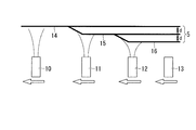
- FIG. 3 is a schematic view showing a process in which glass fine particle layers (soot layers) are externally attached in layers by a plurality of burners 10, 11, 12, and 13.
- the optical fiber core rod 6 is composed of a core portion that becomes the core 1 of the optical fiber 17 and a first cladding portion that becomes the first cladding layer 2 of the optical fiber 17.
- the optical fiber core rod 6 is manufactured by the VAD method.
- gas used as a raw material for an optical fiber is sent to a burner together with oxygen and hydrogen, and a raw material gas is sprayed onto the quartz rod together with an oxyhydrogen flame from below the rotating quartz rod to deposit glass particles.
- a rod-shaped core preform is produced by heating to transparent vitrification.
- Both ends in the longitudinal direction of the optical fiber core rod 6 are rotatably supported by the support member 7.
- a plurality of burners 8 are disposed around the optical fiber core rod 6, and the optical fiber core rod 6 and the plurality of burners 8 are traversed (relatively moved) in the longitudinal direction of the optical fiber core rod 6 (direction parallel to the rotation axis). It is possible.
- a gas serving as a glass raw material is fed into the burner 8 together with oxygen and hydrogen, and glass fine particles generated in the burner flame are sprayed onto the outer peripheral surface of the optical fiber core rod 6 to produce a porous silica body 5.
- both ends of the optical fiber core rod 6 are directly supported by the support member 7, but dummy rods (not shown) are flame welded to the both ends of the optical fiber core rod 6 as necessary.
- the dummy rod may be rotatably supported by the support member 7.
- one glass fine particle layer (soot layer) is externally attached to each burner during one traverse, and the glass fine particle layer (soot layer) deposited in layers. Is formed.
- the thickness of the glass particles deposited on the optical fiber core rod 6 (the outer diameter of the quartz porous body 5) is measured by a displacement measuring device using a laser light source 9. In this displacement measuring device, the distance between the laser light source 9 and the quartz porous body 5 is measured by a displacement sensor (not shown). In the external device shown in FIG.
- the external conditions such as the flow rate of the source gas and the flow rate of the oxyhydrogen flame are set so that the thickness and bulk density of the soot layer externally attached per burner are uniform in all the soot layers. Is controlling. Information on the external amount per traverse measured by the displacement measuring instrument during one external process is stored in a storage device (not shown) together with the burner external conditions used in the external process. Information regarding the burner external condition and the external amount stored in the storage device is reflected in the burner external condition in the next external process.
- the glass particles deposited on the optical fiber core rod 6 are dehydrated and sintered in a sintering furnace. Then, by repeating the above-described glass fine particle deposition treatment and glass fine particle sintering treatment, the second clad portion that becomes the second clad layer 3 of the optical fiber 17 on the outer peripheral surface of the optical fiber core rod 6; A third cladding portion that becomes the third cladding layer 4 of the optical fiber 17 is sequentially formed. At this time, when sintering a plurality of soot layers to be the second cladding part, the sintering is performed so that the refractive index of the second cladding part is smaller than the refractive indexes of the first cladding part and the third cladding part.
- a fluorine-based gas such as CF 4 , SiF 4 , SF 6 is introduced into the sintering furnace, and fluorine is added to the second cladding part.
- fluorine-based gas such as CF 4 , SiF 4 , SF 6 is introduced into the sintering furnace, and fluorine is added to the second cladding part.
- a plurality of burners 10, 11, 12, and 13 are arranged at approximately equal intervals along the longitudinal direction of the optical fiber core rod 6.
- four burners 10, 11, 12, and 13 are shown, but the number of burners is not limited to this.
- One of the burners 10, 11, 12, 13 and the optical fiber core rod 6 is fixed, and the other moves to the left or right (one direction along the longitudinal direction of the optical fiber core rod 6). The position changes.
- SiCl 4 (silicon tetrachloride) is used as a source gas sent into the plurality of burners 10, 11, 12, and 13. SiCl 4 fed into the burners 10, 11, 12 and 13 together with oxygen and hydrogen becomes glass fine particles in the flame of the burners 10, 11, 12 and 13. The glass particles are deposited on the outer peripheral surface of the rotating optical fiber core rod 6. Then, while rotating the optical fiber core rod 6, the plurality of burners 10, 11, 12, 13 are traversed in the longitudinal direction (rotational axis direction) of the optical fiber core rod 6, thereby A plurality of glass fine particle layers (soot layers) 14, 15, and 16 are deposited.
- glass fine particle layers (soot layers) 14, 15, 16 that are externally attached by each burner for each traverse are laminated one by one.
- One soot layer is produced by traversing one burner in one direction along the longitudinal direction of the optical fiber core rod 6.
- n soot layers are produced. Therefore, in FIG. 3, a quartz porous body having a large number of soot layers on the outer peripheral surface of the optical fiber core rod can be produced by traversing the plurality of burners 10, 11, 12, 13 a plurality of times.
- the bulk density of the soot (glass fine particles) and the thickness of the soot layer deposited by one burner in the external attachment process It is important to control the length d within a certain range.
- the first point is the bulk density of soot.
- the bulk density of the region produced by the external method is increased at the initial stage of deposition on the optical fiber core rod 6 and is made to be lower toward the outer peripheral portion, thereby reducing strain associated with shrinkage during vitrification. The effect is obtained.
- the bulk density of each soot layer and the average bulk density of each soot layer must be within a predetermined range.
- the bulk density of each soot layer is defined as the bulk density of one soot layer deposited by each burner during one traverse.
- the porous silica material is composed of four burners (from the inner layer side of the porous quartz material 5, glass particles are deposited in the order of burner 10 ⁇ burner 11 ⁇ burner 12 ⁇ burner 13 ⁇ burner 10. 5 is produced, the thickness of one soot layer produced by the burner 11 is calculated using the outer diameters of the burner 10 and the burner 11 and the accumulated weight of the glass fine particles. Alternatively, for convenience, the thickness and deposition weight of the soot layer may be calculated for every two burners, and the thickness divided by 2 may be used as the thickness and weight of one soot layer.
- the outer diameter of the porous quartz body after the two soot layers are deposited by the burners 10 and 11, and the burners 10, 11, 12, 13 is used to measure the outer diameter of the quartz porous body after depositing the four soot layers. From the data, the thickness of the two soot layers deposited by the burner 12 and the burner 13 is obtained. A value obtained by dividing the thickness of the two soot layers by 2 may be the respective thicknesses of the soot layers produced by the burner 12 and the burner 13.
- the average bulk density refers to the outer diameter of the final quartz porous body and the starting core material (core rod for optical fiber.
- the quartz porous body is formed on the outer peripheral surface of the core rod for optical fiber and sintered to form a base.
- the thickness of all deposited soot layers is obtained from the outer diameter of the base material formed by the latest sintering process.
- the density obtained from the thickness of the soot layer, the deposited weight, and the length of the base material is defined as the bulk density.
- the distance between the laser light source and the quartz porous body is measured with a displacement sensor (for example, LK-2000 manufactured by Keyence), and the outer diameter of the quartz porous body is continuously obtained to determine whether each soot layer is obtained.
- the bulk density and the average bulk density of all the soot layers are calculated.
- the bulk density of the quartz porous body (soot layer) can be adjusted by adjusting the flow rate of the raw material gas, the flow rate of the oxyhydrogen flame, and increasing the diameter of the starting core material.
- the bulk density is reduced by lowering the flow rate of hydrogen gas and lowering the surface temperature when glass particles are deposited.
- the maximum value of the bulk density of each soot layer of the quartz porous body is 0.6 g / cm 3 or less, and the average bulk density is suitably within the range of 0.2 g / cm 3 or more and 0.5 g / cm 3 or less depending on the thickness of the soot layer. It is good to set.
- the bulk density of the soot layer is preferably 0.2 to 0.6 g / cm 3 .
- the average bulk density x (g / cm 3 ) when it exceeds 0.5 g / cm 3 , the diffusion of fluorine is slow, and the production efficiency is lowered, for example, the traverse speed of the quartz porous material passing through the heater is slow.
- the lower limit of the average bulk density is not particularly limited. However, if the average bulk density is smaller than 0.2 g / cm 3 , the quartz porous body 5 is easily broken during transportation or the like, or the outer diameter of the quartz porous body 5 becomes thick and large. Therefore, it is preferable that the actual operation is 0.2 to 0.5 g / cm 3 (0.2 ⁇ x ⁇ 0.5).
- the thickness y (mm) of one soot layer produced by one burner as the second point is 0 in the range where the average bulk density x (g / cm 3 ) is 0.2 ⁇ x ⁇ 0.5. Desirably, the range is 1 ⁇ y ⁇ 4.0x 2 ⁇ 3.8x + 1.3. In particular, when the average bulk density x (g / cm 3 ) is in the range of 0.2 ⁇ x ⁇ 0.5, the thickness y (mm) of one soot layer is in the range of 0.1 ⁇ y ⁇ 0.4. In some cases, the soot layer can be deposited efficiently.
- the thickness of one soot layer is made thinner than 0.1 mm, the deposition efficiency of the glass fine particles is poor and the cost is likely to increase. Further, if the thickness of one soot layer is 0.1 mm or more, the baking by the heat of the burner flame when the soot layer that is overlaid on the soot layer is relaxed, so that a plurality of soot layers are deposited. An increase in bulk density can be avoided.
- the degree of unevenness in the refractive index distribution of the optical fiber preform is defined by the following formula (2).
- the range used for the moving average may be appropriately selected depending on the measurement step, the number of data, and the shape of the refractive index distribution.
- the moving average of the relative refractive index difference ⁇ is taken in the range of the base material diameter of X ⁇ 0.1 mm.
- “ ⁇ at X” in the above formula (2) indicates a relative refractive index difference ⁇ with respect to the core portion at the position X.
- the measurement interval at the time of measuring the refractive index distribution is 20 ⁇ m in this embodiment.
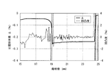
- FIG. 4A shows the range used for calculating the degree of unevenness.
- 5A and 5B show an example of the refractive index distribution in an actual optical fiber.
- FIGS. 4A and 4B are views showing the optical fiber preform 25 and its refractive index distribution according to the present embodiment.
- the optical fiber preform 25 of FIGS. 4A and 4B has substantially the same refractive index distribution structure with respect to the refractive index distribution and ratio of the optical fiber 17 shown in FIG. That is, a core portion 21 having a radius a 21 and a maximum refractive index n 21 , which becomes the core 1 of the optical fiber 17, is provided at the center of the optical fiber preform 25.
- a first cladding layer 2 of the optical fiber 17, the radius a 22 of the outer edge, the first cladding portion 22 of the maximum refractive index n 22 is provided.
- the size of the maximum refractive index n 21 of the core portion 21 of the optical fiber preform 25 is substantially the same as the size of the maximum refractive index n 1 of the core 1 of the optical fiber 17.
- the maximum refractive index n 22 of the first cladding portion 22 of the optical fiber preform 25 is substantially the same as the maximum refractive index n 2 of the first cladding layer 2 of the optical fiber 17.
- the size of the maximum refractive index n 23 of the second cladding portion 23 of the optical fiber preform 25 is substantially the same as the size of the maximum refractive index n 3 of the second cladding layer 3 of the optical fiber 17.
- the size of the maximum refractive index n 24 of the third cladding portion 24 of the optical fiber preform 25 is substantially the same as the size of the maximum refractive index n 4 of the third cladding layer 4 of the optical fiber 17. Further, the ratio of the sizes of the core portion 21 and the clad portions 22, 23, 24 (a 21 : a 22 : a 23 : a 24 ) is the same as the core 1 of the optical fiber 17 and the clad layers 2, 3, 4. It is the same as the size ratio (a 1 : a 2 : a 3 : a 4 ).
- the constituent elements of the optical fiber preform 25 (core portion 21, first cladding portion 22, second cladding portion 23, third cladding portion 24) and the constituent elements of optical fiber 17 (core 1, first cladding layer 2,
- the maximum refractive indexes of the second cladding layer 3 and the third cladding layer 4) are “substantially the same” when the influence of the spinning tension when the optical fiber preform 25 is spun is ignored. Means that.
- the maximum refractive index n 23 of the second cladding part 23 is smaller than any of the maximum refractive index n 24 of the maximum refractive index n 22 and the third cladding portion 24 of the first cladding portion 22.
- the method of defining the diameters of the core part 21, the first cladding part 22, the second cladding part 23, and the third cladding part 24 is as follows: the core 1 of the optical fiber 17, the first cladding layer 2, the second cladding layer 3, This is the same as the method for defining the diameters of the three cladding layers 4. That is, the radius a 21 of the core portion 21 is the distance from the position where the relative refractive index difference decreases to 1/10 of the maximum relative refractive index difference ⁇ 21 in the core portion 21 to the base material center (fiber center).
- the outer edge of the radius a 23 of the first outer edge of the radius a 22 of the cladding portion 22, and a second cladding portion 23 is a differential value of the size distribution of the respective relative refractive index difference ⁇ (r) d ⁇ (r) / It is defined as the distance from the position where dr (r represents the radius) takes an extreme value to the center of the base material (fiber center).
- the relative refractive index differences n 21 , n 22 , n 23 , and n 24 of the core portion 21, the first cladding portion 22, the second cladding portion 23, and the third cladding portion 24 have a reference refractive index of 3 except that the maximum refractive index n 24 of the cladding portion 24, the core 1 of the optical fiber 17 described with reference to equation (1), first cladding layer 2, the second cladding layer 3, and the third cladding layer 4 This is the same as the method for calculating the relative refractive index difference.
- the second cladding part (trench part) which is a fluorine-added region of the optical fiber preform (in the case of an optical fiber manufactured by a conventional manufacturing method)
- the rate distribution graph shows jagged lines. In this case, the unevenness variation is ⁇ 2% or more.
- the striae of the second cladding part is small as shown in FIG. 5A (in the case of an optical fiber manufactured by the manufacturing method of the present invention)
- a smooth curve appears in the refractive index distribution graph, and the degree of unevenness also varies. As small as ⁇ 0.5%.
- the traverse speed of the burner and the rotation speed of the main shaft of the optical fiber core rod 6 can be adjusted. As far as the inventors have studied, it has been confirmed that increasing the burner traverse speed is more effective.
- the thickness y (mm) of one soot layer produced with one burner is 0.1
- the occurrence of striae can be suppressed.
- the thickness y (mm) of one soot layer is in the range of 0.1 ⁇ y ⁇ 0.4.
- the soot layer can be deposited efficiently. Further, when the above conditions are satisfied, it is not necessary to consider the shrinkage of the bulk density even when the soot layers are stacked and deposited.
- Example 1 glass microparticles using eight multi-nozzle type quartz burners on a core rod (average core relative refractive index difference ⁇ 1 : 0.35%) of ⁇ 42 ⁇ 1200 mm manufactured by the VAD method.
- the gas flow rates were SiCl 4 flow rate: 2-5 SLM, oxygen flow rate: 18-35 SLM, hydrogen flow rate: 25-45 SLM, and Ar gas for sealing: 1 SLM.
- the main shaft rotation speed of the target optical fiber core rod was 25 rpm, and the traverse speed of each burner was 220 mm / min.
- the surface temperature of the quartz porous body being externally attached was measured using a thermotracer (TH3104MR manufactured by NEC Sanei), it was 1050 ° C. when the innermost layer was deposited and 880 ° C. when the outermost layer was externally attached.
- the bulk density was continuously measured by the following method. The distance between the laser light source and the surface of the quartz porous body was measured using a laser, and the thickness of the soot layer deposited from the distance was calculated. In this example, the thickness of the porous quartz body was obtained every time the deposition layer (corresponding to two layers) was produced with two burners, and the value obtained by dividing the obtained thickness by 2 was produced with one burner. It was set as the thickness of each soot layer. The bulk density for each layer was calculated from the thickness of the soot layer, the deposition weight, and the deposition distance.
- This quartz porous preform was set in a quartz muffle and sintered in a mixed gas of He and SiF 4 to obtain an optical fiber preform having a diameter of 50 mm.
- the SiF 4 concentration in the quartz muffle was 1.5%, and SiF 4 gas was used until the sintering was completed.
- the relative refractive index difference ⁇ 3 in both the radial direction and the longitudinal direction of the optical fiber preform was ⁇ 0.24. It was stable in the range of -0.26%. Further, when the unevenness degree of the second cladding part (trench part) was calculated using the refractive index data, the fluctuation was ⁇ 0.5%, which was good. Thereafter, the third clad portion was produced by an external attachment method to obtain a final optical fiber preform.
- optical fiber preforms according to Examples 2 to 18 and Comparative Examples 1 to 9 were produced in the same manner as in Example 1.
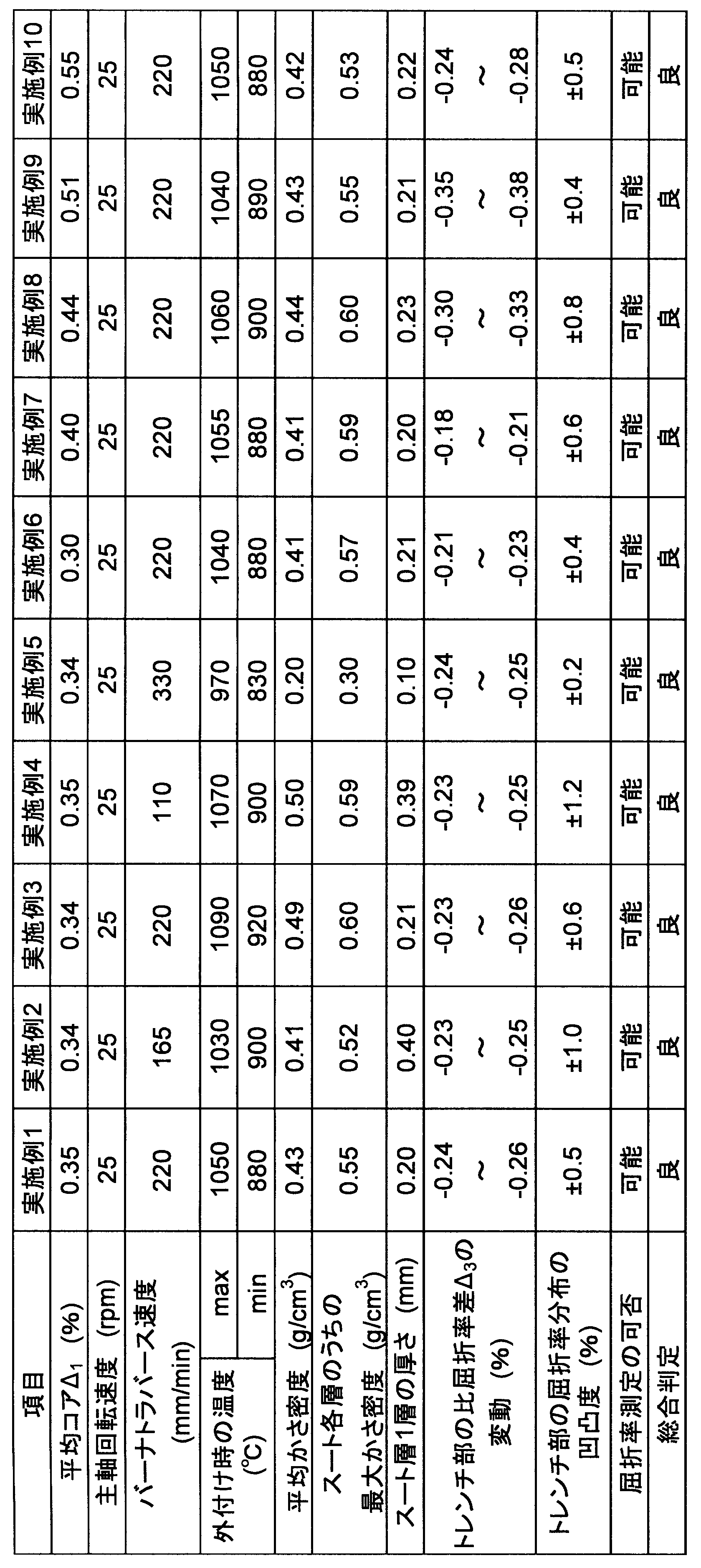
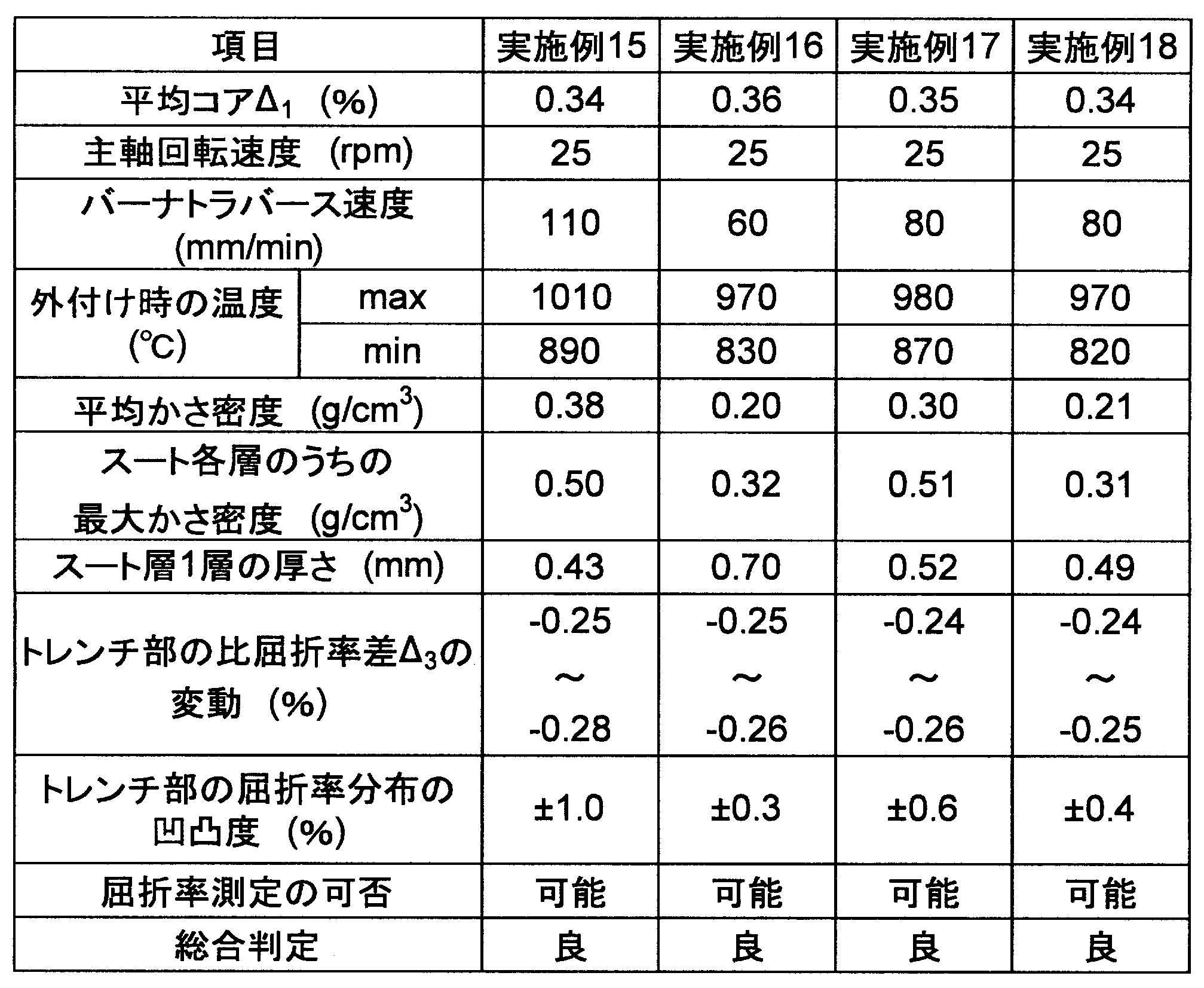
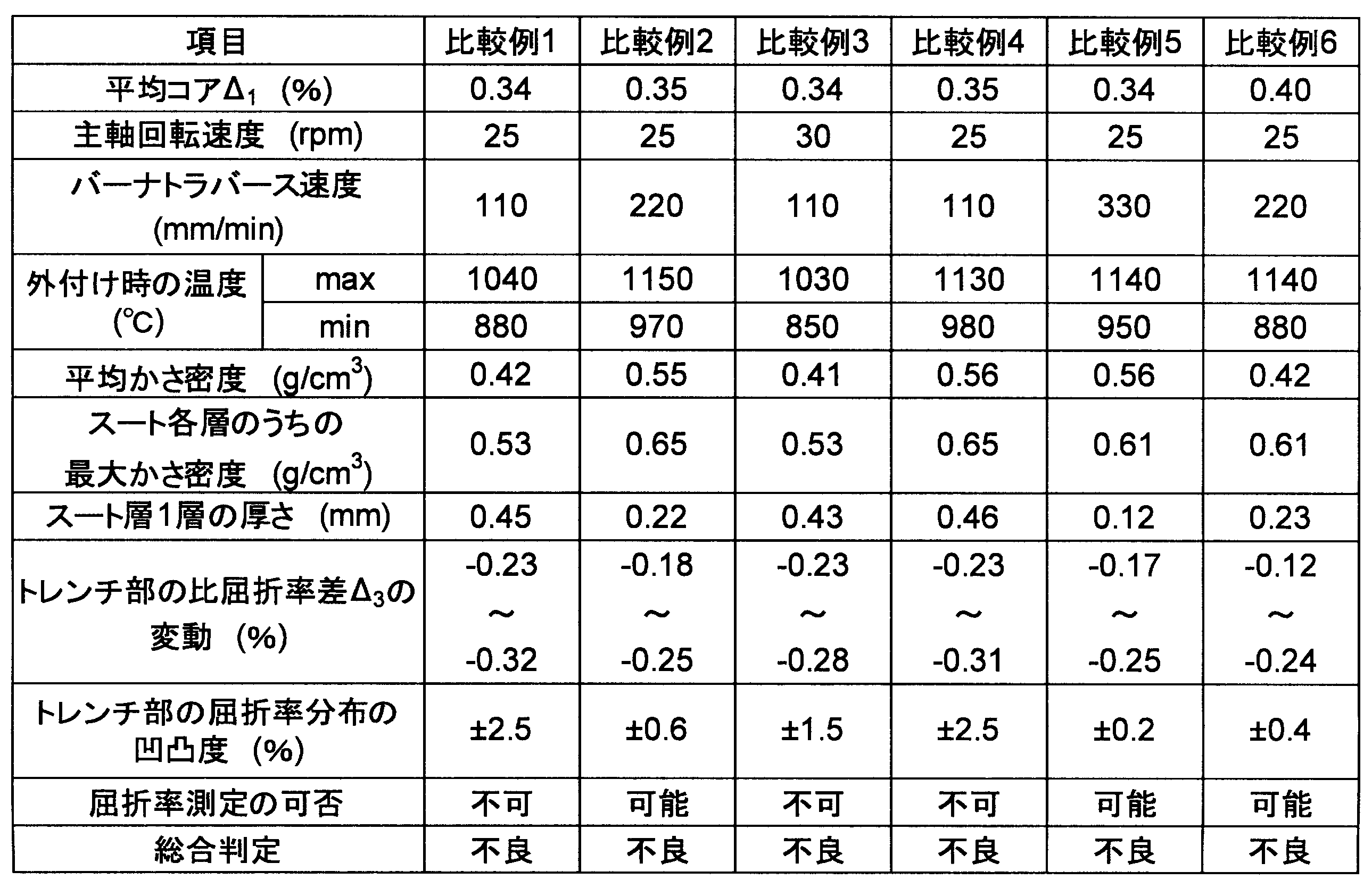
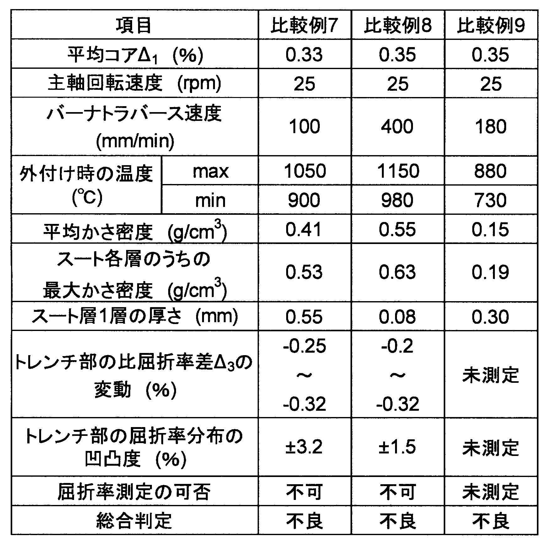
- the production conditions for each example and comparative example are summarized in Tables 1 to 4.
- the production conditions of the optical fiber preforms according to Examples 2 to 18 and Comparative Examples 1 to 9 are the same as those of Example 1 except those shown in Tables 1 to 4.
- Example 3 since the thickness of one soot layer was as thin as 0.21 to 0.22 mm, no influence of striae was observed, and the refractive index could be measured in both cases.
- the average bulk density of the second cladding part is 0.49 g / cm 3 , and the variation in the relative refractive index difference of the second cladding part is small in both the radial direction and the longitudinal direction of the optical fiber preform, and good characteristics are obtained. Showed stability.
- Comparative Example 2 since the average bulk density when the second cladding portion was externally attached was as large as 0.55 g / cm 3 , fluorine could not be diffused to the vicinity of the center of the optical fiber preform. For this reason, the relative refractive index difference of the second cladding portion was ⁇ 0.18% on the inner peripheral side of the second cladding portion and ⁇ 0.25% on the outer peripheral side, and uneven fluorine addition occurred in the radial direction.
- Comparative Example 3 the average bulk density was almost the same as that of Comparative Example 1 by increasing the spindle rotation speed, but the thickness of one soot layer could be reduced to 0.43 mm. .
- the unevenness of the second cladding part was ⁇ 1.5%, and the refractive index distribution could not be measured accurately. From this, it was found that the unevenness of ⁇ 1.5% is insufficient for stabilizing the characteristics.
- Example 4 From the result of Example 4, if the thickness of one soot layer is 0.39 mm, the influence of the striae of the second cladding portion is small (unevenness of ⁇ 1.2%), and an accurate refractive index distribution is measured. I was able to. Further, since the average bulk density was as low as 0.5 g / cm 3 , the variation in the relative refractive index difference of the second cladding portion in both the radial direction and the longitudinal direction of the optical fiber preform was small, and good characteristic stability was exhibited.
- Example 5 From the results of Example 5, it was confirmed that even if the average bulk density was lowered to 0.2 g / cm 3 , it could be produced without soot cracking. Further, by reducing the thickness of one soot layer to 0.1 mm, the striae level was almost not recognized (unevenness degree: ⁇ 0.2%). As a result, the relative refractive index difference of the second cladding part was ⁇ 0.24% on the inner peripheral side of the second cladding part and ⁇ 0.25% on the outer peripheral side, and the addition of fluorine could be made uniform.
- Comparative Example 6 is under the same conditions as in Example 1 except that the surface temperature of the quartz porous body at the start of external attachment is high and the maximum bulk density is increased.
- fluorine was not added in the region inside the second cladding part. It is considered that the increase in bulk density made it difficult for the fluorine-based gas to diffuse into the quartz porous body, and the reaction did not proceed.
- the amount of fluctuation of the relative refractive index difference delta 3 of the second cladding part is increased, the characteristic variation occurs.
- Example 11 the burner traverse speed was the same as that in Example 2 but was 165 mm / min, but the average bulk density was lowered because the surface temperature of the quartz porous body at the time of external attachment was low. Changes in average of the second cladding part by the bulk density is low relative refractive index difference delta 3 it was smaller. Further, the unevenness degree of the refractive index of the second cladding part was as low as ⁇ 0.3%, and the refractive index measurement was possible without any problem, which was good.
- Example 12 the burner traverse speed was 300 mm / min faster than Examples 6 to 10, and the thickness of one soot layer was reduced. For this reason, the unevenness degree of the refractive index of the second cladding part was also as low as ⁇ 0.4%, which was a favorable result.
- Example 13 the burner traverse speed is the same as in Examples 6 to 10, but the surface temperature of the quartz porous body at the time of external attachment is low. As a result, the average bulk density decreased. As a result, the relative refractive index difference delta 3 variation of the second cladding part is reduced, and also irregularity of the refractive index of the second cladding part was low and good.
- Example 14 the burner traverse speed was 180 mm / min slower than Examples 6 to 10, and the thickness of one soot layer was increased. However, the average bulk density was as low as 0.35 g / cm 3 . Therefore, the relative refractive index difference delta 3 variation of the second cladding part, and irregularity of the refractive index of the second cladding part becomes comparable, it was good.
- Example 15 the burner traverse speed was the same as in Comparative Examples 1 and 3, but the thickness of one soot layer was 0.4 mm or more. However, since the temperature at the time of external attachment was lowered, the average bulk density was reduced to 0.38 g / cm 3 . As a result, the unevenness degree of the refractive index of the second cladding part was suppressed to ⁇ 1.0%. Therefore, the refractive index could be measured without any problem and was good. From this, it was found that even if the thickness of one soot layer is 0.4 mm or more, the average bulk density may be 0.4 g / cm 3 or less.
- the soot thickness was increased to 0.49 to 0.70 mm by lowering the burner traverse speed. Further, the average bulk density could be lowered to 0.20 to 0.30 g / cm 3 by adjusting the temperature at the time of external attachment low. As a result, variations in the relative refractive index difference delta 3 of the second cladding part is small, irregularity of the refractive index of the second cladding part can also be reduced, good results were obtained.
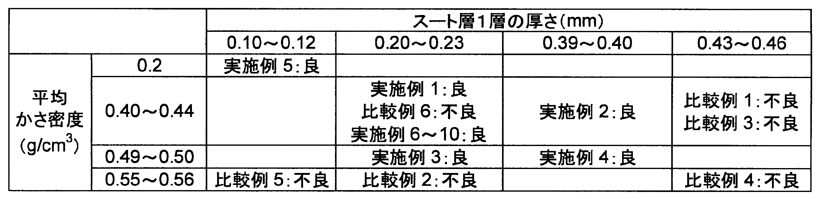
- Example 6 The results of Examples 1 to 10 and Comparative Examples 1 to 6 are summarized in Table 6. The results of all the examples and comparative examples are summarized as shown in FIG. According to Table 6 and FIG. 7, the average value of the bulk density (the average bulk density that is the average of the bulk densities of all the soot layers included in the quartz porous body) x (g / cm 3 ) is 0.2 ⁇ In the range of x ⁇ 0.5, the average deposition thickness y (mm) of the plurality of soot layers is in the range of 0.1 ⁇ y ⁇ 4.0x 2 ⁇ 3.8x + 1.3 (indicated by a broken line in FIG. 7). It is understood that it is effective to obtain good results.
- the average value of the bulk density the average bulk density that is the average of the bulk densities of all the soot layers included in the quartz porous body
- x g / cm 3
- the average deposition thickness y (mm) of the plurality of soot layers is in the range of
- the thickness y (mm) of one soot layer is in the range of 0.1 ⁇ y ⁇ 0.4.
- the soot layer can be deposited efficiently.
- the maximum value of the bulk density in each soot layer is larger than 0.6 g / cm 3 , the variation in the relative refractive index difference of the second cladding portion becomes large (Comparative Example 6). ), And the maximum value of the bulk density needs to be 0.6 g / cm 3 or less.
- the soot layer is uniformly and efficiently provided. Fluorine addition can be performed. Therefore, if an optical fiber is produced by drawing such an optical fiber base material, an optical fiber as shown in FIG. 1 having little loss due to bending and excellent connectivity with a general transmission optical fiber can be obtained. It can be provided at low cost.
- an optical fiber that can uniformly and efficiently add fluorine to the inside of the soot layer, has little loss due to bending, and has excellent connectivity with a general transmission optical fiber.
Landscapes
- Chemical & Material Sciences (AREA)
- Engineering & Computer Science (AREA)
- Geochemistry & Mineralogy (AREA)
- Life Sciences & Earth Sciences (AREA)
- General Chemical & Material Sciences (AREA)
- General Life Sciences & Earth Sciences (AREA)
- Chemical Kinetics & Catalysis (AREA)
- Manufacturing & Machinery (AREA)
- Materials Engineering (AREA)
- Organic Chemistry (AREA)
- Physics & Mathematics (AREA)
- Thermal Sciences (AREA)
- Manufacture, Treatment Of Glass Fibers (AREA)
Abstract
Description
本願は、2010年3月3日に、日本国に出願された特願2010-046780号に基づき優先権を主張し、その内容をここに援用する。
(1)本発明の一態様に係る石英多孔質体の製造方法は、光ファイバ用コアロッドの周囲に複数のバーナを配置する工程と;前記複数のバーナによって前記光ファイバ用コアロッドの外周面上に複数のスート層を堆積させる堆積工程と;を備える石英多孔質体の製造方法であって、前記堆積工程では、前記複数のスート層それぞれを、前記複数のバーナの1によって形成して且つ、前記各スート層を、平均かさ密度をx(g/cm3)、堆積厚さをy(mm)としたときに、0.2≦x≦0.5及び0.1≦y≦4.0x2-3.8x+1.3を満たし、前記複数のスート層のかさ密度の最大値は0.6g/cm3以下となるように堆積する。
(2)上記石英多孔質体の製造方法において、前記各スート層を、0.2≦x≦0.5及び0.1≦y≦0.4を満たすように堆積してもよい。
(6)上記石英多孔質体において、前記各スート層が、0.2≦x≦0.5及び0.1≦y≦0.4を満たしてもよい。
図1は、光ファイバ17の断面図と、その屈折率分布の一実施形態を示す図である。図1の光ファイバ17は、後述する光ファイバ母材の製造方法によって製造された光ファイバ母材を加熱して125μm程度の太さにまで細く引き延ばす(線引きする)ことによって作製される。光ファイバ母材は光ファイバ17と比率に関してほぼ同じ屈折率分布構造を持っている。光ファイバ母材を加熱して引き延ばすことで、光ファイバ母材の屈折率分布構造をほぼそのまま引き継いだ光ファイバ17が作製される。

次に、図2~図5Bを用いて、図1の光ファイバ17を製造するための光ファイバ母材の製造方法を説明する。図2は、光ファイバのコアとなるコア部を含む光ファイバ用コアロッドの周囲に、クラッド材料となるガラス微粒子を外付けする外付け装置の概略図である。また、図3は、複数のバーナ10,11,12,13によってガラス微粒子の層(スート層)が1層ずつ層状に外付けされる工程を示す模式図である。
スート層1層の厚さが4.0x2-3.8x+1.3(mm)より厚い場合、スート層1層内でのかさ密度の差が大きくなりやすく、フッ素の添加量にむらが発生してしまう。結果として屈折率分布測定器(プリフォームアナライザ)で脈理が観測され、正確な屈折率分布の測定ができずにファイバ特性を安定化することが難しくなる。
また、スート層1層の厚みが0.1mm以上であれば、その上に重なるスート層を作製する際のバーナ火炎の熱での焼締めが緩和されるため、複数のスート層を堆積する間にかさ密度が上昇することを避けることができる。

外付け中はかさ密度の測定を以下の方法で連続的に行った。レーザを用いて、レーザ光源と石英多孔質体の表面との距離を測定し、そこから堆積したスート層の厚みを算出した。本実施例ではバーナ2本分での堆積層(2層分に相当)作製毎に石英多孔質体の厚みを求め、求められた厚みを2で除した値を、バーナ1本で作製された各スート層の厚みとした。スート層の厚み、堆積重量、及び堆積距離から1層毎のかさ密度を算出した。

2 第1クラッド層
3 第2クラッド層
4 第3クラッド層
5 石英多孔質体
6 光ファイバ用コアロッド
8,10,11,12,13 バーナ
14,15,16 スート層(バーナ1本あたりで堆積されるガラス微粒子の層)
17 光ファイバ
21 コア部
22 第1クラッド部
23 第2クラッド部
24 第3クラッド部
25 光ファイバ母材
61,62 脈理
Claims (7)
- 光ファイバ用コアロッドの周囲に複数のバーナを配置する工程と;
前記複数のバーナによって前記光ファイバ用コアロッドの外周面上に複数のスート層を堆積させる堆積工程と;
を備える石英多孔質体の製造方法であって、
前記堆積工程では、前記複数のスート層それぞれを、前記複数のバーナの1によって形成して且つ、前記各スート層を、平均かさ密度をx(g/cm3)、堆積厚さをy(mm)としたときに、0.2≦x≦0.5及び0.1≦y≦4.0x2-3.8x+1.3を満たし、前記複数のスート層のかさ密度の最大値が0.6g/cm3以下となるように堆積することを特徴とする石英多孔質体の製造方法。 - 前記各スート層を、0.2≦x≦0.5及び0.1≦y≦0.4を満たすように堆積する
ことを特徴とする請求項1に記載の石英多孔質体の製造方法。 - 前記光ファイバ用コアロッドをVAD法により作製する
ことを特徴とする請求項1に記載の石英多孔質体の製造方法。 - 請求項1又は3に記載の製造方法により製造された石英多孔質体をフッ素系ガス中で脱水及び焼結する
ことを特徴とする光ファイバ母材の製造方法。 - 光ファイバ用コアロッドの外周面上に堆積させた複数のスート層を有する石英多孔質体であって、
前記複数のスート層のかさ密度の最大値が0.6g/cm3以下であり、
前記各スート層は、平均かさ密度をx(g/cm3)、堆積厚さをy(mm)としたときに、0.2≦x≦0.5及び0.1≦y≦4.0x2-3.8x+1.3を満たす
ことを特徴とする石英多孔質体。 - 前記各スート層が、0.2≦x≦0.5及び0.1≦y≦0.4を満たす
ことを特徴とする請求項5に記載の石英多孔質体。 - 請求項5に記載の石英多孔質体がフッ素系ガス中で脱水及び焼結されてなる
ことを特徴とする光ファイバ母材。
Priority Applications (3)
| Application Number | Priority Date | Filing Date | Title |
|---|---|---|---|
| CN201180007916.4A CN102741183B (zh) | 2010-03-03 | 2011-03-03 | 石英多孔质体的制造方法、光纤母材的制造方法、石英多孔质体及光纤母材 |
| JP2012503242A JP5695025B2 (ja) | 2010-03-03 | 2011-03-03 | 光ファイバ母材の製造方法 |
| US13/596,816 US20120321891A1 (en) | 2010-03-03 | 2012-08-28 | Manufacturing method of porous silica body, manufacturing method of optical fiber preform, porous silica body, and optical fiber preform |
Applications Claiming Priority (2)
| Application Number | Priority Date | Filing Date | Title |
|---|---|---|---|
| JP2010046780 | 2010-03-03 | ||
| JP2010-046780 | 2010-03-03 |
Related Child Applications (1)
| Application Number | Title | Priority Date | Filing Date |
|---|---|---|---|
| US13/596,816 Continuation US20120321891A1 (en) | 2010-03-03 | 2012-08-28 | Manufacturing method of porous silica body, manufacturing method of optical fiber preform, porous silica body, and optical fiber preform |
Publications (1)
| Publication Number | Publication Date |
|---|---|
| WO2011108639A1 true WO2011108639A1 (ja) | 2011-09-09 |
Family
ID=44542286
Family Applications (1)
| Application Number | Title | Priority Date | Filing Date |
|---|---|---|---|
| PCT/JP2011/054901 Ceased WO2011108639A1 (ja) | 2010-03-03 | 2011-03-03 | 石英多孔質体の製造方法、光ファイバ母材の製造方法、石英多孔質体、及び光ファイバ母材 |
Country Status (4)
| Country | Link |
|---|---|
| US (1) | US20120321891A1 (ja) |
| JP (1) | JP5695025B2 (ja) |
| CN (1) | CN102741183B (ja) |
| WO (1) | WO2011108639A1 (ja) |
Cited By (6)
| Publication number | Priority date | Publication date | Assignee | Title |
|---|---|---|---|---|
| JP2013088818A (ja) * | 2011-10-17 | 2013-05-13 | Sehf-Korea Co Ltd | 曲げ損失強化光ファイバ |
| US20140060118A1 (en) * | 2011-11-30 | 2014-03-06 | Steven Bruce Dawes | Pressed, multilayered silica soot preforms for the manufacture of single sinter step, complex refractive index profile optical fiber |
| KR20150062115A (ko) * | 2013-11-28 | 2015-06-05 | 신에쓰 가가꾸 고교 가부시끼가이샤 | 광섬유용 실리카 유리 모재의 제조 방법 |
| JP2017043512A (ja) * | 2015-08-26 | 2017-03-02 | 株式会社フジクラ | 光ファイバ母材の製造方法、光ファイバの製造方法およびレンズの製造方法 |
| WO2019069989A1 (ja) * | 2017-10-06 | 2019-04-11 | 住友電気工業株式会社 | 光ファイバ用プリフォーム、光ファイバ用プリフォームの製造方法、及び、光ファイバ用プリフォームの脈理ピッチの設定方法 |
| JP2023015689A (ja) * | 2021-07-20 | 2023-02-01 | 株式会社フジクラ | 光ファイバ母材の製造方法 |
Families Citing this family (12)
| Publication number | Priority date | Publication date | Assignee | Title |
|---|---|---|---|---|
| JP5520640B2 (ja) * | 2010-03-08 | 2014-06-11 | 株式会社フジクラ | 母材の着脱方法及び光ファイバの製造方法 |
| JP5342614B2 (ja) * | 2011-08-09 | 2013-11-13 | 古河電気工業株式会社 | 光ファイバ母材および光ファイバの製造方法 |
| EP2938581B1 (en) | 2012-12-28 | 2018-05-02 | Prysmian S.p.A. | Method of manufacturing preforms for optical fibres having low water peak |
| US9975802B2 (en) * | 2013-05-31 | 2018-05-22 | Corning Incorporated | Method for making low bend loss optical fiber preforms |
| JP6310378B2 (ja) * | 2013-11-28 | 2018-04-11 | 信越化学工業株式会社 | 光ファイバ用シリカガラス母材の製造方法 |
| CN104926099A (zh) * | 2015-05-26 | 2015-09-23 | 江苏高科物流科技股份有限公司 | 一种高纯玻璃的生产方法 |
| DK3359498T3 (da) * | 2015-10-09 | 2021-02-22 | Prysmian Spa | Fremgangsmåde til fremstilling af en glaskernepræform til optiske fibre |
| JP2018016533A (ja) * | 2016-07-29 | 2018-02-01 | 信越化学工業株式会社 | 光ファイバ用ガラス母材の製造方法 |
| WO2018098816A1 (zh) * | 2016-12-02 | 2018-06-07 | 中天科技精密材料有限公司 | 光纤预制棒的制造设备、制造方法及其制造系统 |
| JP6694915B2 (ja) * | 2018-06-12 | 2020-05-20 | 株式会社フジクラ | 多孔質ガラス微粒子体の製造方法および光ファイバ母材の製造方法 |
| CN113248133B (zh) * | 2021-05-31 | 2021-09-17 | 中天科技精密材料有限公司 | 光纤预制棒制造设备及应用其的光纤预制棒的制作方法 |
| CN114907007B (zh) * | 2022-06-15 | 2024-02-02 | 山东富通光导科技有限公司 | 一种光纤预制棒松散体中掺氟的方法 |
Citations (5)
| Publication number | Priority date | Publication date | Assignee | Title |
|---|---|---|---|---|
| JPS62191434A (ja) * | 1986-02-17 | 1987-08-21 | Sumitomo Electric Ind Ltd | 光フアイバ用ガラス母材の製造方法 |
| JPS6374931A (ja) * | 1986-09-16 | 1988-04-05 | Sumitomo Electric Ind Ltd | 単一モ−ド光フアイバ用母材の製造方法 |
| JPH11157865A (ja) * | 1997-11-21 | 1999-06-15 | Furukawa Electric Co Ltd:The | 大型光ファイバ母材の製造方法 |
| JP2000272930A (ja) * | 1999-03-26 | 2000-10-03 | Mitsubishi Cable Ind Ltd | 光ファイバ母材の製造方法 |
| JP2003020241A (ja) * | 2001-07-02 | 2003-01-24 | Furukawa Electric Co Ltd:The | モードフィールド変換用光ファイバの製造方法 |
Family Cites Families (9)
| Publication number | Priority date | Publication date | Assignee | Title |
|---|---|---|---|---|
| US4292063A (en) * | 1980-05-05 | 1981-09-29 | Northern Telecom Limited | Manufacture of an optical fiber preform with micro-wave plasma activated deposition in a tube |
| CN1015539B (zh) * | 1984-03-01 | 1992-02-19 | 住友电气工业株式会社 | 光导纤维玻璃预制件的制造方法 |
| JPS60260430A (ja) * | 1984-06-04 | 1985-12-23 | Sumitomo Electric Ind Ltd | フツ素をクラツド部に含有する光フアイバ用母材の製造方法 |
| CN1012362B (zh) * | 1985-04-01 | 1991-04-17 | 住友电气工业株式会社 | 单模光纤玻璃预制棒的制造方法 |
| US20020073740A1 (en) * | 2000-12-20 | 2002-06-20 | Dawes Steven B. | Fluorine doping a soot preform |
| DE10152328B4 (de) * | 2001-10-26 | 2004-09-30 | Heraeus Tenevo Ag | Verfahren zur Herstellung eines Rohres aus Quarzglas, rohrförmiges Halbzeug aus porösem Quarzglas u. Verwendung desselben |
| JP2003171136A (ja) * | 2001-11-30 | 2003-06-17 | Fujikura Ltd | 光ファイバ用多孔質材およびその製造方法、光ファイバ母材およびその製造方法 |
| US7209626B2 (en) * | 2003-01-27 | 2007-04-24 | Peter Dragic | Waveguide configuration |
| US7921675B2 (en) * | 2007-11-16 | 2011-04-12 | Corning Incorporated | Methods for making optical fiber preforms and microstructured optical fibers |
-
2011
- 2011-03-03 WO PCT/JP2011/054901 patent/WO2011108639A1/ja not_active Ceased
- 2011-03-03 CN CN201180007916.4A patent/CN102741183B/zh active Active
- 2011-03-03 JP JP2012503242A patent/JP5695025B2/ja active Active
-
2012
- 2012-08-28 US US13/596,816 patent/US20120321891A1/en not_active Abandoned
Patent Citations (5)
| Publication number | Priority date | Publication date | Assignee | Title |
|---|---|---|---|---|
| JPS62191434A (ja) * | 1986-02-17 | 1987-08-21 | Sumitomo Electric Ind Ltd | 光フアイバ用ガラス母材の製造方法 |
| JPS6374931A (ja) * | 1986-09-16 | 1988-04-05 | Sumitomo Electric Ind Ltd | 単一モ−ド光フアイバ用母材の製造方法 |
| JPH11157865A (ja) * | 1997-11-21 | 1999-06-15 | Furukawa Electric Co Ltd:The | 大型光ファイバ母材の製造方法 |
| JP2000272930A (ja) * | 1999-03-26 | 2000-10-03 | Mitsubishi Cable Ind Ltd | 光ファイバ母材の製造方法 |
| JP2003020241A (ja) * | 2001-07-02 | 2003-01-24 | Furukawa Electric Co Ltd:The | モードフィールド変換用光ファイバの製造方法 |
Cited By (11)
| Publication number | Priority date | Publication date | Assignee | Title |
|---|---|---|---|---|
| JP2013088818A (ja) * | 2011-10-17 | 2013-05-13 | Sehf-Korea Co Ltd | 曲げ損失強化光ファイバ |
| US8787719B2 (en) | 2011-10-17 | 2014-07-22 | Samsung Electronics Co., Ltd. | Bend insensitive fiber |
| US20140060118A1 (en) * | 2011-11-30 | 2014-03-06 | Steven Bruce Dawes | Pressed, multilayered silica soot preforms for the manufacture of single sinter step, complex refractive index profile optical fiber |
| US9108876B2 (en) * | 2011-11-30 | 2015-08-18 | Corning Incorporated | Pressed, multilayered silica soot preforms for the manufacture of single sinter step, complex refractive index profile optical fiber |
| KR20150062115A (ko) * | 2013-11-28 | 2015-06-05 | 신에쓰 가가꾸 고교 가부시끼가이샤 | 광섬유용 실리카 유리 모재의 제조 방법 |
| KR102217526B1 (ko) * | 2013-11-28 | 2021-02-18 | 신에쓰 가가꾸 고교 가부시끼가이샤 | 광섬유용 실리카 유리 모재의 제조 방법 |
| JP2017043512A (ja) * | 2015-08-26 | 2017-03-02 | 株式会社フジクラ | 光ファイバ母材の製造方法、光ファイバの製造方法およびレンズの製造方法 |
| WO2019069989A1 (ja) * | 2017-10-06 | 2019-04-11 | 住友電気工業株式会社 | 光ファイバ用プリフォーム、光ファイバ用プリフォームの製造方法、及び、光ファイバ用プリフォームの脈理ピッチの設定方法 |
| US11378737B2 (en) | 2017-10-06 | 2022-07-05 | Sumitomo Electric Industries, Ltd. | Optical fiber preform, method for manufacturing optical fiber preform, and method for setting striae pitch of optical fiber preform |
| JP2023015689A (ja) * | 2021-07-20 | 2023-02-01 | 株式会社フジクラ | 光ファイバ母材の製造方法 |
| JP7722858B2 (ja) | 2021-07-20 | 2025-08-13 | 株式会社フジクラ | 光ファイバ母材の製造方法 |
Also Published As
| Publication number | Publication date |
|---|---|
| US20120321891A1 (en) | 2012-12-20 |
| JPWO2011108639A1 (ja) | 2013-06-27 |
| CN102741183A (zh) | 2012-10-17 |
| JP5695025B2 (ja) | 2015-04-01 |
| CN102741183B (zh) | 2016-02-03 |
Similar Documents
| Publication | Publication Date | Title |
|---|---|---|
| JP5695025B2 (ja) | 光ファイバ母材の製造方法 | |
| EP2755066B1 (en) | Optical fiber, optical fiber preform and method of fabricating same | |
| JP5636151B2 (ja) | 多波長、多モード光ファイバ | |
| JP5799903B2 (ja) | シングルモード光ファイバ | |
| US9382149B2 (en) | Methods for producing a semifinished part for the manufacture of an optical fiber which is optimized in terms of bending | |
| JP6513796B2 (ja) | 一工程フッ素トレンチ及びオーバークラッドを有する光ファイバプリフォームの作製方法 | |
| US11001520B2 (en) | Optical fiber glass preform manufacturing method | |
| CN111615499B (zh) | 光纤母材的制造方法、光纤母材以及光纤的制造方法、光纤 | |
| JP6079114B2 (ja) | マルチモード光ファイバ | |
| JP7455079B2 (ja) | 光ファイバ | |
| JP5744070B2 (ja) | 光ファイバを製造するための方法並びに管状半製品 | |
| JP2013056787A (ja) | 光ファイバ母材の製造方法 | |
| JP2012171802A (ja) | 光ファイバ母材の製造方法 | |
| JP2013056786A (ja) | 光ファイバ用母材の製造方法 | |
| CN102276145A (zh) | 一种光波导轴向均匀的光纤预制棒制作方法 | |
| CN101097273A (zh) | 宏弯曲不敏感光学纤维 | |
| CN105334568A (zh) | 一种低损耗大有效面积单模光纤及其光纤预制棒制造方法 | |
| CN104834053A (zh) | 多模光纤及其制造方法 | |
| US20250298182A1 (en) | Preform for multicore optical fibers | |
| JP6431349B2 (ja) | 光ファイバ母材の製造方法 | |
| WO2023219116A1 (ja) | 光ファイバ母材及び光ファイバ母材の製造方法 | |
| EP4579292B1 (en) | Single mode optical fiber | |
| JP2014201475A (ja) | 光ファイバ母材の製造方法及び製造装置 | |
| JP5000333B2 (ja) | 光ファイバ用石英ガラス多孔質体の製造方法 | |
| JP3953855B2 (ja) | 多孔質母材の製造方法 |
Legal Events
| Date | Code | Title | Description |
|---|---|---|---|
| WWE | Wipo information: entry into national phase |
Ref document number: 201180007916.4 Country of ref document: CN |
|
| 121 | Ep: the epo has been informed by wipo that ep was designated in this application |
Ref document number: 11750748 Country of ref document: EP Kind code of ref document: A1 |
|
| WWE | Wipo information: entry into national phase |
Ref document number: 2012503242 Country of ref document: JP |
|
| WWE | Wipo information: entry into national phase |
Ref document number: 7557/CHENP/2012 Country of ref document: IN |
|
| NENP | Non-entry into the national phase |
Ref country code: DE |
|
| 122 | Ep: pct application non-entry in european phase |
Ref document number: 11750748 Country of ref document: EP Kind code of ref document: A1 |