WO2011108627A1 - 光源装置 - Google Patents
光源装置 Download PDFInfo
- Publication number
- WO2011108627A1 WO2011108627A1 PCT/JP2011/054865 JP2011054865W WO2011108627A1 WO 2011108627 A1 WO2011108627 A1 WO 2011108627A1 JP 2011054865 W JP2011054865 W JP 2011054865W WO 2011108627 A1 WO2011108627 A1 WO 2011108627A1
- Authority
- WO
- WIPO (PCT)
- Prior art keywords
- light
- reflecting mirror
- source device
- light source
- mercury lamp
- Prior art date
- Legal status (The legal status is an assumption and is not a legal conclusion. Google has not performed a legal analysis and makes no representation as to the accuracy of the status listed.)
- Ceased
Links
Images





Classifications
-
- G—PHYSICS
- G03—PHOTOGRAPHY; CINEMATOGRAPHY; ANALOGOUS TECHNIQUES USING WAVES OTHER THAN OPTICAL WAVES; ELECTROGRAPHY; HOLOGRAPHY
- G03B—APPARATUS OR ARRANGEMENTS FOR TAKING PHOTOGRAPHS OR FOR PROJECTING OR VIEWING THEM; APPARATUS OR ARRANGEMENTS EMPLOYING ANALOGOUS TECHNIQUES USING WAVES OTHER THAN OPTICAL WAVES; ACCESSORIES THEREFOR
- G03B21/00—Projectors or projection-type viewers; Accessories therefor
- G03B21/14—Details
- G03B21/20—Lamp housings
- G03B21/2006—Lamp housings characterised by the light source
- G03B21/2026—Gas discharge type light sources, e.g. arcs
-
- G—PHYSICS
- G03—PHOTOGRAPHY; CINEMATOGRAPHY; ANALOGOUS TECHNIQUES USING WAVES OTHER THAN OPTICAL WAVES; ELECTROGRAPHY; HOLOGRAPHY
- G03B—APPARATUS OR ARRANGEMENTS FOR TAKING PHOTOGRAPHS OR FOR PROJECTING OR VIEWING THEM; APPARATUS OR ARRANGEMENTS EMPLOYING ANALOGOUS TECHNIQUES USING WAVES OTHER THAN OPTICAL WAVES; ACCESSORIES THEREFOR
- G03B21/00—Projectors or projection-type viewers; Accessories therefor
- G03B21/14—Details
- G03B21/20—Lamp housings
- G03B21/2046—Positional adjustment of light sources
-
- G—PHYSICS
- G03—PHOTOGRAPHY; CINEMATOGRAPHY; ANALOGOUS TECHNIQUES USING WAVES OTHER THAN OPTICAL WAVES; ELECTROGRAPHY; HOLOGRAPHY
- G03B—APPARATUS OR ARRANGEMENTS FOR TAKING PHOTOGRAPHS OR FOR PROJECTING OR VIEWING THEM; APPARATUS OR ARRANGEMENTS EMPLOYING ANALOGOUS TECHNIQUES USING WAVES OTHER THAN OPTICAL WAVES; ACCESSORIES THEREFOR
- G03B21/00—Projectors or projection-type viewers; Accessories therefor
- G03B21/14—Details
- G03B21/20—Lamp housings
- G03B21/2066—Reflectors in illumination beam
-
- H—ELECTRICITY
- H01—ELECTRIC ELEMENTS
- H01J—ELECTRIC DISCHARGE TUBES OR DISCHARGE LAMPS
- H01J61/00—Gas-discharge or vapour-discharge lamps
- H01J61/84—Lamps with discharge constricted by high pressure
- H01J61/86—Lamps with discharge constricted by high pressure with discharge additionally constricted by close spacing of electrodes, e.g. for optical projection
Definitions
- This invention relates to a light source device.
- the present invention relates to a light source device used in a projector device.
- a projector apparatus using a liquid crystal (LCD) panel and a DLP (registered trademark) system there are 1 and 3 types of LCD panel systems.
- the radiated light from the light source is separated into three colors (RGB), and the LCD panel supports image information.
- RGB three colors
- the transmitted light is adjusted for transmission, and then the three colors transmitted through the panel are combined and projected onto the screen.
- a method using a DLP is a method in which a spatial modulation element (also referred to as a light modulation device, specifically a DMD element, etc.) is passed through a rotary filter in which RGB light is divided and formed from light emitted from a light source.
- Irradiation is performed in a time-sharing manner, and specific light is reflected by the DMD element to irradiate the screen.
- a DMD element is made up of millions of small mirrors corresponding to each pixel, and the projection of light is controlled by controlling the direction of each small mirror.
- the DLP system has a merit that the entire apparatus is small and simple because the optical system is simple and there is no need to use three LCD panels.
- a short arc type mercury lamp having a high vapor pressure is used as a light source of the projector apparatus.
- a lamp with a high mercury vapor pressure can obtain light in the visible wavelength region with high output.
- This short arc type mercury lamp is incorporated in a concave ellipsoidal reflecting mirror in order to brighten the image projected on the screen. This is because, by using the concave reflecting mirror, the light emitted from the short arc type mercury lamp in all directions can be focused and efficiently radiated on the screen having a limited area.
- FIG. 9 shows a schematic structure of a conventionally proposed light source device.
- This light source device is disclosed in Japanese Patent Application Laid-Open No. 11-64795.
- a main reflecting mirror 20 and a sub reflecting mirror 30 are provided separately from the main reflecting mirror 20, and the short arc type mercury lamp 10 to the main reflecting mirror 20 are provided.
- the short arc type mercury lamp 10 to the main reflecting mirror 20 are provided.
- the electrodes of the light emitting section 11 and returned to the main reflecting mirror 20 again. 51 is used.
- a technique including a lens 42 having a function of correcting an optical path of light emitted from a reflecting mirror is shown.
- the problem to be solved by the present invention is to provide a light source device that can efficiently use the radiated light of a short arc type mercury lamp and is suitable for the demand for miniaturization.
- a light source device of the present invention includes a short arc type mercury lamp including a light emitting portion having a pair of electrodes and sealing portions provided at both ends of the light emitting portion, The main reflection made of a spheroid surface arranged so as to surround the short arc type mercury lamp with the arc direction of the short arc type mercury lamp being coincident with the optical axis and the first focal point being substantially formed between the electrodes.
- the secondary reflector is disposed so as to surround the opening of the main reflecting mirror, and is adapted to reflect again the light directly emitted from the short arc type mercury lamp toward the opening of the main reflecting mirror toward the main reflecting mirror.
- a reflector An opening for passing the light reflected from the main reflecting mirror formed in the sub-reflecting mirror;
- a light source device comprising: The main reflecting mirror reflects ultraviolet light and visible light among radiated light of the short arc type mercury lamp, but transmits infrared light.
- the sub-reflecting mirror reflects ultraviolet light and visible light among the radiated light of the short arc mercury lamp,
- a wavelength-selective optical member that transmits visible light but reflects ultraviolet light out of the reflected light from the main reflecting mirror is disposed at a position between the second focal position of the main reflecting mirror and the sub-reflecting mirror. It is characterized by.
- the light source device is further characterized in that the sub-reflecting mirror transmits infrared light out of the radiated light of the short arc mercury lamp.
- the above light source device is further characterized in that the sub-reflecting mirror is made of an aluminum material.
- the wavelength-selective optical member may be configured such that an incident surface thereof is perpendicularly incident with light from the main reflecting mirror, and transmits visible light to the incident surface to transmit ultraviolet light. It has the film
- the above light source device is further characterized in that the wavelength selective optical member has a flat incident surface, and has a film that transmits visible light and reflects ultraviolet light on the incident surface.
- the above light source device is further characterized in that the sub-reflecting mirror is constituted by a spherical reflecting mirror.
- the opening diameter of the main reflecting mirror and the opening diameter of the incident side of the sub-reflecting mirror are substantially the same.
- the above light source device is further characterized in that the opening diameter of the incident side of the sub-reflecting mirror is larger than the opening diameter of the main reflecting mirror.
- the opening on the incident side of the sub-reflecting mirror is continuous with the opening of the main reflecting mirror, and the electrode is arranged in a cross section cut along a plane including the optical axis of the main reflecting mirror.
- the above light source device is further characterized in that the short arc type mercury lamp has a protrusion formed at the tip of the electrode.
- a projector according to the present invention includes the light source device described above.
- the present invention has the following effects. (1) Of the light emitted from the short arc type mercury lamp, the ultraviolet light is returned to the light emitting part of the short arc type mercury lamp, so that the light emission of the short arc type mercury lamp can be enhanced. This is because the ultraviolet light is absorbed by mercury vapor in the lamp, so that the light emitting part is maintained at a high temperature as a whole. (2) Visible light of light emitted from a short arc type mercury lamp causes a problem that when the electrode returns directly to the electrode, the electrode is locally heated and worn, but in the present invention, as in the case of ultraviolet light The effect of heating the mercury vapor in the arc is exhibited, and as a result, the effect of increasing the light emission of the short arc type mercury lamp is obtained.
- a part of the visible light returned to the short arc type mercury lamp is short arc type mercury. Since mercury vapor having a lower temperature than that in the arc portion, which is present near the container wall of the light emitting portion of the lamp and the inner wall of the light emitting portion, is heated, the effect of increasing the light emission of the short arc type mercury lamp can be obtained. .
- the light source device of the present invention includes a main reflecting mirror, a sub reflecting mirror disposed on the opening side of the main reflecting mirror, and a wavelength selective optical member disposed on the optical axis on the sub reflecting mirror side.
- the ultraviolet light is confined in a region surrounded by the wavelength selective optical member and the reflecting mirror, and the ultraviolet light is not emitted from the wavelength selective optical member to the outside.
- the main reflecting mirror reflects ultraviolet light and visible light but transmits infrared light out of the radiated light of the short arc type mercury lamp, and also reflects by the main reflecting mirror.
- a wavelength-selective optical member that transmits visible light but reflects ultraviolet light is disposed at a position between the second focal position of the main reflecting mirror and the sub-reflecting mirror. Yes.
- a specific configuration will be described with reference to the drawings.
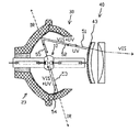
- FIG. 1 shows the overall configuration of an example of a light source device according to the present invention.
- the light source device includes a short arc type mercury lamp 10, a main reflecting mirror 20, and a sub-reflecting mirror 30.
- the main reflecting mirror 20 is arranged so as to surround the short arc type mercury lamp 10, and the arc direction of the short arc type mercury lamp 10, that is, the direction connecting the tips of the electrodes, and the optical axis Z of the main reflecting mirror 20.
- the main reflecting mirror 20 has a spheroidal surface structure having a first focal point at a substantially central position between the electrodes, and the sub-reflecting mirror 30 is formed in a spherical structure corresponding to the spherical shape of the lamp light emitting part. Yes.
- the short arc type mercury lamp 10 has a substantially spherical light emitting portion 11 and sealing portions 12a and 12b at both ends thereof, and one sealing portion 12a is attached to the neck (top) 24 of the main reflecting mirror 20.
- a heat-resistant adhesive 25 or the like may be used, and both may be directly attached as shown, or a base (not shown) which is a separate member (reflector).
- the base may be used to attach the short arc type mercury lamp 10 to the base, and the base may be fixed to the main reflecting mirror 20, and the base may be provided with a hole through which cooling air passes.
- the reflecting portion 22 of the main reflecting mirror 20 is a spheroidal surface and has a concave shape as a whole.
- the main reflecting mirror 20 has a base material 21 made of borosilicate glass, which is heat resistant glass, and has an interference film that reflects visible light (VIS) and ultraviolet light (UV) on its inner surface and transmits infrared light (IR). Formed and configured.
- the interference film is a film in which titania (TiO 2 ) and silica (SiO 2 ) are alternately laminated as a first layer on a base material, and a hafnia (second layer) is formed thereon.
- a film in which HfO 2 ) and magnesium fluoride (MgF) are alternately stacked is formed. Accordingly, for example, ultraviolet light having a wavelength of 300 nm to 400 nm can be reflected on the first layer, and visible light having a wavelength of 400 nm to 700 nm can be reflected on the second layer.
- the sub-reflecting mirror 30 is attached to the main reflecting mirror 20 by a dedicated metal fitting such as a heat-resistant silicone adhesive or stainless steel in a state where the incident side opening is continuous with the opening of the main reflecting mirror 20.
- the inner surface of the sub-reflecting mirror 30 has a substantially spherical shape following the light emitting portion 11 of the short arc type mercury lamp, whereby the light rays incident on the reflecting surface are reflected in the same direction. Since the sub-reflecting mirror 30 is provided at a position where the distance from the light emitting unit 11 is large, the influence of the high temperature of the short arc type mercury lamp is small.
- An interference film 32 that reflects visible light (VIS) and ultraviolet light (UV) and transmits infrared light (IR) is formed on the inner surface of the sub-reflecting mirror 30.
- the interference film is a film in which tantala (Ta 2 O 5 ) and silica (SiO 2 ) are alternately laminated as a first layer on a base material, and a second layer is formed thereon.
- a film in which hafnia (HfO 2 ) and magnesium fluoride (MgF) are alternately stacked is formed.
- ultraviolet light having a wavelength of 300 nm to 400 nm can be reflected on the first layer, and visible light having a wavelength of 400 nm to 700 nm can be reflected on the second layer.
- the interference film is not limited to this, and other combinations can be selected.
- the opening diameter of the main reflecting mirror 20 and the opening diameter of the sub-reflecting mirror 30 are substantially the same. This is because the maximum outer diameter of the light source device can be minimized by making the aperture diameters of the main reflecting mirror 20 and the sub-reflecting mirror 30 substantially coincide.
- a wavelength selective optical member 40 is disposed in front of the main reflecting mirror 20.
- the wavelength selective optical member 40 in this example is composed of two lenses 41 and 42.
- the incident-side lens 41 has an incident surface that is at least a convex surface (a surface having a central portion protruding in the same direction as the main reflecting mirror 20 (to the left in the figure)), and the light emitted from the main reflecting mirror 20
- the curved surface is perpendicular to the incident surface.
- it is desirable to use a so-called meniscus lens which is a single lens or a cemented lens having a convex entrance surface and a concave exit surface.
- the exit side lens 42 constituting the wavelength selective optical member 40 controls and adjusts the traveling direction of light.
- the lenses 41 and 42 constituting the wavelength selective optical member 40 are attached to a lens holding member (not shown), and the lens holding member is also attached to an optical unit (not shown).
- the lenses 41 and 42 have a size (outer diameter) capable of receiving all the light from the main reflecting mirror 20, and are disposed at a position where all the light from the main reflecting mirror 20 can be received.
- the lens 41 is made of, for example, borosilicate glass (for example, TEMPAX; trademark), which is hard glass, and transmits light (VIS) to the surface (incident surface) on the side of the main reflector 20 and transmits ultraviolet light.
- An interference film 43 that reflects light (UV) is provided.
- the interference film 43 is formed of a film in which hafnia (HfO 2 ) and magnesium fluoride (MgF) are alternately stacked on a base material.
- hafnia HfO 2
- MgF magnesium fluoride
- An antireflection film AR coating (not shown) is applied to the surface (outgoing surface) of the lenses 41 and 42 opposite to the main reflecting mirror 20. This is to prevent the visible light transmitted through the lenses 41 and 42 from being reflected again.
- a liquid crystal panel and a DLP rotating color filter are arranged in front of the wavelength selective optical member 40 in the light traveling direction to constitute a projector.
- FIG. 2 is a diagram for explaining the progress of the emitted light of the short arc type mercury lamp.
- the emitted light of the short arc type mercury lamp 10 includes visible light (VIS), infrared light (IR), and ultraviolet light (UV).
- the wavelength range of visible light (VIS) is approximately 400 nm to 700 nm
- the wavelength range of infrared light (IR) is approximately 700 nm or more
- the wavelength range of ultraviolet light (UV) is approximately 400 nm or less.
- the light incident on the reflecting mirror and the lens is indicated by a solid line
- visible light (VIS) transmitted through the lens and emitted is indicated by a one-dot chain line
- infrared light (IR) is indicated by a dotted line.
- the light 53 that reaches the sub-reflecting mirror 30 reflects visible light (VIS) and ultraviolet light (UV) and transmits infrared light (IR) in the sub-reflecting mirror 30.
- the light 55 that has reached the main reflecting mirror 20 reflects visible light (VIS) and ultraviolet light (UV) in the main reflecting mirror 20 and transmits infrared light (IR).
- the light 55 includes direct light from the short arc type mercury lamp 10, but also includes light reflected by the sub-reflecting mirror 30.
- the light 51 that has reached the wavelength-selective optical member 40 transmits visible light (VIS) and reflects ultraviolet light (UV) in the wavelength-selective optical member 40.
- the reflected ultraviolet light (UV) is returned to the short arc mercury lamp 10 again via the main reflecting mirror 20.
- infrared light (IR) is also reflected by the interference film 43.
- UV Ultraviolet light
- both electrodes have substantially the same shape and are relatively small. Therefore, by setting the angle X to 90 ° (see FIG. 1), the distance between the electrodes at the condensing point is reduced. The apparent distance (apparent arc size) can be approximately halved, and a light source with a smaller bright spot can be obtained.
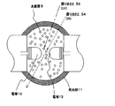
- FIG. 4 shows an enlarged state of the light emitting part 11 of the short arc type mercury lamp.
- the inside of the light emitting unit 11 is filled with mercury vapor.
- the mercury vapor absorbs ultraviolet light (UV) of the return lights 52 and 54 that return to the light emitting unit 11, thereby raising the temperature of the light emitting unit 11.
- UV ultraviolet light
- IR infrared light
- mercury vapor having a temperature lower than that of the arc portion, which exists near the inner wall of the light emitting portion of the short arc type mercury lamp.
- the temperature of the mercury vapor rises and the temperature of the tube wall of the container also rises. This enhances the light emission of the short arc type mercury lamp.
- the ultraviolet light is reflected again by the main reflecting mirror 20 and the sub-reflecting mirror 30 and returned to the light emitting part of the short arc type mercury lamp, and the short arc type mercury lamp emits light. Contribute to strengthening.
- the infrared light passes through the space between the electrodes, passes through the main reflecting mirror 20 without being reflected, and is emitted to the outside of the reflecting mirror.
- the infrared light that has passed through the space between the electrodes gradually becomes the first. Since the light travels in a different direction from the optical path and directly heats the electrodes, it is preferable that the infrared light once passed through the space between the electrodes pass through the main reflecting mirror and be emitted outside the reflecting mirror. .
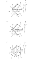
- the wavelength selective optical member 40 includes a lens 41 having an interference film 43 that reflects ultraviolet light and transmits visible light on an incident surface, and a lens 42 that controls an optical path.
- the wavelength selective optical member 40 in the example of (b) shows a configuration in which the interference film 43 is formed on the incident surface of the lens 41 having a function of controlling the optical path.
- the lens 42 in which the incident surface on which the interference film 44 having the same characteristics as the interference film 43 is formed is a flat surface and the opposite exit surface is a concave surface. It is constituted by.
- FIG. 6 is an explanatory sectional view showing another embodiment of the present invention.
- the sub-reflecting mirror 30 is based on aluminum. Things are used. Since it is the same as that of FIG. 1 except having changed the sub-reflection mirror 30 into the aluminum base material, description of the same member is abbreviate
- the sub-reflecting mirror 30 in this example is manufactured by aluminum spatula drawing, pressing, cutting, or the like, and has a rotary reflecting surface having the same shape as the example in FIG.
- the thickness of the base material of borosilicate glass becomes about 4 mm, whereas that of aluminum is as thin as about 1 mm and can be lightened, and there is no problem in strength. Even if the outer diameter is the same, the size of the opening of the sub-reflecting mirror that does not interfere with the emitted light can be increased, and the amount of light flux that can be captured can be increased.
- FIG. 7 shows the overall structure of the short arc type mercury lamp 10.
- the short arc type mercury lamp 10 is a discharge lamp in which mercury is enclosed, and has a substantially spherical light emitting portion 11 formed by a discharge vessel made of quartz glass.
- a light emitting space is formed in the light emitting portion 11, and the same electrodes 13a and 13b are arranged to face each other at an interval of 0.5 mm to 2 mm in the space.
- Sealing portions 12a and 12b are formed at both ends of the light emitting portion 11, and conductive metal foils 15a and 15b made of molybdenum are embedded in the sealing portions 12a and 12b, for example, in a hermetic manner by shrink seals. Has been.
- the shaft portions of the electrodes 13a and 13b are joined to the respective one ends of the metal foils 15a and 15b, and the external leads 14a and 14b are joined to the other ends of the metal foils 15a and 15b, respectively.
- Power is supplied from.
- the light emitting unit 11 is filled with mercury, rare gas, and halogen gas.
- Mercury is used to obtain a necessary ultraviolet light wavelength, for example, radiation having a wavelength of 300 nm to 360 nm, and is 0.15 mg / mm 3 or more, specifically 0.15 to 0.25 mg / mm 3 enclosed. Yes.
- the amount of sealing varies depending on the temperature condition, it becomes a high vapor pressure of 8 MPa or more during lighting.
- argon gas is sealed at a pressure of about 13 kPa. Its function is to improve the lighting startability.
- halogen iodine, bromine, chlorine and the like are enclosed in the form of mercury or other metals and compounds. The amount of enclosed halogen is selected from the range of 5 ⁇ 10 ⁇ 5 to 7 ⁇ 10 ⁇ 3 ⁇ mol / mm 3 .
- the function of the halogen is to extend the life using a so-called halogen cycle, but the extremely small and extremely high lighting vapor pressure such as the short arc type mercury lamp of the present invention also has the effect of preventing the devitrification of the discharge vessel. is there.
- An example of a numerical value of a short arc type mercury lamp is, for example, a maximum outer diameter of the light emitting part 11 of 9.5 mm, a distance between electrodes of 1.5 mm, an arc tube volume of 75 mm 3 , a rated voltage of 70 V, a rated power of 200 W, and an alternating current at 350 Hz. Illuminated.
- the tube wall load value of the short arc type mercury lamp is 0.8 to 2.0 W / mm 2 , specifically 1.5 W / mm 2 .
- a presentation device such as a projector device or an overhead projector
- light with good color rendering can be provided.
- the short arc type mercury lamp is not limited to AC lighting, and may be DC lighting.
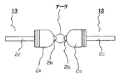
- FIG. 8 is a diagram schematically showing electrode tips and protrusions of a short arc type mercury lamp.
- a projection 2b is formed at the tip of the electrode 13 (the end facing the other electrode) as the short arc mercury lamp is turned on.
- the principle of the phenomenon in which the protrusion 2b is formed is not necessarily clear, but is estimated as follows. That is, tungsten (electrode constituent material) evaporated from the high-temperature portion near the electrode tip during lamp operation is combined with halogen and residual oxygen present in the arc tube, for example, when the halogen is Br, WBr, WBr 2 , WO, WO 2 , WO 2 Br, WO 2 Br 2 etc. exist as tungsten compounds.
- These compounds are decomposed into tungsten atoms or cations at a high temperature portion in the gas phase near the electrode tip.
- Temperature diffusion that is, diffusion of tungsten atoms from the arc that is the high temperature part in the gas phase to the vicinity of the tip of the electrode that is the low temperature part, and the tungsten atoms are ionized into cations in the arc, and the cathode It is considered that the drift of the electric field attracted toward the cathode by the electric field during operation increases the density of tungsten vapor in the gas phase in the vicinity of the electrode tip and precipitates at the electrode tip to form a protrusion.
- the electrode 13 includes a hemispherical portion 2a and a shaft portion 2c, and a protrusion 2b is formed at the tip of the hemispherical portion 2a.
- the protrusion 2b does not occur in any short arc type mercury lamp.
- the distance between the electrodes is 1 mm to 2 mm, and the light emitting part is filled with 0.08 mg / mm 3 or more of mercury, rare gas, and halogen in the range of 5 ⁇ 10 ⁇ 5 to 7 ⁇ 10 ⁇ 3 ⁇ mol / mm 3.
- the projection 2b is formed as the lamp is turned on, and an arc is formed between the projections 2b.
- the main reflecting mirror 20, the sub-reflecting mirror 30, and the wavelength selective optical member 40 are particularly limited to the above embodiments as long as they can reflect and transmit the radiated light from the short arc type mercury lamp. It is not something. However, it is preferable to use a member having excellent heat resistance and strength resistance from the viewpoint of use in the projector apparatus.
- the main reflecting mirror 20 is made of borosilicate glass, quartz glass or the like as a base material
- the sub-reflecting mirror 30 uses a metal material such as aluminum in addition to the members of the main reflecting mirror 20. Can do.
- the reason why the heat resistance is required is that the main reflecting mirror 20 becomes a high temperature of about 400 ° C. when the lamp is turned on.
- the reason why the strength resistance is required is that a short arc type mercury lamp should be used during the operation. This is because even if it is damaged, the reflecting mirror is not damaged, and it is possible to reliably prevent scattering of fragments of the short arc type mercury lamp.
- the wavelength selective optical member 40 is separated from the front opening of the sub-reflecting mirror 30.
- cooling air can be blown toward the sealing portion 12 b of the short arc type mercury lamp 10.
- the light source device of the present invention configured to reflect ultraviolet light with a wavelength of 380 nm to 400 nm with respect to the lens 41 of the main reflecting mirror 20, the sub-reflecting mirror 30, and the wavelength selective optical member 40, It was confirmed that the light output was improved by 7% compared to the conventional light source device that transmits ultraviolet light.
- the light source of the present invention is configured to reflect ultraviolet light having a wavelength of 300 nm to 400 nm with respect to the main reflecting mirror 20, the sub-reflecting mirror 30, and the lens 41 of the wavelength selective optical member 40. According to the device, it was confirmed that the light output was improved by 10% compared with the conventional light source device that transmits ultraviolet light.
- SYMBOLS 10 Short arc type mercury lamp 2a Hemisphere part 2b Protrusion 2c Shaft part 11 Light emission part 12a, 12b Sealing part 13, 13a, 13b Electrode 14a, 14b External lead 15a, 15b Conductive metal foil 20 Main reflecting mirror 21 Base material 22 Reflection Part 24 Neck part 25 Heat resistant adhesive 30 Subreflector 31 Substrate 32 Interference film 40 Wavelength selective optical member 41, 42 Lens 43, 44 Interference film 51, 53, 55 Light 52, 54 Return light
Landscapes
- Physics & Mathematics (AREA)
- General Physics & Mathematics (AREA)
- Non-Portable Lighting Devices Or Systems Thereof (AREA)
- Projection Apparatus (AREA)
Abstract
Description
LCDパネルを使う方式は、1枚式と3枚式があるが、いずれの方式であっても、光源からの放射光を3色(RGB)に分離して、LCDパネルにおいて画像情報に対応させた光を透過調整して、その後、パネルを透過した3色を合成させてスクリーン上に投射させる方式である。
一方、DLPを使う方式は、光源からの放射光をRGBの領域が分割形成された回転フィルターを介して、空間変調素子(光変調デバイスともいい、具体的にはDMD素子などをいう)などを時分割で照射し、このDMD素子で特定の光を反射させてスクリーンに照射するものである。DMD素子とは、1画素ごとに対応する小さな鏡を数百万個敷き詰めたものであって、一つ一つの小さな鏡の向きを制御することで光の投射が制御される。
DLP方式は、LCD方式に比較して、光学系が簡易であるとともに3枚ものLCDパネルを使う必要がないことから装置全体が小型簡易化するメリットがある。
また、このショートアーク型水銀ランプは、スクリーンに投射される画像を明るくするために、回転楕円面形状の凹面反射鏡の中に組み込まれる。凹面反射鏡を使うことで、ショートアーク型水銀ランプから四方八方に放射される光を集束させて、限られた面積のスクリーンに効率よく照射できるからである。
プロジェクター装置に対して小型化が要求されると、当然に、プロジェクター装置の中に組み込まれる、ショートアーク型水銀ランプおよび凹面反射鏡などによって構成される光源装置も小型化が要求される。
その一方で、当然ではあるが、このような寸法、形状の制約を受けたとしても、ショートアーク型水銀ランプの放射光の利用効率を低下させることはできない。
さらに、反射鏡より出射された光の光路修正機能を有するレンズ42により構成される技術が示されている。
このショートアーク型水銀ランプのアーク方向と光軸が一致するとともに、第一焦点が概ね前記電極間に形成された状態で当該ショートアーク型水銀ランプを取り囲むよう配置された回転楕円面からなる主反射鏡と、
該主反射鏡の開口部を取り囲むように配置されるとともに、該ショートアーク型水銀ランプから該主反射鏡の開口側へ直接放射された光を該主反射鏡に向けて再び反射させるための副反射鏡と、
前記副反射鏡に形成された、該主反射鏡から反射した光が通過するための開口部と、
よりなる光源装置において、
前記主反射鏡は、前記ショートアーク型水銀ランプの放射光のうち、紫外光と可視光を反射するが赤外光を透過するものであり、
前記副反射鏡は、前記ショートアーク型水銀ランプの放射光のうち、紫外光と可視光を反射するものであり、
該主反射鏡からの反射光のうち可視光を透過するが紫外光を反射する波長選択性光学部材が、該主反射鏡の第二焦点位置と該副反射鏡との間の位置に配置されていることを特徴とする。
上記の光源装置は、さらに、前記副反射鏡の入射側の開口径の大きさが、前記主反射鏡の開口径より大きいことを特徴とする。
(1)ショートアーク型水銀ランプから放射される光のうち紫外光がショートアーク型水銀ランプの発光部に戻されることにより、ショートアーク型水銀ランプの発光を高めることができる。これは、紫外光がランプ内の水銀蒸気に吸収されることにより、発光部が全体として高温に維持されるからである。
(2)ショートアーク型水銀ランプから放射される光のうち可視光は、直接電極に戻る場合は電極が局所的に高温化して損耗するという問題を生じるが、本発明では、紫外光と同様にアーク中の水銀蒸気を加熱する作用を発揮し、結果としてショートアーク型水銀ランプの発光を高める効果が得られ、さらに、ショートアーク型水銀ランプに戻った可視光の一部は、ショートアーク型水銀ランプの発光部の容器壁及び発光部の容器内壁付近に存在する、アーク部におけるよりも温度の低い水銀蒸気を加熱するので、これにより、当該ショートアーク型水銀ランプの発光を高める効果が得られる。
具体的構成を、図面を用いて説明する。
光源装置は、ショートアーク型水銀ランプ10、主反射鏡20、および副反射鏡30より構成される。主反射鏡20は、ショートアーク型水銀ランプ10を取り囲むように配置されており、ショートアーク型水銀ランプ10のアーク方向、すなわち、電極の先端同士を結ぶ方向と、主反射鏡20の光軸Zは一致している。また、主反射鏡20は、電極間のほぼ中心位置を、第一焦点とする回転楕円面構造であり、副反射鏡30はランプ発光部の球面形状に対応して球面状構造に形成されている。
そして、波長選択性光学部材40の光進行方向の前方に、液晶パネルやDLP用回転色フィルターが配置されてプロジェクターが構成される。
ショートアーク型水銀ランプ10の放射光には、可視光(VIS)、赤外光(IR)、紫外光(UV)が含まれている。可視光(VIS)の波長域は概ね400nm~700nmであり、赤外光(IR)の波長域は概ね700nm以上であり、紫外光(UV)の波長域は概ね400nm以下とした。図では、反射鏡やレンズに入射する光を実線で示し、レンズを透過し放射される可視光(VIS)を一点鎖線で示し、赤外光(IR)を点線で示している。
ランプ放射光のうち、副反射鏡30に達した光53は、副反射鏡30において、可視光(VIS)と紫外光(UV)を反射して、赤外光(IR)を透過させる。
次に、主反射鏡20に達した光55は、主反射鏡20において、可視光(VIS)と紫外光(UV)を反射して、赤外光(IR)を透過させる。光55は、ショートアーク型水銀ランプ10から直射する光もあるが、副反射鏡30で反射した光も含んでいる。
さらに、波長選択性光学部材40に達した光51は、この波長選択性光学部材40において、可視光(VIS)を透過して、紫外光(UV)を反射する。反射した紫外光(UV)は、主反射鏡20を介して、再びショートアーク型水銀ランプ10に戻される。なお、波長選択性光学部材40に達した光51のうち、赤外光(IR)も干渉膜43により反射される。
発光部11の内部には水銀蒸気が充満している。ここで、発光部11に戻ってくる戻り光52,54のうち紫外光(UV)を水銀蒸気が吸収することで、発光部11の温度が昇温する。一方、戻り光52,54に含まれる可能性のある赤外光(IR)は、ショートアーク型水銀ランプの発光部の容器内壁付近に存在する、アーク部よりも温度の低い水銀蒸気に吸収されて当該水銀蒸気の温度が上昇すると共に、容器の管壁の温度も上昇する。これによりショートアーク型水銀ランプの発光が強められる。
発光部11あるいは水銀蒸気に吸収されなかった紫外光と赤外光は、電極間の空間を通り抜け、ショートアーク型水銀ランプを通過する。このため、局所的に電極を高温化させることはなく、これによる電極損耗を避けることができる。電極の空間を通り抜けた戻り光52,54のうち紫外光は、再び主反射鏡20及び副反射鏡30に反射されてショートアーク型水銀ランプの発光部に戻され、ショートアーク型水銀ランプの発光を強めることに寄与する。一方、赤外光は電極間の空間を抜けた後、主反射鏡20に反射されることなく透過し、反射鏡外部へと放出される。紫外光と同様に、主反射鏡20と副反射鏡30の間を繰り返し反射させて発光部11に戻すことが有益とも思われるが、電極間の空間を抜けた赤外光は徐々に最初の光路と違う方向に進んでいき、電極を直接加熱してしまうことになるので、一度電極間の空間を通過した赤外光は、主反射鏡を通し、反射鏡外へと放出するのが好ましい。
この例の副反射鏡30は、アルミへら絞り、プレス加工、切削加工などにより製作され、図1の例と同じ形状の回転反射面を有する。硼珪酸硝子を基材として使用した場合は、反射部材である干渉膜を設ける必要があるが、アルミニウムで製作される本実施例では、基材をそのまま使用しても、ショートアーク型水銀ランプからの発せられる全波長の光を反射することができる。この状況が本図の反射光53で示されている。反射面に何も加工せずに使用することも可能であるが、反射面の保護のためアルマイト処理を施して使用することもできる。この場合においても、ショートアーク型水銀ランプから発せられる全波長の光を反射することができる。さらには、硼珪酸硝子を基材として使用した場合と同じく、干渉膜による反射膜を形成することも問題なく行える。また、副反射鏡30をアルミニウムにすることで、硼珪酸硝子の基材の厚みが4mm程度になるのに対しアルミニウムのそれは1mm程度と非常に薄く、軽くすることができ、強度にも問題なく利用でき、薄くしたことにより、同じ外径であったとしても、出射光の光を妨げない副反射鏡の開口側寸法を大きくすることができ、捕捉できる光束を多くすることができる。
また、同様に、図1に示される構成により、主反射鏡20、副反射鏡30、波長選択性光学部材40のレンズ41について、波長300nm~400nmの紫外光を反射する構成の本発明の光源装置によれば、紫外光を透過する従来の光源装置と比較して、光出力が10%改善していることが確認された。
2a 半球部
2b 突起
2c 軸部
11 発光部
12a,12b 封止部
13,13a,13b 電極
14a,14b 外部リード
15a,15b 導電用金属箔
20 主反射鏡
21 基材
22 反射部
24 首部
25 耐熱接着剤
30 副反射鏡
31 基材
32 干渉膜
40 波長選択性光学部材
41,42 レンズ
43,44 干渉膜
51,53,55 光
52,54 戻り光
Claims (11)
- 一対の電極を有する発光部とこの発光部の両端に設けられた封止部よりなるショートアーク型水銀ランプと、
このショートアーク型水銀ランプのアーク方向と光軸が一致するとともに、第一焦点が概ね前記電極間に形成された状態で当該ショートアーク型水銀ランプを取り囲むよう配置された回転楕円面からなる主反射鏡と、
該主反射鏡の開口部を取り囲むように配置されるとともに、該ショートアーク型水銀ランプから該主反射鏡の開口側へ直接放射された光を該主反射鏡に向けて再び反射させるための副反射鏡と、
前記副反射鏡に形成された、該主反射鏡から反射した光が通過するための開口部と、
よりなる光源装置において、
前記主反射鏡は、前記ショートアーク型水銀ランプの放射光のうち、紫外光と可視光を反射するが赤外光を透過するものであり、
前記副反射鏡は、前記ショートアーク型水銀ランプの放射光のうち、紫外光と可視光を反射するものであり、
該主反射鏡からの反射光のうち可視光を透過するが紫外光を反射する波長選択性光学部材が、該主反射鏡の第二焦点位置と該副反射鏡との間の位置に配置されていることを特徴とする光源装置。 - 前記副反射鏡は、前記ショートアーク型水銀ランプの放射光のうち、赤外光を透過するものであることを特徴とする請求項1に記載の光源装置。
- 前記副反射鏡は、アルミニウム材によって構成されたことを特徴とする請求項1に記載の光源装置。
- 前記波長選択性光学部材は、その入射面が、前記主反射鏡からの光が垂直に入射するように構成され、当該入射面に、可視光を透過し紫外光を反射する膜を有することを特徴とする請求項1~請求項3のいずれかに記載の光源装置。
- 前記波長選択性光学部材は、その入射面が平面であり、当該入射面に、可視光を透過し紫外光を反射する膜を有することを特徴とする請求項1~請求項4のいずれかに記載の光源装置。
- 前記副反射鏡は球面反射鏡から構成されることを特徴とする請求項1~請求項5のいずれかに記載の光源装置。
- 前記主反射鏡の開口径と、前記副反射鏡の入射側の開口径の大きさが、ほぼ一致することを特徴とする請求項1~請求項6のいずれかに記載の光源装置。
- 前記副反射鏡の入射側の開口径の大きさは、前記主反射鏡の開口径より大きいことを特徴とする請求項1~請求項6のいずれかに記載の光源装置。
- 前記副反射鏡の入射側の開口部が前記主反射鏡の開口部に連続しており、前記主反射鏡の光軸を含む平面で切断した断面において、前記電極間の中心から前記副反射鏡と前記主反射鏡の境界部に向けて引いた仮想線と、前記主反射鏡の光軸とのなす角をXとしたとき、30°≦ X ≦90°の関係を満たすことを特徴とする請求項1~請求項7のいずれかに記載の光源装置。
- 前記ショートアーク型水銀ランプは、電極の先端に突起が形成されていることを特徴とする請求項1~請求項9のいずれかに記載の光源装置。
- 請求項1乃至請求項10のいずれかに記載の光源装置を備えることを特徴とするプロジェクター。
Priority Applications (2)
| Application Number | Priority Date | Filing Date | Title |
|---|---|---|---|
| JP2012503233A JP5120519B2 (ja) | 2010-03-04 | 2011-03-03 | 光源装置 |
| US13/582,629 US20120327380A1 (en) | 2010-03-04 | 2011-03-03 | Light source apparatus |
Applications Claiming Priority (2)
| Application Number | Priority Date | Filing Date | Title |
|---|---|---|---|
| JP2010047569 | 2010-03-04 | ||
| JP2010-047569 | 2010-03-04 |
Publications (1)
| Publication Number | Publication Date |
|---|---|
| WO2011108627A1 true WO2011108627A1 (ja) | 2011-09-09 |
Family
ID=44542274
Family Applications (1)
| Application Number | Title | Priority Date | Filing Date |
|---|---|---|---|
| PCT/JP2011/054865 Ceased WO2011108627A1 (ja) | 2010-03-04 | 2011-03-03 | 光源装置 |
Country Status (3)
| Country | Link |
|---|---|
| US (1) | US20120327380A1 (ja) |
| JP (1) | JP5120519B2 (ja) |
| WO (1) | WO2011108627A1 (ja) |
Cited By (3)
| Publication number | Priority date | Publication date | Assignee | Title |
|---|---|---|---|---|
| CN103775846A (zh) * | 2012-10-18 | 2014-05-07 | 柳州市京阳节能科技研发有限公司 | 聚光高效节能环保led灯 |
| JP2016065934A (ja) * | 2014-09-24 | 2016-04-28 | 岩崎電気株式会社 | 光照射装置 |
| JP2018156113A (ja) * | 2018-06-18 | 2018-10-04 | 岩崎電気株式会社 | 光照射装置 |
Families Citing this family (2)
| Publication number | Priority date | Publication date | Assignee | Title |
|---|---|---|---|---|
| JP2016075778A (ja) * | 2014-10-06 | 2016-05-12 | セイコーエプソン株式会社 | 光源装置及びプロジェクター |
| CN117687259A (zh) * | 2022-09-02 | 2024-03-12 | 中强光电股份有限公司 | 反射式扩散装置及投影装置 |
Citations (3)
| Publication number | Priority date | Publication date | Assignee | Title |
|---|---|---|---|---|
| JPH08262437A (ja) * | 1995-03-22 | 1996-10-11 | Mitsubishi Electric Corp | 照明装置 |
| JPH1164795A (ja) * | 1997-08-25 | 1999-03-05 | Hitachi Ltd | 照明装置及びこの照明装置を用いた投写型表示装置 |
| JP2010060855A (ja) * | 2008-09-04 | 2010-03-18 | Ushio Inc | 光学装置 |
Family Cites Families (7)
| Publication number | Priority date | Publication date | Assignee | Title |
|---|---|---|---|---|
| EP0634306B1 (en) * | 1993-07-16 | 1997-04-09 | Hamamatsu Photonics K.K. | Light irradiation device |
| JP4059251B2 (ja) * | 2004-02-27 | 2008-03-12 | セイコーエプソン株式会社 | 光源装置、およびプロジェクタ |
| TWI285247B (en) * | 2005-02-21 | 2007-08-11 | Seiko Epson Corp | Light source device and projector |
| US7830075B2 (en) * | 2005-10-28 | 2010-11-09 | Hewlett-Packard Development Company, L.P. | Reflector for transmission of a desired band of wavelengths of electromagnetic radiation |
| JP4631744B2 (ja) * | 2006-02-27 | 2011-02-16 | ウシオ電機株式会社 | 光源装置 |
| JP2008010382A (ja) * | 2006-05-30 | 2008-01-17 | Ushio Inc | 光源装置 |
| JP2008103238A (ja) * | 2006-10-20 | 2008-05-01 | Seiko Epson Corp | プロジェクタ |
-
2011
- 2011-03-03 US US13/582,629 patent/US20120327380A1/en not_active Abandoned
- 2011-03-03 WO PCT/JP2011/054865 patent/WO2011108627A1/ja not_active Ceased
- 2011-03-03 JP JP2012503233A patent/JP5120519B2/ja not_active Expired - Fee Related
Patent Citations (3)
| Publication number | Priority date | Publication date | Assignee | Title |
|---|---|---|---|---|
| JPH08262437A (ja) * | 1995-03-22 | 1996-10-11 | Mitsubishi Electric Corp | 照明装置 |
| JPH1164795A (ja) * | 1997-08-25 | 1999-03-05 | Hitachi Ltd | 照明装置及びこの照明装置を用いた投写型表示装置 |
| JP2010060855A (ja) * | 2008-09-04 | 2010-03-18 | Ushio Inc | 光学装置 |
Cited By (3)
| Publication number | Priority date | Publication date | Assignee | Title |
|---|---|---|---|---|
| CN103775846A (zh) * | 2012-10-18 | 2014-05-07 | 柳州市京阳节能科技研发有限公司 | 聚光高效节能环保led灯 |
| JP2016065934A (ja) * | 2014-09-24 | 2016-04-28 | 岩崎電気株式会社 | 光照射装置 |
| JP2018156113A (ja) * | 2018-06-18 | 2018-10-04 | 岩崎電気株式会社 | 光照射装置 |
Also Published As
| Publication number | Publication date |
|---|---|
| JP5120519B2 (ja) | 2013-01-16 |
| JPWO2011108627A1 (ja) | 2013-06-27 |
| US20120327380A1 (en) | 2012-12-27 |
Similar Documents
| Publication | Publication Date | Title |
|---|---|---|
| JP4715916B2 (ja) | 照明装置及びこれを備えたプロジェクタ | |
| JP5120519B2 (ja) | 光源装置 | |
| JP4816608B2 (ja) | 光学装置 | |
| US6734628B2 (en) | Discharge lamp, lamp unit and image display apparatus | |
| JP2011222217A (ja) | 光学装置 | |
| JP2010060855A (ja) | 光学装置 | |
| US20070279916A1 (en) | Light source device | |
| US7588352B2 (en) | Optical apparatus | |
| JP4289409B2 (ja) | 発光管及びプロジェクタ | |
| WO2005022584A1 (ja) | 発光ランプ、並びにその発光ランプを備えた照明装置及びプロジェクタ | |
| US20110032711A1 (en) | High efficiency projection system | |
| JP4784561B2 (ja) | 光学装置 | |
| JP2005228711A (ja) | 光学装置 | |
| CN102623293B (zh) | 放电灯、光源装置以及投影仪 | |
| JP4736961B2 (ja) | 光源装置 | |
| JP4609224B2 (ja) | 光源装置 | |
| JP2009076289A (ja) | 発光管の製造方法、光源装置及びプロジェクタ | |
| JP2006120358A (ja) | 光源装置、およびプロジェクタ | |
| JP5034755B2 (ja) | 発光管、光源装置及びプロジェクタ | |
| JP2011154931A (ja) | 光源装置および投射型表示装置 | |
| JP4802924B2 (ja) | 反射鏡及びプロジェクター装置用光源装置 | |
| JP2002231184A (ja) | 光源装置およびこれを用いたプロジェクタ | |
| JP3345897B2 (ja) | 光源装置 | |
| JP2008108701A (ja) | プロジェクタ | |
| JP2010009909A (ja) | 放電ランプ、光源装置、及びプロジェクタ |
Legal Events
| Date | Code | Title | Description |
|---|---|---|---|
| 121 | Ep: the epo has been informed by wipo that ep was designated in this application |
Ref document number: 11750736 Country of ref document: EP Kind code of ref document: A1 |
|
| WWE | Wipo information: entry into national phase |
Ref document number: 2012503233 Country of ref document: JP |
|
| NENP | Non-entry into the national phase |
Ref country code: DE |
|
| WWE | Wipo information: entry into national phase |
Ref document number: 13582629 Country of ref document: US |
|
| 122 | Ep: pct application non-entry in european phase |
Ref document number: 11750736 Country of ref document: EP Kind code of ref document: A1 |