WO2011108387A1 - 冷却装置および冷却方法 - Google Patents
冷却装置および冷却方法 Download PDFInfo
- Publication number
- WO2011108387A1 WO2011108387A1 PCT/JP2011/053698 JP2011053698W WO2011108387A1 WO 2011108387 A1 WO2011108387 A1 WO 2011108387A1 JP 2011053698 W JP2011053698 W JP 2011053698W WO 2011108387 A1 WO2011108387 A1 WO 2011108387A1
- Authority
- WO
- WIPO (PCT)
- Prior art keywords
- cooling
- resin composition
- cooling device
- cold air
- belt
- Prior art date
- Legal status (The legal status is an assumption and is not a legal conclusion. Google has not performed a legal analysis and makes no representation as to the accuracy of the status listed.)
- Ceased
Links
Images




Classifications
-
- B—PERFORMING OPERATIONS; TRANSPORTING
- B29—WORKING OF PLASTICS; WORKING OF SUBSTANCES IN A PLASTIC STATE IN GENERAL
- B29C—SHAPING OR JOINING OF PLASTICS; SHAPING OF MATERIAL IN A PLASTIC STATE, NOT OTHERWISE PROVIDED FOR; AFTER-TREATMENT OF THE SHAPED PRODUCTS, e.g. REPAIRING
- B29C43/00—Compression moulding, i.e. applying external pressure to flow the moulding material; Apparatus therefor
- B29C43/22—Compression moulding, i.e. applying external pressure to flow the moulding material; Apparatus therefor of articles of indefinite length
-
- B—PERFORMING OPERATIONS; TRANSPORTING
- B29—WORKING OF PLASTICS; WORKING OF SUBSTANCES IN A PLASTIC STATE IN GENERAL
- B29B—PREPARATION OR PRETREATMENT OF THE MATERIAL TO BE SHAPED; MAKING GRANULES OR PREFORMS; RECOVERY OF PLASTICS OR OTHER CONSTITUENTS OF WASTE MATERIAL CONTAINING PLASTICS
- B29B11/00—Making preforms
- B29B11/06—Making preforms by moulding the material
-
- B—PERFORMING OPERATIONS; TRANSPORTING
- B29—WORKING OF PLASTICS; WORKING OF SUBSTANCES IN A PLASTIC STATE IN GENERAL
- B29B—PREPARATION OR PRETREATMENT OF THE MATERIAL TO BE SHAPED; MAKING GRANULES OR PREFORMS; RECOVERY OF PLASTICS OR OTHER CONSTITUENTS OF WASTE MATERIAL CONTAINING PLASTICS
- B29B13/00—Conditioning or physical treatment of the material to be shaped
- B29B13/04—Conditioning or physical treatment of the material to be shaped by cooling
-
- B—PERFORMING OPERATIONS; TRANSPORTING
- B29—WORKING OF PLASTICS; WORKING OF SUBSTANCES IN A PLASTIC STATE IN GENERAL
- B29B—PREPARATION OR PRETREATMENT OF THE MATERIAL TO BE SHAPED; MAKING GRANULES OR PREFORMS; RECOVERY OF PLASTICS OR OTHER CONSTITUENTS OF WASTE MATERIAL CONTAINING PLASTICS
- B29B9/00—Making granules
- B29B9/02—Making granules by dividing preformed material
- B29B9/04—Making granules by dividing preformed material in the form of plates or sheets
-
- B—PERFORMING OPERATIONS; TRANSPORTING
- B29—WORKING OF PLASTICS; WORKING OF SUBSTANCES IN A PLASTIC STATE IN GENERAL
- B29C—SHAPING OR JOINING OF PLASTICS; SHAPING OF MATERIAL IN A PLASTIC STATE, NOT OTHERWISE PROVIDED FOR; AFTER-TREATMENT OF THE SHAPED PRODUCTS, e.g. REPAIRING
- B29C43/00—Compression moulding, i.e. applying external pressure to flow the moulding material; Apparatus therefor
- B29C43/22—Compression moulding, i.e. applying external pressure to flow the moulding material; Apparatus therefor of articles of indefinite length
- B29C43/28—Compression moulding, i.e. applying external pressure to flow the moulding material; Apparatus therefor of articles of indefinite length incorporating preformed parts or layers, e.g. compression moulding around inserts or for coating articles
-
- B—PERFORMING OPERATIONS; TRANSPORTING
- B29—WORKING OF PLASTICS; WORKING OF SUBSTANCES IN A PLASTIC STATE IN GENERAL
- B29C—SHAPING OR JOINING OF PLASTICS; SHAPING OF MATERIAL IN A PLASTIC STATE, NOT OTHERWISE PROVIDED FOR; AFTER-TREATMENT OF THE SHAPED PRODUCTS, e.g. REPAIRING
- B29C48/00—Extrusion moulding, i.e. expressing the moulding material through a die or nozzle which imparts the desired form; Apparatus therefor
- B29C48/001—Combinations of extrusion moulding with other shaping operations
- B29C48/0011—Combinations of extrusion moulding with other shaping operations combined with compression moulding
-
- B—PERFORMING OPERATIONS; TRANSPORTING
- B29—WORKING OF PLASTICS; WORKING OF SUBSTANCES IN A PLASTIC STATE IN GENERAL
- B29C—SHAPING OR JOINING OF PLASTICS; SHAPING OF MATERIAL IN A PLASTIC STATE, NOT OTHERWISE PROVIDED FOR; AFTER-TREATMENT OF THE SHAPED PRODUCTS, e.g. REPAIRING
- B29C48/00—Extrusion moulding, i.e. expressing the moulding material through a die or nozzle which imparts the desired form; Apparatus therefor
- B29C48/03—Extrusion moulding, i.e. expressing the moulding material through a die or nozzle which imparts the desired form; Apparatus therefor characterised by the shape of the extruded material at extrusion
- B29C48/07—Flat, e.g. panels
- B29C48/08—Flat, e.g. panels flexible, e.g. films
-
- B—PERFORMING OPERATIONS; TRANSPORTING
- B29—WORKING OF PLASTICS; WORKING OF SUBSTANCES IN A PLASTIC STATE IN GENERAL
- B29C—SHAPING OR JOINING OF PLASTICS; SHAPING OF MATERIAL IN A PLASTIC STATE, NOT OTHERWISE PROVIDED FOR; AFTER-TREATMENT OF THE SHAPED PRODUCTS, e.g. REPAIRING
- B29C48/00—Extrusion moulding, i.e. expressing the moulding material through a die or nozzle which imparts the desired form; Apparatus therefor
- B29C48/25—Component parts, details or accessories; Auxiliary operations
- B29C48/355—Conveyors for extruded articles
-
- B—PERFORMING OPERATIONS; TRANSPORTING
- B29—WORKING OF PLASTICS; WORKING OF SUBSTANCES IN A PLASTIC STATE IN GENERAL
- B29C—SHAPING OR JOINING OF PLASTICS; SHAPING OF MATERIAL IN A PLASTIC STATE, NOT OTHERWISE PROVIDED FOR; AFTER-TREATMENT OF THE SHAPED PRODUCTS, e.g. REPAIRING
- B29C48/00—Extrusion moulding, i.e. expressing the moulding material through a die or nozzle which imparts the desired form; Apparatus therefor
- B29C48/25—Component parts, details or accessories; Auxiliary operations
- B29C48/88—Thermal treatment of the stream of extruded material, e.g. cooling
- B29C48/911—Cooling
- B29C48/9135—Cooling of flat articles, e.g. using specially adapted supporting means
- B29C48/9145—Endless cooling belts
-
- B—PERFORMING OPERATIONS; TRANSPORTING
- B29—WORKING OF PLASTICS; WORKING OF SUBSTANCES IN A PLASTIC STATE IN GENERAL
- B29C—SHAPING OR JOINING OF PLASTICS; SHAPING OF MATERIAL IN A PLASTIC STATE, NOT OTHERWISE PROVIDED FOR; AFTER-TREATMENT OF THE SHAPED PRODUCTS, e.g. REPAIRING
- B29C48/00—Extrusion moulding, i.e. expressing the moulding material through a die or nozzle which imparts the desired form; Apparatus therefor
- B29C48/25—Component parts, details or accessories; Auxiliary operations
- B29C48/88—Thermal treatment of the stream of extruded material, e.g. cooling
- B29C48/911—Cooling
- B29C48/9135—Cooling of flat articles, e.g. using specially adapted supporting means
- B29C48/915—Cooling of flat articles, e.g. using specially adapted supporting means with means for improving the adhesion to the supporting means
- B29C48/917—Cooling of flat articles, e.g. using specially adapted supporting means with means for improving the adhesion to the supporting means by applying pressurised gas to the surface of the flat article
-
- B—PERFORMING OPERATIONS; TRANSPORTING
- B29—WORKING OF PLASTICS; WORKING OF SUBSTANCES IN A PLASTIC STATE IN GENERAL
- B29C—SHAPING OR JOINING OF PLASTICS; SHAPING OF MATERIAL IN A PLASTIC STATE, NOT OTHERWISE PROVIDED FOR; AFTER-TREATMENT OF THE SHAPED PRODUCTS, e.g. REPAIRING
- B29C35/00—Heating, cooling or curing, e.g. crosslinking or vulcanising; Apparatus therefor
- B29C35/16—Cooling
- B29C2035/1658—Cooling using gas
-
- B—PERFORMING OPERATIONS; TRANSPORTING
- B29—WORKING OF PLASTICS; WORKING OF SUBSTANCES IN A PLASTIC STATE IN GENERAL
- B29C—SHAPING OR JOINING OF PLASTICS; SHAPING OF MATERIAL IN A PLASTIC STATE, NOT OTHERWISE PROVIDED FOR; AFTER-TREATMENT OF THE SHAPED PRODUCTS, e.g. REPAIRING
- B29C43/00—Compression moulding, i.e. applying external pressure to flow the moulding material; Apparatus therefor
- B29C43/32—Component parts, details or accessories; Auxiliary operations
- B29C43/44—Compression means for making articles of indefinite length
- B29C43/46—Rollers
- B29C2043/468—Rollers take-off rollers, i.e. arranged adjacent a material feeding device
-
- B—PERFORMING OPERATIONS; TRANSPORTING
- B29—WORKING OF PLASTICS; WORKING OF SUBSTANCES IN A PLASTIC STATE IN GENERAL
- B29C—SHAPING OR JOINING OF PLASTICS; SHAPING OF MATERIAL IN A PLASTIC STATE, NOT OTHERWISE PROVIDED FOR; AFTER-TREATMENT OF THE SHAPED PRODUCTS, e.g. REPAIRING
- B29C43/00—Compression moulding, i.e. applying external pressure to flow the moulding material; Apparatus therefor
- B29C43/32—Component parts, details or accessories; Auxiliary operations
- B29C43/50—Removing moulded articles
- B29C2043/5076—Removing moulded articles using belts
-
- H—ELECTRICITY
- H10—SEMICONDUCTOR DEVICES; ELECTRIC SOLID-STATE DEVICES NOT OTHERWISE PROVIDED FOR
- H10W—GENERIC PACKAGES, INTERCONNECTIONS, CONNECTORS OR OTHER CONSTRUCTIONAL DETAILS OF DEVICES COVERED BY CLASS H10
- H10W72/00—Interconnections or connectors in packages
- H10W72/50—Bond wires
- H10W72/531—Shapes of wire connectors
- H10W72/536—Shapes of wire connectors the connected ends being ball-shaped
-
- H—ELECTRICITY
- H10—SEMICONDUCTOR DEVICES; ELECTRIC SOLID-STATE DEVICES NOT OTHERWISE PROVIDED FOR
- H10W—GENERIC PACKAGES, INTERCONNECTIONS, CONNECTORS OR OTHER CONSTRUCTIONAL DETAILS OF DEVICES COVERED BY CLASS H10
- H10W72/00—Interconnections or connectors in packages
- H10W72/50—Bond wires
- H10W72/531—Shapes of wire connectors
- H10W72/5363—Shapes of wire connectors the connected ends being wedge-shaped
-
- H—ELECTRICITY
- H10—SEMICONDUCTOR DEVICES; ELECTRIC SOLID-STATE DEVICES NOT OTHERWISE PROVIDED FOR
- H10W—GENERIC PACKAGES, INTERCONNECTIONS, CONNECTORS OR OTHER CONSTRUCTIONAL DETAILS OF DEVICES COVERED BY CLASS H10
- H10W72/00—Interconnections or connectors in packages
- H10W72/851—Dispositions of multiple connectors or interconnections
- H10W72/874—On different surfaces
- H10W72/884—Die-attach connectors and bond wires
-
- H—ELECTRICITY
- H10—SEMICONDUCTOR DEVICES; ELECTRIC SOLID-STATE DEVICES NOT OTHERWISE PROVIDED FOR
- H10W—GENERIC PACKAGES, INTERCONNECTIONS, CONNECTORS OR OTHER CONSTRUCTIONAL DETAILS OF DEVICES COVERED BY CLASS H10
- H10W90/00—Package configurations
- H10W90/701—Package configurations characterised by the relative positions of pads or connectors relative to package parts
- H10W90/731—Package configurations characterised by the relative positions of pads or connectors relative to package parts of die-attach connectors
- H10W90/736—Package configurations characterised by the relative positions of pads or connectors relative to package parts of die-attach connectors between a chip and a stacked lead frame, conducting package substrate or heat sink
Definitions
- the present invention relates to a cooling device and a cooling method.
- a semiconductor package in which a semiconductor chip (semiconductor element) is covered (sealed) with a resin sealing material is known.
- the sealing material for the semiconductor package is obtained by molding a resin composition by, for example, transfer molding. In the process of manufacturing this resin composition, the resin composition is pressed between a pair of rollers to form a sheet, and then cooled by a cooling device (for example, see Patent Document 1).
- the cooling device described in Patent Document 1 includes a belt conveyor that conveys a sheet-shaped resin composition, and a duct that has a plurality of outlets that blow cold air onto the resin composition on the belt conveyor.
- the cold air discharged from each outlet is set to have a temperature of 0 to 15 ° C.
- the resin composition can be cooled without excess or deficiency. There is a problem that it takes time, that is, cooling efficiency is low.
- An object of the present invention is to provide a cooling device and a cooling method capable of efficiently cooling a resin composition.
- cooling means includes a blower having at least one exhaust port for discharging cold air of ⁇ 40 to 0 ° C. toward the resin composition.
- the transporting unit is placed between the pair of pulleys arranged apart from each other and the pair of pulleys, and the pulleys rotate to place and transport the resin composition.
- a belt The cooling device according to any one of (1) to (9), wherein at least a surface of the belt is made of a nonmetal.
- the above (1) to (11) further comprising a chamber for storing the resin composition together with the belt and maintaining a cooling atmosphere by the cooling means while the resin composition is being conveyed by the belt.
- the cooling apparatus in any one.
- the resin composition is kneaded by a kneading apparatus, and the kneaded product is pressed between a pair of rollers and formed into a sheet shape
- the said cooling device is a cooling device in any one of said (1) thru
- FIG. 1 is a diagram illustrating a production process of a resin composition.
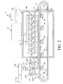
- FIG. 2 is a partial cross-sectional side view of the cooling device of the present invention and its peripheral devices.
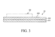
- FIG. 3 is an enlarged longitudinal sectional view of a belt of the cooling device shown in FIG.
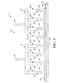
- FIG. 4 is a partial cross-sectional side view showing a second embodiment of the cooling device of the present invention.
- FIG. 5 is a partial cross-sectional side view showing a third embodiment of the cooling device of the present invention.
- FIG. 6 is a partial sectional side view showing a fourth embodiment of the cooling device of the present invention.
- FIG. 7 is a partial cross-sectional view of an IC package using the resin composition.
- FIG. 1 is a view showing a manufacturing process of a resin composition
- FIG. 2 is a partial sectional side view of a cooling device of the present invention and its peripheral devices
- FIG. 3 is an enlarged longitudinal sectional view of a belt of the cooling device shown in FIG.
- FIG. 7 is a partial cross-sectional view of an IC package using a resin composition.
- the upper side in FIGS. 2, 3, and 7 is “upper” or “upper”, and the lower side is “lower” or “lower”.
- the cooling device 1 of the present invention shown in FIG. 2 is a device used in a cooling step when producing a resin composition that finally becomes a molded body. Prior to the description of the cooling device 1, first, the entire manufacturing process until the resin composition is manufactured from the raw materials will be described.
- each material which is a raw material of a resin composition is prepared.
- the raw material includes a resin, a curing agent, and a filler (fine particles), and further includes a curing accelerator and a coupling agent as necessary.
- the resin an epoxy resin is preferable.
- epoxy resin examples include a cresol novolac type, a biphenyl type, a dicyclopentadiene type, a triphenolmethane type, and a polyaromatic ring type.
- Examples of the curing agent include a phenol novolac type, a phenol aralkyl type, a triphenolmethane type, and a polyaromatic ring type.
- Examples of the filler include fused silica (crushed and spherical), crystalline silica, alumina, and the like.
- Examples of the curing accelerator include phosphorus compounds and amine compounds.
- Examples of the coupling agent include silane compounds.
- the predetermined material may be abbreviate
- examples of other materials include a colorant, a release agent, a low stress agent, and a flame retardant.
- a predetermined material of raw materials is first pulverized (finely pulverized) with a pulverizer so as to have a predetermined particle size distribution.
- the raw material to be crushed is, for example, a raw material other than a filler such as a resin, a curing agent, and an accelerator, but a part of the filler can be added.
- a crusher a continuous rotation ball mill etc. can be used, for example.
- a predetermined material of the raw materials, for example, all or a part (remainder) of the filler can be subjected to a surface treatment.
- a surface treatment for example, a coupling agent or the like is attached to the surface of the filler.
- the fine pulverization and the surface treatment may be performed at the same time, or one of them may be performed first.
- mixing device Next, the respective materials are thoroughly mixed by a mixing device.
- a mixing apparatus for example, a high-speed mixer having rotating blades can be used.
- the mixed material is kneaded by the kneading apparatus 100.
- this kneading apparatus 100 for example, an extrusion kneader such as a single-screw kneading extruder, a biaxial kneading extruder, or a roll kneader such as a mixing roll can be used.
- the kneaded material (resin composition) which is the kneaded material is degassed.
- This deaeration can be performed by, for example, a vacuum pump (not shown) connected to the discharge port 101 for discharging the kneaded material of the kneading apparatus 100.
- the degassed lump kneaded material (hereinafter referred to as “kneaded material Q1”) is formed into a sheet shape by the forming apparatus 200 to obtain a sheet-like material (hereinafter referred to as “sheet material Q2”).
- sheet material Q2 As this shaping
- the sheet material Q2 is cooled by the cooling device 1. Thereby, the sheet material Q2 can be easily and reliably crushed in the next step.
- the cooling device 1 will be described in detail later.
- the sheet material is pulverized by a pulverizer so as to have a predetermined particle size distribution, thereby obtaining a powder material.
- a pulverizer for example, a hammer mill, a stone mill, a roll crusher, or the like can be used as the pulverizer.
- the powdered material can be compression-molded by a molded body manufacturing apparatus (tablet apparatus) to obtain a resin composition that is a molded body.
- this resin composition is used for covering (sealing) a semiconductor chip (IC chip) 901, for example, and becomes a mold part 902 constituting an exterior part of the semiconductor package (IC package) 900.
- the semiconductor chip 901 can be protected by the mold part 902.
- the resin composition is formed by, for example, transfer molding or the like and the semiconductor chip 901 is covered as a sealing material.
- a plurality of lead frames 903 protrude from the mold portion 902, and each lead frame 903 is formed of a wire 904 made of a conductive metal material such as gold. It is electrically connected to the semiconductor chip 901 via
- the tableting step may be omitted and a powdered material may be used as the resin composition.
- the sealing material can be formed by compression molding, injection molding, or the like.
- a cooling device 1 shown in FIG. 2 is a device for executing the cooling method of the present invention.
- the cooling device 1 is installed below the rollers 201 and 202, that is, on the downstream side from which the sheet material Q2 is discharged from the rollers 201 and 202.
- the sheet material Q ⁇ b> 2 pushed out from the rollers 201 and 202 quickly moves to the cooling device 1.
- the cooling device 1 can cool the sheet material Q2 while transporting it toward the next process.
- the following objectives are mentioned as the objective of cooling the sheet
- the sheet material Q2 extruded from the rollers 201 and 202 is heated, and the temperature immediately before being cooled by the cooling device 1 is about 40 to 60 ° C., for example. For this reason, the sheet material Q2 is soft. Further, since the sheet material Q2 is pulverized in the pulverization process which is the next process of the cooling process, it is necessary to cool the soft sheet material Q2 to make it hard in order to reliably perform the pulverization. This is the purpose of cooling the sheet material Q2 by the cooling device 1.
- the cooling device 1 includes a conveying unit 2 that conveys the sheet material Q ⁇ b> 2, a cooling unit 3 that cools the sheet material Q ⁇ b> 2, and a chamber 4 that maintains a cooling atmosphere by the cooling unit 3. .
- a conveying unit 2 that conveys the sheet material Q ⁇ b> 2
- a cooling unit 3 that cools the sheet material Q ⁇ b> 2
- a chamber 4 that maintains a cooling atmosphere by the cooling unit 3.
- the conveying means 2 is a belt conveyor that conveys the sheet material Q2 along its surface direction and sends it to the next process.
- the conveying means 2 includes a main pulley (carry roller) 21, a driven pulley (return roller) 22, a belt 23 wound around the main pulley 21 and the driven pulley 22, a main pulley 21 and a driven pulley 22. And a plurality of idle pulleys (belt conveyor rollers) 24 disposed between them.
- the main pulley 21 and the driven pulley 22 are spaced apart from each other via the chamber 4.
- a motor (not shown) is connected to the main pulley 21 and can rotate when the motor is driven. Further, when the main pulley 21 rotates, the driven pulley 22 can be rotated together with the main pulley 21 by transmitting the rotational force via the belt 23.
- the belt 23 has flexibility, and is configured to place and convey the sheet material Q2 as the main driving pulley 21 and the driven pulley 22 rotate.
- the belt 23 is configured by a laminated body having a base layer 231 and an outer layer 232.
- the underlayer 231 is a portion that is made of, for example, steel and serves as a core material of the belt 23.
- the outer layer 232 is a layer formed on the base layer 231 and positioned on the outermost side of the belt 23 and on which the sheet material Q2 is placed.
- the outer layer 232 is preferably made of a nonmetal. Thereby, in the process of conveying the sheet material Q2, even if friction is generated between the sheet material Q2 and the outer peripheral surface (surface) 233 of the outer layer 232, and the outer peripheral surface 233 is worn and partially cut, Naturally it is non-metallic.
- the cooling device 1 can reliably prevent such metal powder from being mixed into the sheet material Q2, and even if the scraped nonmetal is mixed into the sheet material Q2, the sheet material Q2 Is sufficiently durable to be used for the mold part 902 of the semiconductor package 900.
- the non-metallic material is not particularly limited.
- various rubber materials such as isoprene rubber, butadiene rubber, styrene-butadiene rubber, and various types such as styrene, polyolefin, polyvinyl chloride, and polyurethane.
- Thermoplastic elastomers can be mentioned, and one or more of these can be mixed and used.
- the base layer 231 may be ceramic coated.
- ceramics for example, oxide ceramics such as alumina, silica, titania, zirconia, yttria, and calcium phosphate, nitride ceramics such as silicon nitride, aluminum nitride, titanium nitride, and boron nitride, and carbide ceramics such as tungsten carbide Or the composite ceramics which combined two or more of these arbitrarily are mentioned.
- the outer layer 203 of the roller 201 and the outer layer 203 of the roller 202 of the molding device 200 disposed on the upstream side of the cooling device 1 are also made of ceramics. Thereby, mixing of the metal powder into the sheet material Q2 can be prevented more reliably.
- Each belt conveyor roller 24 is arranged at equal intervals, and supports the upper part of the belt 23. As a result, the belt 23 can be driven smoothly, and the belt 23 can be prevented from being bent (belt sagging).
- the cooling means 3 cools the sheet material Q2 conveyed by the conveying means 2.
- the cooling means 3 has a cooling ability to cool the sheet material Q2 so that the cooling rate is 0.2 to 5 ° C./second, preferably 0.5 to 1.5 ° C./second.
- the following configuration of each part and cooling conditions for each part are set.
- the cooling means 3 includes a blower unit 31 for blowing cool air G1 toward the sheet material Q2.
- the cooling means 3 (blower 31) includes a cool air generator 32 that generates cool air G1, a plurality of nozzles 33 that discharge the cool air G1 generated by the cool air generator 32, a cool air generator 32, and each nozzle 33. And a connecting pipe 34 to be connected.
- the cold air generating unit 32 is disposed outside the chamber 4.
- the cold air generating unit 32 is a device that receives the high pressure gas G0, cools the high pressure gas G0, and generates the cold air G1 from the high pressure gas G0.
- the configuration for cooling the high-pressure gas G0 is not particularly limited.
- the high-pressure gas G0 can be cooled with a refrigerant such as liquid nitrogen.
- it can also be set as the structure of a heat pump refrigerator.
- vapor compression, an absorption type, an adsorption type, a Stirling type, a chemical reaction type, a semiconductor, etc. are mentioned.
- the high-pressure gas G0 is not particularly limited, and examples thereof include air, carbon dioxide, or an inert gas such as nitrogen. From the viewpoint of safety, air is preferable.
- Each nozzle 33 is arranged inside the chamber 4 mainly along the conveying direction A of the sheet material Q2.
- the nozzle 33 may be arranged in the width direction of the sheet material Q2 (the back side in FIG. 2). Since the configuration of each nozzle 33 is substantially the same as each other, only one nozzle 33 will be representatively described below.
- the nozzle 33 is formed of a tubular body, and is arranged so that an opening at one end thereof faces downward, that is, toward the belt 23 side.
- the opening facing downward functions as an exhaust port 331 for discharging the cool air G1.
- the cool air G1 cold air
- the plurality of nozzles 33 described above are arranged along the conveyance direction A of the sheet material Q2, so that the sheet material Q2 comes into contact with the cold air G1 while being conveyed, and thus it is ensured without excess or deficiency. Quickly cooled.
- the temperature of the cool air G1 discharged from the nozzle 33 is not particularly limited, but is preferably set to ⁇ 40 to 0 ° C., for example, and more preferably set to ⁇ 20 to ⁇ 30 ° C. .
- Examples of such a temperature setting method include a method of adjusting a flow rate per unit time when the high-pressure gas G0 passes through the refrigerant, an adjustment of the set temperature of the refrigerator, and the like.
- the humidity of the cold air G1 discharged from the nozzle 33 is not particularly limited, but is preferably set to 10% or less, and more preferably 0 to 5%.
- the sheet material Q2 can be cooled under conditions lower than the dew point, and therefore, condensation can be prevented from occurring in the sheet material Q2.
- Examples of such a humidity setting method include a method in which a dehumidifying agent is provided in the cold air generating unit 32 and the high-pressure gas G0 is allowed to pass through the dehumidifying agent, and a method in which a dehumidifying device such as a dryer is provided.
- the pressure at which the cool air G1 is discharged from the nozzle 33 is not particularly limited, but is preferably set to 0.2 MPa or more, for example, 0.3 to 0.5 MPa. More preferred.
- a pressure setting method for example, a method is provided in which a valve is provided in the cold air generation unit 32, the open state of the valve is adjusted, and the pressure (flow rate) of the high-pressure gas G0 passing through the valve is adjusted. It is done.
- the sheet material Q2 is reliably cooled at the cooling rate.
- the sheet material Q2 that has entered at a temperature of 40 to 50 ° C. can be efficiently cooled, so that the sheet material Q2 can be quickly changed from a soft material to a hard material before moving to the crushing step. And it can change reliably.
- seat material Q2 can be grind
- the cooling device 1 can be a small device.
- the sheet material Q2 preferably has a thickness of 5 mm or less, and more preferably 0.5 to 3 mm. Thereby, it can cool more efficiently with the cooling device 1.
- the forming apparatus 200 has a function of cooling the sheet material Q2.
- the sheet material Q2 is preliminarily cooled before entering the cooling device 1, and can be further efficiently cooled by the cooling device 1.
- the chamber 4 can store the sheet material Q2 together with the belt 23 while the sheet material Q2 is being conveyed by the belt 23. Further, the chamber 4 is provided with an inlet 41 through which the sheet material Q2 enters and an outlet 42 through which the sheet material Q2 exits.
- the sheet material Q ⁇ b> 2 conveyed by the belt 23 enters the chamber 4 from the inlet 41, is cooled by the cooling means 3 in the chamber 4, and exits from the outlet 42.
- the cooling atmosphere by the cooling means 3 is maintained by the chamber 4, so that the sheet material Q2 can be cooled more efficiently. Further, it is possible to prevent foreign matter from entering the sheet material Q2.
- the wall part 43 which comprises the chamber 4 is covered with the heat insulating material, or the heat insulating material is embed
- FIG. 4 is a partial cross-sectional side view showing a second embodiment of the cooling device of the present invention.
- each nozzle 33 is installed to be inclined toward the downstream side in the transport direction A. As a result, the cool air G1 is discharged from each nozzle 33 from the opposite side to the transport direction A. That is, the flow of the cool air G1 is that of the counter flow.
- the cooling device 1 has a cooling efficiency equal to or higher than that of the first embodiment as compared with the case where the cold air G1 is blown from above vertically as in the first embodiment. Become.
- FIG. 5 is a partial cross-sectional side view showing a third embodiment of the cooling device of the present invention.
- This embodiment is the same as the first embodiment except that the configuration of the cooling means is different.
- the cooling means 3B shown in FIG. 5 is configured to blow cool air G1 on both sides of the sheet material Q2. This will be described below.
- a storage unit 35 that communicates with the cold air generation unit 32 via the belt 23 and temporarily stores the cold air G1 from the cold air generation unit 32 is disposed on the opposite side of the nozzles 33. ing.
- the storage unit 35 has a box shape, and an upper portion thereof is constituted by, for example, an elastic material packing 351.
- the packing 351 has a plate shape and is formed with a large number of through holes 352 penetrating in the thickness direction. Further, the packing 351 is in contact with the inner peripheral surface 234 of the belt 23.
- the belt 23 has a large number of through holes 235 penetrating in the thickness direction.
- the size of each through hole 235 is larger than the size of each through hole 352 of the storage portion 35.
- the cold air G1 is discharged from the through hole 235.
- the cool air G1 can cool the sheet material Q2 from the lower surface side.
- the cool air G1 from each nozzle 33 can cool the sheet material Q2 from the upper surface side.
- the cooling effect can be increased by increasing the contact area between the sheet material Q2 and the cool air G1. Further, the sheet material Q2 can be cooled from both sides thereof, so that the sheet material Q2 is warped during cooling, and the nozzle 33 and the sheet material Q2 are prevented from coming into contact with each other during the cooling to cause clogging. be able to.
- FIG. 6 is a partial sectional side view showing a fourth embodiment of the cooling device of the present invention.
- the cooling means 3C shown in FIG. 6 has nozzles 33a and 33b for discharging cool air G2 and G3 having different temperatures, respectively.
- the temperature of the cool air G2 discharged from the nozzle 33a is higher than that of the cool air G3 discharged from the nozzle 33b.
- the temperature of the cool air G2 can be set to ⁇ 20 to 0 ° C.
- the temperature of the cool air G3 can be set to ⁇ 40 to ⁇ 20 ° C.
- the sheet material Q2 is cooled in stages in the process of being conveyed. Thereby, it is possible to prevent the sheet material Q2 from being rapidly cooled at an excessively low temperature, and thus it is possible to prevent unintentional alteration of the sheet material Q2. Further, it is possible to prevent the sheet material Q2 from being warped during cooling and causing the nozzles 33a and 33b and the sheet material Q2 to come into contact with each other to cause clogging. Since the cooling effect is affected by the temperature difference between the object to be cooled and the refrigerant, the cooling can be performed in an appropriate low temperature state by such a configuration, so that there is no waste in energy efficiency.
- each part which comprises a cooling device can be substituted with the thing of the arbitrary structures which can exhibit the same function.
- arbitrary components may be added.
- cooling device and the cooling method of the present invention may be a combination of any two or more configurations (features) of the above embodiments.
- the belt of the cooling device of the present invention is composed of a laminate, and the outermost layer is composed of a nonmetal such as an elastic material, but is not limited thereto.
- a nonmetal such as an elastic material
- it may be composed of a single layer, and the whole may be composed of a nonmetal.
- the cooling means of the cooling device of the present invention has a plurality of nozzles arranged in each embodiment, the present invention is not limited to this.
- one nozzle may be arranged. .
- a resin composition having a temperature of 40 to 50 ° C. can be efficiently cooled.
- the soft resin composition is cooled before pulverization, It can be quickly and reliably changed to a hard one.
- a hard resin composition can be grind
- the transport means has a belt for placing and transporting the resin composition, and at least the surface of the belt is made of a non-metal, in the process of transporting the resin composition, Even if friction occurs with the surface of the belt and the surface is worn away and part thereof is scraped off, the scraped part is naturally non-metallic.
- the belt itself is made of steel, metal powder is generated from the surface due to wear as described above in the process of transporting the resin composition, and the metal powder is still sufficiently cooled. There is a possibility that it may be mixed into a soft resin composition.
Landscapes
- Engineering & Computer Science (AREA)
- Mechanical Engineering (AREA)
- Physics & Mathematics (AREA)
- Thermal Sciences (AREA)
- Processing And Handling Of Plastics And Other Materials For Molding In General (AREA)
- Casting Or Compression Moulding Of Plastics Or The Like (AREA)
- Heating, Cooling, Or Curing Plastics Or The Like In General (AREA)
Abstract
Description
(1) シート状に成形された樹脂組成物を、その面方向に沿って搬送する搬送手段と、
前記搬送手段により搬送されている前記樹脂組成物を冷却する冷却手段とを備え、
前記樹脂組成物は、前記冷却手段で冷却される直前の温度が40~60℃のものであり、
前記冷却手段は、前記樹脂組成物の冷却速度が0.2~5℃/秒となるように冷却する冷却能を有することを特徴とする冷却装置。
前記ベルトは、その少なくとも表面が非金属で構成されている上記(1)ないし(9)のいずれかに記載の冷却装置。
当該冷却装置は、前記一対のローラから前記樹脂組成物が排出される下流側に設置されている上記(1)ないし(12)のいずれかに記載の冷却装置。
前記樹脂組成物は、当該冷却方法で冷却される直前の温度が40~60℃のものであり、
前記樹脂組成物の冷却速度が0.2~5℃/秒となるように冷却することを特徴とする冷却方法。
図1は、樹脂組成物の製造工程を示す図、図2は、本発明の冷却装置およびその周辺の装置の部分断面側面図、図3は、図2に示す冷却装置のベルトの拡大縦断面図、図7は、樹脂組成物を用いたICパッケージの部分断面図である。なお、以下では、説明の都合上、図2、図3、図7中(図4~図6についても同様)の上側を「上」または「上方」、下側を「下」または「下方」と言う。
原材料は、樹脂と、硬化剤と、充填材(微粒子)とを有し、さらに必要に応じて、硬化促進剤と、カップリング剤等を有している。樹脂としては、エポキシ樹脂が好ましい。
カップリング剤としては、例えば、シラン化合物等が挙げられる。
図1に示すように、原材料のうちの所定の材料については、まず、粉砕装置により、所定の粒度分布となるように粉砕(微粉砕)する。この粉砕する原材料としては、例えば、樹脂、硬化剤、促進剤等の充填材以外の原材料であるが、充填材の一部を加えることもできる。また、粉砕装置としては、例えば、連続式回転ボールミル等を用いることができる。
原材料のうちの所定の材料、例えば、充填材の全部または一部(残部)については、表面処理を施すことができる。この表面処理としては、例えば、充填材の表面にカップリング剤等を付着させる。なお、前記微粉砕と表面処理とは、同時に行ってもよく、また、いずれか一方を先に行ってもよい。
次に、混合装置により、前記各材料を完全に混合する。この混合装置としては、例えば、回転羽根を有する高速混合機等を用いることができる。
次に、混練装置100により、前記混合された材料を混練する。この混練装置100としては、例えば、1軸型混練押出機、2軸型混練押出機等の押出混練機やミキシングロール等のロール式混練機を用いることができる。
次に、前記混練された材料である混練物(樹脂組成物)に対し脱気を行う。この脱気は、例えば混練装置100の前記混練された材料を排出する排出口101に接続された真空ポンプ(図示せず)によって行うことができる。
次に、前記脱気された塊状の混練物(以下「混練物Q1」と言う)を、成形装置200でシート状に成形し、シート状の材料(以下「シート材Q2」と言う)を得る。この成形装置200としては、例えば、図2に示すように、混練装置100の排出口101の下方(下流側)に配置されたローラ201、202を有する装置を用いることができる。図2に示す構成では、ローラ201とローラ202との間で、混練装置100より排出された混練物Q1を加圧してシート状に成形することができる。
次に、冷却装置1により、シート材Q2を冷却する。これにより、次工程でシート材Q2の粉砕を容易かつ確実に行うことができる。なお、冷却装置1については、後に詳述する。
次に、粉砕装置により、シート状の材料を所定の粒度分布となるように粉砕し、粉末状の材料を得る。この粉砕装置としては、例えば、ハンマーミル、石臼式磨砕機、ロールクラッシャー等を用いることができる。
次に、成形体製造装置(打錠装置)により、前記粉末状の材料を圧縮成形し、成形体である樹脂組成物を得ることができる。
図2に示す冷却装置1は、本発明の冷却方法を実行するための装置である。この冷却装置1は、ローラ201、202の下方、すなわち、ローラ201、202からシート材Q2が排出される下流側に設置されている。これにより、ローラ201、202から押し出されたシート材Q2が冷却装置1に迅速に移行する。そして、冷却装置1は、シート材Q2を次工程へ向けて搬送しつつ、冷却することができる。なお、シート材Q2を冷却する目的としては、次のような目的が挙げられる。
外層232は、下地層231上に形成され、ベルト23の最も外側に位置して、シート材Q2が載置される層である。この外層232は、非金属で構成されていることが好ましい。これにより、シート材Q2を搬送する過程で、シート材Q2と外層232の外周面(表面)233との間で摩擦が生じ、外周面233が摩耗して一部が削れたとしても、その削れたものは、当然に非金属である。これに対し、例えばベルト23自体がスチール製である場合には、シート材Q2を搬送する過程で、前述したような摩耗により、当該上面から金属粉末が生じ、その金属粉末が、未だ十分に冷却されていない軟質の状態のシート材Q2に混入してしまうおそれがある。しかしながら、冷却装置1では、このような金属粉末がシート材Q2に混入するのを確実に防止することができ、また、前記削れた非金属がシート材Q2に混入しても、そのシート材Q2は、半導体パッケージ900のモールド部902に使用するのに十分耐え得るものである。
図4は、本発明の冷却装置の第2実施形態を示す部分断面側面図である。
図4に示す冷却手段3Aでは、各ノズル33がそれぞれ搬送方向Aの下流側に向かって傾斜して設置されている。これにより、各ノズル33からは、それぞれ、冷気G1が搬送方向Aと反対側から排出される。すなわち、冷気G1は、その流れがカウンタフローのものとなる。
図5は、本発明の冷却装置の第3実施形態を示す部分断面側面図である。
図5に示す冷却手段3Bは、シート材Q2に対しその両面側からそれぞれ冷気G1を吹き付けるよう構成されている。以下、これについて説明する。
図6は、本発明の冷却装置の第4実施形態を示す部分断面側面図である。
図6に示す冷却手段3Cでは、互いに温度が異なる冷気G2およびG3をそれぞれ排出するノズル33aおよび33bを有している。例えば、ノズル33aから排出される冷気G2は、ノズル33bから排出される冷気G3よりも温度が高い。この場合、例えば、冷気G2の温度を-20~0℃、冷気G3の温度を-40~-20℃とすることができる。また、冷気G2による雰囲気と冷気G3による雰囲気とで別のチャンバ4を備えていてもよい。
Claims (16)
- シート状に成形された樹脂組成物を、その面方向に沿って搬送する搬送手段と、
前記搬送手段により搬送されている前記樹脂組成物を冷却する冷却手段とを備え、
前記樹脂組成物は、前記冷却手段で冷却される直前の温度が40~60℃のものであり、
前記冷却手段は、前記樹脂組成物の冷却速度が0.2~5℃/秒となるように冷却する冷却能を有することを特徴とする冷却装置。 - 前記冷却手段は、前記樹脂組成物に向けて-40~0℃の冷気を排出する、少なくとも1つの排気口を有する送風部を備える請求項1に記載の冷却装置。
- 前記冷気は、その湿度が10%以下のものである請求項2に記載の冷却装置。
- 前記排気口から前記冷気が排出される際、その圧力は、0.2MPa以上である請求項2または3に記載の冷却装置。
- 前記排気口は、前記樹脂組成物の搬送方向に沿って複数配置されている請求項2ないし4のいずれかに記載の冷却装置。
- 前記排気口は、前記冷気を上方から排出する請求項2ないし5のいずれかに記載の冷却装置。
- 前記排気口は、前記冷気を前記樹脂組成物の搬送方向と反対側から排出する請求項2ないし5のいずれかに記載の冷却装置。
- 前記冷却手段は、前記樹脂組成物に対しその両面側からそれぞれ前記冷気を吹き付けるよう構成されている請求項2ないし7のいずれかに記載の冷却装置。
- 前記冷却手段は、前記冷気の温度を段階的に下げていくよう構成されている請求項2ないし8のいずれかに記載の冷却装置。
- 前記搬送手段は、互いに離間して配置された一対のプーリと、該一対のプーリ間に掛け回され、該各プーリが回転することにより、前記樹脂組成物を載置して搬送するベルトとを有し、
前記ベルトは、その少なくとも表面が非金属で構成されている請求項1ないし9のいずれかに記載の冷却装置。 - 前記ベルトは、積層体で構成され、その最も外側に位置する外層が前記非金属で構成されている請求項10に記載の冷却装置。
- 前記樹脂組成物が前記ベルトで搬送されている間、前記樹脂組成物を前記ベルトごと格納し、前記冷却手段による冷却雰囲気を維持するチャンバをさらに備える請求項1ないし11のいずれかに記載の冷却装置。
- 前記樹脂組成物は、混練装置で混練され、その混練物が一対のローラ間で加圧されてシート状に成形されたものであり、
当該冷却装置は、前記一対のローラから前記樹脂組成物が排出される下流側に設置されている請求項1ないし12のいずれかに記載の冷却装置。 - 前記樹脂組成物は、その厚さが5mm以下である請求項1ないし13のいずれかに記載の冷却装置。
- 前記樹脂組成物は、ICパッケージの外装部を構成するモールド部となるものである請求項1ないし14のいずれかに記載の冷却装置。
- シート状に成形された樹脂組成物を、その面方向に沿って搬送しつつ、冷却する冷却方法であって、
前記樹脂組成物は、当該冷却方法で冷却される直前の温度が40~60℃のものであり、
前記樹脂組成物の冷却速度が0.2~5℃/秒となるように冷却することを特徴とする冷却方法。
Priority Applications (4)
| Application Number | Priority Date | Filing Date | Title |
|---|---|---|---|
| CN201180009611.7A CN102762345B (zh) | 2010-03-05 | 2011-02-21 | 冷却装置及冷却方法 |
| KR1020127020475A KR101809765B1 (ko) | 2010-03-05 | 2011-02-21 | 냉각장치 및 냉각방법 |
| SG2012062766A SG183478A1 (en) | 2010-03-05 | 2011-02-21 | Cooling apparatus and cooling method |
| US13/580,258 US9849613B2 (en) | 2010-03-05 | 2011-02-21 | Conveying and cooling apparatus for a resin composition and conveying and cooling method for a resin composition |
Applications Claiming Priority (2)
| Application Number | Priority Date | Filing Date | Title |
|---|---|---|---|
| JP2010049762A JP5593741B2 (ja) | 2010-03-05 | 2010-03-05 | 冷却装置および冷却方法 |
| JP2010-049762 | 2010-03-05 |
Publications (1)
| Publication Number | Publication Date |
|---|---|
| WO2011108387A1 true WO2011108387A1 (ja) | 2011-09-09 |
Family
ID=44542043
Family Applications (1)
| Application Number | Title | Priority Date | Filing Date |
|---|---|---|---|
| PCT/JP2011/053698 Ceased WO2011108387A1 (ja) | 2010-03-05 | 2011-02-21 | 冷却装置および冷却方法 |
Country Status (8)
| Country | Link |
|---|---|
| US (1) | US9849613B2 (ja) |
| JP (1) | JP5593741B2 (ja) |
| KR (1) | KR101809765B1 (ja) |
| CN (1) | CN102762345B (ja) |
| MY (1) | MY155894A (ja) |
| SG (1) | SG183478A1 (ja) |
| TW (1) | TWI524481B (ja) |
| WO (1) | WO2011108387A1 (ja) |
Cited By (1)
| Publication number | Priority date | Publication date | Assignee | Title |
|---|---|---|---|---|
| US10471627B2 (en) * | 2015-12-15 | 2019-11-12 | Compagnie Generale Des Etablissments Michelin | Process and system for controlling the addition of water during a mixing cycle for producing a rubber mixture |
Families Citing this family (15)
| Publication number | Priority date | Publication date | Assignee | Title |
|---|---|---|---|---|
| JP5691215B2 (ja) * | 2010-03-26 | 2015-04-01 | 住友ベークライト株式会社 | 粉砕装置 |
| JP6123528B2 (ja) * | 2013-02-05 | 2017-05-10 | 日立化成株式会社 | 搬送装置 |
| JP6096024B2 (ja) * | 2013-03-26 | 2017-03-15 | リンテック株式会社 | シート剥離装置及びシート剥離方法 |
| RU2653728C1 (ru) | 2013-11-26 | 2018-05-14 | Интерконтинентал Грейт Брендс Ллк | Система и способ регулирования температуры жевательной резинки |
| CN106839598B (zh) * | 2017-03-07 | 2022-09-27 | 宁波华斯特林电机制造有限公司 | 一种网带冰箱 |
| WO2018180409A1 (ja) * | 2017-03-28 | 2018-10-04 | ユニプレス株式会社 | 成形品の冷却方法及び冷却装置 |
| CN107627711A (zh) * | 2017-11-03 | 2018-01-26 | 浙江海啊汽车用品有限公司 | 一种布料和橡胶火焰复合机 |
| WO2019154448A1 (de) * | 2018-02-12 | 2019-08-15 | Harburg-Freudenberger Maschinenbau Gmbh | Vorrichtung zur kühlung von extrudaten |
| CN108426411A (zh) * | 2018-04-16 | 2018-08-21 | 南京汇康玻璃制品有限公司 | 一种玻璃印刷连线冷却装置 |
| CN108748773B (zh) * | 2018-05-23 | 2020-06-05 | 浙江利帆家具有限公司 | 基于CaCO3纳米SiO2改性的HDPE家具料的生产设备及工艺 |
| US11273940B2 (en) | 2019-02-06 | 2022-03-15 | Owens-Brockway Glass Container Inc. | Cooling sealed packages after hot filling and sealing |
| KR102336066B1 (ko) * | 2020-06-08 | 2021-12-07 | 코스맥스 주식회사 | 입체 형상의 화장품 제조 장치 |
| CN111941684B (zh) * | 2020-08-28 | 2024-08-30 | 佛山市沧龙新材料有限公司 | 一种母粒生产线风冷装置 |
| CN112265782A (zh) * | 2020-10-29 | 2021-01-26 | 盐城健牌科技有限公司 | 一种用于汽车密封条生产的快速冷却传送装置 |
| CN113959160A (zh) * | 2021-10-25 | 2022-01-21 | 广东亨通光电科技有限公司 | 一种拉远光缆生产设备 |
Citations (12)
| Publication number | Priority date | Publication date | Assignee | Title |
|---|---|---|---|---|
| JPH0543622A (ja) * | 1991-08-09 | 1993-02-23 | Idemitsu Kosan Co Ltd | スチレン系樹脂成形体及びその製造方法 |
| JPH06347162A (ja) * | 1993-06-08 | 1994-12-20 | Mitsubishi Kasei Eng Co | 回転円筒型処理装置 |
| JPH09155863A (ja) * | 1995-12-08 | 1997-06-17 | Shin Kobe Electric Mach Co Ltd | プリプレグの製造装置 |
| JPH09204004A (ja) * | 1996-01-29 | 1997-08-05 | Konica Corp | 写真用ポリエステルフィルム支持体およびその製造方法 |
| JP2000246785A (ja) * | 1999-02-26 | 2000-09-12 | Tokuyama Corp | ポリプロピレンシートの製造方法 |
| JP2000246732A (ja) * | 1999-02-26 | 2000-09-12 | Nitto Denko Corp | ポリオレフィン溶融混練物の製造方法及びポリオレフィンシート |
| JP2005099097A (ja) * | 2003-09-22 | 2005-04-14 | Fuji Photo Film Co Ltd | 光学フィルム及びその製造方法並びに該光学フィルムを用いた偏光板 |
| JP2006187873A (ja) * | 2004-12-28 | 2006-07-20 | Sumitomo Bakelite Co Ltd | 半導体封止用樹脂タブレットおよびその製造方法、樹脂成形体の製造方法ならびに半導体装置 |
| JP2006264325A (ja) * | 2005-02-25 | 2006-10-05 | Toray Ind Inc | 熱可塑性樹脂ペレットの製造装置およびその製造方法 |
| JP2006297701A (ja) * | 2005-04-19 | 2006-11-02 | Hitachi Chem Co Ltd | 半導体封止用エポキシ樹脂組成物の製造方法、半導体封止用エポキシ樹脂組成物及びそれを用いた電子部品装置 |
| WO2007069474A1 (ja) * | 2005-12-12 | 2007-06-21 | Konica Minolta Opto, Inc. | 偏光板の製造方法、偏光板及び液晶表示装置 |
| JP2007190905A (ja) * | 2005-12-19 | 2007-08-02 | Hitachi Chem Co Ltd | 混合装置、混合物および半導体装置 |
Family Cites Families (19)
| Publication number | Priority date | Publication date | Assignee | Title |
|---|---|---|---|---|
| BE630358A (ja) * | 1962-05-04 | |||
| US3267585A (en) * | 1965-03-03 | 1966-08-23 | Rudolph E Futer | Changing the temperatures of objects by gas jets |
| US3393532A (en) * | 1966-10-20 | 1968-07-23 | Design Process Engineering Inc | Refrigerated conveyor system |
| JPS545819B2 (ja) * | 1974-07-11 | 1979-03-22 | ||
| US4923658A (en) * | 1985-12-27 | 1990-05-08 | Huels Troisdorf Ag | Process for the production of dyed, flat articles from thermoplastic synthetic resins |
| US5357014A (en) | 1991-08-09 | 1994-10-18 | Idemitsu Kosan Co., Ltd. | Styrenic resin molding and process for producing same |
| JP3175979B2 (ja) * | 1992-09-14 | 2001-06-11 | 株式会社東芝 | 樹脂封止型半導体装置 |
| US20020028340A1 (en) * | 1996-10-22 | 2002-03-07 | Atsushi Fujii | Soft transparent polyolefin resin sheet and method for producing the same |
| US6148618A (en) * | 1997-04-25 | 2000-11-21 | Frigoscandia Equipment Ab | Method and apparatus for surface freezing |
| DE69833486T2 (de) * | 1997-05-30 | 2006-07-20 | Alcoa Inc. | Verfahren zur beschichtung von aluminiumbändern |
| EP1048628A1 (de) * | 1999-04-30 | 2000-11-02 | Schott Glas | Polymerbeschichtete Dünnglasfoliensubstrate |
| JP2002086544A (ja) | 2000-09-20 | 2002-03-26 | Sekisui Chem Co Ltd | 熱可塑性複合材料の押出成形方法及びその押出装置 |
| JP3745632B2 (ja) | 2001-03-13 | 2006-02-15 | いすず化工機株式会社 | スクリーンコンベア |
| US7223806B2 (en) * | 2001-03-14 | 2007-05-29 | Sumitomo Chemical Company, Limited | Manufacturing method of film-like materials of resin and film-like materials of resin |
| US20040216470A1 (en) * | 2001-06-15 | 2004-11-04 | Michael Thomas | Cryogenic gas-assisted mechanical refrigeration cooling system apparatus and method |
| TWI331087B (en) * | 2003-03-06 | 2010-10-01 | Sumitomo Chemical Co | Method for producing laminated porous polyolefin film and laminated porous polyolefin film |
| JP2006231549A (ja) | 2005-02-22 | 2006-09-07 | Hitachi Chem Co Ltd | 樹脂、樹脂の製造方法及び樹脂の製造 |
| JP2007062334A (ja) * | 2005-09-02 | 2007-03-15 | Fujifilm Corp | セルロースアシレート樹脂フィルム及びその製造方法 |
| US8052842B2 (en) * | 2008-01-24 | 2011-11-08 | Agriboard Industries | Method for making a compressed structural fiberboard |
-
2010
- 2010-03-05 JP JP2010049762A patent/JP5593741B2/ja active Active
-
2011
- 2011-02-21 KR KR1020127020475A patent/KR101809765B1/ko active Active
- 2011-02-21 MY MYPI2012003759A patent/MY155894A/en unknown
- 2011-02-21 CN CN201180009611.7A patent/CN102762345B/zh active Active
- 2011-02-21 US US13/580,258 patent/US9849613B2/en active Active
- 2011-02-21 SG SG2012062766A patent/SG183478A1/en unknown
- 2011-02-21 WO PCT/JP2011/053698 patent/WO2011108387A1/ja not_active Ceased
- 2011-03-04 TW TW100107335A patent/TWI524481B/zh active
Patent Citations (12)
| Publication number | Priority date | Publication date | Assignee | Title |
|---|---|---|---|---|
| JPH0543622A (ja) * | 1991-08-09 | 1993-02-23 | Idemitsu Kosan Co Ltd | スチレン系樹脂成形体及びその製造方法 |
| JPH06347162A (ja) * | 1993-06-08 | 1994-12-20 | Mitsubishi Kasei Eng Co | 回転円筒型処理装置 |
| JPH09155863A (ja) * | 1995-12-08 | 1997-06-17 | Shin Kobe Electric Mach Co Ltd | プリプレグの製造装置 |
| JPH09204004A (ja) * | 1996-01-29 | 1997-08-05 | Konica Corp | 写真用ポリエステルフィルム支持体およびその製造方法 |
| JP2000246785A (ja) * | 1999-02-26 | 2000-09-12 | Tokuyama Corp | ポリプロピレンシートの製造方法 |
| JP2000246732A (ja) * | 1999-02-26 | 2000-09-12 | Nitto Denko Corp | ポリオレフィン溶融混練物の製造方法及びポリオレフィンシート |
| JP2005099097A (ja) * | 2003-09-22 | 2005-04-14 | Fuji Photo Film Co Ltd | 光学フィルム及びその製造方法並びに該光学フィルムを用いた偏光板 |
| JP2006187873A (ja) * | 2004-12-28 | 2006-07-20 | Sumitomo Bakelite Co Ltd | 半導体封止用樹脂タブレットおよびその製造方法、樹脂成形体の製造方法ならびに半導体装置 |
| JP2006264325A (ja) * | 2005-02-25 | 2006-10-05 | Toray Ind Inc | 熱可塑性樹脂ペレットの製造装置およびその製造方法 |
| JP2006297701A (ja) * | 2005-04-19 | 2006-11-02 | Hitachi Chem Co Ltd | 半導体封止用エポキシ樹脂組成物の製造方法、半導体封止用エポキシ樹脂組成物及びそれを用いた電子部品装置 |
| WO2007069474A1 (ja) * | 2005-12-12 | 2007-06-21 | Konica Minolta Opto, Inc. | 偏光板の製造方法、偏光板及び液晶表示装置 |
| JP2007190905A (ja) * | 2005-12-19 | 2007-08-02 | Hitachi Chem Co Ltd | 混合装置、混合物および半導体装置 |
Cited By (1)
| Publication number | Priority date | Publication date | Assignee | Title |
|---|---|---|---|---|
| US10471627B2 (en) * | 2015-12-15 | 2019-11-12 | Compagnie Generale Des Etablissments Michelin | Process and system for controlling the addition of water during a mixing cycle for producing a rubber mixture |
Also Published As
| Publication number | Publication date |
|---|---|
| US9849613B2 (en) | 2017-12-26 |
| SG183478A1 (en) | 2012-09-27 |
| TW201145473A (en) | 2011-12-16 |
| CN102762345B (zh) | 2015-07-29 |
| CN102762345A (zh) | 2012-10-31 |
| JP5593741B2 (ja) | 2014-09-24 |
| KR20130028047A (ko) | 2013-03-18 |
| JP2011183618A (ja) | 2011-09-22 |
| MY155894A (en) | 2015-12-15 |
| KR101809765B1 (ko) | 2017-12-15 |
| US20120318002A1 (en) | 2012-12-20 |
| TWI524481B (zh) | 2016-03-01 |
Similar Documents
| Publication | Publication Date | Title |
|---|---|---|
| JP5593741B2 (ja) | 冷却装置および冷却方法 | |
| KR101825758B1 (ko) | 분쇄장치 및 분쇄방법 | |
| CN106268501A (zh) | 粒子制造装置、粒子制造方法及半导体封装用树脂组合物的制造方法 | |
| KR101859781B1 (ko) | 혼련 장치 및 반도체 씰링용 수지 조성물의 제조 방법 | |
| KR101832514B1 (ko) | 성형장치 및 성형방법 | |
| JP5671807B2 (ja) | 脱気装置 |
Legal Events
| Date | Code | Title | Description |
|---|---|---|---|
| WWE | Wipo information: entry into national phase |
Ref document number: 201180009611.7 Country of ref document: CN |
|
| 121 | Ep: the epo has been informed by wipo that ep was designated in this application |
Ref document number: 11750499 Country of ref document: EP Kind code of ref document: A1 |
|
| ENP | Entry into the national phase |
Ref document number: 20127020475 Country of ref document: KR Kind code of ref document: A |
|
| WWE | Wipo information: entry into national phase |
Ref document number: 13580258 Country of ref document: US |
|
| NENP | Non-entry into the national phase |
Ref country code: DE |
|
| WWE | Wipo information: entry into national phase |
Ref document number: 1201004296 Country of ref document: TH |
|
| 122 | Ep: pct application non-entry in european phase |
Ref document number: 11750499 Country of ref document: EP Kind code of ref document: A1 |