WO2011108320A1 - ホロー出力軸と被駆動軸との連結構造、及び減速機 - Google Patents
ホロー出力軸と被駆動軸との連結構造、及び減速機 Download PDFInfo
- Publication number
- WO2011108320A1 WO2011108320A1 PCT/JP2011/051857 JP2011051857W WO2011108320A1 WO 2011108320 A1 WO2011108320 A1 WO 2011108320A1 JP 2011051857 W JP2011051857 W JP 2011051857W WO 2011108320 A1 WO2011108320 A1 WO 2011108320A1
- Authority
- WO
- WIPO (PCT)
- Prior art keywords
- output shaft
- hollow output
- hollow
- shaft
- driven shaft
- Prior art date
- Legal status (The legal status is an assumption and is not a legal conclusion. Google has not performed a legal analysis and makes no representation as to the accuracy of the status listed.)
- Ceased
Links
Images



Classifications
-
- F—MECHANICAL ENGINEERING; LIGHTING; HEATING; WEAPONS; BLASTING
- F16—ENGINEERING ELEMENTS AND UNITS; GENERAL MEASURES FOR PRODUCING AND MAINTAINING EFFECTIVE FUNCTIONING OF MACHINES OR INSTALLATIONS; THERMAL INSULATION IN GENERAL
- F16H—GEARING
- F16H57/00—General details of gearing
- F16H57/04—Features relating to lubrication or cooling or heating
- F16H57/042—Guidance of lubricant
- F16H57/043—Guidance of lubricant within rotary parts, e.g. axial channels or radial openings in shafts
-
- F—MECHANICAL ENGINEERING; LIGHTING; HEATING; WEAPONS; BLASTING
- F16—ENGINEERING ELEMENTS AND UNITS; GENERAL MEASURES FOR PRODUCING AND MAINTAINING EFFECTIVE FUNCTIONING OF MACHINES OR INSTALLATIONS; THERMAL INSULATION IN GENERAL
- F16D—COUPLINGS FOR TRANSMITTING ROTATION; CLUTCHES; BRAKES
- F16D1/00—Couplings for rigidly connecting two coaxial shafts or other movable machine elements
- F16D1/06—Couplings for rigidly connecting two coaxial shafts or other movable machine elements for attachment of a member on a shaft or on a shaft-end
- F16D1/08—Couplings for rigidly connecting two coaxial shafts or other movable machine elements for attachment of a member on a shaft or on a shaft-end with clamping hub; with hub and longitudinal key
- F16D1/0876—Couplings for rigidly connecting two coaxial shafts or other movable machine elements for attachment of a member on a shaft or on a shaft-end with clamping hub; with hub and longitudinal key with axial keys and no other radial clamping
-
- F—MECHANICAL ENGINEERING; LIGHTING; HEATING; WEAPONS; BLASTING
- F16—ENGINEERING ELEMENTS AND UNITS; GENERAL MEASURES FOR PRODUCING AND MAINTAINING EFFECTIVE FUNCTIONING OF MACHINES OR INSTALLATIONS; THERMAL INSULATION IN GENERAL
- F16B—DEVICES FOR FASTENING OR SECURING CONSTRUCTIONAL ELEMENTS OR MACHINE PARTS TOGETHER, e.g. NAILS, BOLTS, CIRCLIPS, CLAMPS, CLIPS OR WEDGES; JOINTS OR JOINTING
- F16B2200/00—Constructional details of connections not covered for in other groups of this subclass
- F16B2200/60—Coupler sealing means
-
- F—MECHANICAL ENGINEERING; LIGHTING; HEATING; WEAPONS; BLASTING
- F16—ENGINEERING ELEMENTS AND UNITS; GENERAL MEASURES FOR PRODUCING AND MAINTAINING EFFECTIVE FUNCTIONING OF MACHINES OR INSTALLATIONS; THERMAL INSULATION IN GENERAL
- F16D—COUPLINGS FOR TRANSMITTING ROTATION; CLUTCHES; BRAKES
- F16D2300/00—Special features for couplings or clutches
- F16D2300/06—Lubrication details not provided for in group F16D13/74
-
- F—MECHANICAL ENGINEERING; LIGHTING; HEATING; WEAPONS; BLASTING
- F16—ENGINEERING ELEMENTS AND UNITS; GENERAL MEASURES FOR PRODUCING AND MAINTAINING EFFECTIVE FUNCTIONING OF MACHINES OR INSTALLATIONS; THERMAL INSULATION IN GENERAL
- F16H—GEARING
- F16H1/00—Toothed gearings for conveying rotary motion
- F16H1/02—Toothed gearings for conveying rotary motion without gears having orbital motion
- F16H1/04—Toothed gearings for conveying rotary motion without gears having orbital motion involving only two intermeshing members
- F16H1/12—Toothed gearings for conveying rotary motion without gears having orbital motion involving only two intermeshing members with non-parallel axes
- F16H1/14—Toothed gearings for conveying rotary motion without gears having orbital motion involving only two intermeshing members with non-parallel axes comprising conical gears only
-
- F—MECHANICAL ENGINEERING; LIGHTING; HEATING; WEAPONS; BLASTING
- F16—ENGINEERING ELEMENTS AND UNITS; GENERAL MEASURES FOR PRODUCING AND MAINTAINING EFFECTIVE FUNCTIONING OF MACHINES OR INSTALLATIONS; THERMAL INSULATION IN GENERAL
- F16H—GEARING
- F16H57/00—General details of gearing
- F16H57/04—Features relating to lubrication or cooling or heating
- F16H57/048—Type of gearings to be lubricated, cooled or heated
- F16H57/0493—Gearings with spur or bevel gears
- F16H57/0495—Gearings with spur or bevel gears with fixed gear ratio
-
- Y—GENERAL TAGGING OF NEW TECHNOLOGICAL DEVELOPMENTS; GENERAL TAGGING OF CROSS-SECTIONAL TECHNOLOGIES SPANNING OVER SEVERAL SECTIONS OF THE IPC; TECHNICAL SUBJECTS COVERED BY FORMER USPC CROSS-REFERENCE ART COLLECTIONS [XRACs] AND DIGESTS
- Y10—TECHNICAL SUBJECTS COVERED BY FORMER USPC
- Y10T—TECHNICAL SUBJECTS COVERED BY FORMER US CLASSIFICATION
- Y10T403/00—Joints and connections
- Y10T403/70—Interfitted members
-
- Y—GENERAL TAGGING OF NEW TECHNOLOGICAL DEVELOPMENTS; GENERAL TAGGING OF CROSS-SECTIONAL TECHNOLOGIES SPANNING OVER SEVERAL SECTIONS OF THE IPC; TECHNICAL SUBJECTS COVERED BY FORMER USPC CROSS-REFERENCE ART COLLECTIONS [XRACs] AND DIGESTS
- Y10—TECHNICAL SUBJECTS COVERED BY FORMER USPC
- Y10T—TECHNICAL SUBJECTS COVERED BY FORMER US CLASSIFICATION
- Y10T403/00—Joints and connections
- Y10T403/70—Interfitted members
- Y10T403/7018—Interfitted members including separably interposed key
Definitions
- the present invention relates to a connection structure between a hollow output shaft and a driven shaft inserted into a hollow portion of the hollow output shaft, and a speed reducer that is optimal for realizing the connection structure.
- Patent Document 1 discloses a speed reducer 14 having a hollow output shaft 12 having a hollow portion 10 as shown in FIG. Such a reducer 14 is used in such a manner that the driven shaft 16 is directly inserted into the hollow portion 10 of the hollow output shaft 12.
- the inner diameter of the hollow output shaft 12 is set to be slightly larger than the outer diameter of the driven shaft 16 (gap fitting), and is connected to the driven shaft 16 through a key (not shown) so that power can be transmitted.
- Such a connection based on “gap fitting” has an advantage that simple and reliable connection is possible at room temperature, but it is between the hollow output shaft 12 and the driven shaft 16 or between these and the key. There is a problem that so-called “fretting” easily occurs. Fretting is a phenomenon in which minute relative slip is repeatedly generated between the hollow output shaft 12 and the driven shaft 16 (or these and a key) due to vibration or the like, resulting in surface damage.
- the present invention has been made to solve such problems, effectively preventing the occurrence of fretting of the hollow output shaft and the driven shaft, and reducing the frequency of maintenance that takes time, cost, and cost. It is an object of the present invention to provide a coupling structure of a hollow output shaft and a driven shaft that can be reduced (may be omitted in some cases).
- the present invention is a connection structure of the hollow output shaft in a reduction gear provided with a hollow output shaft having a hollow portion and a driven shaft inserted with a gap in the hollow portion of the hollow output shaft.
- a communication path that communicates the hollow portion in the hollow output shaft and the internal space of the speed reducer, and the space including the gap between the hollow output shaft and the driven shaft is closed.
- the gap is lubricated with “lubricating oil (lubricant with high fluidity)”.
- lubricating oil lubricant with high fluidity
- a “communication path” that connects the hollow portion in the hollow output shaft and the internal space of the speed reducer is provided, and the lubricating oil existing in the speed reducer is supplied to the gap portion through the communication path.
- a space including the gap between the hollow output shaft and the driven shaft is a closed space.
- the present invention includes a hollow output shaft having a hollow portion, in which the driven shaft of the counterpart machine is inserted into the hollow portion, and the hollow portion in the hollow output shaft and the internal space of the speed reducer It can also be regarded as a speed reducer characterized by having a communication passage communicating with the.
- Sectional drawing which showed the connection structure of the hollow output shaft and driven shaft which concerns on an example of embodiment of this invention Sectional drawing which showed the connection structure of the hollow output shaft and driven shaft which concerns on an example of other embodiment of this invention.
- Sectional drawing which showed the connection structure of the hollow output shaft and driven shaft which concerns on an example of further another embodiment of this invention Sectional drawing which showed the connection structure of the hollow output shaft and driven shaft which concerns on an example of further another embodiment of this invention.
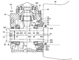
- FIG. 1 is a cross-sectional view showing a coupling structure between a hollow output shaft and a driven shaft according to an example of an embodiment of the present invention
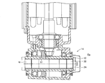
- FIG. 2 is an enlarged cross-sectional view taken along the line II-II in FIG. .
- the reduction gear 30 includes a bevel pinion 34 formed on the bevel pinion shaft 32 and a bevel gear 38 fixed to the hollow output shaft 36.
- the rotation of the motor (not shown) is transmitted to the hollow output shaft 36 while being decelerated through the meshing of the bevel pinion 34 and the bevel gear 38.
- the hollow output shaft 36 passes through the casing 40 of the speed reducer 30 and includes a hollow portion 42 that passes through the hollow output shaft 36.
- the driven shaft 46 of the counterpart machine 44 is inserted into the hollow portion 42.
- the “mating machine” is a machine that is driven by rotation of the hollow output shaft 36 of the speed reducer 30 such as a conveyor for transportation or an industrial machine tool, for example. Is a shaft directly rotated by the hollow output shaft 36, that is, an input shaft of the counterpart machine.
- the inner diameter D1 of the hollow output shaft 36 is slightly larger than the outer diameter d1 of the driven shaft 46, and both the shafts 36 and 46 have a clearance S2 (by clearance fitting). ) It is engaged.
- the hollow output shaft 36 and the driven shaft 46 are formed with key grooves 36A and 46A, respectively.
- a key 48 is fitted in a space P1 formed by the key grooves 36A and 46A, and the hollow output shaft 36 and the driven shaft 46 are connected via the key 48 so that power can be transmitted.
- the hollow output shaft 36 is formed with a plurality of communication passages 60 (four in this example, 60A to 60D) communicating the hollow portion 42 in the hollow output shaft 36 and the internal space 58 of the speed reducer 30.
- One of the communication passages 60 ⁇ / b> D opens in the bottom surface 36 ⁇ / b> A ⁇ b> 1 of the key groove 36 ⁇ / b> A of the hollow output shaft 36, thereby communicating the hollow portion 42 of the hollow output shaft 36 with the internal space 58 of the speed reducer 30.
- the hollow output shaft 36 and the driven shaft 46 are positioned (fixed) in the axial direction by passing through the positioning plate 50 disposed in the stepped portion 36 ⁇ / b> B of the hollow output shaft 36 and the positioning plate 50. This is done by a bolt 52 screwed into the driven shaft 46.
- the stepped portion 46B of the driven shaft 46 comes into contact with the end portion 36C on the counterpart machine side of the hollow output shaft 36, and the axial position of the driven shaft 46 is determined.
- a cover plate 54 is attached and fixed to the end 36D of the hollow output shaft 36 on the opposite machine side by bolts 56.
- the space including the gap S2 between the hollow output shaft 36 and the driven shaft 46 is a closed space as a common space Pc1.
- a specific configuration for making the common space Pc1 a closed space will be described.
- a casing 40 of the speed reducer 30 includes an input side casing 40A that rotatably supports the bevel pinion shaft 32, a main body casing 40B that covers substantially the entire hollow output shaft 36, and an opening 40B1 on the counterpart machine side of the main body casing 40B. It is mainly comprised by the other party casing 40C which obstruct
- the input side casing 40A is fixed and integrated with the main body casing 40B by bolts 62.
- the mating casing 40C is fixed and integrated with the main casing 40B by bolts 64.
- the hollow output shaft 36 is supported at both ends by a pair of tapered roller bearings 66A and 66B incorporated in the main body casing 40B and the counterpart casing 40C, respectively.
- a first O-ring (seal member) 68 is disposed between the input side casing 40A and the main body casing 40B.
- a second O-ring 70 is disposed between the main body casing 40B and the counterpart casing 40C.
- Two first oil seals (seal members) 72 are arranged in parallel on the opposite side of the axially opposite machine of the tapered roller bearing 66A between the main body casing 40B and the hollow output shaft 36.
- Two second oil seals (seal members) 74 are arranged in parallel on the axial counterpart machine side of the tapered roller bearing 66B between the counterpart casing 40C and the hollow output shaft 36.
- the stepped portion 46B of the driven shaft 46 is in contact with the end surface 36C on the counterpart machine side of the hollow output shaft 36, and the third O-ring 76 is disposed between the end surface 36C and the stepped portion 46B.
- the third O-ring 76 is provided between the inner periphery of the hollow output shaft 36 and the outer periphery of the driven shaft 46 (for example, a position indicated by a broken line and (76) in FIG. 1). May be.
- a fourth O-ring 78 is arranged between the hollow output shaft 36 and the cover plate 54 on the opposite machine side.
- the hollow output shaft 36 is formed with a communication path 60 (60A to 60D) that communicates the hollow portion 42 in the hollow output shaft 36 with the internal space 58 of the speed reducer 30, the internal space of the speed reducer 30 is formed.
- the lubricating oil sealed in 58 can enter the gap S2 between the hollow output shaft 36 and the driven shaft 46 via the communication path 60, and the gap S2 is lubricated.
- one of the communication passages 60D is opened in the bottom surface 36A1 of the key groove 36A of the hollow output shaft 36, so that the lubricating oil is also abundantly also around the key groove 36A (particularly susceptible to fretting). Can be supplied. Therefore, fretting is extremely unlikely to occur, and maintenance (to prevent fretting) specific to the connecting portion between the hollow output shaft 36 and the driven shaft 46 is unnecessary, and the lubricating oil in the speed reducer 30 is supplied at a predetermined time. Maintenance of the connecting part is also automatically achieved simply by replacing it with. Thereby, the frequency of maintenance can be greatly reduced.
- the four communication paths 60 are formed at the same position in the axial direction of the hollow output shaft 36.
- the movement of the lubricating oil in the gap S2 can be further promoted.
- by intentionally shifting the formation position (circumferential position and axial position) of the communication path 60 it is possible to further promote the movement of the lubricating oil in the gap S2, particularly in the axial direction. .
- the input side casing 40A, the main body casing 40B, and the mating side casing 40C constituting the casing 40 of the speed reducer 30 are sealed with each other by the first and second O-rings 68 and 70, respectively, and the lubricating oil from the common space Pc1 Prevents leakage.
- the main body casing 40B and the hollow output shaft 36 and between the counterpart casing 40C and the hollow output shaft 36 are sealed by two first and second oil seals 72 and 74, respectively.
- the stepped portion 46B of the driven shaft 46 is in contact with the end surface 36C of the hollow output shaft 36, and the end surface 36C of the hollow output shaft 36 on the counterpart machine side and the driven shaft 46 are in contact with each other.
- a third O-ring 76 is disposed between the stepped portion 46B.
- a fourth O-ring 78 is disposed between the hollow output shaft 36 and the cover plate 54 at the end of the hollow output shaft 36 on the opposite machine side.
- the common space Pc1 including the gap S2 between the hollow output shaft 36 and the driven shaft 46 forms a completely closed space (sealed space), and the hollow output shaft 36 and the driven shaft
- the lubricating oil that has entered the gap S ⁇ b> 2 with 46 does not leak to the outside (outside the speed reducer 30 or inside the counterpart machine 44).
- the driven shaft 46 of the counterpart machine 44 is inserted into the hollow portion 42 of the hollow output shaft 36 of the speed reducer 30 with a gap S2, and the lubricating oil in the speed reducer 30 is removed.
- the gap S2 between the hollow output shaft 36 and the driven shaft 46 including the periphery of the key 48 can be sufficiently lubricated, and the occurrence of fretting can be prevented.
- FIG. 3 shows an example of another embodiment.
- the third oil seal 80 is disposed between the driven shaft 46 of the counterpart machine 44 (the stepped portion 46A thereof).
- the fifth O-ring 82 is disposed between the mating end surface 40C1 of the mating casing 40C and the end surface 45A of the casing 45 of the mating machine 44 on the speed reducer side.
- the internal space 86 of the speed reducer 84 is partially expanded to the counterpart machine 44 side beyond the through hole 40C2 of the counterpart casing 40C of the speed reducer 84.
- the “internal space of the speed reducer” in the present invention includes a space continuously expanded to the outside of the casing in appearance as described above.
- the end 90C on the counterpart machine 44 side of the hollow output shaft 90 and the stepped portion 46B of the driven shaft 46 are in contact with each other, but are not sealed. Rather, the end 90C of the hollow output shaft 90 is positively provided with a plurality of grooves 90G along the radial direction (radial direction), and the grooves 90G function as “communication paths”.
- Lubricating oil is a gap between the hollow output shaft 90 and the driven shaft 46 from the internal space 86 of the speed reducer 84 via a groove 90G (as a communication path) formed in the end 90C of the hollow output shaft 90. You can enter S2.
- the lubricant can be sufficiently distributed in the vicinity of the end portion of the hollow output shaft 90 on the counterpart machine side (the first first point where the communication path 60 was formed only in the central portion in the axial direction). Fretting can be better prevented (as compared to the embodiment).
- FIG. 4 shows still another embodiment.
- the clearance S2 between the hollow output shaft 92 and the driven shaft 46 is different from the previous two embodiments in the way of closing the reducer 94 on the opposite machine side.
- a plate 96 that covers the end 92 ⁇ / b> E of the hollow output shaft 92 is provided on the opposite machine side of the casing 40.
- This plate 96 fulfills the function of the positioning plate 50 of the first and second embodiments. That is, the hollow output shaft 92 and the driven shaft 46 are positioned (fixed) in the axial direction by the plate 96 and the bolt 95 that passes through the plate 96 and is screwed into the driven shaft 46.
- a cover 98 that covers the end 92E of the hollow output shaft 92 is provided on the opposite machine side of the casing 40.
- a seventh O-ring (seal member) 99 is disposed between the cover 98 and the casing 40 (main body casing 40C).
- This configuration is such that the internal space 93 of the speed reducer 94 is continuously expanded beyond the through hole 40B1 of the main body casing 40B of the speed reducer 94 on the opposite machine side of the casing 40.
- the lubricating oil of the speed reducer 94 can enter the clearance S ⁇ b> 2 between the hollow output shaft 92 and the driven shaft 46 through the clearance S ⁇ b> 3 between the bolt hole 96 ⁇ / b> A of the plate 96 and the bolt 95. That is, in this embodiment, the bolt hole 96A of the plate 96 functions as a “communication path”.
- a groove 92H is further formed along the radial direction on the end surface 92C of the hollow output shaft 92, and this groove 92H also functions as a “communication path” according to the present invention.
- the third embodiment it is possible to more effectively prevent fretting in the vicinity of the end portion on the opposite side of the machine opposite to the hollow output shaft 92 as compared with the second embodiment, as a result.
- a good lubricating action can be obtained over the entire axial direction of the hollow output shaft 92, and fretting can be prevented almost completely.
- the hollow output shaft and the driven shaft are connected by the “key”.
- the connection between the hollow output shaft and the driven shaft in the present invention has a gap.
- Applicable to any connections that have. Examples of other connections having gaps include spline connection that can withstand higher loads, and so-called D-cut connection known as a simpler structure (the cross section of the hollow output shaft and the driven shaft is the letter “D”). Shaped connection).
- a key groove is formed on both the hollow output shaft and the driven shaft, and a key that engages with each key groove is fitted (with a gap fit).
- either the hollow output shaft or the driven shaft and the key are integrally formed, and the key integrated with the one shaft is fitted into the key groove of the other shaft.
- the integration of one shaft and the key may be integrally formed or cut as one member from the beginning, and the two members are integrated with no gap by shrink fitting or press fitting. It may be allowed.
- the key is integrated on the hollow output shaft side, the method of making the key separately is often easier to manufacture.
- the structure which opens a communicating path in the bottom face of a keyway is effective in any case.
- the communication path is opened on the bottom surface of the key groove of the hollow output shaft as in the previous embodiment. It is good to form so as to.
- the key groove exists only on the driven shaft side (when the key is integrated with the hollow output shaft)
- the communication path is made to penetrate the integrated key portion of the hollow output shaft.
- it may be formed so as to open to the bottom surface of the keyway of the driven shaft. In this way, the method of integrating one of the shafts and the key can realize fretting prevention more reliably because fretting around the key occurs only between the shaft on the other side.
- the “common space including the gap between the hollow output shaft and the driven shaft” according to the present invention is only required to be a closed space as a whole.
- the structure for that is not necessarily limited to the structure mentioned above.
- the structure on the counterpart machine side in FIG. 1 and the structure on the counter machine side in FIG. 4 may be combined.
- a configuration in which the opposite machine side of the hollow output shaft itself is closed is adopted. May be. In this case, since the gap between the hollow output shaft and the driven shaft is originally closed on the opposite machine side, a special configuration for closing the gap is not particularly necessary.
- the groove of the O-ring is formed on the driven shaft, but the groove of the O-ring may be formed on either side of the members in contact with each other, for example, the end face of the hollow output shaft Alternatively, an O-ring groove may be formed on the inner periphery.
- the seal member is not necessarily limited to only an O-ring or an oil seal. For example, liquid packing, solid packing, or the like may be employed.
- the hollow output shaft does not necessarily have to penetrate on the opposite machine side of the casing.
- the gap between the hollow output shaft and the driven shaft is included in the internal space of the reducer as a result.
- a special configuration for closing the gap is unnecessary.
- the way of forming the communication passage and the number of the formation are not limited to the above configuration example as long as the hollow portion in the hollow output shaft communicates with the internal space of the reduction gear. .
- the present invention can be used for a connection structure between a hollow output shaft and a driven shaft inserted into a hollow portion of the hollow output shaft, or a speed reducer having the connection structure.
- Japan Application No. 2010-44585 filed on Mar. 1, 2010 is incorporated herein by reference in its entirety.
Landscapes
- Engineering & Computer Science (AREA)
- General Engineering & Computer Science (AREA)
- Mechanical Engineering (AREA)
- General Details Of Gearings (AREA)
Abstract
Description
36…ホロー出力軸
40…ケーシング
40A…入力側ケーシング
40B…本体ケーシング
40C…相手側ケーシング
42…中空部
44…相手機械
46…被駆動軸
48…キー
58…内部空間
60(69A~60D)…連通路
S2…隙間
Pc1…共通空間
Claims (10)
- 中空部を有するホロー出力軸を備えた減速機における当該ホロー出力軸と、該ホロー出力軸の前記中空部に挿入される相手機械の被駆動軸との連結構造であって、
前記ホロー出力軸内の前記中空部と前記減速機の内部空間とを連通する連通路を備え、且つ、
前記ホロー出力軸と前記被駆動軸との間の隙間を含む空間が、閉じた空間とされている
ことを特徴とするホロー出力軸と被駆動軸との連結構造。 - 請求項1において、
前記ホロー出力軸と前記被駆動軸との間にシール部材が配置されている
ことを特徴とするホロー出力軸と被駆動軸との連結構造。 - 請求項2において、
前記ホロー出力軸の端面と被駆動軸との間にシール部材が配置されている
ことを特徴とするホロー出力軸と被駆動軸との連結構造。 - 請求項1~3のいずれかにおいて、
前記ホロー出力軸と前記被駆動軸との間の隙間が、前記減速機の反相手機械側の外部空間に対して閉じている
ことを特徴とするホロー出力軸と被駆動軸との連結構造。 - 請求項4において、
前記中空部が前記ホロー出力軸を貫通し、
該ホロー出力軸が前記減速機のケーシングを貫通し、
該ケーシングの反相手機械側に、該ホロー出力軸の端部を覆うカバーが設けられ、且つ
該カバーと前記ケーシングとの間にシール部材が配置されている
ことを特徴とするホロー出力軸と被駆動軸との連結構造。 - 請求項4において、
前記ホロー出力軸自体の反相手機械側が閉じた構造とされている
ことを特徴とするホロー出力軸と被駆動軸との連結構造。 - 請求項1~6のいずれかにおいて、
前記ホロー出力軸と前記被駆動軸とが、該ホロー出力軸と前記被駆動軸の少なくとも一方の軸に形成したキー溝に嵌入されたキーを介して動力伝達可能に連結されており、
上記連通路が前記キー溝の底面に開口することによって前記中空部と前記減速機の内部空間とを連通している
ことを特徴とするホロー出力軸と被駆動軸との連結構造。 - 中空部を有するホロー出力軸を備え、該中空部に相手機械の被駆動軸が挿入される減速機において、
前記ホロー出力軸内の前記中空部と前記減速機の内部空間とを連通する連通路を備えた
ことを特徴とする減速機。 - 請求項8において、
前記ホロー出力軸自体に上記連通路が形成されている
ことを特徴とする減速機。 - 請求項8または9において、
前記ホロー出力軸に、Oリングを配置するための溝が形成されている
ことを特徴とする減速機。
Priority Applications (3)
| Application Number | Priority Date | Filing Date | Title |
|---|---|---|---|
| DE112011100746T DE112011100746T5 (de) | 2010-03-01 | 2011-01-31 | Verbindungsstruktur zwischen hohler abtriebswelle und angetriebener welle und drehzahluntersetzungsgetriebe |
| CN201180011907.2A CN102782371B (zh) | 2010-03-01 | 2011-01-31 | 空心输出轴与被驱动轴的连结结构及减速机 |
| US13/601,173 US9062753B2 (en) | 2010-03-01 | 2012-08-31 | Connection structure between hollow output shaft and driven shaft, and speed reducer |
Applications Claiming Priority (2)
| Application Number | Priority Date | Filing Date | Title |
|---|---|---|---|
| JP2010-044585 | 2010-03-01 | ||
| JP2010044585A JP5315266B2 (ja) | 2010-03-01 | 2010-03-01 | ホロー出力軸と被駆動軸との連結構造、及び減速機 |
Related Child Applications (1)
| Application Number | Title | Priority Date | Filing Date |
|---|---|---|---|
| US13/601,173 Continuation US9062753B2 (en) | 2010-03-01 | 2012-08-31 | Connection structure between hollow output shaft and driven shaft, and speed reducer |
Publications (1)
| Publication Number | Publication Date |
|---|---|
| WO2011108320A1 true WO2011108320A1 (ja) | 2011-09-09 |
Family
ID=44541988
Family Applications (1)
| Application Number | Title | Priority Date | Filing Date |
|---|---|---|---|
| PCT/JP2011/051857 Ceased WO2011108320A1 (ja) | 2010-03-01 | 2011-01-31 | ホロー出力軸と被駆動軸との連結構造、及び減速機 |
Country Status (5)
| Country | Link |
|---|---|
| US (1) | US9062753B2 (ja) |
| JP (1) | JP5315266B2 (ja) |
| CN (1) | CN102782371B (ja) |
| DE (1) | DE112011100746T5 (ja) |
| WO (1) | WO2011108320A1 (ja) |
Families Citing this family (6)
| Publication number | Priority date | Publication date | Assignee | Title |
|---|---|---|---|---|
| JP5315266B2 (ja) * | 2010-03-01 | 2013-10-16 | 住友重機械工業株式会社 | ホロー出力軸と被駆動軸との連結構造、及び減速機 |
| JP6096487B2 (ja) * | 2012-11-29 | 2017-03-15 | 住友重機械工業株式会社 | 軸の連結構造 |
| JP6193598B2 (ja) * | 2013-03-29 | 2017-09-06 | 住友重機械工業株式会社 | 軸の連結構造 |
| CN104165209A (zh) * | 2014-06-16 | 2014-11-26 | 南京宁嘉机电有限公司 | 石油钻井转盘用齿轮箱 |
| CN107461478B (zh) * | 2017-08-14 | 2023-12-22 | 江苏省金象传动设备股份有限公司 | 一种立磨机减速器输入轴支撑结构 |
| CN108975190A (zh) * | 2018-09-26 | 2018-12-11 | 东莞市台冠起重机械设备有限公司 | 一种用于起升机构的减速器与卷筒的连接装置 |
Citations (3)
| Publication number | Priority date | Publication date | Assignee | Title |
|---|---|---|---|---|
| JPH0266723U (ja) * | 1988-11-02 | 1990-05-21 | ||
| JPH03244859A (ja) * | 1989-09-21 | 1991-10-31 | Dana Corp | 変速機レインジ・ボックス用出力アセンブリ |
| JP2006200747A (ja) * | 2006-02-20 | 2006-08-03 | Sumitomo Heavy Ind Ltd | ギヤドモータ用の減速機、ギヤドモータ及びそのシリーズ |
Family Cites Families (40)
| Publication number | Priority date | Publication date | Assignee | Title |
|---|---|---|---|---|
| US292994A (en) * | 1884-02-05 | Fenn eb i | ||
| US2072090A (en) * | 1935-10-10 | 1937-03-02 | Borg Warner | Double universal joint assembly |
| US2090066A (en) * | 1935-10-17 | 1937-08-17 | Carl D Peterson | Lubricating means for drive mechanism |
| US2116290A (en) * | 1936-09-10 | 1938-05-03 | Spicer Mfg Corp | Sealed propeller shaft |
| US2543918A (en) * | 1945-10-08 | 1951-03-06 | Dodge Mfg Corp | Shaft coupling |
| US2672115A (en) * | 1951-04-28 | 1954-03-16 | Outboard Marine & Mfg Co | Dual propeller propulsion device |
| US2841966A (en) * | 1955-11-14 | 1958-07-08 | Charles W Belden | Flexible couplings |
| US3133452A (en) * | 1961-07-21 | 1964-05-19 | Gen Electric | Drive mechanism |
| US3757535A (en) * | 1971-11-03 | 1973-09-11 | Avco Corp | Drive assembly with compensation for misalignment |
| US3802294A (en) * | 1972-09-28 | 1974-04-09 | Borg Warner | Automotive transmission |
| US3993227A (en) * | 1975-09-08 | 1976-11-23 | Esco Corporation | Rotary feeder valve |
| US4176564A (en) * | 1976-01-29 | 1979-12-04 | S.R.M. Hydromekanik Aktiebolg | Control arrangement for variable power transmission |
| US4232772A (en) * | 1978-01-05 | 1980-11-11 | General Electric Company | Electromagnetically controlled, resettable high-speed shaft disconnect |
| US4341296A (en) * | 1980-09-22 | 1982-07-27 | United Technologies Corporation | Flow divider for liquid coolant or lubricant |
| SE440388B (sv) * | 1983-11-22 | 1985-07-29 | Flygt Ab | Hylsforband |
| JPH063204Y2 (ja) * | 1987-03-30 | 1994-01-26 | トヨタ自動車株式会社 | 歯車変速機の潤滑機構 |
| US4904214A (en) * | 1989-03-13 | 1990-02-27 | Brunswick Corporation | Marine stern drive with lubricated and sealed output coupler |
| US5207697A (en) * | 1991-06-27 | 1993-05-04 | Stryker Corporation | Battery powered surgical handpiece |
| US5119905A (en) * | 1991-10-28 | 1992-06-09 | General Motors Corporation | Accessory drive spline lubrication system for a turbine engine reduction gear box |
| JP2866247B2 (ja) * | 1992-02-25 | 1999-03-08 | 住友重機械工業株式会社 | モータ付直交歯車減速機のシリーズ及びシリーズ群 |
| FR2699229B1 (fr) * | 1992-12-11 | 1995-03-10 | Poclain Hydraulics Sa | Groupe moteur hydraulique d'entraînement d'un outil de forage. |
| US5366399A (en) * | 1993-12-13 | 1994-11-22 | Brunswick Corporation | Marine stern drive with lubricated and semi-sealed engine output coupler |
| US5857913A (en) * | 1995-09-06 | 1999-01-12 | Tsubakimoto Emerson Co. | Hollow shaft reduction gear with overload protecting device |
| US6098753A (en) * | 1998-06-05 | 2000-08-08 | Pratt & Whitney Canada Corp. | System for delivering pressurized lubricant fluids to an interior of a rotating hollow shaft |
| JP2003113908A (ja) | 2001-10-05 | 2003-04-18 | Sumitomo Heavy Ind Ltd | 直交減速装置 |
| JP2004121989A (ja) * | 2002-10-02 | 2004-04-22 | Nachi Fujikoshi Corp | 屎尿攪拌装置。 |
| DE10248355A1 (de) * | 2002-10-17 | 2004-04-29 | Ina-Schaeffler Kg | Nockenwellenversteller mit elektrischem Antrieb |
| JP4141245B2 (ja) * | 2002-12-20 | 2008-08-27 | 住友重機械工業株式会社 | ハイポイド減速装置及びそのシリーズ |
| JP2007078033A (ja) * | 2005-09-12 | 2007-03-29 | Aisin Ai Co Ltd | 動力伝達装置 |
| DE102005059840A1 (de) * | 2005-12-15 | 2007-06-28 | Schaeffler Kg | Nockenwellenversteller |
| CN101375385B (zh) * | 2006-01-13 | 2012-05-30 | 纳博特斯克株式会社 | 包括冷却循环路径的基板搬运机器人的驱动设备 |
| DE102006007584A1 (de) * | 2006-02-18 | 2007-08-30 | Schaeffler Kg | Nockenwellenversteller mit einem Überlagerungsgetriebe |
| JP2009156354A (ja) * | 2007-12-27 | 2009-07-16 | Jtekt Corp | ボールねじ装置 |
| JP5202985B2 (ja) * | 2008-02-19 | 2013-06-05 | 住友重機械工業株式会社 | 減速機 |
| JP4859893B2 (ja) | 2008-08-12 | 2012-01-25 | ヤフー株式会社 | 広告配信装置、広告配信方法、及び広告配信制御プログラム |
| JP5130177B2 (ja) * | 2008-09-29 | 2013-01-30 | 住友重機械工業株式会社 | 減速装置 |
| JP2010091013A (ja) * | 2008-10-08 | 2010-04-22 | Sumitomo Heavy Ind Ltd | 減速装置の軸の支持構造 |
| US7832189B1 (en) * | 2009-11-11 | 2010-11-16 | Cnh America Llc | Apparatus to improve modular cutterbar connecting shaft spline durability |
| US8356695B2 (en) * | 2009-11-17 | 2013-01-22 | Cnh America Llc | Method and apparatus for oiling splines in a bevel gearbox |
| JP5315266B2 (ja) * | 2010-03-01 | 2013-10-16 | 住友重機械工業株式会社 | ホロー出力軸と被駆動軸との連結構造、及び減速機 |
-
2010
- 2010-03-01 JP JP2010044585A patent/JP5315266B2/ja not_active Expired - Fee Related
-
2011
- 2011-01-31 WO PCT/JP2011/051857 patent/WO2011108320A1/ja not_active Ceased
- 2011-01-31 CN CN201180011907.2A patent/CN102782371B/zh not_active Expired - Fee Related
- 2011-01-31 DE DE112011100746T patent/DE112011100746T5/de active Pending
-
2012
- 2012-08-31 US US13/601,173 patent/US9062753B2/en not_active Expired - Fee Related
Patent Citations (3)
| Publication number | Priority date | Publication date | Assignee | Title |
|---|---|---|---|---|
| JPH0266723U (ja) * | 1988-11-02 | 1990-05-21 | ||
| JPH03244859A (ja) * | 1989-09-21 | 1991-10-31 | Dana Corp | 変速機レインジ・ボックス用出力アセンブリ |
| JP2006200747A (ja) * | 2006-02-20 | 2006-08-03 | Sumitomo Heavy Ind Ltd | ギヤドモータ用の減速機、ギヤドモータ及びそのシリーズ |
Also Published As
| Publication number | Publication date |
|---|---|
| DE112011100746T5 (de) | 2013-01-31 |
| US9062753B2 (en) | 2015-06-23 |
| CN102782371B (zh) | 2015-06-03 |
| JP2011179595A (ja) | 2011-09-15 |
| JP5315266B2 (ja) | 2013-10-16 |
| US20130058709A1 (en) | 2013-03-07 |
| CN102782371A (zh) | 2012-11-14 |
Similar Documents
| Publication | Publication Date | Title |
|---|---|---|
| JP5315266B2 (ja) | ホロー出力軸と被駆動軸との連結構造、及び減速機 | |
| US8353797B2 (en) | Lubrication system for a planetary gear set | |
| JP6893976B2 (ja) | モータと減速機とが連結された入力軸構造 | |
| US20060025271A1 (en) | Reducer with internally meshing planetary gear mechanism and device incorporating the reducer | |
| US10443697B2 (en) | Speed reduction gear comprising two intermediate transmission lines | |
| US20150219199A1 (en) | Differential device and method of assembling the same | |
| CN107642591B (zh) | 齿轮部件的支承部润滑结构以及差动装置 | |
| US20060035746A1 (en) | Drive shaft assembly and method of separation | |
| JP5157237B2 (ja) | ギアカップリングの潤滑剤交換方法 | |
| JP3751488B2 (ja) | Ff車両用変速機の差動装置 | |
| WO2018096941A1 (ja) | トロイダル無段変速機 | |
| JP5035164B2 (ja) | ディファレンシャル装置 | |
| JP5038208B2 (ja) | トランスミッションにおける潤滑構造 | |
| JP5051040B2 (ja) | ディファレンシャル装置 | |
| JPH08159170A (ja) | 同期噛合装置の潤滑構造 | |
| JP6489154B2 (ja) | 直結型モータポンプ | |
| JP4819109B2 (ja) | モータ軸とホロー軸との連結構造及び連結方法 | |
| JP2009008114A (ja) | 歯車形軸継手の給脂機構 | |
| JP2007100880A (ja) | 変速機における潤滑油受け渡し構造 | |
| JPH03199685A (ja) | 流体ポンプ装置 | |
| US20250137522A1 (en) | Oil guiding component for an oil guiding arrangement | |
| CN214248228U (zh) | 驱动桥主传动总成及托架组件和工程机械 | |
| US20040251107A1 (en) | Clutch housing with multi-function hydraulic sleeve | |
| CN110816263A (zh) | 一种车辆、动力系统及其取力器 | |
| CN213511982U (zh) | 一种高扭矩减速机及矿山专用运载装置 |
Legal Events
| Date | Code | Title | Description |
|---|---|---|---|
| WWE | Wipo information: entry into national phase |
Ref document number: 201180011907.2 Country of ref document: CN |
|
| 121 | Ep: the epo has been informed by wipo that ep was designated in this application |
Ref document number: 11750433 Country of ref document: EP Kind code of ref document: A1 |
|
| WWE | Wipo information: entry into national phase |
Ref document number: 1120111007469 Country of ref document: DE Ref document number: 112011100746 Country of ref document: DE |
|
| 122 | Ep: pct application non-entry in european phase |
Ref document number: 11750433 Country of ref document: EP Kind code of ref document: A1 |