WO2011108243A1 - クランプ - Google Patents
クランプ Download PDFInfo
- Publication number
- WO2011108243A1 WO2011108243A1 PCT/JP2011/001140 JP2011001140W WO2011108243A1 WO 2011108243 A1 WO2011108243 A1 WO 2011108243A1 JP 2011001140 W JP2011001140 W JP 2011001140W WO 2011108243 A1 WO2011108243 A1 WO 2011108243A1
- Authority
- WO
- WIPO (PCT)
- Prior art keywords
- hole
- tubular body
- pipe
- pin
- clamp
- Prior art date
- Legal status (The legal status is an assumption and is not a legal conclusion. Google has not performed a legal analysis and makes no representation as to the accuracy of the status listed.)
- Ceased
Links
Images






Classifications
-
- F—MECHANICAL ENGINEERING; LIGHTING; HEATING; WEAPONS; BLASTING
- F16—ENGINEERING ELEMENTS AND UNITS; GENERAL MEASURES FOR PRODUCING AND MAINTAINING EFFECTIVE FUNCTIONING OF MACHINES OR INSTALLATIONS; THERMAL INSULATION IN GENERAL
- F16L—PIPES; JOINTS OR FITTINGS FOR PIPES; SUPPORTS FOR PIPES, CABLES OR PROTECTIVE TUBING; MEANS FOR THERMAL INSULATION IN GENERAL
- F16L3/00—Supports for pipes, cables or protective tubing, e.g. hangers, holders, clamps, cleats, clips, brackets
- F16L3/22—Supports for pipes, cables or protective tubing, e.g. hangers, holders, clamps, cleats, clips, brackets specially adapted for supporting a number of parallel pipes at intervals
- F16L3/223—Supports for pipes, cables or protective tubing, e.g. hangers, holders, clamps, cleats, clips, brackets specially adapted for supporting a number of parallel pipes at intervals each support having one transverse base for supporting the pipes
- F16L3/2235—Supports for pipes, cables or protective tubing, e.g. hangers, holders, clamps, cleats, clips, brackets specially adapted for supporting a number of parallel pipes at intervals each support having one transverse base for supporting the pipes each pipe being supported by a common element fastened to the base
-
- B—PERFORMING OPERATIONS; TRANSPORTING
- B60—VEHICLES IN GENERAL
- B60R—VEHICLES, VEHICLE FITTINGS, OR VEHICLE PARTS, NOT OTHERWISE PROVIDED FOR
- B60R16/00—Electric or fluid circuits specially adapted for vehicles and not otherwise provided for; Arrangement of elements of electric or fluid circuits specially adapted for vehicles and not otherwise provided for
- B60R16/02—Electric or fluid circuits specially adapted for vehicles and not otherwise provided for; Arrangement of elements of electric or fluid circuits specially adapted for vehicles and not otherwise provided for electric constitutive elements
- B60R16/0207—Wire harnesses
- B60R16/0215—Protecting, fastening and routing means therefor
-
- F—MECHANICAL ENGINEERING; LIGHTING; HEATING; WEAPONS; BLASTING
- F16—ENGINEERING ELEMENTS AND UNITS; GENERAL MEASURES FOR PRODUCING AND MAINTAINING EFFECTIVE FUNCTIONING OF MACHINES OR INSTALLATIONS; THERMAL INSULATION IN GENERAL
- F16L—PIPES; JOINTS OR FITTINGS FOR PIPES; SUPPORTS FOR PIPES, CABLES OR PROTECTIVE TUBING; MEANS FOR THERMAL INSULATION IN GENERAL
- F16L3/00—Supports for pipes, cables or protective tubing, e.g. hangers, holders, clamps, cleats, clips, brackets
- F16L3/22—Supports for pipes, cables or protective tubing, e.g. hangers, holders, clamps, cleats, clips, brackets specially adapted for supporting a number of parallel pipes at intervals
- F16L3/237—Supports for pipes, cables or protective tubing, e.g. hangers, holders, clamps, cleats, clips, brackets specially adapted for supporting a number of parallel pipes at intervals for two pipes
Definitions
- the present invention relates to a clamp, and more particularly to a pipe clamp for attaching a filler pipe or the like to a vehicle body panel.
- a clamp for attaching a tubular body such as a filler pipe to a support member such as a vehicle body panel in which a locking hole is formed a first part attached to the support member and a first part rotatably provided on the first part
- a tubular body is sandwiched between a first part and a second part
- the first portion has a grommet portion that expands and engages with the locking hole when the screw is screwed.
- the second portion includes a through hole in a portion corresponding to the grommet portion in a state where the tubular body is sandwiched between the second portion and the first portion.
- the screw passes through the through hole and is inserted into the grommet portion with the second portion sandwiching the tubular body between the second portion and the first portion.
- the clamp according to Patent Document 1 requires a screw that is separate from the first member and the second member, which increases the number of parts and makes the installation work complicated. Moreover, since a clamp cannot complete a coupling
- the present invention has been made in view of the above background, and an object thereof is to provide a clamp that can be easily attached.
- the present invention provides a clamp (10) for attaching a tubular body (200, 201) to a support member (205) in which a locking hole (206) is formed.
- a first member through-hole (25) is formed at a position corresponding to the locking hole and is disposed on the surface of the member, and protrudes from a peripheral portion on the support member side of the first member through-hole.
- a member through hole (86) is formed.
- the present invention is also a clamp (300) for attaching the tubular body (200, 201) to the support member (205) in which the locking hole (206) is formed, and is disposed on the surface of the support member.
- the second member through-hole (25) is formed in a portion corresponding to the first member through-hole while being stopped and in the closed position, and the peripheral portion of the second member through-hole on the support member side Projecting from the first member through hole and into the locking hole
- a second member (12) having a plurality of flexible leg pieces (16) capable of being inserted, and being held in the second member through-hole and being displaced toward the distal end side of the leg pieces.
- the second member includes a boss portion (302) at an end portion of the second member through hole on the support member side, and the boss portion passes through the first member through hole. The protruding end can be brought into contact with the peripheral edge portion of the locking hole, and the leg piece can be protruded radially inward of the protruding end of the boss portion and can enter the locking hole. It is characterized by becoming.
- the clamp is provided as an assembly in which the base member, the lid member, and the pin member are integrally assembled, workability when attaching the tubular body to the support member is good. Further, the coupling between the clamp and the tubular body and the coupling between the clamp and the support member can be performed independently.
- two tubular body holding portions are provided so as to sandwich the first member through-hole as viewed from the axial direction of the first member through-hole.
- This configuration improves the mounting stability of the tubular body with respect to the support member.
- the clamp is configured as one assembly, it is possible to facilitate the attachment work of the tubular body to the support member.
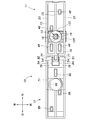
- the disassembled perspective view which shows the pipe clamp which concerns on 1st Embodiment.
- the perspective view which shows the pipe clamp which concerns on 1st Embodiment.
- the bottom view which shows the pipe clamp which concerns on 1st Embodiment IV-IV sectional view of Fig. 2
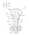
- the perspective view which shows the pin member which concerns on 1st Embodiment.
- the perspective view which shows the pin hole of the base member which concerns on 1st Embodiment.
- the perspective view which looked at the hinge part of the pipe clamp concerning a 1st embodiment from the lower part (state where a lid member opened to a base member)
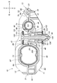
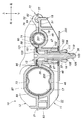
- the perspective view which shows the attachment structure of the filler pipe and breather pipe to the vehicle body panel using the pipe clamp which concerns on 1st Embodiment.
- a pipe clamp (clamp) 10 includes a base member (first member) 11 made of a resin material and a lid member (first member) rotatably supported by the base member 11. 2 member) 12 and a pin member 13 held by the base member 11 as main components.
- the pipe clamp 10 sandwiches a filler pipe 200 and a breather pipe 201, which are tubular bodies, between the base member 11 and the lid member 12, and the base member 11 is attached to the surface of the vehicle body panel 205 as a support member.
- the pipe 200 and the breather pipe 201 are fixed to the vehicle body panel 205.
- the base member 11 includes a main body portion 15 extending in the left-right direction, a leg piece portion 16 projecting downward from a lower portion of the main body portion 15, and an upper portion of the main body portion 15. Formed on the upper portion of the main body 15 as an engagement portion between the lid member 12 and the first and second pipe holding portions 17 and 18 that are recessed in the hinge, the hinge shaft portion 19 provided at the left end portion of the main body portion 15, and the lid member 12.
- the two connecting holes 20 and the four connecting claws 21 are provided.
- a plurality of meat stealing portions 22 that open downward are recessed in the lower portion of the main body portion 15, and a plurality of ribs 23 are formed so as to partition each meat stealing portion 22.
- the lower ends of the ribs 23 are arranged on a virtual plane that is substantially flush with each other, and the main body portion 15 can come into contact with a flat plane (plate material or the like) at the lower portion.
- a pin hole (first member through hole) 25 extending in the vertical direction and communicating with the upper surface and the lower surface of the main body portion is formed in an intermediate portion in the left-right direction of the main body portion 15.
- the pin hole 25 has a circular cross section, the upper half portion 26 is coaxially expanded with respect to the lower half portion 27, and an annular step facing upward at the boundary portion.
- a portion 28 is formed.
- the step portion 28 is provided with four guide convex portions 30 projecting upward on the bottom surface 29 facing upward at equal intervals (90 ° intervals) in the circumferential direction.
- Each guide convex portion 30 is parallel to the bottom surface 29 from the upper surface of the inclined surface 31 and the inclined surface 31 protruding upward from the bottom surface 29 as it proceeds in the counterclockwise direction in the circumferential direction of the pin hole 25 as viewed from above.
- an upper surface 32 extending in the counterclockwise direction in the circumferential direction.
- An end portion of the upper surface different from the inclined surface 31 side is continuous with the bottom surface 29 through a vertical plane.
- a boss portion 34 protruding upward from the upper surface of the base member 11 is formed at the upper end portion of the pin hole 25.
- An annular groove-shaped meat stealing portion 35 is formed on the peripheral edge portion of the lower end portion of the pin hole 25 so as to surround the pin hole 25 coaxially.
- Each leg piece 16 projects downward from the inner peripheral portion of the portion where the meat stealing portion 35 is formed in the peripheral portion of the lower end portion of the pin hole 25 in the circumferential direction of the pin hole 25. It is formed at equal intervals along.
- Each leg piece 16 functions as a grommet inserted into a locking hole 206 formed in the vehicle body panel 205. Projections with inclined surfaces facing diagonally upward so as to project toward the central axis side of the pin hole 25 toward the tip (lower end) at the portion of each leg piece 16 facing the central axis side of the pin hole 25 37 is formed, and a claw portion 38 that protrudes toward the central axis of the pin hole 25 is formed on each protrusion 37.
- Each claw part 38 is provided with a check surface facing downward at its lower part.
- Each leg piece portion 16 is flexible and can be tilted in the radial direction of the pin hole 25.
- a first pipe holding part (tubular body holding part) 17 is provided on the right side of the pin hole 25 on the upper surface of the base member 11, and a second pipe holding part (tubular body holding part) 18 is provided on the left side. .
- the first pipe holding part 17 and the second pipe holding part 18 have a groove shape, extend in the front-rear direction, and continue to the front surface and the rear surface of the base member 11.
- the first pipe holding portion 17 has a flat semicircular cross section so as to correspond to an outer surface of a filler pipe 200 described later.
- the second pipe holding portion 18 has a substantially semicircular cross section so as to correspond to an outer surface of a breather pipe 201 described later.
- first pipe holding part 17 and the second pipe holding part 18 On the surfaces of the first pipe holding part 17 and the second pipe holding part 18, ridges 46 and 47 extending in the left-right direction are formed. Further, the surface of the first pipe holding part 17 and the second pipe holding part 18 is cut out by a U-shaped slit communicating with the meat stealing part 22, and the first pipe holding part 17 or the second pipe is formed at the tip part thereof. Pressing pieces 48 and 49 having convex portions protruding inward (upward) of the pipe holding portion 18 are formed. The pressing pieces 48 and 49 have flexibility and can be tilted. The protrusions 46 and 47 and the pressing pieces 48 and 49 are provided for the purpose of improving the adhesion with the filler pipe 200 and the breather pipe 201.
- the hinge shaft portion 19 includes a shaft support portion 51 that protrudes leftward from the left end surface of the main body portion 15, and a columnar hinge shaft 52 that protrudes forward and rearward from the distal end portion of the shaft support portion 51.
- the shaft support portion 51 is formed to have a substantially rectangular shape when viewed from above or below, and the front surface and the rear surface of the shaft support portion 51 extend parallel to each other in the left-right direction (see FIG. 3).
- convex portions 54, 54 that protrude forward or rearward and extend in the vertical direction are formed at portions located below the hinge shafts 52.
- connection holes 20 and 20 are formed such that the opening portion at the upper end is narrower than the inside. That is, the connection holes 20 and 20 have a locking portion at the upper end opening.
- the insides of the connection holes 20 and 20 communicate with the front surface or the rear surface of the base member 11 through the work openings 57 and 57.
- a recess 56 that is recessed downward from the top surface is formed at the upper right end of the main body 15.
- four connecting claws 21 are arranged in pairs.
- Each connecting claw 21 has a flexible protrusion piece extending upward from the bottom of the recess 56 and a claw portion having a downward check surface provided at the tip of the protrusion piece.
- the paired connecting claws 21 are arranged so that the claws are opposed to each other. Further, the two pairs of connecting claws 21 that are paired are disposed on the front side and the rear side of the recess 56 so as to be separated from each other.
- the lid member 12 is provided with a body portion 71 extending in the left-right direction, a hinge bearing portion 72 formed at the right end portion of the body portion 71, and a recess provided in the upper portion of the body portion 71.
- the third and fourth pipe holding portions 73 and 74, and two connecting pieces 75 and two connecting claws 76 formed on the upper portion of the main body 71 as engaging portions with the base member 11 are provided.
- the hinge bearing portion 72 is provided at the front fork portion 78 and the rear fork portion 79 that protrude from the right end portion of the main body portion 71 in the front-rear direction to the right and the protruding end portions of the fork portions 78 and 79.
- Bearing parts 81 and 82 are provided.
- the bearing portions 81 and 82 are arranged so that the axes thereof extend in the front-rear direction and are coaxial.
- the front end portion or the rear end portion of the hinge shaft 52 is loosely fitted to the bearing portions 81 and 82.
- the distance in the front-rear direction between the bearing portions 81 and 82 is shorter than the length in the front-rear direction of the hinge shaft 52 so that the hinge shaft 52 cannot be detached from the bearing portions 81 and 82.
- Such a positional relationship between the hinge shaft 52 and the bearing portions 81 and 82 is established by molding the base member 11 and the lid member 12 simultaneously. In this way, the lid member 12 is rotatably supported by the base member 11 via the hinge portion including the bearing portions 81 and 82 and the hinge shaft 52.
- convex portions 77 and 77 projecting in directions close to each other are formed at portions of the bearing portions 81 and 82 facing each other. The distance between the front and rear of both bearing portions 81 and 82 is set larger than the front and rear length of the shaft support portion 51, and the lid member 12 is open with respect to the base member 11 (the state shown in FIGS. 1 to 7).
- the lid member 12 In a state where the lid member 12 is located on the left side of the base member 11, the lid member 12 has play in the front-rear direction with respect to the base member 11.
- the convex portions 77 and 78 and the convex portions 54 and 54 reduce play between the shaft support portion 51 and the bearing portions 81 and 82 in a state where the lid member is open with respect to the base member.
- a circular access hole (second member through-hole) 86 penetrating in the vertical direction is formed in a substantially central portion in the left-right direction of the upper portion of the main body 71.
- the access hole 86 is coaxial with the pin hole 25 in a state where the lid member 12 is closed with respect to the base member 11 (the state shown in FIGS. 8 to 10, a state where the lid member 12 is located above the base member 11). It is arranged to be. Further, the diameter of the access hole 86 is formed larger than the outer diameter of the boss portion 34.
- the third pipe holding part 73 is recessed on the left side of the access hole 86 in the upper part of the main body 71, and the fourth pipe holding part 74 is provided on the right side.
- the third pipe holding portion 73 and the fourth pipe holding portion 74 have a groove shape, extend in the front-rear direction, and continue to the front surface and the rear surface of the lid member 12.
- the cross section of the third pipe holding portion 73 is formed in a flat semicircular shape so as to correspond to the outer surface of the filler pipe 200 described later.
- the fourth pipe holding portion 74 has a substantially semicircular cross section so as to correspond to an outer surface of a breather pipe 201 described later. In a state where the lid member 12 is closed with respect to the base member 11, the third pipe holding portion 73 faces the first pipe holding portion 17, and the fourth pipe holding portion 74 faces the second pipe holding portion 18.
- ridges 87 and 88 extending in the left-right direction are formed on the surfaces of the third pipe holding portion 73 and the fourth pipe holding portion 74. Further, the surface of the third pipe holding portion 73 and the fourth pipe holding portion 74 is cut out by a U-shaped slit that communicates with the lower portion of the main body portion 71, and the third pipe holding portion 73 and the fourth pipe are formed at the tip portions thereof. Pressing pieces 89 and 90 each having a convex portion projecting inward (upward) of the pipe holding portion 74 are formed. The pressing pieces 48 and 49 have flexibility and can be tilted.
- the two connecting pieces 75 are provided so as to project upwards before and after the access hole 86 in the upper part of the main body 71.
- a claw portion 92 cut out by a U-shaped slit is formed on the side portion of each connecting piece 75.
- the claw portion 92 is provided so as to be tiltable with respect to the connecting piece 75, and can be projected and retracted with respect to the connecting piece 75 by elastic deformation.
- the two connecting claws 76 are provided at the left end portion of the upper portion of the main body 71 so as to be separated from each other in the front-rear direction. Each connecting claw 76 extends upward, and has a triangular head at the tip. Between the connecting claws 76, a rectangular tubular reinforcing portion 93 is provided, and the connecting claws 76 are reinforced.
- the pin member 13 includes a cylindrical large-diameter shaft portion 101, a small-diameter shaft portion 102 having a smaller diameter than the large-diameter shaft portion 101 provided coaxially at one end of the large-diameter shaft portion 101, And a flange portion 103 provided on the other end side of the large-diameter shaft portion 101.
- the outer diameter of the small diameter shaft portion 102 is formed smaller than the inner diameter of the lower half portion 27 of the pin hole 25.
- the outer diameter of the large-diameter shaft portion 101 is smaller than the inner diameter of the upper half portion 26 of the pin hole 25 and larger than the inner diameter of the lower half portion 27.
- the outer diameter of the flange portion 103 is larger than the inner diameters of the upper half portion 26 and the boss portion 34 and smaller than the inner diameter of the access hole 86.
- the small diameter shaft portion 102 includes a conical tip portion 105.
- Four concave portions 106 formed at equal intervals in the circumferential direction are formed above the distal end portion 105 of the small diameter shaft portion 102.
- a partition wall 107 is provided between the adjacent recesses 106.
- a locking protrusion 108 extending in the circumferential direction is provided above each concave portion 106 of the small diameter shaft portion 102.
- the locking ridge 108 is formed so that its circumferential length is shorter than the circumferential length of the recess 106, and a portion between the adjacent locking ridges 108 in the circumferential direction (positioned above the partition wall 107).
- the valley portion 109 in which the circumferential surface of the small-diameter shaft portion 102 is exposed is formed in the portion).
- the portion that becomes the upper side wall of each recess 106 is formed on the inclined surface 110 so as to smoothly continue to the protruding end of the locking protrusion 108.
- a restriction wall 111 that extends continuously in the circumferential direction of the small-diameter shaft portion 102 extends from a portion of the small-diameter shaft portion 102 that is spaced upward from the locking protrusion 108.
- Two convex portions 114 projecting downward are formed on the lower surface of the large-diameter shaft portion 101.
- Each convex part 114 is formed in the same shape, and is provided in the symmetrical position which makes the axis line of the large diameter shaft part 101 a symmetrical axis.
- a tool hole for example, a cross hole
- Meat stealing portions 112 are formed at appropriate positions of the large diameter shaft portion 101 and the small diameter shaft portion 102.
- the pin member 13 is inserted into the upper end side of the pin hole 25 from the distal end portion 105.
- a flexible annular seal member 121 is attached to the outer peripheral portion of the large-diameter shaft portion 101 of the pin member 13, and the outer peripheral portion of each leg piece portion 16.
- An annular seal member 122 having flexibility is attached to the.
- each leg piece portion 16 is elastically deformed outward in the radial direction of the pin hole 25, and the distal end portion 105 passes through the claw portion 38.
- each leg piece portion 16 is restored to the initial state by the restoring force, and the protruding portion 37 and the claw portion 38 are received in the recess 106 (see FIG. 4).
- the pin member 13 is held in the pin hole 25 by the protrusion 37 and the claw 38 being locked in the recess 106.
- the pipe clamp 10 in which the base member 11, the lid member 12, the pin member 13, and the seal members 121 and 122 are assembled together is configured (see FIGS. 2 to 4).
- the filler pipe 200 is a pipe that connects an automobile fuel filler and a fuel tank, and the cross-sectional shape thereof is a flat shape in which a circular shape is deformed.
- the breather pipe 201 is a pipe provided substantially in parallel with the filler pipe 200 for degassing the fuel tank during refueling, and has a circular cross section.
- the vehicle body panel 205 is a flat panel and is formed with a circular locking hole 206.
- the lid member 12 is opened with respect to the base member 11, the filler pipe 200 is disposed in the first pipe holding portion 17 of the base member 11, and the breather pipe 201 is disposed in the second pipe holding portion 18. .
- the lid member 12 is rotated with respect to the base member 11 so that the upper part of the base member 11 is covered with the lid member 12.
- the filler pipe 200 is arranged in the third pipe holding part 73 and the breather pipe 201 is arranged in the fourth pipe holding part 74.
- the coupling claw 21 of the base member 11 and the coupling claw 76 of the lid member 12 are engaged, and the coupling hole 20 of the base member 11 and the coupling piece 75 of the lid member 12 are engaged, thereby the lid member.
- the filler pipe 200 is sandwiched between the first pipe holding unit 17 and the third pipe holding unit 73, and the breather pipe 201 is sandwiched between the second pipe holding unit 18 and the fourth pipe holding unit 74.
- the filler pipe 200 and the breather pipe 201 are brought into contact with the protrusions 46, 47, 87, 88 and the pressing pieces 48, 49, 89, 90 by the filler pipe 200 and breather pipe 201. Is held in a stable state in each of the pipe holding portions 17, 18, 73, 74.
- the flange portion 103 of the pin member 13 passes through the access hole 86 of the lid member 12 and protrudes upward.
- the four leg pieces 16 are inserted into the locking holes 206 of the vehicle body panel 205, and the lower part of the base member 11 (the lower end of each rib 23) is brought into contact with the surface of the vehicle body panel 205.
- the flange portion 103 of the pin member 13 is pressed toward the base member 11 with a finger or a tool.
- the pin member 13 moves to the distal end side of the leg piece portion 16, the projecting portion 37 and the claw portion 38 of the leg piece portion 16 are pressed against the inclined surface 110 of the pin member 13, and the distal end portion of each leg piece portion 16 is a pin hole. 25 is displaced outward in the radial direction.
- the flange portion 103 of the pin member 13 seals the upper end of the boss portion 34 via the seal member 121, and the lower peripheral edge portion of the pin hole 25 of the base member 11 is engaged with the locking hole 206 via the seal member 122.
- the peripheral edge of is sealed.
- the locking hole 206 is sealed in a watertight manner.
- a tool for example, a Phillips screwdriver
- the pin member 13 is rotated counterclockwise as viewed from above.
- each claw portion 38 of each leg piece portion 16 separates from the position facing the locking protrusion 108 of the pin member 13 and faces the valley portion 109.
- the convex portion 114 of the pin member 13 slides on the step portion 28 from the bottom surface 29 through the inclined surface 31 to the upper surface 32, and the pin member 13 is displaced upward with respect to the base member 11.
- the connecting claw 21 is tilted with a finger or a tool to release the locking state between the connecting claw 21 and the connecting claw 76, and the claw portion 92 of the connecting piece 75 is tilted with a finger or a tool through the work opening 57 to be connected.
- the engagement between the piece 75 and the connecting hole 20 is released. Accordingly, the lid member 12 can be opened from the base member 11, and the filler pipe 200 and the breather pipe 201 can be detached from the pipe clamp 10.
- the pipe clamp 10 according to the first embodiment is handled and attached to the vehicle body panel 205 such as the filler pipe 200. Work is easy. Further, when the filler pipe 200 or the like is attached to the vehicle body panel 205, the attachment work is easy because it is not necessary to use a tool.
- the pipe clamp 10 can be in a state of being coupled only with a tubular body such as the filler pipe 200 or a state of being coupled only with the vehicle body panel 205, it can be delivered in a state of being assembled to another member.
- the pipe clamp 10 can be assembled to the filler pipe 200 and the breather pipe 201 and delivered to the automobile manufacturer.
- the leg piece portion 16 is disposed at a substantially central portion of the base member 11. Even in such a case, since the access hole 86 is formed in the lid member 12, the pin member 13 is exposed to the outside without being covered with the lid member 12, and the pressing operation of the pin member 13 against the base member 11 is performed. It is possible.
- the pipe clamp 10 can be removed from the filler pipe 200, the breather pipe 201, and the vehicle body panel 205 without being broken, it is suitable for reuse.
- the pipe clamp 300 according to the second embodiment is different from the first embodiment in that a pin hole 25 and a leg piece portion 16 are provided in the lid member 12.
- a pin hole 25 and a leg piece portion 16 are provided in the lid member 12.
- the base member 11 includes a through hole (first member through hole) 301 that passes through the base member 11 in the vertical direction between the first pipe holding portion 17 and the second pipe holding portion 18.
- the lid member 12 includes a boss portion 302 between the third pipe holding portion 73 and the fourth pipe holding portion 74.
- the boss portion 302 has an axial length so as to pass through the through hole 301 and extend to the lower end of the base member 11 in a state where the lid member 12 is closed with respect to the base member 11.
- a pin hole (second member through-hole) 25 similar to that of the first embodiment is formed.
- the meat stealing portion 35 is formed on the lower end surface of the boss portion 302 in FIG. 12 so as to surround the pin hole 25, and from the inner portion of the portion where the meat stealing portion 35 is formed, as in the first embodiment.
- the four leg pieces 16 projecting downward are formed at equal intervals along the circumferential direction of the pin hole 25.
- the cover member 12 since the cover member 12 is directly fixed to the vehicle body panel 205, the cover member 12 becomes difficult to open with respect to the base member 11 rather than the pipe clamp 10 of 1st Embodiment, and the filler pipe 200 Also, the mounting stability of the breather pipe 201 to the vehicle body panel 205 is improved.
- the present invention is not limited to the above embodiment and can be widely modified.
- the upper end of the pin member 13 held in the pin hole 25 passes through the access hole 86 and extends upward.
- the upper end of the pin member 13 may be arranged below the access hole 86.
- the size of the access hole 86 is set such that at least a part of the upper end of the pin member 13 is exposed to the outside when viewed from above, and the upper end of the pin member 13 can be pressed with a finger or a tool. It only has to be done.
- the tool hole 116 it is essential that at least the tool hole 116 is exposed to the outside through the access hole 86.
- the number and shape of the pipe holding portions formed on the base member 11 and the lid member 12 can be arbitrarily set.
- maintains is not restricted to a filler pipe etc., Various pipes may be sufficient.
- the pipe clamp can hold not only the pipe but also a solid wire or a harness.
- the leg piece portion 16 is engaged with the locking hole 206, but the leg piece portion 16 is engaged with the locking hole 206.
- the filler pipe 200 and the breather pipe 201 may be held by the pipe clamp 10.
Landscapes
- Engineering & Computer Science (AREA)
- General Engineering & Computer Science (AREA)
- Mechanical Engineering (AREA)
- Supports For Pipes And Cables (AREA)
- Insertion Pins And Rivets (AREA)
Abstract
Description
図1~図4に示すように、パイプクランプ(クランプ)10は、それぞれ樹脂材料から形成されたベース部材(第1部材)11と、ベース部材11に回動可能に支持された蓋部材(第2部材)12と、ベース部材11に保持されたピン部材13とを主要構成要素として有している。パイプクランプ10は、ベース部材11と蓋部材12との間に管状体であるフィラーパイプ200およびブリーザパイプ201を挟持し、ベース部材11が支持部材としての車体パネル205表面に取り付けられることによって、フィラーパイプ200およびブリーザパイプ201を車体パネル205に固定する。
図1~図4に示すように、ベース部材11は、左右方向に延在する本体部15と、本体部15の下部より下方へと突設された脚片部16と、本体部15の上部に凹設された第1および第2パイプ保持部17,18と、本体部15の左端部に設けられたヒンジ軸部19と、蓋部材12との係合部として本体部15の上部に形成された2つの連結孔20および4つの連結爪21とを備えている。
図1~図4に示すように、蓋部材12は、左右方向に延在する本体部71と、本体部71の右端部に形成されたヒンジ軸受部72と、本体部71の上部に凹設された第3および第4パイプ保持部73,74と、ベース部材11との係合部として本体部71の上部に形成された2つの連結片75および2つの連結爪76とを備えている。
図5に示すように、ピン部材13は、円柱状の大径軸部101と、大径軸部101の一端に同軸に設けられた大径軸部101よりも小径の小径軸部102と、大径軸部101の他端側に設けられたフランジ部103とを備えている。小径軸部102の外径は、ピン孔25の下半部27の内径よりも小さく形成されている。大径軸部101の外径は、ピン孔25の上半部26の内径よりも小さく、かつ下半部27の内径よりも大きく形成されている。フランジ部103の外径は、上半部26およびボス部34の内径よりも大きく、かつアクセス孔86の内径よりも小さく形成されている。
次に、上述したパイプクランプ10を用いて、フィラーパイプ200およびブリーザパイプ201を車体パネル205に取り付ける方法およびその取付構造について説明する。フィラーパイプ200は、自動車の給油口と燃料タンクとを接続する管であり、その断面形状は円形が変形した扁平形状となっている。ブリーザパイプ201は、給油時の燃料タンク内のガス抜きを行うためにフィラーパイプ200と概ね平行に設けられる管であって、その断面は円形状となっている。車体パネル205は、平板上のパネルであって、円形状の係止孔206が形成されている。
第2実施形態に係るパイプクランプ300は、蓋部材12にピン孔25および脚片部16が設けられている点で第1実施形態と相違する。第2実施形態について、第1実施形態と同様の構成については、同一の符号を付して説明を省略する。
Claims (5)
- 係止孔が形成された支持部材に、管状体を取り付けるためのクランプであって、
前記支持部材の表面に配置され、前記係止孔と対応する位置に第1部材貫通孔が形成されるとともに、前記第1部材貫通孔の前記支持部材側の周縁部から突設されて前記係止孔に突入可能な複数の可撓性を有する脚片部と、前記支持部材側と相反する側の部分に設けられ、前記管状体が当接可能な管状体保持部とを備えた第1部材と、
前記第1部材に回動自在に設けられ、前記管状体保持部を覆う閉鎖位置に回動した状態で前記第1部材に係止され、前記管状体保持部との間に前記管状体を挟持する第2部材と、
前記第1部材貫通孔内に保持され、前記脚片部の先端側に変位することによって、前記脚片部を前記第1部材貫通孔の径方向外方に変位させ、前記脚片部を前記係止孔に係合させるピン部材と
を有し、
前記第2部材は、前記閉鎖位置にある状態で前記ピン部材の前記支持部材側と相反する側の端部を外部に露呈させる第2部材貫通孔が形成されていることを特徴とするクランプ。 - 前記第1部材貫通孔の軸線方向方向から見て、前記管状体保持部は、前記第1部材貫通孔を挟むように2つ設けられていることを特徴とする請求項1に記載のクランプ。
- 係止孔が形成された支持部材に、管状体を取り付けるためのクランプであって、
前記支持部材の表面に配置され、前記係止孔と対応する位置に第1部材貫通孔が形成されるとともに、前記支持部材側と相反する側の部分に設けられ、前記管状体が当接可能な管状体保持部とを備えた第1部材と、
前記第1部材に回動自在に設けられ、前記管状体保持部を覆う閉鎖位置に回動した状態で前記第1部材に係止されるとともに、前記閉鎖位置にある状態で、前記第1部材貫通孔に対応する部分に第2部材貫通孔が形成され、前記第2部材貫通孔の前記支持部材側の周縁部から突設され、前記第1部材貫通孔を通過して前記係止孔に突入可能な複数の可撓性を有する脚片部を備えた第2部材と、
前記第2部材貫通孔内に保持され、前記脚片部の先端側に変位することによって、前記脚片部を前記第2部材貫通孔の径方向外方に変位させ、前記脚片部を前記係止孔に係合させるピン部材と
を有することを特徴とするクランプ。 - 前記第2部材は、前記第2部材貫通孔の前記支持部材側の端部にボス部を備え、
前記ボス部は、前記第1部材貫通孔を通過して、その突出端が前記係止孔の周縁部に当接可能となっており、
前記脚片部は、前記ボス部の突出端の径方向内側に突設されて前記係止孔に突入可能となっていることを特徴とする請求項3に記載のクランプ。 - 前記第1部材貫通孔の軸線方向方向から見て、前記管状体保持部は、前記第1部材貫通孔を挟むように2つ設けられていることを特徴とする請求項3に記載のクランプ。
Priority Applications (3)
| Application Number | Priority Date | Filing Date | Title |
|---|---|---|---|
| CN201180012397.0A CN102782380B (zh) | 2010-03-05 | 2011-02-28 | 夹持件 |
| MX2012010242A MX2012010242A (es) | 2010-03-05 | 2011-02-28 | Abrazadera. |
| US13/582,311 US8672276B2 (en) | 2010-03-05 | 2011-02-28 | Clamp |
Applications Claiming Priority (2)
| Application Number | Priority Date | Filing Date | Title |
|---|---|---|---|
| JP2010-048553 | 2010-03-05 | ||
| JP2010048553A JP5602460B2 (ja) | 2010-03-05 | 2010-03-05 | クランプ |
Publications (1)
| Publication Number | Publication Date |
|---|---|
| WO2011108243A1 true WO2011108243A1 (ja) | 2011-09-09 |
Family
ID=44541913
Family Applications (1)
| Application Number | Title | Priority Date | Filing Date |
|---|---|---|---|
| PCT/JP2011/001140 Ceased WO2011108243A1 (ja) | 2010-03-05 | 2011-02-28 | クランプ |
Country Status (5)
| Country | Link |
|---|---|
| US (1) | US8672276B2 (ja) |
| JP (1) | JP5602460B2 (ja) |
| CN (1) | CN102782380B (ja) |
| MX (1) | MX2012010242A (ja) |
| WO (1) | WO2011108243A1 (ja) |
Cited By (2)
| Publication number | Priority date | Publication date | Assignee | Title |
|---|---|---|---|---|
| WO2013188473A1 (en) * | 2012-06-12 | 2013-12-19 | Illinois Tool Works Inc. | Rotation limiting tube fastener |
| CN103574175A (zh) * | 2012-08-07 | 2014-02-12 | 珠海格力电器股份有限公司 | 管路夹紧固定装置 |
Families Citing this family (30)
| Publication number | Priority date | Publication date | Assignee | Title |
|---|---|---|---|---|
| JP5602511B2 (ja) * | 2010-06-21 | 2014-10-08 | 株式会社ニフコ | クランプ |
| JP5791953B2 (ja) * | 2011-04-28 | 2015-10-07 | 株式会社ニフコ | クランプ |
| JP5729225B2 (ja) * | 2011-09-08 | 2015-06-03 | 住友電装株式会社 | クランプ |
| HRP20160956T1 (hr) * | 2011-10-21 | 2016-10-07 | Q-Clip B.V. | Stezaljka za cijev |
| US9453593B2 (en) * | 2011-11-11 | 2016-09-27 | Illinois Tool Works Inc. | Tube-retaining assembly |
| JP5913008B2 (ja) * | 2012-09-03 | 2016-04-27 | 矢崎総業株式会社 | ハーネス保護チューブのクランプ構造 |
| US10443824B2 (en) * | 2013-03-15 | 2019-10-15 | The Sloan Company, Inc. | Sign box lighting system |
| US10446065B2 (en) * | 2013-03-15 | 2019-10-15 | The Sloan Company, Inc. | Sign box lighting system |
| US9400431B2 (en) | 2013-12-23 | 2016-07-26 | United Microelectronics Corp. | Supporting assembly with a rolling ball disposed directly below supporting rods and method for using the same |
| WO2015105902A1 (en) * | 2014-01-07 | 2015-07-16 | Kirkhill-Ta Co. | Interlocking line block assembly |
| JP6160871B2 (ja) * | 2014-03-27 | 2017-07-12 | 豊田合成株式会社 | 車両用給油装置 |
| US20190267785A1 (en) | 2015-08-24 | 2019-08-29 | Sticnstac, LLC | Releasable holder for cables and conduit |
| US10948107B2 (en) * | 2015-10-30 | 2021-03-16 | Commscope Technologies Llc | Hanger for mounting cables |
| JP6772624B2 (ja) * | 2016-07-28 | 2020-10-21 | アイシン精機株式会社 | 車両開閉体操作装置 |
| CN106286994A (zh) * | 2016-11-15 | 2017-01-04 | 安徽江淮汽车股份有限公司 | 一种自锁式管路固定装置 |
| DE102016013623A1 (de) * | 2016-11-15 | 2018-05-17 | Fresenius Medical Care Deutschland Gmbh | Halterung zur Befestigung an einem medizinischen Gerät |
| US10052754B1 (en) * | 2017-04-12 | 2018-08-21 | Ullman Devices Corporation | Magnetic tool holder |
| JP6924731B2 (ja) * | 2018-07-26 | 2021-08-25 | 株式会社ニフコ | ヒンジ構造 |
| US11125356B2 (en) * | 2019-06-05 | 2021-09-21 | Unirac Inc. | Conduit mount bracket |
| CN110143176B (zh) * | 2019-07-01 | 2021-09-28 | 安徽江淮汽车集团股份有限公司 | 一种汽车多功能线夹 |
| US11324925B2 (en) * | 2019-08-21 | 2022-05-10 | Advanced Bifurcation Systems Inc. | Catheter management device |
| FR3101126B1 (fr) * | 2019-09-24 | 2023-12-15 | Psa Automobiles Sa | Agrafe pour le montage d’un faisceau de câbles électriques de gros diamètres sur un véhicule automobile |
| US11067202B2 (en) * | 2019-12-19 | 2021-07-20 | GM Global Technology Operations LLC | Puzzle-lock pipe mount assembly |
| DE102021112778A1 (de) | 2021-05-18 | 2022-11-24 | Bayerische Motoren Werke Aktiengesellschaft | Halter zur Aufnahme einer Leitung, Befestigungsanordnung zur Befestigung einer Leitung an einem Kraftfahrzeug und Verfahren zur Befestigung einer Leitung an einem Kraftfahrzeug |
| US11949217B1 (en) | 2022-09-19 | 2024-04-02 | EcoFasten Solar, LLC | Wire clamp |
| FR3143894B1 (fr) * | 2022-12-20 | 2025-05-23 | Latelec | Bloqueur sécurisé de harnais de câblage. |
| US20240209961A1 (en) * | 2022-12-21 | 2024-06-27 | Continental Automotive Systems, Inc. | Fastening device for fixing two cables |
| CN116592189B (zh) * | 2023-06-06 | 2025-12-09 | 安徽江淮汽车集团股份有限公司 | 一种便携管夹 |
| US20250003527A1 (en) * | 2023-06-27 | 2025-01-02 | Newfrey Llc | Tube Clamp Configured To Be Mounted To Stud On Panel Or In Hole In Panel |
| US12372169B2 (en) * | 2023-09-22 | 2025-07-29 | Paccar Inc | Retention clamp |
Citations (5)
| Publication number | Priority date | Publication date | Assignee | Title |
|---|---|---|---|---|
| JPS58186277U (ja) * | 1982-06-04 | 1983-12-10 | 株式会社ニフコ | コ−ド,パイプ類の留め具 |
| JPS6329982Y2 (ja) * | 1980-06-11 | 1988-08-11 | ||
| JPH0669418U (ja) * | 1993-03-10 | 1994-09-30 | 日野自動車工業株式会社 | 着脱可能な固定具 |
| JPH0720483U (ja) * | 1993-09-17 | 1995-04-11 | 株式会社ニフコ | 棒状又は管状物の固定具 |
| JP2005027475A (ja) * | 2003-07-03 | 2005-01-27 | Honda Motor Co Ltd | ケーブルの固定構造 |
Family Cites Families (12)
| Publication number | Priority date | Publication date | Assignee | Title |
|---|---|---|---|---|
| JPH0416007Y2 (ja) * | 1987-09-21 | 1992-04-10 | ||
| JPH0537623Y2 (ja) * | 1987-10-26 | 1993-09-22 | ||
| DE3902499A1 (de) * | 1989-01-27 | 1990-08-02 | United Carr Gmbh Trw | Halteelement aus kunststoff |
| US5024405A (en) * | 1989-05-12 | 1991-06-18 | Mcguire Robert H | Pipe clamp |
| US5271588A (en) * | 1992-07-17 | 1993-12-21 | General Electric Company | Multi-piece tube clamp |
| US5476350A (en) * | 1993-10-28 | 1995-12-19 | Avdel Corporation - Systems Division | Slotted push-in rivet and method of riveting |
| US6915990B2 (en) * | 2001-05-29 | 2005-07-12 | Newfrey Llc | Pipe holding fastener |
| DE10306904C5 (de) * | 2003-02-18 | 2012-05-03 | Itw Automotive Products Gmbh & Co. Kg | Halteelement |
| JP2005155749A (ja) * | 2003-11-25 | 2005-06-16 | Nifco Inc | パイプクランプ |
| JP4115963B2 (ja) * | 2004-05-12 | 2008-07-09 | ポップリベット・ファスナー株式会社 | パイプ等のクランプ装置 |
| JP4631338B2 (ja) * | 2004-07-23 | 2011-02-16 | トヨタ自動車株式会社 | クランプ |
| US7887012B2 (en) * | 2009-03-31 | 2011-02-15 | Denso International America, Inc. | Insert for tube retaining bracket |
-
2010
- 2010-03-05 JP JP2010048553A patent/JP5602460B2/ja active Active
-
2011
- 2011-02-28 WO PCT/JP2011/001140 patent/WO2011108243A1/ja not_active Ceased
- 2011-02-28 CN CN201180012397.0A patent/CN102782380B/zh active Active
- 2011-02-28 MX MX2012010242A patent/MX2012010242A/es active IP Right Grant
- 2011-02-28 US US13/582,311 patent/US8672276B2/en active Active
Patent Citations (5)
| Publication number | Priority date | Publication date | Assignee | Title |
|---|---|---|---|---|
| JPS6329982Y2 (ja) * | 1980-06-11 | 1988-08-11 | ||
| JPS58186277U (ja) * | 1982-06-04 | 1983-12-10 | 株式会社ニフコ | コ−ド,パイプ類の留め具 |
| JPH0669418U (ja) * | 1993-03-10 | 1994-09-30 | 日野自動車工業株式会社 | 着脱可能な固定具 |
| JPH0720483U (ja) * | 1993-09-17 | 1995-04-11 | 株式会社ニフコ | 棒状又は管状物の固定具 |
| JP2005027475A (ja) * | 2003-07-03 | 2005-01-27 | Honda Motor Co Ltd | ケーブルの固定構造 |
Cited By (3)
| Publication number | Priority date | Publication date | Assignee | Title |
|---|---|---|---|---|
| WO2013188473A1 (en) * | 2012-06-12 | 2013-12-19 | Illinois Tool Works Inc. | Rotation limiting tube fastener |
| US9383041B2 (en) | 2012-06-12 | 2016-07-05 | Illinois Tool Works Inc. | Rotation limiting tube fastener |
| CN103574175A (zh) * | 2012-08-07 | 2014-02-12 | 珠海格力电器股份有限公司 | 管路夹紧固定装置 |
Also Published As
| Publication number | Publication date |
|---|---|
| MX2012010242A (es) | 2012-10-09 |
| JP2011185312A (ja) | 2011-09-22 |
| CN102782380A (zh) | 2012-11-14 |
| CN102782380B (zh) | 2015-03-11 |
| US8672276B2 (en) | 2014-03-18 |
| JP5602460B2 (ja) | 2014-10-08 |
| US20130009019A1 (en) | 2013-01-10 |
Similar Documents
| Publication | Publication Date | Title |
|---|---|---|
| JP5602460B2 (ja) | クランプ | |
| JP5791953B2 (ja) | クランプ | |
| JP4140665B2 (ja) | パイプクランプ | |
| JP5602511B2 (ja) | クランプ | |
| CN202810385U (zh) | 用于车辆的盖锁定装置 | |
| JP4869814B2 (ja) | ドアライニングの固定構造および固定方法 | |
| US10267077B2 (en) | Rotation mechanism | |
| AU2010354869B2 (en) | Grommet | |
| JP6115945B2 (ja) | バッテリ固定保持用のクランプ構造 | |
| JP5138019B2 (ja) | パーキングブレーキのイコライザ装置 | |
| JP2008193793A (ja) | 壁孔への固定具 | |
| JP5107233B2 (ja) | リリースクリップ | |
| WO2015159594A1 (ja) | 燃料タンクにおける内蔵部品の着脱構造 | |
| WO2013150672A1 (ja) | 連結ピン組付補助具 | |
| JP5350134B2 (ja) | 内装パネルの組付構造 | |
| JP2014214826A (ja) | キャップ | |
| JP6572061B2 (ja) | アシストグリップ | |
| JP2008045563A (ja) | 配管用継手 | |
| JP4195823B2 (ja) | クリップ | |
| JP2007227026A (ja) | グロメット | |
| JP4223928B2 (ja) | 燃料配管取付部構造 | |
| JP2008051332A (ja) | 固定クリップ | |
| JP2002058139A (ja) | ケーブルや配線などの挿通穴の保護カバー | |
| WO2020075853A1 (ja) | コントロールケーブルの連結構造 | |
| JP5452092B2 (ja) | 分岐継手 |
Legal Events
| Date | Code | Title | Description |
|---|---|---|---|
| WWE | Wipo information: entry into national phase |
Ref document number: 201180012397.0 Country of ref document: CN |
|
| 121 | Ep: the epo has been informed by wipo that ep was designated in this application |
Ref document number: 11750356 Country of ref document: EP Kind code of ref document: A1 |
|
| WWE | Wipo information: entry into national phase |
Ref document number: 2482/KOLNP/2012 Country of ref document: IN |
|
| WWE | Wipo information: entry into national phase |
Ref document number: MX/A/2012/010242 Country of ref document: MX |
|
| NENP | Non-entry into the national phase |
Ref country code: DE |
|
| WWE | Wipo information: entry into national phase |
Ref document number: 1201004533 Country of ref document: TH |
|
| WWE | Wipo information: entry into national phase |
Ref document number: 13582311 Country of ref document: US |
|
| 122 | Ep: pct application non-entry in european phase |
Ref document number: 11750356 Country of ref document: EP Kind code of ref document: A1 |