WO2011105468A1 - モータ駆動装置 - Google Patents
モータ駆動装置 Download PDFInfo
- Publication number
- WO2011105468A1 WO2011105468A1 PCT/JP2011/054086 JP2011054086W WO2011105468A1 WO 2011105468 A1 WO2011105468 A1 WO 2011105468A1 JP 2011054086 W JP2011054086 W JP 2011054086W WO 2011105468 A1 WO2011105468 A1 WO 2011105468A1
- Authority
- WO
- WIPO (PCT)
- Prior art keywords
- power supply
- contact potential
- electric motor
- switching element
- potential
- Prior art date
- Legal status (The legal status is an assumption and is not a legal conclusion. Google has not performed a legal analysis and makes no representation as to the accuracy of the status listed.)
- Ceased
Links
Images



Classifications
-
- H—ELECTRICITY
- H02—GENERATION; CONVERSION OR DISTRIBUTION OF ELECTRIC POWER
- H02P—CONTROL OR REGULATION OF ELECTRIC MOTORS, ELECTRIC GENERATORS OR DYNAMO-ELECTRIC CONVERTERS; CONTROLLING TRANSFORMERS, REACTORS OR CHOKE COILS
- H02P7/00—Arrangements for regulating or controlling the speed or torque of electric DC motors
- H02P7/06—Arrangements for regulating or controlling the speed or torque of electric DC motors for regulating or controlling an individual DC dynamo-electric motor by varying field or armature current
- H02P7/18—Arrangements for regulating or controlling the speed or torque of electric DC motors for regulating or controlling an individual DC dynamo-electric motor by varying field or armature current by master control with auxiliary power
- H02P7/24—Arrangements for regulating or controlling the speed or torque of electric DC motors for regulating or controlling an individual DC dynamo-electric motor by varying field or armature current by master control with auxiliary power using discharge tubes or semiconductor devices
- H02P7/28—Arrangements for regulating or controlling the speed or torque of electric DC motors for regulating or controlling an individual DC dynamo-electric motor by varying field or armature current by master control with auxiliary power using discharge tubes or semiconductor devices using semiconductor devices
- H02P7/285—Arrangements for regulating or controlling the speed or torque of electric DC motors for regulating or controlling an individual DC dynamo-electric motor by varying field or armature current by master control with auxiliary power using discharge tubes or semiconductor devices using semiconductor devices controlling armature supply only
-
- H—ELECTRICITY
- H02—GENERATION; CONVERSION OR DISTRIBUTION OF ELECTRIC POWER
- H02P—CONTROL OR REGULATION OF ELECTRIC MOTORS, ELECTRIC GENERATORS OR DYNAMO-ELECTRIC CONVERTERS; CONTROLLING TRANSFORMERS, REACTORS OR CHOKE COILS
- H02P29/00—Arrangements for regulating or controlling electric motors, appropriate for both AC and DC motors
- H02P29/02—Providing protection against overload without automatic interruption of supply
- H02P29/024—Detecting a fault condition, e.g. short circuit, locked rotor, open circuit or loss of load
- H02P29/0241—Detecting a fault condition, e.g. short circuit, locked rotor, open circuit or loss of load the fault being an overvoltage
Definitions
- the present invention relates to a motor driving device that supplies power to an electric motor by driving a switching element.
- Patent Document 1 discloses a motor failure determination device capable of determining the occurrence of a failure in an electric motor when performing motor driving in which electric power is supplied from a DC power supply to the electric motor based on on / off driving of a switching element. .
- this motor failure determination device the contact potential between the electric motor and the switching element is monitored, and the electric motor is based on the back electromotive force generated in the motor when the power supply to the electric motor is switched from on to off. The failure is judged. Specifically, when the electric motor is locked, the electric motor does not rotate, so the back electromotive force generated when the power supply to the electric motor is switched from on to off is different from the normal value. It becomes. Based on this, the shaft lock of the electric motor is detected.
- an object of the present invention is to provide a motor drive device that can detect a failure of a switching element in addition to a failure of an electric motor.
- the electric motor (2) that changes with the end of power supply to the electric motor (2) when the switching element (4) is switched from on to off.
- First contact potential acquisition means for acquiring a contact potential between the switching element (4) and the contact potential during power supply to the electric motor (2) when the switching element (4) is turned on
- the second contact potential acquisition means that performs the change of the contact potential accompanying the stop of power supply to the electric motor (2) based on the contact potential acquired by the first contact potential acquisition means and the electric motor (2)
- the first determination means for determining whether the switching element (4) is in a normal state or the electric motor (2) or the switching element (4) is in a failure state, and the second contact potential acquisition means.
- a second determination unit that determines whether or not the contact potential is equal to or higher than a predetermined first threshold potential (Vth1), and the first determination unit determines that the change mode of the contact potential is a normal mode. Then, it is assumed that the electric motor (2) and the switching element (4) are normal, the first determining means determines that the change of the contact potential is the mode at the time of failure, and the second determining means If the contact potential is determined to be equal to or higher than the predetermined first threshold potential (Vth1), it is determined that the electric motor (2) has failed, and the change state of the contact potential by the first determination means is the failure mode. And a failure identification unit that identifies a failure of the switching element (4) when the second determination unit determines that the contact potential is less than a predetermined first threshold potential (Vth1). It is characterized by being.
- the electric motor (2) and the switching element (4) are based on the contact potential during power supply to the electric motor (2) and the contact potential that changes with the end of power supply to the electric motor (2). It is possible to determine whether or not the device is normal. Moreover, when the electric motor (2) or the switching element (4) is out of order, it can be specified which is out of order. Thereby, it can be set as the motor drive device which can detect the failure of the switching element (4) in addition to the failure of the electric motor (2).
- the second contact potential acquisition means obtains the contact potential after the rush current generation period has elapsed since the power supply to the electric motor (2) is performed by the second power supply control means. It is characterized by acquisition.
- the first predetermined time (T1) and the second predetermined time (T2) may be shortened to shorten the driving time of the electric motor (2). preferable.
- the second predetermined time (T2) is set longer than the generation period of the inrush current that occurs when the switching element (4) is turned on. It is preferable to acquire the contact potential after the current generation period has elapsed. In this case, the second predetermined time (T2) cannot be as short as the first predetermined time (T1).
- the first power supply control means turns on the switching element (4) for the first predetermined time (T1) to supply power to the electric motor (2), and
- the second power supply control means turns on for a second predetermined time (T2) longer than the generation period of the inrush current generated when the switching element (4) is turned on, and supplies power to the electric motor (2).
- the first contact potential acquisition unit acquires a contact potential that changes as power supply to the electric motor (2) is completed by the first power supply control unit, and the second contact potential acquisition unit performs the second power supply control.
- the contact potential after the inrush current generation period has elapsed is acquired, the power supply by the first power supply control means and the contact power by the first contact potential acquisition means
- the acquisition is characterized by performing before the acquisition of the contact potential caused by power supply and a second contact potential acquiring means according to the second power supply control means.
- the contact potential acquisition by the first contact potential acquisition unit is performed prior to the power supply by the second power supply control unit and the contact potential acquisition by the second contact potential acquisition unit, so that the second predetermined time.
- T1 first predetermined time
- T2 second predetermined time
- the power supply by the second power supply control means and the contact potential acquisition by the second contact potential acquisition means are performed by the first determination means when the change of the contact potential is in a failure state. If the first determination means determines that the contact potential change mode is a normal mode, it is not performed when the first determination unit determines that it is a normal mode.
- the drive time of the motor (2) can be shortened. Therefore, when the electric motor (2) and the switching element (4) are normal, the drive time of the electric motor (2) can be shortened so that no operation noise or vibration is generated for a long time. It is not necessary to reduce the sex.
- the power supply and the first contact potential by the first power supply control means are performed before the power supply by the second power supply means and the contact potential acquisition by the second contact potential acquisition means.
- the acquisition of the contact potential by the acquisition means is performed a plurality of times.
- the power supply by the first power supply control means and the contact potential acquisition by the first contact potential acquisition means are performed a plurality of times. The greater the number of times, the more accurately it can be determined whether either the electric motor (2) or the switching element (4) has failed.
- the first predetermined time for the same power supply as the power supply to be performed earlier.
- the next power supply by the first power supply control means is short, when the contact potential aspect based on the contact potential previously acquired by the first determination means by the first determination means is determined as the failure state It is characterized in that it is not performed when the mode of change of the contact potential based on the previously acquired contact potential is determined to be a normal mode.
- the electric power (2) and the switching element (4) are shortened by the first predetermined time (T1) of the electric power supply executed first. Since subsequent processing is not executed, the drive time of the electric motor (2) can be shortened. Thereby, it is possible to shorten the generation time of the operation sound and vibration of the electric motor (2) while improving the determination accuracy of the failure determination.
- the first determination unit determines whether or not the contact potential acquired by the first contact potential acquisition unit is equal to or lower than a predetermined second threshold potential (Vth2).
- Vth2 a predetermined second threshold potential
- the time from when the power supply to the electric motor (2) is completed to the time when the contact potential is determined to be equal to or lower than the second threshold potential (Vth2) is defined as the elapsed time (T).
- T the elapsed time
- the contact potential change mode is determined to be normal, and the measured time (T) is less than the threshold time (Tth).
- the mode of change of the contact potential can be determined as the mode at the time of failure.
- the electric motor (2) when the electric motor (2) is applied for driving an electric pump that pressurizes the brake fluid pressure in the brake device of the vehicle, it is for operating the brake device.
- Brake operation amount detection means for detecting the operation amount of the brake operation member (5), and the brake operation amount vs. threshold time setting for reducing the threshold time (Tth) as the operation amount detected by the brake operation amount detection means is larger.
- the threshold time (Tth) according to the load applied to the electric motor (2) can be set.
- the threshold time (Tth) corresponding to the load applied to the electric motor (2) can be set by making the threshold time (Tth) variable based on the operation amount of the brake operation member (5). Even if the mode of change of the contact potential at the time of stopping the power supply is changed according to the load applied to the electric motor (2), accurate failure determination can be performed.
- the threshold time (the threshold voltage (3) is reduced as the voltage of the DC power source (3) detected by the power source voltage detecting means and the power source voltage detecting means is reduced.
- the threshold time (Tth) corresponding to the voltage applied to the electric motor (2) can be set by providing the power supply voltage vs. threshold time setting means for reducing (Tth).
- the voltage level of the DC power supply (3) may change.
- the voltage applied to the electric motor (2) when the switching element (4) is turned on changes. . Therefore, by changing the threshold time (Tth) corresponding to the voltage of the DC power supply (3), the mode of change in the motor supply voltage when the power supply is stopped according to the supply voltage to the electric motor (2). Even if changes, accurate failure determination can be performed.
- the first determination means is configured so that when the contact potential acquired by the first contact potential acquisition means is equal to or higher than a predetermined set potential (V SET ), the contact potential change mode is the normal mode. When the contact potential acquired by the first contact potential acquisition means is less than the predetermined set potential (V SET ), the change state of the contact potential can be determined as the failure mode.
- the power supply voltage detecting means for detecting the voltage of the direct current power supply (3) and the set potential (V) as the voltage of the direct current power supply (3) detected by the power supply voltage detecting means decreases. It is possible to set the set potential (V SET ) corresponding to the voltage applied to the electric motor (2) by providing power supply voltage versus potential setting means for reducing SET ). Thereby, the same effect as that of the ninth aspect can be obtained.
- a power supply voltage detecting means for detecting the voltage of the DC power supply (3) and a DC power supply ( And a first threshold potential setting means for reducing the first threshold potential (Vth1) as the voltage of 3) is smaller, thereby providing a first threshold corresponding to the voltage applied to the electric motor (2).
- the potential (Vth1) can also be set.
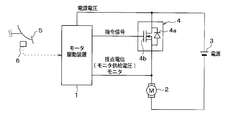
- 1 is a diagram showing a schematic configuration of a motor drive device according to a first embodiment of the present invention and a drive circuit of an electric motor 2 driven by the motor drive device 1;
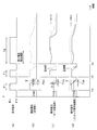
- 6 is a timing chart showing the relationship between a failure mode and a contact potential (motor supply voltage and regenerative voltage).
- 4 is a timing chart showing a time change of a motor current and a time change of a motor supply voltage when the electric motor 2 is turned on.
- 4 is a timing chart showing a command signal to a switching element 4 and a waveform of a motor supply voltage corresponding thereto.
- 6 is a timing chart showing a relationship between a failure mode and a motor supply voltage.
- FIG. 1 is a diagram showing a schematic configuration of a motor drive device 1 according to the present embodiment and a drive circuit of an electric motor 2 driven by the motor drive device 1. First, with reference to this figure, the drive circuit etc. of the motor drive device 1 and the electric motor 2 are demonstrated.
- the motor drive device 1 is configured by a known microcomputer having a CPU, ROM, RAM, I / O, and the like, and controls power supply from the DC power source 3 to the electric motor 2 according to a program stored in advance.
- the electric motor 2 is controlled to a desired rotational speed.
- the electric motor 2 is applied as a drive motor for an electric pump (not shown) for brake fluid pressure control.
- the brake fluid discharged from the wheel cylinder of the target wheel by the pump operation based on the drive of the electric motor 2 is returned to the master cylinder side, and the skid prevention control or the traction control is performed.
- the brake fluid is pumped from the master cylinder side by a pump operation based on the drive of the electric motor 2, and the wheel cylinder of the target wheel is pressurized.
- the motor drive device 1 controls the power supply to the electric motor 2 by controlling the switching element 4 provided in the power supply path of the electric motor 2.
- the drive circuit is a high-side drive circuit in which the switching element 4 is connected to the high side of the electric motor 2, and the electric motor 2 is controlled by controlling the switching element 4 on the high side of the electric motor 2. 2 to control power supply. Specifically, on / off of the switching element 4 is controlled by outputting a command signal to the switching element 4.
- a MOS transistor 4b provided with a freewheeling diode 4a is used as the switching element 4, and the MOS transistor 4b is turned on and off by controlling the gate voltage applied to the gate of the MOS transistor 4b.
- the motor drive device 1 monitors a potential at a place where the electric motor 2 and the switching element 4 are connected (hereinafter referred to as a contact potential).
- the contact potential represents a voltage (hereinafter referred to as a motor supply voltage) supplied to the electric motor 2 when the switching element 4 is turned on.
- the contact potential represents a regenerative voltage corresponding to the number of rotations of the electric motor 2. Therefore, by monitoring the contact potential, the motor supply voltage can be monitored when the switching element 4 is turned on, and the regenerative voltage can be monitored when the switching element 4 is switched from off to on.
- the motor drive device 1 determines whether the electric motor 2 or the switching element 4 has failed by determining whether a desired voltage is supplied to the electric motor 2 based on the monitoring result of the contact potential. Is going. Details of this failure determination will be described later.
- the voltage (power supply voltage) of the DC power supply 3 is input to the motor drive device 1 so that the voltage level of the DC power supply 3 can be monitored.
- the motor drive device 1 receives a detection signal of an operation amount detection device 6 that detects an operation amount of a brake operation member 5 such as a brake pedal or a brake lever. Based on the detection signal of the operation amount detection device 6, the motor drive device 1 can monitor the operation amount of the brake operation member 5.
- the motor drive device 1 of the present embodiment outputs a command signal to drive the electric motor 2 when executing the timing for driving the electric motor 2, for example, the above-described anti-skid control, skid prevention control, or traction control.
- failure determination is performed, for example, at the time of an initial check performed when the ignition switch is turned on. First, the basic concept of this failure determination will be described.
- the types of failure to be determined include a case where the electric motor 2 fails due to the rotating shaft being fixed or the like, and switching in which a desired voltage cannot be supplied to the electric motor 2 due to a large voltage drop at the switching element 4. There is a case where the element 4 has failed.
- the voltage of the DC power supply 3 is a constant value
- the form of change in the regenerative voltage varies depending on the form of failure. This will be described with reference to FIG.
- FIG. 2 is a timing chart showing the relationship between the failure mode and the contact potential (motor supply voltage and regenerative voltage).
- the voltage of the DC power source 3 is A voltage obtained by subtracting a normal voltage drop at the switching element 4 becomes a motor supply voltage, and is detected as a contact potential.
- a regenerative voltage corresponding to the rotational speed of the electric motor 2 is detected as a contact potential.
- the mode of change of the regenerative voltage at this time depends on the voltage value applied to the electric motor 2 when the switching element 4 is turned on and the time of voltage application to the electric motor 2.
- the electric motor 2 when the electric motor 2 is out of order, the voltage applied to the electric motor 2 during the power supply with the switching element 4 turned on as shown by the broken line in FIG. Although it is the same as when there is no failure, the mode of change of the regenerative voltage immediately after turning off the switching element 4 is different from when the electric motor 2 is not broken. Specifically, when the rotation shaft of the electric motor 2 is fixed, the rotation of the electric motor 2 is hindered, so that the regenerative voltage rapidly decreases at the same time as the switching element 4 is turned off. The speed at which the regenerative voltage decreases at this time is faster than when the electric motor 2 is not broken down. Therefore, it is possible to determine whether or not the electric motor 2 has failed based on how the contact potential changes after the switching element 4 is turned off, that is, how the contact potential is reduced.
- the switching element 4 when the switching element 4 is in failure, as shown by the alternate long and short dash line in FIG. 2, compared with the case where the electric motor 2 has not failed, power is being supplied with the switching element 4 turned on. In addition, the voltage applied to the electric motor 2 becomes small. That is, since the voltage drop at the switching element 4 increases, the motor supply voltage decreases accordingly. Moreover, the mode of change of the regenerative voltage immediately after the switching element 4 is turned off is also different from that in the case where the switching element 4 is not broken down. That is, since the motor supply voltage during power supply with the switching element 4 on is different depending on whether or not the switching element 4 has failed, the rotational speed of the electric motor 2 also varies depending on whether or not the switching element 4 has failed. come.
- the regenerative voltage also has a different value depending on whether or not the switching element 4 has failed.
- the contact potential is earlier than when the switching element 4 is not faulty. Becomes a low value.
- the switching element 4 breaks down based on the level of the contact potential when the switching element 4 is turned on or the manner in which the contact potential changes after the switching element 4 is turned off, that is, how the contact potential is lowered. It can be determined whether or not.
- the motor drive device 1 of the present embodiment can determine the failure of the electric motor 2 or the failure of the switching element 4.
- the current supplied to the electric motor 2 becomes a large value for a predetermined period (for example, several hundred ms) due to the occurrence of the inrush current.
- the voltage drop at the element 4 also increases. This state is represented as in the timing chart of the time change of the motor current and the time change of the motor supply voltage shown in FIGS.
- the motor supply voltage is detected as a small value, and it may be erroneously determined that the switching element 4 is out of order. Therefore, during the period when the inrush current is generated, it is determined that the switching element 4 has failed based on the contact potential, and the failure is based on the contact potential after the transition to the steady state thereafter. It is necessary to make a judgment.
- the motor supply voltage waits until the motor supply voltage reaches a steady state while avoiding the period in which the inrush current is generated, it takes time for the failure determination, and power is supplied to the electric motor 2 during the failure determination. It will increase the time to supply.
- the electric motor 2 is not rotated for original control execution, but is rotated for failure determination, so that the operation sound and vibration of the electric motor 2 are generated for a long time. Will be reduced. For this reason, it is preferable that the time required for failure determination and the time for driving the electric motor 2 for failure determination are as short as possible.
- the failure determination is compared with the case where all the cases where the failure determination is completed are performed. It is possible to reduce the time required for the electric motor 2 and the driving time of the electric motor 2 for failure determination. Therefore, in this embodiment, the failure determination is performed as follows. This will be described with reference to FIG.
- FIG. 4 is a timing chart showing a command signal to the switching element 4 and a waveform of a contact potential corresponding thereto.
- FIG. 4A is a waveform showing a command signal to the switching element 4
- FIG. 4B is a waveform of a contact potential when both the electric motor 2 and the switching element 4 are normal
- FIG. 4C shows the waveform of the contact potential when the switching element 4 fails
- FIG. 4D shows the waveform of the contact potential when the electric motor 2 fails.
- the switching element 4 is turned on at the time ta in the motor driving device 1, and then a command signal for turning on the switching element 4 for a first predetermined time T1 is output.
- the first predetermined time T1 during which the switching element 4 is turned on at this time is set regardless of whether or not the inrush current is generated, and the electric power supply to the electric motor 2 is continued during the time T1.
- the switching element 4 is switched from on to off in the motor drive device 1.
- the contact potential from when the switching element 4 is switched off is acquired, and the change mode of the contact potential (regenerative voltage) is confirmed. That is, the mode of change in the contact potential is assumed when the electric motor 2 and the switching element 4 are normal, or when either the electric motor 2 or the switching element 4 is out of order. It is determined whether it is a mode to be performed.
- the time taken from when the switching element 4 is turned off until the contact potential becomes equal to or lower than the second threshold potential Vth2 is measured as the time T, and the time T is equal to or greater than the threshold time Tth.
- the threshold time Tth is shorter than the time t1 when the electric motor 2 and the switching element 4 are assumed to be normal, and the switching element 4 fails.
- the motor drive device 1 is an aspect assumed when the mode of change of the contact potential is normal in both the electric motor 2 and the switching element 4, that is, the electric motor 2 and the switching element 4 are normal and no failure has occurred. Is determined, the failure determination process is terminated at that time.
- the command signal to the switching element 4 is a signal for turning off the switching element 4 as indicated by a broken line in FIG. 4A, and the failure determination process is completed.
- the contact potential becomes zero as shown by the solid line in FIG. 4B, but the case where the subsequent failure determination is continued.
- the waveform of the contact potential when failure determination is continued with a broken line in the figure is shown.
- the failure determination is continued thereafter. Specifically, the process of turning on the switching element 4 at the time tb, turning off the switching element 4 after the first predetermined time T1 has elapsed, and confirming the state of change of the contact potential at that time is repeated once more. . If the mode of change in the contact potential is not a mode assumed when both the electric motor 2 and the switching element 4 are normal even if this process is continuously performed twice, then the electric motor 2 and the switching element 4 A process is performed to identify which one has failed.
- the motor drive device 1 turns on the switching element 4 at time tc, and then outputs a command signal that turns on the switching element 4 for a second predetermined time T2.
- the second predetermined time T2 for turning on the switching element 4 at this time is set to a time longer than the first predetermined time T1 and longer than the generation period of the inrush current.
- the second predetermined time T2 is set to the electric motor 2. Power supply continues. Thereafter, the switching element 4 is switched from on to off in the motor drive device 1. Then, the motor drive device 1 acquires the contact potential from when the switching element 4 is switched off, and identifies which of the electric motor 2 and the switching element 4 is in failure based on the magnitude of the contact potential. To do.
- the motor drive device 1 determines that the electric motor 2 has failed if the contact potential exceeds the first threshold potential Vth1, and the switching element if the contact potential does not exceed the first threshold voltage Vth. 4 is determined as a failure.
- the motor supply voltage applied to the electric motor 2 is the same as that during normal operation.
- the switching element 4 Since the voltage drop at the point becomes large, the motor supply voltage is lower than that at the normal time.
- the first threshold value is lower than the motor supply voltage assumed in the normal state and higher than the motor supply voltage assumed when the switching element 4 has failed. Based on whether or not the contact potential exceeds the first threshold voltage Vth1 as the voltage Vth1, it can be determined which of the electric motor 2 and the switching element 4 has failed.
- the switching element 4 is turned on for a short time of the first predetermined time T1, then turned off, and the electric drive is performed based on the change in contact potential when the switching element 4 is turned off. It is determined whether the motor 2 or the switching element 4 is out of order.
- the switching element 4 is turned on for a time longer than the first predetermined time T1, which is the second predetermined time T2, and which of the electric motor 2 and the switching element 4 has failed based on the magnitude of the contact potential at that time? Has been identified.
- the motor drive device 1 can detect the failure of the switching element 4 in addition to the failure of the electric motor 2.
- the subsequent failure determination is performed. I do not do it. For this reason, when it is normal, it is possible to reduce the time required for failure determination, and it is not necessary to generate the operation sound and vibration of the electric motor 2 for a long time, and the merchantability is not deteriorated.
- the motor drive device 1 of the present embodiment has a threshold time Tth that is variable with respect to the first embodiment, and is otherwise the same as that of the first embodiment, and therefore, different parts from the first embodiment. Only explained.
- the threshold time Tth is a value that is compared with the measured time T taken from when the switching element 4 is turned off until the contact potential (regenerative voltage) becomes equal to or lower than the second threshold potential Vth2.
- the switching element 4 is turned on at the initial check, and the contact potential at that time is compared with the first threshold voltage Vth1, thereby determining which of the electric motor 2 and the switching element 4 has failed. Judgment.
- the brake operation is basically not performed, so that it is possible to easily determine the failure. However, there is a possibility that the brake operation is performed at the time of the initial check.
- the failure determination corresponding to the operation amount of the brake operation member 5 is performed, so that even if the change in the contact potential at the time of stopping the power supply is changed according to the load applied to the electric motor 2, It is possible to make a correct failure determination.
- the motor drive device 1 receives a detection signal indicating the operation amount of the brake operation member 5 from the operation amount detection device 6 and monitors the operation amount of the brake operation member 5 based on the detection signal.
- the threshold time Tth is varied according to the amount of operation of the brake operation member 5 at that time. That is, even if the electric motor 2 and the switching element 4 are not broken down, the larger the load applied to the electric motor 2, the more the contact potential becomes lower than the second threshold potential Vth2 after the switching element 4 is turned off. The time T required until the time becomes smaller. Therefore, the threshold time Tth is reduced as the operation amount of the brake operation member 5 is increased.
- the threshold time Tth can be varied correspondingly, so that accurate failure determination can be performed. It becomes.
- the motor drive device 1 of the present embodiment also has a threshold time Tth that is variable with respect to the first embodiment, and is otherwise the same as the first embodiment, and therefore, different parts from the first embodiment. Only explained.
- the threshold time Tth is a value that is compared with the measured time T taken from when the switching element 4 is turned off until the contact potential becomes equal to or lower than the second threshold potential Vth2.
- the threshold time Tth of the first embodiment is shorter than the time t1 when the electric motor 2 and the switching element 4 are assumed to be normal, and the switching element 4 is set longer than the time t2 when it is assumed that a failure has occurred. This is set assuming that the voltage level of the DC power supply 3 is a constant value (for example, 12V).
- the voltage level of the DC power supply 3 may change.
- the voltage applied to the electric motor 2 when the switching element 4 is turned on changes.
- the motor supply voltage also fluctuates in accordance with the voltage level of the DC power supply 3, and fluctuates more than the time taken from when the switching element 4 is turned off until the contact potential becomes equal to or lower than the second threshold potential Vth2.
- the failure determination corresponding to the voltage level of the DC power supply 3 is performed, so that even if the change of the contact potential when the power supply is stopped changes according to the supply voltage to the electric motor 2, It is possible to make a correct failure determination.
- the motor drive device 1 monitors the voltage of the DC power supply 3 and varies the threshold time Tth based on the voltage of the DC power supply 3 at the time of failure determination. That is, even if the electric motor 2 and the switching element 4 are not broken down, the smaller the voltage applied to the electric motor 2, the more the contact potential becomes lower than the second threshold potential Vth2 after the switching element 4 is turned off. The time T taken until the time becomes smaller. For this reason, the threshold time Tth is decreased as the voltage of the DC power supply 3 is decreased.
- the threshold time Tth can be varied correspondingly, so accurate failure determination is possible. Can be done.
- the motor drive device 1 of the present embodiment is a modification of the method for determining whether the electric motor 2 and the switching element 4 are normal, or any of them is out of order with respect to the first embodiment. . Since other aspects are the same as those in the first embodiment, only portions different from those in the first embodiment will be described.
- the switching element 4 is turned on for the first predetermined time T1, and then the switching element 4 is turned off. It is determined whether the motor 2 and the switching element 4 are normal or any of them is malfunctioning. However, in the present embodiment, a determination method different from those in the first to third embodiments is used. This will be described with reference to FIG.
- FIG. 5 is a timing chart showing the relationship between the failure mode and the contact potential (motor supply voltage and regenerative voltage). As shown in this figure, the mode of change of the contact potential varies depending on whether the electric motor 2 and the switching element 4 are normal or one of them is out of order. Compared with the case where the electric motor 2 and the switching element 4 are normal, when either the electric motor 2 or the switching element 4 is out of order, the contact potential becomes a lower value.
- a predetermined set time T SET has passed since turning off. Is obtained, and based on the magnitude of the contact potential, it is determined whether the electric motor 2 and the switching element 4 are normal or any of them is malfunctioning. Specifically, if the set potential V SET or the contact potential is determined in advance of that time, the electric motor 2 and the switching element 4 is determined to be normal, if less than the set potential V SET, the electric It is determined that the motor 2 or the switching element 4 has failed.
- the electric motor 2 and the switching element 4 are normal based on the magnitude of the contact potential when the set time T SET elapses after the switching element 4 is turned off, or one of these is determined. It can be determined whether a failure has occurred. Then, after determining whether the electric motor 2 and the switching element 4 are normal by the above method or one of them is malfunctioning, if it is normal, then the malfunction determination is terminated. Thereafter, by performing the switching element 4 only for the second predetermined time T2, it is possible to specify which of the electric motor 2 and the switching element 4 has failed. Even by such a determination method, the same effect as that of the first embodiment can be obtained.
- the set potential V SET can be made variable based on the operation amount of the brake operation member 5. That is, since the load applied to the electric motor 2 changes according to the operation amount of the brake operation member 5, the mode of change of the contact potential when the power supply is stopped changes according to the magnitude of the load. For this reason, the motor drive device 1 receives a detection signal indicating the operation amount of the brake operation member 5 from the operation amount detection device 6 and monitors the operation amount of the brake operation member 5 based on the detection signal.
- the set potential V SET is made variable according to the operation amount of the brake operation member 5 at that time. Specifically, the set potential V SET is decreased as the operation amount of the brake operation member 5 is increased. In this way, even if the load applied to the electric motor 2 is increased based on the operation of the brake operation member 5, the set potential V SET can be changed correspondingly, so that accurate failure determination can be performed. It becomes.
- the set potential V SET can be made variable based on the voltage of the DC power supply 3. That is, the motor supply voltage varies according to the voltage level of the DC power supply 3. For this reason, the motor drive device 1 monitors the voltage of the DC power supply 3, and at the time of failure determination, makes the set potential V SET variable based on the voltage of the DC power supply 3 at that time. In this way, even if the voltage applied to the electric motor 2 fluctuates in accordance with the fluctuation of the voltage level of the DC power supply 3, the set potential V SET can be changed correspondingly, so accurate failure determination is possible. Can be done.
- the switching element 4 is turned on for the first predetermined time T1
- the switching element 4 is switched from on to off, and the subsequent contact potential (regenerative voltage) is acquired.
- the above series of processes may be executed only once, or may be repeatedly executed three or more times. If the series of processes is executed only once, the failure determination can be realized by a simple process. In addition, as the number of times the series of processes are repeatedly executed is increased, it is possible to accurately determine whether any of the electric motor 2 and the switching element 4 has failed.
- the first predetermined time T1 of each floor is different from each other.
- the first predetermined time T1 of the process executed first If it is determined in the previous process that the electric motor 2 and the switching element 4 have not failed, the subsequent process is not executed, so that the drive time of the electric motor 2 can be shortened. That is, it is possible to shorten the operation sound and vibration generation time of the electric motor 2 while improving the determination accuracy of the failure determination.
- a threshold value for evaluating the line voltage acquired at each time is determined. It is preferable that Tth and the set voltage V SET are set according to each first predetermined time T1. Thereby, it can be determined more accurately whether any of the electric motor 2 and the switching element 4 is out of order.
- the threshold time Tth is made variable based on the voltage of the DC power supply 3
- the set potential VSET is made variable based on the voltage of the DC power supply 3.
- the first threshold potential Vth1 can be made variable based on the voltage of the DC power supply 3.
- the first threshold potential Vth1 is a value that is compared with the contact potential in order to identify which one has failed when it is determined that the electric motor 2 or the switching element 4 has failed.
- the contact potential at this time is not a regenerative voltage but a motor supply voltage when the switching element 4 is turned on. Since the motor supply voltage also varies according to the voltage level of the DC power supply 3, it is preferable to vary the first threshold potential Vth1 accordingly. For this reason, by making the first threshold potential Vth1 smaller as the voltage of the DC power source 3 becomes smaller, it is possible to more accurately identify which of the electric motor 2 and the switching element 4 is malfunctioning. Become.
- the MOS transistor 4b is described as an example of the switching element 4.
- the MOS transistor 4b is not limited, and other elements (for example, an IGBT or a relay) can be used.
- the determination which identifies which of the electric motor 2 and the switching element 4 has failed is performed. .
- means for realizing each function is realized by a program stored in advance. That is, in the motor drive device 1, the means for outputting a command signal for turning on the switching element 4 for the first predetermined time T1 corresponds to the first power supply control means. Means for obtaining the contact potential from when the switching element 4 is turned on after being turned on for the first predetermined time T1 corresponds to first contact potential obtaining means. The means for outputting a command signal for turning on the switching element 4 for the second predetermined time T2 corresponds to the second power supply control means. Means for obtaining the contact potential from when the switching element 4 is turned on after being turned on for the second predetermined time T2 corresponds to second contact potential obtaining means.
- the means corresponds to the first determination means.
- Means for determining whether or not the contact potential acquired by the second contact potential acquisition means is equal to or higher than the first threshold potential Vth1 corresponds to the second determination means.
- the means for specifying which of the electric motor 2 and the switching element 4 is in failure based on the results of the first and second determination means corresponds to the failure specifying means.
- the means for reducing the threshold time Tth as the amount of operation of the brake operation member 5 is larger corresponds to the brake operation amount / threshold time setting means.
- the means for reducing the threshold time Tth as the voltage of the DC power supply 3 is smaller corresponds to the power supply voltage / threshold time setting means.
- the means for decreasing the set potential V SET as the operation amount of the brake operation member 5 corresponds to the brake operation amount versus potential setting means.
- the means for reducing the set potential V SET as the voltage of the DC power supply 3 is equivalent to the power supply voltage versus potential setting means.
Landscapes
- Engineering & Computer Science (AREA)
- Power Engineering (AREA)
- Control Of Electric Motors In General (AREA)
- Control Of Direct Current Motors (AREA)
Abstract
Description
本発明の第1実施形態について説明する。図1は、本実施形態にかかるモータ駆動装置1およびモータ駆動装置1によって駆動される電動モータ2の駆動回路等の概略構成を示した図である。まず、この図を参照して、モータ駆動装置1および電動モータ2の駆動回路等について説明する。
本発明の第2実施形態について説明する。本実施形態のモータ駆動装置1は、第1実施形態に対してしきい時間Tthを可変にしたものであり、その他に関しては第1実施形態と同様であるため、第1実施形態と異なる部分についてのみ説明する。
本発明の第3実施形態について説明する。本実施形態のモータ駆動装置1も、第1実施形態に対してしきい時間Tthを可変にしたものであり、その他に関しては第1実施形態と同様であるため、第1実施形態と異なる部分についてのみ説明する。
本発明の第4実施形態について説明する。本実施形態のモータ駆動装置1は、第1実施形態に対して電動モータ2およびスイッチング素子4が正常であるか、もしくはこれらのいずれかが故障しているかを判定する手法を変更したものである。その他に関しては第1実施形態と同様であるため、第1実施形態と異なる部分についてのみ説明する。
上記第1~第4実施形態では、スイッチング素子4を第1所定時間T1だけオンさせた後に当該スイッチング素子4をオンからオフに切替えて、その後の接点電位(回生電圧)を取得する一連の処理を2回だけ繰り返し実行するようにした。しかしながら、上記一連の処理を、1回だけ実行するようにしても良いし、3回以上繰り返し実行するようにしても良い。上記一連の処理を1回だけ実行するようにすれば、故障判定をシンプルな処理で実現することができる。また、上記一連の処理を繰り返し実行する回数を多くするほど、電気モータ2およびスイッチング素子4のいずれかが故障しているか否かを正確に判定することができる。
Claims (13)
- 電気モータ(2)に電力を供給する直流電源(3)と、前記電気モータ(2)と前記直流電源(3)との間の電力供給経路をオンオフするスイッチング素子(4)とを備える電気モータ(2)の駆動回路に適用され、前記スイッチング素子(4)により前記電気モータ(2)への電力供給を制御するモータ駆動装置において、
前記スイッチング素子(4)をオンからオフに切替えたときの前記電気モータ(2)への電力供給終了に伴って変化する前記電気モータ(2)と前記スイッチング素子(4)との間の接点電位を取得する第1接点電位取得手段と、
前記スイッチング素子(4)にオンしているときの前記電気モータ(2)への電力供給中の前記接点電位を取得する第2接点電位取得手段と、
前記第1接点電位取得手段により取得された前記接点電位に基づいて、前記電気モータ(2)への電力供給停止に伴う前記接点電位の変化の態様が、前記電気モータ(2)および前記スイッチング素子(4)が正常時の態様か、前記電気モータ(2)もしくは前記スイッチング素子(4)が故障時の態様であるかを判定する第1判定手段と、
前記第2接点電位取得手段により取得された前記接点電位が、所定の第1しきい電位(Vth1)以上であるか否かを判定する第2判定手段と、
前記第1判定手段にて前記接点電位の変化の態様が前記正常時の態様であると判定されると前記電気モータ(2)および前記スイッチング素子(4)が正常であるとし、前記第1判定手段にて前記接点電位の変化の態様が前記故障時の態様であると判定され、かつ、前記第2判定手段にて前記接点電位が所定の第1しきい電位(Vth1)以上と判定されれば前記電気モータ(2)の故障と特定し、前記第1判定手段にて前記接点電位の変化の態様が前記故障時の態様であると判定され、かつ、前記第2判定手段にて、前記接点電位が所定の第1しきい電位(Vth1)未満と判定されれば前記スイッチング素子(4)の故障と特定する故障特定手段と、を備えていることを特徴とするモータ駆動装置。 - 前記第2接点電位取得手段は、前記第2電力供給制御手段による前記電気モータ(2)への電力供給が行なわれてから、前記突入電流の発生期間経過後の前記接点電位を取得することを特徴とする請求項1に記載のモータ駆動装置。
- 前記スイッチング素子(4)を第1所定時間(T1)だけオンして前記電気モータ(2)に対して電力供給を行う第1電力供給制御手段と、
前記スイッチング素子(4)をオンしたときに発生する突入電流の発生期間よりも長い第2所定時間(T2)だけオンして前記電気モータ(2)に対して電力供給を行う第2電力供給制御手段とを備え、
前記第1接点電位取得手段は、前記第1電力供給制御手段による前記電気モータ(2)への電力供給終了に伴い変化する前記接点電位を取得し、
前記第2接点電位取得手段は、前記第2電力供給制御手段による前記電気モータ(2)への電力供給が開始されてから、前記突入電流の発生期間経過後の前記接点電位を取得し、
前記第1電力供給制御手段による前記電力供給および前記第1接点電位取得手段による前記接点電位の取得を、前記第2電力供給制御手段による前記電力供給および前記第2接点電位取得手段による前記接点電位の取得よりも先に行うことを特徴とする請求項1または2に記載のモータ駆動装置。 - 前記第2電力供給制御手段による前記電力供給および前記第2接点電位取得手段による前記接点電位の取得は、前記第1判定手段にて前記接点電位の変化の態様が前記故障時の態様であると判定されたときにのみ行なわれ、前記第1判定手段にて前記接点電位の変化の態様が前記正常時の態様であると判定されたときには行なわれないことを特徴とする請求項3に記載のモータ駆動装置。
- 前記第2電力供給手段による前記電力供給および前記第2接点電位取得手段による前記接点電位の取得を行うよりも先に、前記第1電力供給制御手段による前記電力供給および前記第1接点電位取得手段による前記接点電位の取得を、複数回行うことを特徴とする請求項3または4に記載のモータ駆動装置。
- 前記複数回にわたる前記第1電力供給制御手段による前記電力供給および前記第1接点電位取得手段による前記接点電位の取得において、先に行う電力供給ほど同電力供給の前記第1所定時間が短く、
前記第1電力供給制御手段による次の前記電力供給は、前記第1判定手段にて前記第1接点電位取得により先に取得された前記接点電位に基づく前記接点電位の態様が故障時の態様と判定されたときのみに行われ、前記先に取得された前記接点電位に基づく前記接点電位の変化の態様が正常時の態様と判定されたときは行われないことを特徴とする請求項5に記載のモータ駆動装置。 - 前記第1判定手段は、前記第1接点電位取得手段にて取得される前記接点電位が所定の第2しきい電位(Vth2)以下になったか否かを判定すると共に、前記電気モータ(2)への電力供給が終了した時点から当該接点電位が前記第2しきい電位(Vth2)以下になったことが判定される時点までの時間を経時時間(T)として、該計時時間(T)が所定のしきい時間(Tth)以上である場合に、前記接点電位の変化の態様が前記正常時の態様と判定し、該計時時間(T)が前記しきい時間(Tth)未満である場合に、前記接点電位の変化の態様が前記故障時の態様と判定することを特徴とする請求項1ないし6のいずれか1つに記載のモータ駆動装置。
- 前記電気モータ(2)は、車両のブレーキ装置においてブレーキ液圧を加圧する電動ポンプを駆動するものであり、
前記ブレーキ装置を操作するためのブレーキ操作部材(5)の操作量を検出するブレーキ操作量検出手段と、
前記ブレーキ操作量検出手段により検出された操作量が大きいほど、前記しきい時間(Tth)を小さくするブレーキ操作量対しきい時間設定手段と、を備えていることを特徴とする請求項7に記載のモータ駆動装置。 - 前記直流電源(3)の電圧を検出する電源電圧検出手段と、
前記電源電圧検出手段により検出された前記直流電源(3)の電圧が小さいほど、前記しきい時間(Tth)を小さくする電源電圧対しきい時間設定手段と、を備えていることを特徴とする請求項7または8に記載のモータ駆動装置。 - 前記第1接点電位取得手段は、前記電気モータ(2)への電力供給が終了した時点から所定の設定時間(TSET)が経過した時点の前記接点電位を取得し、
前記第1判定手段は、前記第1接点電位取得手段により取得された前記接点電位が所定の設定電位(VSET)以上である場合に、前記接点電位の変化の態様が前記正常時の態様と判定し、前記第1接点電位取得手段により取得された前記接点電位が所定の設定電位(VSET)未満である場合に、前記接点電位の変化の態様が前記故障時の態様と判定することを特徴とする請求項1ないし6のいずれか1つに記載のモータ駆動回路。 - 前記電気モータ(2)は、車両のブレーキ装置においてブレーキ液圧を加圧する電動ポンプを駆動するものであり、
前記ブレーキ装置を操作するためのブレーキ操作部材(5)の操作量を検出するブレーキ操作量検出手段と、
前記ブレーキ操作量検出手段により検出された操作量が大きいほど、前記設定電位(VSET)を小さくするブレーキ操作量対電位設定手段と、を備えていることを特徴とする請求項10に記載のモータ駆動装置。 - 前記直流電源(3)の電圧を検出する電源電圧検出手段と、
前記電源電圧検出手段により検出された前記直流電源(3)の電圧が小さいほど、前記設定電位(VSET)を小さくする電源電圧対電位設定手段と、を備えていることを特徴とする請求項10または11に記載のモータ駆動装置。 - 前記直流電源(3)の電圧を検出する電源電圧検出手段と、
前記電源電圧検出手段により検出された前記直流電源(3)の電圧が小さいほど、前記第1しきい電位(Vth1)を小さくする第1しきい電位設定手段と、を備えていることを特徴とする請求項1ないし12のいずれか1つに記載のモータ駆動装置。
Priority Applications (2)
| Application Number | Priority Date | Filing Date | Title |
|---|---|---|---|
| US13/580,585 US8803462B2 (en) | 2010-02-24 | 2011-02-24 | Motor drive unit |
| DE112011100651T DE112011100651T5 (de) | 2010-02-24 | 2011-02-24 | Motorantriebsvorrichtung |
Applications Claiming Priority (2)
| Application Number | Priority Date | Filing Date | Title |
|---|---|---|---|
| JP2010038779A JP5493988B2 (ja) | 2010-02-24 | 2010-02-24 | モータ駆動装置 |
| JP2010-038779 | 2010-02-24 |
Publications (1)
| Publication Number | Publication Date |
|---|---|
| WO2011105468A1 true WO2011105468A1 (ja) | 2011-09-01 |
Family
ID=44506868
Family Applications (1)
| Application Number | Title | Priority Date | Filing Date |
|---|---|---|---|
| PCT/JP2011/054086 Ceased WO2011105468A1 (ja) | 2010-02-24 | 2011-02-24 | モータ駆動装置 |
Country Status (4)
| Country | Link |
|---|---|
| US (1) | US8803462B2 (ja) |
| JP (1) | JP5493988B2 (ja) |
| DE (1) | DE112011100651T5 (ja) |
| WO (1) | WO2011105468A1 (ja) |
Cited By (3)
| Publication number | Priority date | Publication date | Assignee | Title |
|---|---|---|---|---|
| JP2013241162A (ja) * | 2012-05-23 | 2013-12-05 | Mitsubishi Electric Corp | 電動パワーステアリング装置 |
| US20140255211A1 (en) * | 2013-03-05 | 2014-09-11 | Hitachi Automotive Systems, Ltd. | Motor drive device and motor drive method for vehicle electric pump |
| WO2019044533A1 (ja) * | 2017-08-28 | 2019-03-07 | 株式会社東海理化電機製作所 | モータ制御装置 |
Families Citing this family (5)
| Publication number | Priority date | Publication date | Assignee | Title |
|---|---|---|---|---|
| KR20150134061A (ko) * | 2014-05-21 | 2015-12-01 | 주식회사 만도 | 전자 제어 주행 안정 장치 및 그것의 모터 프리휠링 회로 고장 검출 방법 |
| JP6423765B2 (ja) * | 2015-07-31 | 2018-11-14 | ファナック株式会社 | ブレーキの作動及び解除異常を検知する機能を有するブレーキ装置 |
| DE102016002740A1 (de) * | 2016-03-07 | 2017-09-07 | Andreas Stihl Ag & Co. Kg | Verfahren und Vorrichtung zur Überprüfung der Funktion einer Ansteuerschaltung eines Gleichstrommotors |
| JP6205521B1 (ja) * | 2016-08-25 | 2017-09-27 | 新電元工業株式会社 | 制御方法、及び制御装置 |
| KR102840111B1 (ko) * | 2017-01-18 | 2025-07-31 | 엘지전자 주식회사 | 리니어 압축기의 제어 장치 |
Citations (4)
| Publication number | Priority date | Publication date | Assignee | Title |
|---|---|---|---|---|
| JPH06343289A (ja) * | 1993-05-28 | 1994-12-13 | Nisshinbo Ind Inc | モータ異常検出装置 |
| JPH07165055A (ja) * | 1993-10-01 | 1995-06-27 | Sumitomo Electric Ind Ltd | アンチスキッド制御装置のモータ故障判定装置 |
| JPH11241637A (ja) * | 1998-02-26 | 1999-09-07 | Denso Corp | 直流モータ駆動系の異常検出装置 |
| JP2008043051A (ja) * | 2006-08-07 | 2008-02-21 | Fujitsu Ten Ltd | 車載制御装置 |
Family Cites Families (2)
| Publication number | Priority date | Publication date | Assignee | Title |
|---|---|---|---|---|
| US4691149A (en) * | 1985-10-11 | 1987-09-01 | Caterpillar Industrial Inc. | Apparatus and method for protecting a motor control circuit |
| JP3587300B2 (ja) * | 2001-01-16 | 2004-11-10 | 株式会社デンソー | 集積回路装置 |
-
2010
- 2010-02-24 JP JP2010038779A patent/JP5493988B2/ja not_active Expired - Fee Related
-
2011
- 2011-02-24 US US13/580,585 patent/US8803462B2/en not_active Expired - Fee Related
- 2011-02-24 DE DE112011100651T patent/DE112011100651T5/de not_active Ceased
- 2011-02-24 WO PCT/JP2011/054086 patent/WO2011105468A1/ja not_active Ceased
Patent Citations (4)
| Publication number | Priority date | Publication date | Assignee | Title |
|---|---|---|---|---|
| JPH06343289A (ja) * | 1993-05-28 | 1994-12-13 | Nisshinbo Ind Inc | モータ異常検出装置 |
| JPH07165055A (ja) * | 1993-10-01 | 1995-06-27 | Sumitomo Electric Ind Ltd | アンチスキッド制御装置のモータ故障判定装置 |
| JPH11241637A (ja) * | 1998-02-26 | 1999-09-07 | Denso Corp | 直流モータ駆動系の異常検出装置 |
| JP2008043051A (ja) * | 2006-08-07 | 2008-02-21 | Fujitsu Ten Ltd | 車載制御装置 |
Cited By (4)
| Publication number | Priority date | Publication date | Assignee | Title |
|---|---|---|---|---|
| JP2013241162A (ja) * | 2012-05-23 | 2013-12-05 | Mitsubishi Electric Corp | 電動パワーステアリング装置 |
| US20140255211A1 (en) * | 2013-03-05 | 2014-09-11 | Hitachi Automotive Systems, Ltd. | Motor drive device and motor drive method for vehicle electric pump |
| US10393105B2 (en) * | 2013-03-05 | 2019-08-27 | Hitachi Automotive Systems, Ltd. | Motor drive device and motor drive method for vehicle electric pump |
| WO2019044533A1 (ja) * | 2017-08-28 | 2019-03-07 | 株式会社東海理化電機製作所 | モータ制御装置 |
Also Published As
| Publication number | Publication date |
|---|---|
| DE112011100651T5 (de) | 2012-12-27 |
| JP5493988B2 (ja) | 2014-05-14 |
| US8803462B2 (en) | 2014-08-12 |
| US20120313561A1 (en) | 2012-12-13 |
| JP2011176935A (ja) | 2011-09-08 |
Similar Documents
| Publication | Publication Date | Title |
|---|---|---|
| JP5493988B2 (ja) | モータ駆動装置 | |
| US8789645B2 (en) | Electric power steering device | |
| CN104648369B (zh) | 用于电动驻车制动器的控制装置 | |
| US10153715B2 (en) | Motor driving control device and motor driving control method | |
| JP2014105857A (ja) | 油圧センサ故障診断方法及びシステム | |
| US9979331B2 (en) | Method for controlling a motor | |
| JP5035059B2 (ja) | 車両制御装置 | |
| JP6098156B2 (ja) | 故障診断機能を備えた負荷駆動装置 | |
| US20190047533A1 (en) | Brake device for vehicle | |
| KR20150134061A (ko) | 전자 제어 주행 안정 장치 및 그것의 모터 프리휠링 회로 고장 검출 방법 | |
| KR101914127B1 (ko) | 모터의 고장 감지 장치 | |
| JP2004314756A (ja) | 電動駐車ブレーキシステム | |
| JP2011176935A5 (ja) | ||
| US10978986B2 (en) | Electric power steering device | |
| US10112644B2 (en) | Method for operating a steering system | |
| JP5099041B2 (ja) | 燃料ポンプ制御装置 | |
| US9667180B2 (en) | Inverter | |
| US12126292B2 (en) | Motor control device | |
| JP2012044781A (ja) | モータ制御装置及び電動パワーステアリング装置 | |
| JP7173775B2 (ja) | モータ駆動制御装置及びモータの駆動制御方法 | |
| JP5980039B2 (ja) | 負圧ポンプ制御装置 | |
| JP2009131069A (ja) | モータ制御装置 | |
| JP5135971B2 (ja) | 電動パワーステアリング装置のモータ制御装置 | |
| JP2014204446A (ja) | モータ制御装置、およびモータ制御装置を備えた電動パワーステアリング装置 | |
| KR101562404B1 (ko) | 펌프모터 구동부의 고장 감지장치 및 방법 |
Legal Events
| Date | Code | Title | Description |
|---|---|---|---|
| 121 | Ep: the epo has been informed by wipo that ep was designated in this application |
Ref document number: 11747428 Country of ref document: EP Kind code of ref document: A1 |
|
| WWE | Wipo information: entry into national phase |
Ref document number: 13580585 Country of ref document: US |
|
| WWE | Wipo information: entry into national phase |
Ref document number: 112011100651 Country of ref document: DE Ref document number: 1120111006519 Country of ref document: DE |
|
| 122 | Ep: pct application non-entry in european phase |
Ref document number: 11747428 Country of ref document: EP Kind code of ref document: A1 |