WO2011104852A1 - 車両制御システムおよび車両制御方法 - Google Patents
車両制御システムおよび車両制御方法 Download PDFInfo
- Publication number
- WO2011104852A1 WO2011104852A1 PCT/JP2010/052994 JP2010052994W WO2011104852A1 WO 2011104852 A1 WO2011104852 A1 WO 2011104852A1 JP 2010052994 W JP2010052994 W JP 2010052994W WO 2011104852 A1 WO2011104852 A1 WO 2011104852A1
- Authority
- WO
- WIPO (PCT)
- Prior art keywords
- control
- shift
- switching
- vehicle
- accelerator
- Prior art date
- Legal status (The legal status is an assumption and is not a legal conclusion. Google has not performed a legal analysis and makes no representation as to the accuracy of the status listed.)
- Ceased
Links
Images



Classifications
-
- F—MECHANICAL ENGINEERING; LIGHTING; HEATING; WEAPONS; BLASTING
- F02—COMBUSTION ENGINES; HOT-GAS OR COMBUSTION-PRODUCT ENGINE PLANTS
- F02D—CONTROLLING COMBUSTION ENGINES
- F02D29/00—Controlling engines, such controlling being peculiar to the devices driven thereby, the devices being other than parts or accessories essential to engine operation, e.g. controlling of engines by signals external thereto
- F02D29/02—Controlling engines, such controlling being peculiar to the devices driven thereby, the devices being other than parts or accessories essential to engine operation, e.g. controlling of engines by signals external thereto peculiar to engines driving vehicles; peculiar to engines driving variable pitch propellers
-
- B—PERFORMING OPERATIONS; TRANSPORTING
- B60—VEHICLES IN GENERAL
- B60W—CONJOINT CONTROL OF VEHICLE SUB-UNITS OF DIFFERENT TYPE OR DIFFERENT FUNCTION; CONTROL SYSTEMS SPECIALLY ADAPTED FOR HYBRID VEHICLES; ROAD VEHICLE DRIVE CONTROL SYSTEMS FOR PURPOSES NOT RELATED TO THE CONTROL OF A PARTICULAR SUB-UNIT
- B60W10/00—Conjoint control of vehicle sub-units of different type or different function
- B60W10/04—Conjoint control of vehicle sub-units of different type or different function including control of propulsion units
- B60W10/08—Conjoint control of vehicle sub-units of different type or different function including control of propulsion units including control of electric propulsion units, e.g. motors or generators
-
- B—PERFORMING OPERATIONS; TRANSPORTING
- B60—VEHICLES IN GENERAL
- B60W—CONJOINT CONTROL OF VEHICLE SUB-UNITS OF DIFFERENT TYPE OR DIFFERENT FUNCTION; CONTROL SYSTEMS SPECIALLY ADAPTED FOR HYBRID VEHICLES; ROAD VEHICLE DRIVE CONTROL SYSTEMS FOR PURPOSES NOT RELATED TO THE CONTROL OF A PARTICULAR SUB-UNIT
- B60W10/00—Conjoint control of vehicle sub-units of different type or different function
- B60W10/10—Conjoint control of vehicle sub-units of different type or different function including control of change-speed gearings
- B60W10/11—Stepped gearings
-
- B—PERFORMING OPERATIONS; TRANSPORTING
- B60—VEHICLES IN GENERAL
- B60W—CONJOINT CONTROL OF VEHICLE SUB-UNITS OF DIFFERENT TYPE OR DIFFERENT FUNCTION; CONTROL SYSTEMS SPECIALLY ADAPTED FOR HYBRID VEHICLES; ROAD VEHICLE DRIVE CONTROL SYSTEMS FOR PURPOSES NOT RELATED TO THE CONTROL OF A PARTICULAR SUB-UNIT
- B60W30/00—Purposes of road vehicle drive control systems not related to the control of a particular sub-unit, e.g. of systems using conjoint control of vehicle sub-units
- B60W30/18—Propelling the vehicle
-
- B—PERFORMING OPERATIONS; TRANSPORTING
- B60—VEHICLES IN GENERAL
- B60W—CONJOINT CONTROL OF VEHICLE SUB-UNITS OF DIFFERENT TYPE OR DIFFERENT FUNCTION; CONTROL SYSTEMS SPECIALLY ADAPTED FOR HYBRID VEHICLES; ROAD VEHICLE DRIVE CONTROL SYSTEMS FOR PURPOSES NOT RELATED TO THE CONTROL OF A PARTICULAR SUB-UNIT
- B60W30/00—Purposes of road vehicle drive control systems not related to the control of a particular sub-unit, e.g. of systems using conjoint control of vehicle sub-units
- B60W30/18—Propelling the vehicle
- B60W30/188—Controlling power parameters of the driveline, e.g. determining the required power
-
- B—PERFORMING OPERATIONS; TRANSPORTING
- B60—VEHICLES IN GENERAL
- B60W—CONJOINT CONTROL OF VEHICLE SUB-UNITS OF DIFFERENT TYPE OR DIFFERENT FUNCTION; CONTROL SYSTEMS SPECIALLY ADAPTED FOR HYBRID VEHICLES; ROAD VEHICLE DRIVE CONTROL SYSTEMS FOR PURPOSES NOT RELATED TO THE CONTROL OF A PARTICULAR SUB-UNIT
- B60W50/00—Details of control systems for road vehicle drive control not related to the control of a particular sub-unit, e.g. process diagnostic or vehicle driver interfaces
- B60W50/08—Interaction between the driver and the control system
- B60W50/10—Interpretation of driver requests or demands
-
- F—MECHANICAL ENGINEERING; LIGHTING; HEATING; WEAPONS; BLASTING
- F02—COMBUSTION ENGINES; HOT-GAS OR COMBUSTION-PRODUCT ENGINE PLANTS
- F02D—CONTROLLING COMBUSTION ENGINES
- F02D41/00—Electrical control of supply of combustible mixture or its constituents
- F02D41/02—Circuit arrangements for generating control signals
- F02D41/021—Introducing corrections for particular conditions exterior to the engine
- F02D41/0215—Introducing corrections for particular conditions exterior to the engine in relation with elements of the transmission
- F02D41/0225—Introducing corrections for particular conditions exterior to the engine in relation with elements of the transmission in relation with the gear ratio or shift lever position
-
- F—MECHANICAL ENGINEERING; LIGHTING; HEATING; WEAPONS; BLASTING
- F02—COMBUSTION ENGINES; HOT-GAS OR COMBUSTION-PRODUCT ENGINE PLANTS
- F02D—CONTROLLING COMBUSTION ENGINES
- F02D41/00—Electrical control of supply of combustible mixture or its constituents
- F02D41/02—Circuit arrangements for generating control signals
- F02D41/04—Introducing corrections for particular operating conditions
- F02D41/10—Introducing corrections for particular operating conditions for acceleration
-
- B—PERFORMING OPERATIONS; TRANSPORTING
- B60—VEHICLES IN GENERAL
- B60W—CONJOINT CONTROL OF VEHICLE SUB-UNITS OF DIFFERENT TYPE OR DIFFERENT FUNCTION; CONTROL SYSTEMS SPECIALLY ADAPTED FOR HYBRID VEHICLES; ROAD VEHICLE DRIVE CONTROL SYSTEMS FOR PURPOSES NOT RELATED TO THE CONTROL OF A PARTICULAR SUB-UNIT
- B60W50/00—Details of control systems for road vehicle drive control not related to the control of a particular sub-unit, e.g. process diagnostic or vehicle driver interfaces
- B60W2050/0062—Adapting control system settings
- B60W2050/0075—Automatic parameter input, automatic initialising or calibrating means
- B60W2050/009—Priority selection
- B60W2050/0091—Priority selection of control inputs
-
- B—PERFORMING OPERATIONS; TRANSPORTING
- B60—VEHICLES IN GENERAL
- B60W—CONJOINT CONTROL OF VEHICLE SUB-UNITS OF DIFFERENT TYPE OR DIFFERENT FUNCTION; CONTROL SYSTEMS SPECIALLY ADAPTED FOR HYBRID VEHICLES; ROAD VEHICLE DRIVE CONTROL SYSTEMS FOR PURPOSES NOT RELATED TO THE CONTROL OF A PARTICULAR SUB-UNIT
- B60W2540/00—Input parameters relating to occupants
- B60W2540/10—Accelerator pedal position
-
- B—PERFORMING OPERATIONS; TRANSPORTING
- B60—VEHICLES IN GENERAL
- B60W—CONJOINT CONTROL OF VEHICLE SUB-UNITS OF DIFFERENT TYPE OR DIFFERENT FUNCTION; CONTROL SYSTEMS SPECIALLY ADAPTED FOR HYBRID VEHICLES; ROAD VEHICLE DRIVE CONTROL SYSTEMS FOR PURPOSES NOT RELATED TO THE CONTROL OF A PARTICULAR SUB-UNIT
- B60W2540/00—Input parameters relating to occupants
- B60W2540/16—Ratio selector position
-
- B—PERFORMING OPERATIONS; TRANSPORTING
- B60—VEHICLES IN GENERAL
- B60W—CONJOINT CONTROL OF VEHICLE SUB-UNITS OF DIFFERENT TYPE OR DIFFERENT FUNCTION; CONTROL SYSTEMS SPECIALLY ADAPTED FOR HYBRID VEHICLES; ROAD VEHICLE DRIVE CONTROL SYSTEMS FOR PURPOSES NOT RELATED TO THE CONTROL OF A PARTICULAR SUB-UNIT
- B60W30/00—Purposes of road vehicle drive control systems not related to the control of a particular sub-unit, e.g. of systems using conjoint control of vehicle sub-units
- B60W30/18—Propelling the vehicle
- B60W30/19—Improvement of gear change, e.g. by synchronisation or smoothing gear shift
-
- F—MECHANICAL ENGINEERING; LIGHTING; HEATING; WEAPONS; BLASTING
- F02—COMBUSTION ENGINES; HOT-GAS OR COMBUSTION-PRODUCT ENGINE PLANTS
- F02D—CONTROLLING COMBUSTION ENGINES
- F02D2250/00—Engine control related to specific problems or objectives
- F02D2250/18—Control of the engine output torque
- F02D2250/21—Control of the engine output torque during a transition between engine operation modes or states
-
- F—MECHANICAL ENGINEERING; LIGHTING; HEATING; WEAPONS; BLASTING
- F02—COMBUSTION ENGINES; HOT-GAS OR COMBUSTION-PRODUCT ENGINE PLANTS
- F02D—CONTROLLING COMBUSTION ENGINES
- F02D2250/00—Engine control related to specific problems or objectives
- F02D2250/28—Control for reducing torsional vibrations, e.g. at acceleration
Definitions
- the present invention relates to a vehicle control system and a vehicle control method.
- the driver's request is based on the vehicle speed and the accelerator operation amount (accelerator opening, pedal effort, etc.) when the driver operates the accelerator pedal.
- a so-called torque demand control is performed in which a target acceleration that is an acceleration to be determined is determined, and a power source, for example, an engine throttle opening, a fuel injection amount, an ignition timing, and the like are controlled based on the determined target acceleration.
- a power source for example, an engine throttle opening, a fuel injection amount, an ignition timing, and the like are controlled based on the determined target acceleration.
- a power source is controlled based on a target acceleration or a target driving force, which is a required value corresponding to the acceleration generated in the vehicle, but also an acceleration corresponding to the required value is achieved.
- the automatic transmission is also controlled based on the required value. Also in the vehicle control system that performs such torque demand control, as shown in Patent Document 2, not only automatic shift control for automatically shifting the automatic transmission, but also the automatic transmission is manually shifted by the operation of the driver. Manual shift control can be performed.
- the torque demand control is intended to achieve the feeling of acceleration required by the driver, which is required from the driver's accelerator operation, regardless of the current gear position.
- manual shift control the automatic transmission is shifted according to the driver's intention, and the object is to obtain an acceleration feeling corresponding to the driver's accelerator operation that differs for each shift stage. That is, the manual shift control is a driver's request to improve the controllability of the vehicle by manually shifting the automatic transmission. Therefore, if the vehicle generates the same acceleration as in the automatic shift control during the manual shift control in the torque demand control, the vehicle may not meet the driver's request.
- the present invention has been made in view of the above, and is a vehicle control system that can achieve at least one of improvement in controllability of the vehicle at the time of manual shift control and suppression of a sense of discomfort to the driver. It is another object of the present invention to provide a vehicle control method.
- a power source connected to a drive wheel of a vehicle and controlled based on a control amount, the power source and the drive wheel
- An automatic transmission that controls the shift based on a shift instruction, a shift operation device that instructs a shift by a driver's operation, an accelerator operation amount according to an accelerator operation by the driver, and Automatic shift control for controlling the power source and the automatic transmission based on the control amount determined based on a request value corresponding to acceleration determined based on a vehicle speed and the shift instruction, and the shift operation device
- the automatic transmission is controlled based on the shift instruction from the vehicle, and the acceleration generated in the vehicle by the shift is controlled based on the accelerator operation amount and the vehicle speed.
- a vehicle control device that performs any one of manual shift control that controls the power source based on the control amount that is determined to be greater than that during the automatic shift control, and an operation of the driver
- a control switching instruction device for instructing control switching between the automatic shift control and the manual shift control, and the vehicle control device performs the actual switching operation after the control switching instruction. Is changed according to the operation of the accelerator.
- the switching operation may be performed by changing the control amount from the pre-switching control amount that is the control amount at the time of control before the control switching to the post-switching control amount that is the control amount at the time of control after the control switching. It is preferable that the control amount change be more gradual when the accelerator is on than when it is off.
- the switching operation when the accelerator is on is performed while the accelerator operation amount is changing.
- the control amount is set to the post-switching control amount immediately after the control switching instruction.
- the switching operation is the control amount after switching when the shift of the automatic transmission is performed when the accelerator is on.
- the driving of the vehicle is performed based on the control amount determined based on the accelerator operation amount according to the accelerator operation by the driver and the required value corresponding to the acceleration determined based on the vehicle speed of the vehicle.
- An automatic shift control that controls a power source connected to the wheels, and that is provided between the drive wheels based on a shift instruction determined based on the required value, and that controls a shift of the automatic transmission;
- the shift of the automatic transmission is controlled based on the shift instruction from the shift operation device that instructs the automatic transmission to shift by the driver's operation, and the shift is performed based on the accelerator operation amount and the vehicle speed.
- the control amount is determined such that the change in acceleration generated in the vehicle due to the shift of the automatic transmission is greater than during the automatic shift control. Since the power source is controlled based on the controlled amount, the controllability of the vehicle during manual shift control can be improved.
- the switching operation for performing actual control switching can be changed according to the accelerator operation, and the control amount can be changed based on the driver's accelerator operation. Can be suppressed.
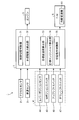
- FIG. 1 is a diagram illustrating a schematic configuration example of a vehicle control system according to the embodiment.
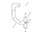
- FIG. 2 is a diagram illustrating a schematic configuration example of the shift device.
- FIG. 3 is a diagram showing the relationship between vehicle speed and acceleration.
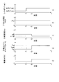
- FIG. 4 is an operation explanatory diagram.
- FIG. 5 is an operation explanatory diagram.
- FIG. 6 is an operation explanatory diagram.
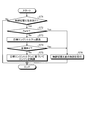
- FIG. 7 is a control flowchart showing a vehicle control method by the vehicle control system according to the embodiment.
- the acceleration in the following embodiment includes not only the acceleration in the direction of accelerating the vehicle but also the acceleration in the direction of decelerating the vehicle.
- FIG. 1 is a diagram illustrating a schematic configuration example of a vehicle control system according to an embodiment.
- FIG. 2 is a diagram illustrating a schematic configuration example of the shift device.
- FIG. 3 is a diagram showing the relationship between vehicle speed and acceleration.
- FIG. 4 is an operation explanatory diagram.
- FIG. 5 is an operation explanatory diagram.
- FIG. 6 is an operation explanatory diagram. 4 to 6 show the shift position ((a) in each figure), the accelerator opening Pa ((b) in each figure), the target shift stage no ((c) in each figure), and the target engine torque To. ((D) of each figure) and each change of the driving force F ((e) of each figure) and a mutual relationship are shown.
- a vehicle on which the driver is boarded includes at least a vehicle control system 1 as shown in FIG.
- the vehicle control system 1 includes an accelerator sensor 2, a vehicle speed sensor 3, a shift device 4, an engine 5, a transmission (hereinafter simply referred to as “T / M”) 6 having an automatic transmission 61, and an ECU 7. It is configured to include.
- T / M transmission
- ECU 7 determines a control amount and a shift instruction based on the required values.
- the vehicle control system 1 controls the engine 5 and the automatic transmission 61 based on the determined control amount and the shift instruction, and causes the vehicle CA to generate an acceleration G [m / s 2 ] corresponding to the required value. . That is, the vehicle control system 1 performs request value demand control.
- Accelerator sensor 2 detects the amount of accelerator operation according to the accelerator operation by the driver.
- the accelerator sensor 2 detects an accelerator opening degree Pa [%] corresponding to an operation of an accelerator pedal (not shown) operated by the driver.
- the accelerator sensor 2 is connected to the ECU 7, a signal related to the accelerator opening degree Pa is output to the ECU 7, and the accelerator opening degree Pa is acquired by the ECU 7 as an input value.
- the acquired accelerator opening degree Pa is used when determining the target driving force Fo.
- the vehicle speed sensor 3 detects the vehicle speed v of the vehicle CA.
- the vehicle speed sensor 3 is connected to the ECU 7, a signal related to the vehicle speed v is output to the ECU 7, and the vehicle speed v is acquired by the ECU 7 as an input value.
- the acquired vehicle speed v is used when determining the target driving force Fo.
- the vehicle speed sensor 3 is not limited to a wheel speed sensor attached to each wheel of the vehicle CA, a sensor that detects the number of rotations of a rotating body in a path from the engine 5 to a driving wheel (not shown), and is represented by GPS.
- the sensor etc. which detect the position data of vehicle CA to be performed may be sufficient.
- the ECU 7 calculates the vehicle speed v based on the output position data.
- the shift device 4 is a shift operation device and a control switching instruction device.
- the shift device 4 instructs the automatic transmission 61 to perform a shift between the gear positions (fixed gear ratio) by the driver's operation.
- the shift device 4 instructs control switching between automatic shift control and manual shift control by the ECU 7 described later by the operation of the driver.
- the shift device 4 includes a first lever passage 41, a second lever passage 42, a shift lever 43, a lever position sensor 44, an M position switch 45, and an upshift switch 46. And a downshift switch 47.
- the shift device 4 is provided in the vicinity of the driver's seat of the vehicle CA, and the shift lever 43 is moved and operated by the driver along a shift pattern constituted by the first lever passage 41 and the second lever passage 42. .
- the first lever passage 41 has, for example, four lever positions, that is, a P (parking) position, an R (reverse) position, an N (neutral) position, and a D (drive) position.
- the second lever passage 42 is formed so as to intersect at a substantially right angle at one end of the first lever passage 41, and is a lever position M (manual) formed at a position intersecting the first lever passage 41.
- a + (upshift) region and a-(downshift) region are provided at both ends of the position and the M position.
- the shift lever 43 is selectively moved to any one of the P position, the R position, the N position, the D position, and the M position by the operation of the driver. If there is no driver's operation, the shift lever 43 is held without moving from the lever position where it is positioned to another lever position. Further, the shift lever 43 can move from the M position to the + region or the ⁇ region. Here, the shift lever 43 automatically returns to the M position even if it moves to the + region or the ⁇ region. That is, even if the shift lever 43 moves to the + region or the ⁇ region by the driver's operation, the shift lever 43 returns to the M position when the driver releases the hand.
- the lever position sensor 44 is provided with respect to the first lever passage 41, and detects position information of the shift lever 43 in the first lever passage 41 as an operation state of the shift lever 43 by the driver.
- the lever position sensor 44 detects at which lever position the shift lever 43 is positioned in the first lever passage 41 by the operation of the driver.
- the lever position sensor 44 is connected to the ECU 7, and a signal related to the lever position is output to the ECU 7.
- the ECU 7 controls the engine 5 and the automatic transmission 61 according to the lever position. Therefore, when the driver operates the shift lever 43 to the D position, the ECU 7 determines that an instruction to switch to vehicle control corresponding to the D position, in the embodiment, automatic shift control, is given according to the driver's will.
- the M position switch 45 is provided with respect to the M position of the second lever passage 42, and detects that the shift lever 43 is positioned at the M position as an operation state of the shift lever 43 by the driver.
- the M position switch 45 is turned on when the shift lever 43 is positioned at the M position by the driver's operation.
- the M position switch 45 is turned off when the shift lever 43 is located in the first lever passage 41 and is kept on as long as it is located in the second lever passage 42.
- the M position switch 45 is connected to the ECU 7, and a signal related to the ON of the M position switch 45 is output to the ECU 7.
- the ECU 7 determines that an instruction to switch to vehicle control corresponding to the M position, in the embodiment, manual shift control is given according to the driver's will. That is, the shift device 4 instructs control switching between automatic shift control and manual shift control by the operation of the driver.
- the current position is displayed on a position indicator (not shown) that operates in conjunction with the shift device 4 so that the driver can recognize the current position.
- the upshift switch 46 is provided for the + region, and detects that the shift lever 43 has moved from the M position to the + region as an operation state of the shift lever 43 by the driver.
- the upshift switch 46 is turned on when the shift lever 43 is moved from the M position to the + region by the operation of the driver.
- the upshift switch 46 is turned off when the shift lever 43 returns from the + region to the M position.
- the upshift switch 46 is connected to the ECU 7, and a signal related to the ON of the upshift switch 46 is output to the ECU 7. Therefore, when the driver operates the shift lever 43 to move from the M position to the + region, the gear position of the automatic transmission 61 is set to be higher than the current gear speed n speed in the manual gear shift control by the driver's will.
- the ECU 7 determines that a shift, that is, an upshift is instructed to the stage n + 1 speed.
- the downshift switch 47 is provided for the ⁇ region, and detects that the shift lever 43 has moved from the M position to the ⁇ region as an operation state of the shift lever 43 by the driver.
- the downshift switch 47 is turned on when the shift lever 43 moves from the M position to the ⁇ region by the driver's operation.
- the downshift switch 47 is turned off when the shift lever 43 returns to the M position from the ⁇ region.
- the downshift switch 47 is connected to the ECU 7, and a signal related to the ON of the downshift switch 47 is output to the ECU 7. Therefore, when the driver operates the shift lever 43 to move from the M position to the ⁇ region, the gear position of the automatic transmission 61 is lower than the current gear speed n speed in the manual gear shift control, according to the driver's will.
- the ECU 7 determines that a gear shift, that is, a downshift, has been instructed to the stage n-1 speed. That is, the shift device 4 instructs a shift by the driver's operation.
- the current range is displayed on a shift range indicator (not shown) that operates in conjunction with the shift device 4 so that the driver can recognize the current range.
- the engine 5 is a power source and is connected to driving wheels (not shown) of the vehicle CA.
- the engine 5 is a heat engine that converts fuel energy into mechanical work by burning the fuel and outputs the mechanical work, and is a piston reciprocating engine.
- the engine 5 includes a fuel injection device (not shown), a throttle valve provided in an intake system (not shown) of the engine 5, a spark plug provided in a combustion chamber (not shown) of the engine 5, various sensors, and the like.
- An output shaft (not shown) of the engine 5 is connected to an input shaft of the T / M 6, and mechanical power output from the engine 5 is transmitted to driving wheels via an automatic transmission 61 of the T / M 6, so that the vehicle CA A driving force F acts on these driving wheels, and an acceleration G is generated in the vehicle CA.
- the engine torque T generated by the engine 5 is controlled based on the control amount, in the embodiment, the target engine torque To determined by the ECU 7.
- the engine 5 is provided with a crank angle sensor (not shown) that detects the rotation angle position of the output shaft (hereinafter referred to as “crank angle”), and a signal related to the crank angle is output to the ECU 7 to thereby detect the crank angle. Is acquired by the ECU 7 as an input value.
- T / M 6 is a power transmission mechanism provided between the engine 5 and the drive wheels, and includes a torque converter including a lock-up clutch (not shown), an automatic transmission 61, various sensors, and the like. ing. These devices are controlled by the ECU 7.
- An output shaft (not shown) of the T / M 6 is connected to the drive wheels.
- the automatic transmission 61 is provided between the torque converter and the drive wheel.
- the automatic transmission 61 transmits the engine torque T to the drive wheels and converts the engine torque T.
- the automatic transmission 61 is a stepped transmission, and the shift is controlled based on a shift instruction.
- the automatic transmission 61 has a plurality of shift speeds, for example, 1st to 6th speeds, and switches the speed ratio to 6 fixed speed ratios corresponding to each speed.
- the automatic transmission 61 is controlled based on the target shift speed no.
- the target shift stage no is determined based on a shift instruction during automatic shift control or a shift instruction during manual shift control.
- the automatic transmission 61 shifts to the high speed side when the target gear stage no is one speed higher than the current speed n, which is the current gear speed (the target speed no may be two speeds). That is, the upshift is performed to change the speed to the (n + 1) th speed, and the target speed no is one speed lower than the current speed n (the target speed no may be the second speed).
- the gear is shifted to the low speed side, that is, downshifted, so that the gear stage becomes n ⁇ 1 speed.
- the engine torque T transmitted to the automatic transmission 61 is converted according to the fixed gear ratio corresponding to the current gear and is transmitted to the drive wheels, so that the driving force F changes according to the gear,
- the acceleration G changes.
- a signal related to the n-th speed that is the current gear position of the automatic transmission 61 is output to the ECU 7, and the actual gear speed nr speed is acquired by the ECU 7 as an input value.
- the ECU 7 is a vehicle control device that performs automatic shift control or manual shift control on the engine 5 and the automatic transmission 61 of the T / M 6. That is, the ECU 7 functions as an engine ECU and a transmission ECU.
- the ECU 7 outputs an injection signal, an ignition signal, an opening signal, etc. to the engine 5 based on the determined target engine torque To, and the fuel supply amount and injection timing of the fuel supplied to the engine 5 by these output signals.
- the engine 5 is controlled such as fuel injection control, ignition plug ignition control (not shown), throttle valve opening control, and the like.
- the ECU 7 outputs various hydraulic control signals and the like to the T / M 6 based on the determined target shift stage no, and performs a shift control of the automatic transmission 61 by these output signals.
- the hardware configuration of the ECU 7 mainly includes a CPU (Central Processing Unit) that performs arithmetic processing, a memory that stores programs and information (RAM such as SRAM, ROM (Read Only Memory) such as EEPROM), and an input / output interface. Since the configuration is the same as that of an ECU mounted on a known vehicle, detailed description thereof is omitted.
- the ECU 7 determines a target driving force Fo that is a required value corresponding to the acceleration G generated in the vehicle CA based on the accelerator opening degree Pa and the vehicle speed v, and sets the target driving force Fo to the target driving force Fo. Based on the target engine torque To and the target shift stage no, the engine 5 is controlled based on the target engine torque To, and the shift of the automatic transmission 61 is controlled based on the target shift stage no.
- the ECU 7 controls the shift of the automatic transmission 61 based on the shift instruction from the shift device 4, and shifts the automatic transmission 61 based on the accelerator opening Pa and the vehicle speed v.
- the target engine torque To is determined so that the change in the acceleration G generated in the vehicle CA becomes larger than that in the automatic shift control, and the engine 5 is controlled based on the target engine torque To.
- the ECU 7 includes a control switching determination unit 71, a target driving force calculation unit 72, a target gear speed calculation unit 73, a target engine torque calculation unit 74, and a switching operation control unit 75.
- a control switching determination unit 71 determines whether a target driving force is required to calculate a target gear speed or a target engine torque.
- a target gear speed calculation unit 73 calculates a target gear speed or a target engine torque.
- a target engine torque calculation unit 74 a switching operation control unit 75.
- Each of the above sections is a process (function) performed by the ECU 7 divided for convenience, and each section may not be divided as a hardware configuration in the ECU 7.
- the control switching determination unit 71 determines control switching between automatic shift control and manual shift control.
- the control switching determination unit 71 determines that the shift lever 43 is in the D position based on a signal related to the lever position from the lever position sensor 44. Further, the control switching determination unit 71 determines that the shift lever 43 is in the M position based on a signal relating to ON from the M position switch 45. Accordingly, the control switching determination unit 71 moves the control from the automatic shift control to the manual shift control or from the manual shift control to the automatic shift control by moving the shift lever 43 from the D position to the M position or from the M position to the D position. It is determined that there is an instruction to switch.
- the target driving force calculation unit 72 calculates the target driving force Fo based on the accelerator opening degree Pa and the vehicle speed v, and determines the target driving force Fo.
- the target driving force calculation unit 72 is based on, for example, an accelerator opening degree Pa, a vehicle speed v, and an exponential function based on Weber-Fechner's law (hereinafter simply referred to as “WF exponential function”).
- WF exponential function based on Weber-Fechner's law
- a target driving force Fo is calculated.
- the target driving force Fo that can cause the vehicle CA to act on the vehicle CA minimum acceleration that can actually be generated in CA
- a target driving force Fo that can cause the vehicle CA to act on a preset maximum acceleration Ga max (a maximum acceleration determined in consideration of the relationship between the accelerator opening degree Pa and the acceleration G) is calculated. It is determined that The target driving force Fo is determined in consideration of the specifications of the vehicle CA, travel resistance, and the like.
- the target shift speed calculation unit 73 determines the target shift speed no based on the shift instruction.
- the target shift speed calculation unit 73 calculates the target shift speed no based on the target drive force Fo calculated by the target drive force calculation unit 72 when the ECU 7 is performing automatic shift control, that is, during automatic shift control.
- the target shift stage no is determined.
- the target shift speed calculation unit 73 calculates the target shift speed no based on, for example, the vehicle speed v and the target driving force Fo during automatic shift control.
- the calculation of the target shift stage no at the time of automatic shift control may use an equation or a shift map.
- an upshift line corresponding to the vehicle speed v and the target driving force Fo (for example, when the vehicle speed v exceeds the upshift line in the increasing direction, n + 1 speed, which is one speed higher than the current shift speed n).
- downshift line (for example, when the vehicle speed v crosses the downshift line in the decreasing direction, the target shift stage no is shifted from the current shift stage n-1 to the target shift stage no. And the like) are configured to give a shift instruction.
- the method of determining the target gear stage no based on the vehicle speed v and the target driving force Fo is known, detailed description thereof is omitted.
- the target shift speed calculation unit 73 is based on a shift instruction from the shift device 4 that reflects the shift intention of the automatic transmission 61 of the driver.
- the shift speed no is calculated, and the target shift speed no is determined.
- the target shift speed calculation unit 73 calculates the target shift speed no based on a signal related to ON of the upshift switch 46 or a signal related to ON of the downshift switch 47 during manual shift control.
- the target engine torque calculation unit 74 determines a target engine torque To that is a control amount based on the accelerator opening degree Pa and the vehicle speed v. In the embodiment, the target engine torque calculation unit 74 calculates the target engine torque To based on the target driving force Fo based on the accelerator opening degree Pa and the vehicle speed v calculated by the target driving force calculation unit 72 during automatic shift control. The target engine torque To is determined. The target engine torque calculation unit 74 calculates the target engine torque To based on, for example, the target drive force Fo and the actual gear stage na speed of the automatic transmission 61 calculated by the target gear stage calculation unit 73 during automatic shift control. .
- the target engine torque calculation unit 74 calculates the target engine torque To so that the target driving force Fo can be generated at the actual shift speed na speed of the automatic transmission 61 during the automatic shift control.
- the EUC 7 controls the engine 5 so that the engine torque T generated by the engine 5 becomes the target engine torque To.
- the target engine torque calculation unit 74 determines a target engine torque To that is a control amount based on the accelerator opening degree Pa and the vehicle speed v during manual shift control.
- the target engine torque calculation unit 74 is configured to calculate the acceleration G generated in the vehicle CA by the shift of the automatic transmission 61 based on the target driving force Fo based on the accelerator opening Pa and the vehicle speed v during manual shift control.
- the target engine torque To is calculated to determine the target engine torque To so that the change is greater than that during automatic shift control.
- the target engine torque calculation unit 74 calculates the target engine torque To based on, for example, the target drive force Fo and the actual shift speed nr speed of the automatic transmission 61 calculated by the target shift speed calculation unit 73 during manual shift control. .
- the target engine torque To at the time of the manual shift control is the difference Fa ⁇ Fb between the driving force Fa acting on the vehicle CA after the shift of the automatic transmission 61 at the time of the manual shift control and the drive force Fb before the shift. It is calculated so as to be larger than the difference Fc ⁇ Fd between the driving force Fc after the shifting and the driving force Fd before the shifting.
- the target engine torque calculation unit 74 decreases when, for example, the driving force F in the state where the accelerator opening degree Pa and the vehicle speed v are the same shifts from the shift stage n speed to the n + 1 speed after the upshift.
- the target engine torque To is calculated so as to increase when shifting from the nth speed to the n-1 speed after downshifting.
- the target engine torque To at the time of manual shift control becomes smaller when the acceleration G in the state where the accelerator opening degree Pa and the vehicle speed v are the same shifts from the shift stage n speed to the n + 1 speed after the upshift.
- the target engine torque To is calculated so as to increase when shifting from the first speed to the n-1th speed after the downshift.
- the target engine torque calculation unit 74 calculates the target engine torque To so that the maximum acceleration Gm max, which is the acceleration G when the accelerator is fully opened, differs for each gear position.
- the target engine torque calculation unit 74 sets the target engine torque so that the minimum acceleration Gm mim, which is the acceleration G when the accelerator is fully opened, becomes the minimum acceleration that can be actually generated in the vehicle CA by the engine 5 and T / M 6. To is calculated.
- the target engine torque calculation unit 74 for example, the target driving force Fo calculated at the time of manual shift control or the target engine torque To calculated based on the target driving force Fo is changed according to the actual shift speed nr. Correction is made so that the change in the acceleration G generated in CA becomes larger than that in the automatic shift control.
- the change in the acceleration G generated in the vehicle CA due to the shift of the automatic transmission 61 is greater than during automatic shift control.
- the maximum acceleration Ga max during the automatic shift control does not change regardless of the shift of the automatic transmission 61.
- the maximum acceleration Gm max during the manual shift control changes due to the shift of the automatic transmission 61.
- the acceleration G generated on the vehicle CA is between the accelerator is fully closed to fully open throttle, changes minimum acceleration Ga mim, the Gm mim maximum acceleration Ga max, until Gm max. Accordingly, the width of the acceleration G corresponding to the driver's accelerator operation during the automatic shift control does not change at an arbitrary vehicle speed v (La shown in the figure).
- the width of the acceleration G corresponding to the driver's accelerator operation during the manual shift control changes according to the shift stage at an arbitrary vehicle speed v (Lm n , Lm n-1 shown in the figure). That is, at the time of manual shift control, the acceleration G generated in the vehicle CA changes for each shift stage with the accelerator opening Pa and the vehicle speed v being the same. If the same control as the automatic shift control is performed in the manual shift control, the change in the acceleration G generated in the vehicle CA by the shift of the automatic transmission 61 does not change in either the manual shift control or the automatic shift control. However, as described above, in the manual shift control, the method of generating the acceleration G with respect to the driver's accelerator operation is different for each shift stage as compared with the automatic shift control. The operability can be improved and the operability can be improved.
- the switching operation control unit 75 controls the switching operation for performing the actual control switching after the control switching instruction.
- the switching operation control unit 75 performs control of the engine 5 and the automatic transmission 61 after the control switching instruction by the driver based on the signal related to the lever position or the signal related to the ON of the M position switch 45. It controls a switching operation which is an operation of switching to any one of the shift control or switching from manual shift control to automatic shift control.
- the switching operation control unit 75 changes the switching operation according to the operation of the accelerator.
- the target engine torque To is changed between the control amount before switching and the control amount after switching in accordance with the operation of the accelerator.
- the pre-switching control amount is a control amount at the time of control before the control switching instruction, and in the embodiment, is determined in the control before the control switching (automatic shift control or manual shift control) by the control switching instruction. This refers to the pre-switching torque Toa that is the target engine torque To.
- the control amount after switching is a control amount at the time of control after the control switching instruction.
- control after control switching by the control switching instruction (manual shift control if the control before switching is automatic shift control, This is the post-switching torque Tob, which is the target engine torque To determined in automatic shift control if the control shift is before manual shift control.
- the switching operation control unit 75 calculates the target engine torque To during the switching operation.
- the target engine torque To during the switching operation changes in torque, that is, a control amount, from the pre-switching torque Toa to the post-switching torque Tob according to the accelerator operation.
- the switching operation control unit 75 changes the torque from the pre-switching torque Toa to the post-switching torque Tob more slowly when the accelerator is on than when the accelerator is off.
- the switching operation control unit 75 changes the accelerator opening Pa from the instructed accelerator opening Pa1 that is the accelerator opening Pa at the time of control switching to the predetermined accelerator opening Pax.
- the switching operation control unit 75 for example, the current accelerator opening Pa, the instruction accelerator opening Pa1, the predetermined accelerator opening Pax, the pre-switching torque To1, the post-switching torque Tox, and the following equation (1)
- the target engine torque To during the switching operation is calculated, and the engine 5 is controlled based on the calculated target engine torque To.
- the predetermined accelerator opening degree Pax is determined based on the instructed accelerator opening degree Pa1, and when the accelerator opening degree Pa increases due to the driver's accelerator operation, and when the accelerator opening degree Pa decreases. Therefore, it can be set to either plus or minus.
- To (Tox ⁇ To1) ⁇ ((Pa ⁇ Pa1) / Pax) + To1 (1)
- the control switching is performed from the automatic shift control to the manual shift control immediately after the control switching instruction, and the virtual torque in the case of the instructed accelerator opening Pa1 from the pre-switching torque To1 during the manual shift control.
- the target engine torque To will change until Tom1 (two-dot line shown in the figure). Therefore, when the control switching is performed from the automatic transmission control to the manual transmission control immediately after the control switching instruction, the driving force F changes according to the change in the target engine torque To, and the accelerator opening Pa is constant and the automatic transmission.
- the gear 61 is not shifting, a shock may occur in the vehicle CA, which may cause the driver to feel uncomfortable.
- the pre-switching torque To1 is maintained, so that the driver can be prevented from feeling uncomfortable.
- the shift of the automatic transmission 61 based on the shift instruction in the manual shift control is executable immediately after the control switch instruction.
- the switching operation control unit 75 (t3 in the figure) until the change becomes the predetermined accelerator opening degree Pax. ), The engine 5 is controlled based on the target engine torque To during the switching operation.
- the switching operation control unit 75 terminates the switching operation, performs control switching from automatic transmission control to manual transmission control, and then performs manual transmission control. Therefore, for example, when the accelerator opening degree Pa further increases from the predetermined accelerator opening degree Pax, the engine 5 is controlled based on the target engine torque To in the case of the accelerator opening degree Pa at the time of manual shift control.
- the switching operation control unit 75 gradually changes the target engine torque To from the pre-switching torque to the post-switching torque while the accelerator opening degree Pa is changing, that is, while the driving force F is changing. Therefore, since the control switching can be performed while the acceleration G generated in the vehicle CA is changing, in a state where the accelerator opening degree Pa does not change, that is, in a state where no step is generated in the driving force F for the driver. The occurrence of a shock or the like due to control switching can be suppressed, and the driver can be prevented from feeling uncomfortable. Note that the switching operation control unit 75 performs the same switching operation as described above even when the control switching is performed from the manual shift control to the automatic shift control.
- the switching operation control unit 75 performs a switching operation in which the target engine torque To is set to the post-switching torque To immediately after the control switching instruction when the accelerator is off at the time of the control switching instruction, that is, the accelerator opening degree Pa is 0%. That is, the switching operation control unit 75 immediately switches control based on the control switching instruction if the accelerator is off at the time of the control switching instruction. For example, when control switching is performed from manual shift control to automatic shift control, if the accelerator is off at the time of control switching instruction, the switching operation ends immediately after the control switching instruction, and at the time of control switching instruction at the time of manual shift control The target engine torque To in the case of the accelerator opening degree Pa is calculated, and the engine 5 is controlled based on the calculated target engine torque To.
- the switching operation control unit 75 when the shift of the automatic transmission 61 is performed when the accelerator is on, the switching operation control unit 75 performs a switching operation for setting the target engine torque To to the post-switching torque To immediately after the shifting. Do. In other words, the switching operation control unit 75 immediately switches control based on the control switching instruction when the accelerator is on at the time of the control switching instruction and the automatic transmission 61 is shifted after the control switching instruction.
- the switching operation control unit 75 keeps the accelerator opening degree Pa at the instructed accelerator opening degree Pa2, and changes the shift stage of the automatic transmission 61 from the n-th speed to the (n ⁇ 1) based on the shift instruction by the driver operating the shift lever 43.
- shifting to a high speed that is, downshifting (t2 in the figure)
- the automatic shift control is immediately switched to the manual shift control, and at the time of the manual shift control, the shift stage is n-1 speed and the instructed accelerator opening Pa2.
- the engine 5 is controlled based on the target engine torque To3 in the case.
- the driver has a desire to change the driving force F and change the acceleration G. Therefore, when the driver seeks a change in the driving force F due to the shift of the automatic transmission 61, the driving force F can be changed to reflect the driver's will, which makes the driver feel uncomfortable. Can be suppressed.
- the switching operation control unit 75 changes the speed of the automatic transmission 61 from n-speed to n + 1-speed based on the shift instruction in the automatic shift control while the accelerator opening Pa remains the instruction-time accelerator opening Pa2. (T2 in the figure), the manual shift control is immediately switched to the automatic shift control, and the engine 5 is controlled based on the target engine torque To5 in the case of the command accelerator opening degree Pa2 during the automatic shift control.
- FIG. 7 is a control flowchart showing a vehicle control method by the vehicle control system according to the embodiment. Since the method for controlling the engine 5 and the automatic transmission 61 by the automatic shift control or the manual shift control has been described above, the description thereof is omitted here. Hereinafter, the control method of the switching operation is executed every predetermined control cycle. Moreover, the control flow shown in the figure is an example, and the order of each process is not limited.
- control switching determination unit 71 of the ECU 7 determines whether or not there is a control switching instruction (step ST1).
- the control switching determination unit 71 determines whether there is a control switching instruction for switching control between automatic shift control and manual shift control.
- Step ST2 when the switching operation control unit 75 of the ECU 7 determines that there is a control switching instruction (Yes in Step ST1), it determines whether or not the accelerator opening degree Pa is 0 (Step ST2).
- the switching operation control unit 75 determines whether or not the accelerator is off at the time of the control switching instruction. Note that if the switching operation control unit 75 determines that there is no control switching instruction (No in step ST1), it ends the current control cycle and shifts to the next control cycle.
- step ST3 when the switching operation control unit 75 determines that the accelerator opening degree Pa is not 0 (No in step ST2), it calculates a target engine torque To during the switching operation (step ST3). Since the calculation method of the target engine torque To during the switching operation has been described above, the description is omitted here.
- the switching operation control unit 75 determines whether or not the automatic transmission 61 has been shifted (step ST4).
- the switching operation control unit 75 determines whether or not the automatic transmission 61 has been shifted after the control switching instruction, based on the shift instruction in the manual shift control or the shift instruction in the automatic shift control.
- Step ST5 the current control cycle is terminated, and the process proceeds to the next control cycle. Therefore, the torque change from the pre-switching torque Toa to the post-switching torque Tob is performed while the accelerator opening degree Pa is changing.
- Step ST6 the switching operation control unit 75 determines that the accelerator opening degree Pa is 0 (Yes in Step ST2) or determines that the shift of the automatic transmission 61 is performed (Yes in Step ST4)
- the switching operation control unit 75 performs the control after the control switching. Control is executed (step ST6), the current control cycle is terminated, and the next control cycle is started. Therefore, the control is immediately switched immediately after the automatic transmission 61 is shifted.
- the target engine is set such that the change in the acceleration G generated in the vehicle CA due to the shift of the automatic transmission 61 is greater than that during the automatic shift control. Since the torque To is determined and the engine 5 is controlled based on the determined target engine torque To, it is possible to improve the controllability of the vehicle during manual shift control. In addition, since the switching operation for performing actual control switching is changed according to the accelerator operation after the control switching instruction, it is possible to suppress the driver from feeling uncomfortable.
- the target engine torque To in the manual shift control is calculated based on the target driving force Fo, but the present invention is not limited to this, and is directly based on the accelerator opening degree Pa and the vehicle speed v.
- the target engine torque To may be calculated. That is, the target engine torque To at the time of manual shift control may be obtained by a conventional method for calculating the target engine torque To in the vehicle CA. In this case, during the automatic shift control, the target engine torque To is calculated so that the change in the acceleration G generated in the vehicle CA due to the shift of the automatic transmission 61 becomes smaller than during the manual shift control.
- the automatic transmission 61 may be forcibly changed when the control is switched.
- a control switch when a control switch is performed from an automatic shift control to a manual shift control according to a control switch instruction, an upshift or a downshift (refer to a one-dot chain line) may be forcibly performed.
- the switching operation control unit 75 performs the switching operation while the accelerator opening degree Pa is changing when the accelerator is on. Accordingly, in the switching operation, the control shift from the automatic shift control to the manual shift control is not performed immediately after the control switch instruction, and the pre-switching torque To1 in the case of the command accelerator opening degree Pa1 is maintained during the automatic shift control.
- the target driving force Fo is used as the required value corresponding to the acceleration G generated in the vehicle CA, but the present invention is not limited to this and may be the target acceleration Gx.
- the target engine torque To and the target shift stage no are determined based on the target acceleration Gx.
- the vehicle control system and the vehicle control method are vehicle controls that determine a required value corresponding to the acceleration acting on the vehicle based on the accelerator operation amount according to the accelerator operation by the driver and the vehicle speed of the vehicle.
- the present invention is useful for a system and a vehicle control method, and is particularly suitable for sufficiently realizing acceleration in accordance with a driver's sensitivity by determining an optimum target acceleration with respect to a driver's accelerator operation amount.
Landscapes
- Engineering & Computer Science (AREA)
- Mechanical Engineering (AREA)
- Chemical & Material Sciences (AREA)
- Combustion & Propulsion (AREA)
- Transportation (AREA)
- Automation & Control Theory (AREA)
- General Engineering & Computer Science (AREA)
- Human Computer Interaction (AREA)
- Control Of Transmission Device (AREA)
- Control Of Driving Devices And Active Controlling Of Vehicle (AREA)
- Control Of Vehicle Engines Or Engines For Specific Uses (AREA)
Abstract
Description
To=(Tox-To1)×((Pa-Pa1)/Pax)+To1…(1)
2 アクセルセンサ
3 車速センサ
4 シフト装置
41 第1レバー通路
42 第2レバー通路
43 シフトレバー
44 レバーポジションセンサ
45 Mポジションスイッチ
46 アップシフトスイッチ
47 ダウンシフトスイッチ
5 エンジン
6 トランスミッション(T/M)
7 ECU
71 制御切替判断部
72 目標駆動力算出部
73 目標変速段算出部
74 目標エンジントルク算出部
75 切替動作制御部
Claims (6)
- 車両の駆動輪に連結され、制御量に基づいて制御される動力源と、
前記動力源と前記駆動輪との間に設けられ、変速指示に基づいて変速が制御される自動変速機と、
運転者の操作により変速を指示する変速操作装置と、
前記運転者によるアクセルの操作に応じたアクセル操作量および車速に基づいて決定される加速度に対応する要求値に基づいて決定される前記制御量および前記変速指示に基づいて前記動力源および前記自動変速機をそれぞれ制御する自動変速制御と、前記変速操作装置からの前記変速指示に基づいて前記自動変速機を制御するとともに、前記アクセル操作量および前記車速に基づいて、前記変速により前記車両に発生する加速度の変化が前記自動変速制御時よりも大きくなるように決定される前記制御量に基づいて前記動力源を制御する手動変速制御とのいずれかの制御を行う車両制御装置と、
前記運転者の操作により前記自動変速制御と前記手動変速制御との間での制御切替えを指示する制御切替え指示装置と、
を備え、
前記車両制御装置は、前記制御切替えの指示後に、実際の前記制御切替えを行う切替動作を前記アクセルの操作に応じて変化させることを特徴とする車両制御システム。 - 前記切替動作は、前記制御量を前記制御切替え前の制御時における前記制御量である切替前制御量から前記制御切替え後の制御時における前記制御量である切替後制御量に制御量変化させることを含むものであり、前記制御量変化を前記アクセルのオン時に、オフ時よりも緩やかにする請求項1に記載の車両制御システム。
- 前記アクセルのオン時における前記切替動作は、前記アクセル操作量の変化中に行われる請求項2に記載の車両制御システム。
- 前記切替動作は、前記制御切替えの指示時に前記アクセルがオフであると、前記制御切替えの指示直後に前記制御量を前記切替後制御量とする請求項2または3に記載の車両制御システム。
- 前記切替動作は、前記アクセルのオン時において前記自動変速機の変速が行われると、前記変速直後に前記制御量を前記切替後制御量とする請求項1に記載の車両制御システム。
- 運転者によるアクセルの操作に応じたアクセル操作量および車両の車速に基づいて決定される加速度に対応する要求値に基づいて決定される制御量に基づいて、前記車両の駆動輪に連結される動力源を制御し、前記要求値に基づいて決定される変速指示に基づいて、前記駆動輪との間に設けられ、自動変速機の変速を制御する自動変速制御と、
前記運転者の操作により前記自動変速機に変速を指示する変速操作装置からの前記変速指示に基づいて前記自動変速機の変速を制御するとともに、前記アクセル操作量および前記車速に基づいて、前記変速により前記車両に発生する加速度の変化が前記自動変速制御時よりも大きくなるように決定される前記制御量に基づいて前記動力源を制御する手動変速制御と、
のいずれかにより前記動力源及び前記自動変速機を制御する車両制御方法であって、
前記運転者の操作に基づいて前記自動変速制御と前記手動変速制御との間での制御切替えが指示された後に、実際の前記制御切替えを行う切替動作を前記アクセルの操作に応じて変化させることを特徴とする車両制御方法。
Priority Applications (4)
| Application Number | Priority Date | Filing Date | Title |
|---|---|---|---|
| US13/580,834 US8485942B2 (en) | 2010-02-25 | 2010-02-25 | Vehicle control system and vehicle control method |
| JP2012501583A JP5278590B2 (ja) | 2010-02-25 | 2010-02-25 | 車両制御システムおよび車両制御方法 |
| CN201080064845.7A CN102782295B (zh) | 2010-02-25 | 2010-02-25 | 车辆控制系统及车辆控制方法 |
| PCT/JP2010/052994 WO2011104852A1 (ja) | 2010-02-25 | 2010-02-25 | 車両制御システムおよび車両制御方法 |
Applications Claiming Priority (1)
| Application Number | Priority Date | Filing Date | Title |
|---|---|---|---|
| PCT/JP2010/052994 WO2011104852A1 (ja) | 2010-02-25 | 2010-02-25 | 車両制御システムおよび車両制御方法 |
Publications (1)
| Publication Number | Publication Date |
|---|---|
| WO2011104852A1 true WO2011104852A1 (ja) | 2011-09-01 |
Family
ID=44506297
Family Applications (1)
| Application Number | Title | Priority Date | Filing Date |
|---|---|---|---|
| PCT/JP2010/052994 Ceased WO2011104852A1 (ja) | 2010-02-25 | 2010-02-25 | 車両制御システムおよび車両制御方法 |
Country Status (4)
| Country | Link |
|---|---|
| US (1) | US8485942B2 (ja) |
| JP (1) | JP5278590B2 (ja) |
| CN (1) | CN102782295B (ja) |
| WO (1) | WO2011104852A1 (ja) |
Cited By (3)
| Publication number | Priority date | Publication date | Assignee | Title |
|---|---|---|---|---|
| WO2014181247A1 (en) | 2013-05-09 | 2014-11-13 | Sasol Technology (Proprietary) Limited | Oligomerisation of ethylene to mixtures of 1-hexene and 1-octene |
| JP2018177082A (ja) * | 2017-04-18 | 2018-11-15 | スズキ株式会社 | 車両の制御装置 |
| US11225923B2 (en) * | 2020-01-22 | 2022-01-18 | Toyota Jidosha Kabushiki Kaisha | Controller and control method for internal combustion engine |
Families Citing this family (7)
| Publication number | Priority date | Publication date | Assignee | Title |
|---|---|---|---|---|
| KR101327098B1 (ko) * | 2012-09-24 | 2013-11-22 | 현대자동차주식회사 | 고객 감성 기반 변속감 정량화 평가 방법 |
| CN104653760B (zh) * | 2015-02-09 | 2017-02-22 | 长城汽车股份有限公司 | Amt变速器换挡控制方法、控制装置及amt变速器 |
| JP6413964B2 (ja) * | 2015-07-17 | 2018-10-31 | トヨタ自動車株式会社 | クルーズコントロール装置 |
| JP6292215B2 (ja) * | 2015-12-09 | 2018-03-14 | トヨタ自動車株式会社 | 内燃機関の制御装置 |
| DE102016001399B4 (de) * | 2016-02-06 | 2020-09-17 | Audi Ag | Verfahren und Vorrichtung zum Betreiben einer Antriebsvorrichtung, Antriebsvorrichtung |
| JP6748059B2 (ja) * | 2017-12-28 | 2020-08-26 | 本田技研工業株式会社 | 車両の制御装置 |
| CN112498548B (zh) * | 2021-01-29 | 2021-06-22 | 赛格威科技有限公司 | 全地形车的降噪控制方法和降噪控制系统 |
Citations (2)
| Publication number | Priority date | Publication date | Assignee | Title |
|---|---|---|---|---|
| JPH07174221A (ja) * | 1993-03-03 | 1995-07-11 | Toyota Motor Corp | 自動変速機の制御装置 |
| JP2000002328A (ja) * | 1998-04-14 | 2000-01-07 | Nissan Motor Co Ltd | 自動変速機の変速モ―ド切替制御装置 |
Family Cites Families (7)
| Publication number | Priority date | Publication date | Assignee | Title |
|---|---|---|---|---|
| JP2683647B2 (ja) | 1986-07-08 | 1997-12-03 | マツダ株式会社 | エンジンの制御装置 |
| JP3176522B2 (ja) * | 1995-02-06 | 2001-06-18 | 本田技研工業株式会社 | 車両用自動変速機の制御装置 |
| JP3551776B2 (ja) | 1998-08-10 | 2004-08-11 | 日産自動車株式会社 | 車両の駆動力制御装置 |
| JP2002327838A (ja) | 2001-04-27 | 2002-11-15 | Denso Corp | 自動変速機の変速制御方法 |
| JP4244879B2 (ja) | 2004-08-06 | 2009-03-25 | トヨタ自動車株式会社 | 車両用自動変速機の変速制御装置 |
| DE102004057724A1 (de) * | 2004-11-30 | 2006-06-01 | Bayerische Motoren Werke Ag | Vorrichtung zum Steuern eines automatisch schaltenden Getriebes |
| JP4188360B2 (ja) * | 2005-10-31 | 2008-11-26 | 本田技研工業株式会社 | 自動変速機の変速制御装置 |
-
2010
- 2010-02-25 JP JP2012501583A patent/JP5278590B2/ja not_active Expired - Fee Related
- 2010-02-25 CN CN201080064845.7A patent/CN102782295B/zh not_active Expired - Fee Related
- 2010-02-25 WO PCT/JP2010/052994 patent/WO2011104852A1/ja not_active Ceased
- 2010-02-25 US US13/580,834 patent/US8485942B2/en not_active Expired - Fee Related
Patent Citations (2)
| Publication number | Priority date | Publication date | Assignee | Title |
|---|---|---|---|---|
| JPH07174221A (ja) * | 1993-03-03 | 1995-07-11 | Toyota Motor Corp | 自動変速機の制御装置 |
| JP2000002328A (ja) * | 1998-04-14 | 2000-01-07 | Nissan Motor Co Ltd | 自動変速機の変速モ―ド切替制御装置 |
Cited By (3)
| Publication number | Priority date | Publication date | Assignee | Title |
|---|---|---|---|---|
| WO2014181247A1 (en) | 2013-05-09 | 2014-11-13 | Sasol Technology (Proprietary) Limited | Oligomerisation of ethylene to mixtures of 1-hexene and 1-octene |
| JP2018177082A (ja) * | 2017-04-18 | 2018-11-15 | スズキ株式会社 | 車両の制御装置 |
| US11225923B2 (en) * | 2020-01-22 | 2022-01-18 | Toyota Jidosha Kabushiki Kaisha | Controller and control method for internal combustion engine |
Also Published As
| Publication number | Publication date |
|---|---|
| JPWO2011104852A1 (ja) | 2013-06-17 |
| US8485942B2 (en) | 2013-07-16 |
| JP5278590B2 (ja) | 2013-09-04 |
| CN102782295B (zh) | 2014-03-26 |
| US20120316032A1 (en) | 2012-12-13 |
| CN102782295A (zh) | 2012-11-14 |
Similar Documents
| Publication | Publication Date | Title |
|---|---|---|
| JP5278590B2 (ja) | 車両制御システムおよび車両制御方法 | |
| US9586576B2 (en) | Hybrid vehicle control device | |
| JP6359108B2 (ja) | 自動変速機の制御装置 | |
| JP5407979B2 (ja) | 自動変速機の変速制御装置 | |
| CN106065941A (zh) | 车辆的控制装置 | |
| JP2010230139A (ja) | 自動車の制御方法 | |
| JP4639834B2 (ja) | 自動変速機の制御装置 | |
| JP2008025709A (ja) | 車両用自動変速機の制御装置 | |
| JP2013245590A (ja) | 車両の変速制御装置 | |
| JP4702099B2 (ja) | 変速指示装置 | |
| JP4821706B2 (ja) | 車両の制御装置 | |
| US10589744B2 (en) | Shifting control method for vehicle with dual clutch transmission | |
| JP2009275558A (ja) | 車両の制御装置および制御方法 | |
| JP4848743B2 (ja) | 自動変速機の制御装置 | |
| JP6196905B2 (ja) | 車両の変速制御装置 | |
| JP6213276B2 (ja) | 変速制御装置 | |
| JP2008215198A (ja) | 内燃機関の制御装置および制御方法 | |
| JP2007100924A (ja) | 車両用変速機制御装置 | |
| JP2008115945A (ja) | 車両の制御装置、制御方法、その方法を実現するプログラムおよびそのプログラムを記録した記録媒体 | |
| JP2009264548A (ja) | 駆動力制御装置および駆動力制御方法 | |
| JP2005219529A (ja) | 車両用走行制御装置 | |
| JP2016031048A (ja) | 車両の制御装置 | |
| JP2006300141A (ja) | パワートレーンの制御装置 | |
| JP2024154340A (ja) | エンジン回転速度計の表示制御装置 | |
| JP2008215265A (ja) | 車両の表示装置 |
Legal Events
| Date | Code | Title | Description |
|---|---|---|---|
| WWE | Wipo information: entry into national phase |
Ref document number: 201080064845.7 Country of ref document: CN |
|
| 121 | Ep: the epo has been informed by wipo that ep was designated in this application |
Ref document number: 10846517 Country of ref document: EP Kind code of ref document: A1 |
|
| WWE | Wipo information: entry into national phase |
Ref document number: 2012501583 Country of ref document: JP |
|
| WWE | Wipo information: entry into national phase |
Ref document number: 13580834 Country of ref document: US |
|
| NENP | Non-entry into the national phase |
Ref country code: DE |
|
| 122 | Ep: pct application non-entry in european phase |
Ref document number: 10846517 Country of ref document: EP Kind code of ref document: A1 |