WO2011102493A1 - 液晶表示装置及びその製造方法、並びに画像表示装置 - Google Patents
液晶表示装置及びその製造方法、並びに画像表示装置 Download PDFInfo
- Publication number
- WO2011102493A1 WO2011102493A1 PCT/JP2011/053579 JP2011053579W WO2011102493A1 WO 2011102493 A1 WO2011102493 A1 WO 2011102493A1 JP 2011053579 W JP2011053579 W JP 2011053579W WO 2011102493 A1 WO2011102493 A1 WO 2011102493A1
- Authority
- WO
- WIPO (PCT)
- Prior art keywords
- film
- refractive index
- rth
- liquid crystal
- layer
- Prior art date
- Legal status (The legal status is an assumption and is not a legal conclusion. Google has not performed a legal analysis and makes no representation as to the accuracy of the status listed.)
- Ceased
Links
Classifications
-
- G—PHYSICS
- G02—OPTICS
- G02B—OPTICAL ELEMENTS, SYSTEMS OR APPARATUS
- G02B5/00—Optical elements other than lenses
- G02B5/30—Polarising elements
- G02B5/3025—Polarisers, i.e. arrangements capable of producing a definite output polarisation state from an unpolarised input state
- G02B5/3033—Polarisers, i.e. arrangements capable of producing a definite output polarisation state from an unpolarised input state in the form of a thin sheet or foil, e.g. Polaroid
-
- G—PHYSICS
- G02—OPTICS
- G02F—OPTICAL DEVICES OR ARRANGEMENTS FOR THE CONTROL OF LIGHT BY MODIFICATION OF THE OPTICAL PROPERTIES OF THE MEDIA OF THE ELEMENTS INVOLVED THEREIN; NON-LINEAR OPTICS; FREQUENCY-CHANGING OF LIGHT; OPTICAL LOGIC ELEMENTS; OPTICAL ANALOGUE/DIGITAL CONVERTERS
- G02F1/00—Devices or arrangements for the control of the intensity, colour, phase, polarisation or direction of light arriving from an independent light source, e.g. switching, gating or modulating; Non-linear optics
- G02F1/01—Devices or arrangements for the control of the intensity, colour, phase, polarisation or direction of light arriving from an independent light source, e.g. switching, gating or modulating; Non-linear optics for the control of the intensity, phase, polarisation or colour
- G02F1/13—Devices or arrangements for the control of the intensity, colour, phase, polarisation or direction of light arriving from an independent light source, e.g. switching, gating or modulating; Non-linear optics for the control of the intensity, phase, polarisation or colour based on liquid crystals, e.g. single liquid crystal display cells
- G02F1/133—Constructional arrangements; Operation of liquid crystal cells; Circuit arrangements
- G02F1/1333—Constructional arrangements; Manufacturing methods
- G02F1/1335—Structural association of cells with optical devices, e.g. polarisers or reflectors
- G02F1/13363—Birefringent elements, e.g. for optical compensation
-
- G—PHYSICS
- G02—OPTICS
- G02B—OPTICAL ELEMENTS, SYSTEMS OR APPARATUS
- G02B1/00—Optical elements characterised by the material of which they are made; Optical coatings for optical elements
- G02B1/10—Optical coatings produced by application to, or surface treatment of, optical elements
- G02B1/11—Anti-reflection coatings
-
- G—PHYSICS
- G02—OPTICS
- G02B—OPTICAL ELEMENTS, SYSTEMS OR APPARATUS
- G02B5/00—Optical elements other than lenses
- G02B5/30—Polarising elements
-
- G—PHYSICS
- G02—OPTICS
- G02F—OPTICAL DEVICES OR ARRANGEMENTS FOR THE CONTROL OF LIGHT BY MODIFICATION OF THE OPTICAL PROPERTIES OF THE MEDIA OF THE ELEMENTS INVOLVED THEREIN; NON-LINEAR OPTICS; FREQUENCY-CHANGING OF LIGHT; OPTICAL LOGIC ELEMENTS; OPTICAL ANALOGUE/DIGITAL CONVERTERS
- G02F1/00—Devices or arrangements for the control of the intensity, colour, phase, polarisation or direction of light arriving from an independent light source, e.g. switching, gating or modulating; Non-linear optics
- G02F1/01—Devices or arrangements for the control of the intensity, colour, phase, polarisation or direction of light arriving from an independent light source, e.g. switching, gating or modulating; Non-linear optics for the control of the intensity, phase, polarisation or colour
- G02F1/13—Devices or arrangements for the control of the intensity, colour, phase, polarisation or direction of light arriving from an independent light source, e.g. switching, gating or modulating; Non-linear optics for the control of the intensity, phase, polarisation or colour based on liquid crystals, e.g. single liquid crystal display cells
- G02F1/133—Constructional arrangements; Operation of liquid crystal cells; Circuit arrangements
- G02F1/1333—Constructional arrangements; Manufacturing methods
- G02F1/1335—Structural association of cells with optical devices, e.g. polarisers or reflectors
- G02F1/13363—Birefringent elements, e.g. for optical compensation
- G02F1/133634—Birefringent elements, e.g. for optical compensation the refractive index Nz perpendicular to the element surface being different from in-plane refractive indices Nx and Ny, e.g. biaxial or with normal optical axis
-
- G—PHYSICS
- G03—PHOTOGRAPHY; CINEMATOGRAPHY; ANALOGOUS TECHNIQUES USING WAVES OTHER THAN OPTICAL WAVES; ELECTROGRAPHY; HOLOGRAPHY
- G03B—APPARATUS OR ARRANGEMENTS FOR TAKING PHOTOGRAPHS OR FOR PROJECTING OR VIEWING THEM; APPARATUS OR ARRANGEMENTS EMPLOYING ANALOGOUS TECHNIQUES USING WAVES OTHER THAN OPTICAL WAVES; ACCESSORIES THEREFOR
- G03B21/00—Projectors or projection-type viewers; Accessories therefor
- G03B21/14—Details
- G03B21/20—Lamp housings
- G03B21/2073—Polarisers in the lamp house
-
- G—PHYSICS
- G03—PHOTOGRAPHY; CINEMATOGRAPHY; ANALOGOUS TECHNIQUES USING WAVES OTHER THAN OPTICAL WAVES; ELECTROGRAPHY; HOLOGRAPHY
- G03B—APPARATUS OR ARRANGEMENTS FOR TAKING PHOTOGRAPHS OR FOR PROJECTING OR VIEWING THEM; APPARATUS OR ARRANGEMENTS EMPLOYING ANALOGOUS TECHNIQUES USING WAVES OTHER THAN OPTICAL WAVES; ACCESSORIES THEREFOR
- G03B35/00—Stereoscopic photography
- G03B35/18—Stereoscopic photography by simultaneous viewing
-
- G—PHYSICS
- G03—PHOTOGRAPHY; CINEMATOGRAPHY; ANALOGOUS TECHNIQUES USING WAVES OTHER THAN OPTICAL WAVES; ELECTROGRAPHY; HOLOGRAPHY
- G03B—APPARATUS OR ARRANGEMENTS FOR TAKING PHOTOGRAPHS OR FOR PROJECTING OR VIEWING THEM; APPARATUS OR ARRANGEMENTS EMPLOYING ANALOGOUS TECHNIQUES USING WAVES OTHER THAN OPTICAL WAVES; ACCESSORIES THEREFOR
- G03B35/00—Stereoscopic photography
- G03B35/18—Stereoscopic photography by simultaneous viewing
- G03B35/26—Stereoscopic photography by simultaneous viewing using polarised or coloured light separating different viewpoint images
-
- G—PHYSICS
- G02—OPTICS
- G02F—OPTICAL DEVICES OR ARRANGEMENTS FOR THE CONTROL OF LIGHT BY MODIFICATION OF THE OPTICAL PROPERTIES OF THE MEDIA OF THE ELEMENTS INVOLVED THEREIN; NON-LINEAR OPTICS; FREQUENCY-CHANGING OF LIGHT; OPTICAL LOGIC ELEMENTS; OPTICAL ANALOGUE/DIGITAL CONVERTERS
- G02F1/00—Devices or arrangements for the control of the intensity, colour, phase, polarisation or direction of light arriving from an independent light source, e.g. switching, gating or modulating; Non-linear optics
- G02F1/01—Devices or arrangements for the control of the intensity, colour, phase, polarisation or direction of light arriving from an independent light source, e.g. switching, gating or modulating; Non-linear optics for the control of the intensity, phase, polarisation or colour
- G02F1/13—Devices or arrangements for the control of the intensity, colour, phase, polarisation or direction of light arriving from an independent light source, e.g. switching, gating or modulating; Non-linear optics for the control of the intensity, phase, polarisation or colour based on liquid crystals, e.g. single liquid crystal display cells
- G02F1/133—Constructional arrangements; Operation of liquid crystal cells; Circuit arrangements
- G02F1/1333—Constructional arrangements; Manufacturing methods
- G02F1/1335—Structural association of cells with optical devices, e.g. polarisers or reflectors
- G02F1/13363—Birefringent elements, e.g. for optical compensation
- G02F1/133638—Waveplates, i.e. plates with a retardation value of lambda/n
Definitions
- the present invention relates to a liquid crystal display device having excellent 3D (stereoscopic image, tertiary image) display performance, wide viewing angle characteristics, wide color reproducibility, a manufacturing method thereof, and an image display device.
- 3D stereo image, tertiary image
- 3D displays can be broadly classified into two types: (1) glasses type and (2) naked eye type.
- the glasses method is a normal 2D display that alternately displays a right-eye image and a left-eye image in a time-division manner, and a 3D ( (Stereoscopic image, tertiary image) Display is artificially synthesized on the human brain.
- the naked eye type simultaneously displays an image for the right eye and an image for the left eye on a 2D display, and recognizes the 3D image by synthesizing the image geometrically using an optical member such as a lens or a slit.
- Glasses can be classified into (i) polarized glasses (ii) shutter glasses.
- (I) alternately displays a right eye image and a left eye image for each line in the vertical direction on a 2D display, and alternately displays a right eye image and a left eye image alternately in a time division manner.
- a ⁇ / 4 retardation film is arranged on the glass on the viewing side polarizing plate of the liquid crystal display device so that the slow axis direction intersects by 90 °.
- a method has been proposed (see Patent Document 1).
- the naked eye type includes (iii) lenticular method and (iv) parallax barrier method. Although it is easy to view a 3D image without using glasses, there is a position suitable for viewing the 3D image, and if it deviates from that position, it may not be visible as a 3D image, and further improvement is necessary. .
- the present invention focuses on the (1) glasses method.
- the protective film disposed between the viewing-side polarizing plate in the liquid crystal display device and the polarizing plate formed on the glasses has a phase difference.
- 3D video crosstalk flickering of images
- flicker due to external light reflection occur. It is an object of the present invention to provide a liquid crystal display device in which these are reduced and a method for manufacturing the same.
- a liquid crystal layer First arranged on the light source side, each having a polarizing film and a protective film provided on at least the outer side (the side opposite to the side facing the liquid crystal layer) of the polarizing film.
- the protective film on the viewing side of the second polarizing plate includes a transparent support that satisfies the following formula (I), and an optically anisotropic layer having a ⁇ / 4 function, Rth of the protective film on the viewing side of the second polarizing plate is
- a liquid crystal display device First arranged on the light source side, each having a polarizing film and a protective film provided on at least the outer side (the side opposite to the side facing the liquid crystal layer) of the polarizing film.
- Re (550) is a front retardation value (unit: nm) at a wavelength of 550 nm
- Rth is a retardation value (unit: nm) in a film thickness direction at a wavelength of 550 nm. It is defined by an expression.
- nx represents the refractive index in the slow axis direction in the object plane
- ny represents the refractive index in the direction orthogonal to nx in the plane
- nz represents the refractive index in the direction orthogonal to nx and ny.
- d is the film thickness of the object in the nz direction.
- the protective film on the viewing side of the second polarizing plate includes a transparent support that satisfies the following formula (I), and an optically anisotropic layer having a ⁇ / 4 function,
- Rth of the transparent support and Rth of the optically anisotropic layer is
- Rth ⁇ 20
- Re (550) is a front retardation value (unit: nm) at a wavelength of 550 nm
- Rth is a retardation value (unit: nm) in a film thickness direction at a wavelength of 550 nm. It is defined by an expression.
- nx represents the refractive index in the slow axis direction in the object plane
- ny represents the refractive index in the direction orthogonal to nx in the plane
- nz represents the refractive index in the direction orthogonal to nx and ny.
- d is the film thickness of the object in the nz direction.
- the ultraviolet absorber is contained in any of the transparent support, the optically anisotropic layer, the antireflection film, and the adhesive that bonds them together, which constitutes the protective film of the second polarizing plate. 4.
- (6) The liquid crystal display device according to any one of the above (1) to (5), wherein the transparent support constituting the protective film of the second polarizing plate contains a thermoplastic resin as a main component.
- An image display device having a polarizing plate on the viewing side,
- the polarizing plate has a polarizing film and a protective film on at least the viewing side thereof,
- the protective film on the viewing side of the polarizing plate includes a transparent support satisfying the following formula (I), and an optically anisotropic layer having a ⁇ / 4 function, Rth of the protective film on the viewing side of the polarizing plate is
- Re (550) is a front retardation value (unit: nm) at a wavelength of 550 nm
- Rth is a retardation value (unit: nm) in a film thickness direction at a wavelength of 550 nm. It is defined by an expression.
- nx represents the refractive index in the slow axis direction in the object plane
- ny represents the refractive index in the direction orthogonal to nx in the plane
- nz represents the refractive index in the direction orthogonal to nx and ny.
- d is the film thickness of the object in the nz direction.
- the present invention it is possible to provide a liquid crystal display device capable of reducing viewing angle characteristics and crosstalk, which is a disturbance of 3D video due to reflection of external light. Further, according to the present invention, it is possible to provide a 3D display device, particularly a liquid crystal display device, having a high contrast ratio and improved viewing angle characteristics. In the liquid crystal display device of the present invention, the contrast ratio is remarkably improved with little loss of transmittance and stray light in the member during black display.
- a numerical range expressed using “to” means a range including numerical values described before and after “to” as a lower limit value and an upper limit value.
- the “polarizing plate” is cut into a size to be incorporated into a long polarizing plate and a liquid crystal display device (in this specification, “cutting” includes “punching” and The term “includes“ cutout ”and the like” is used to include both polarizing plates.
- “polarizing film” and “polarizing plate” are distinguished from each other.
- “Polarizing plate” means a laminate having a transparent protective film for protecting the polarizing film on at least one side of the “polarizing film”. It shall be.
- the protective film for the second polarizing plate (viewing side protective film) disposed on the viewing side among the components of the first polarizing plate and the second polarizing plate disposed on both sides of the liquid crystal cell.
- the liquid crystal cell includes at least a liquid crystal layer, and a typical aspect thereof includes an aspect including at least one pair of substrates having electrodes disposed on each other and a liquid crystal layer between the pair of substrates. Can be mentioned.
- the effect is remarkable in the case of a liquid crystal display device that visually recognizes an image through a third polarizing plate (3D glasses) having a polarizing film and at least one protective film on the viewing side of the second polarizing plate.
- the protective film of the second polarizing plate is formed by forming an optically anisotropic layer ( ⁇ / 4 layer) having a ⁇ / 4 function ( ⁇ / 4 layer) ( ⁇ / 4 layer) that creates circularly polarized light by passing through it or by patterning it.
- the right-eye image and the left-eye image are distinguished by the interaction with the ⁇ / 4 layer.
- phase difference in the thickness direction means that the phase difference is substantially equal from any angle (polar angle). Therefore, when a certain polarized light passes through the viewing-side protective film, the amount of change is substantially the same regardless of the angle (polar angle), so that the polarization state is substantially the same. Therefore, it is possible to reduce the difference between the front observation and the oblique observation. Further, the above is the case of a single film, but the same effect can be obtained by making the retardation in the thickness direction as a whole substantially zero even in a laminated film. Strictly speaking, the amount of change is slightly different from the viewpoint of asymmetry, but if the design is made in consideration of this, the above explanation is not overturned. In the liquid crystal display device of the present invention, it is also preferable that the total of Rth of the transparent support and Rth of the optically anisotropic layer is
- the first polarizing plate and the second polarizing plate according to the present invention each have a polarizing film and a protective film.
- the protective film is provided on at least the outer surface of the polarizing film (the surface opposite to the surface facing the liquid crystal cell of the polarizing film when placed on the liquid crystal display device), but is protected on both surfaces of the polarizing film. It is preferable to have a membrane.
- the polarizing film of the polarizing plate known ones can be used without particular limitation, and examples thereof include an iodine polarizing film, a dye polarizing film using a dichroic dye, and a polyene polarizing film.
- the iodine polarizing film and the dye polarizing film are generally produced using a polyvinyl alcohol film.
- the thickness of the polarizing film the thickness employed in ordinary polarizing plates can be employed without any particular limitation.
- the protective film for the polarizing plate those mentioned as the transparent support for the visual side protective film of the second polarizing plate described below can be used.
- the viewing-side protective film of the second polarizing plate has an optically anisotropic layer having a ⁇ / 4 function on the transparent support.
- the viewer side protective film of the second polarizing plate will be described in detail.
- the layer configuration of the second polarizing plate is a configuration having at least a polarizer, a transparent support, and a ⁇ / 4 layer from the liquid crystal cell side
- the support has Re, and the absorption axis of the polarizer or
- the transmission axis and the slow axis or the fast axis of the support are other than 0 ° or 90 °, if there is a so-called axis shift, the linearly polarized light that has passed through the polarizer becomes elliptically polarized light after passing through the support. . Since it passes through the ⁇ / 4 layer in its polarization state, the polarization state does not become as designed.
- the layer configuration of the second polarizing plate has at least a polarizer, a ⁇ / 4 layer, and a support from the liquid crystal cell side, if the support has Re, even if there is no axial misalignment, ⁇ / Circularly polarized light after passing through the four layers becomes elliptically polarized light, and crosstalk causes a decrease in luminance. Therefore, in the present invention, the absolute value of the front retardation Re (550) at a wavelength of 550 nm of the transparent support is 10 nm or less, that is, the formula (I) (0 ⁇
- the absolute value of Re (550) that suppresses the increase in crosstalk and the decrease in luminance is preferably 7 nm or less, more preferably 5 nm or less.
- Rth of the transparent support and Rth of the ⁇ / 4 layer in relation to an optically anisotropic layer ( ⁇ / 4 layer) having a ⁇ / 4 function, which will be described later, Rth of the transparent support and Rth of the ⁇ / 4 layer, and in the case of having another layer, The transparent support preferably satisfies ⁇ 150 ⁇ Rth (550) ⁇ 100, and preferably satisfies ⁇ 150 ⁇ Rth (550) ⁇ 50, so that the total of Rth of the layer satisfies
- Re ( ⁇ ) is the front retardation value (unit: nm) at the wavelength ⁇ nm
- Rth ( ⁇ ) is the retardation value (unit: nm) in the film thickness direction at the wavelength ⁇ nm.
- a material for forming the transparent support of the present invention a polymer excellent in optical performance, transparency, mechanical strength, thermal stability, moisture shielding property, isotropy and the like is preferable. Any material may be used as long as it satisfies the formula (I). Examples include polycarbonate polymers, polyester polymers such as polyethylene terephthalate and polyethylene naphthalate, acrylic polymers such as polymethyl methacrylate, and styrene polymers such as polystyrene and acrylonitrile / styrene copolymer (AS resin).
- polycarbonate polymers polyester polymers such as polyethylene terephthalate and polyethylene naphthalate
- acrylic polymers such as polymethyl methacrylate
- styrene polymers such as polystyrene and acrylonitrile / styrene copolymer (AS resin).
- Polyolefins such as polyethylene and polypropylene, polyolefin polymers such as ethylene / propylene copolymers, vinyl chloride polymers, amide polymers such as nylon and aromatic polyamide, imide polymers, sulfone polymers, polyethersulfone polymers , Polyether ether ketone polymers, polyphenylene sulfide polymers, vinylidene chloride polymers, vinyl alcohol polymers, vinyl butyral polymers, arylate polymers, polyoxymethylene polymers, epoxy polymers, or polymers mixed with the above polymers Take an example.
- the polymer film of the present invention can also be formed as a cured layer of an ultraviolet-curable or thermosetting resin such as acrylic, urethane, acrylic urethane, epoxy, or silicone.
- thermoplastic resin is also preferable as a material for forming the transparent support of the present invention.
- thermoplastic resin an acrylic resin or a thermoplastic norbornene resin can be preferably used.
- thermoplastic norbornene-based resin examples include ZEONEX, ZEONOR manufactured by Nippon Zeon Co., Ltd., and ARTON manufactured by JSR Corporation.
- a cellulose-based polymer (hereinafter referred to as cellulose acylate) represented by triacetyl cellulose, which has been conventionally used as a transparent protective film for polarizing plates, is preferably used. I can do it.
- cellulose acylate will be mainly described in detail as an example of the transparent support of the present invention, but it is obvious that the technical matters can be applied to other polymer films as well.
- Cellulose acylate raw material cotton includes cotton linter and wood pulp (hardwood pulp, softwood pulp), etc., and any cellulose acylate obtained from any raw material cellulose can be used, optionally mixed. May be. Details of these raw material celluloses can be found in, for example, the course of plastic materials (17) Fibrous resin (Maruzawa, Uda, Nikkan Kogyo Shimbun, published in 1970) and Invention Association Open Technical Report 2001-1745 (pages 7-8). However, the present invention is not limited to the description.
- the cellulose acylate of the present invention is obtained by acylating a hydroxyl group of cellulose, and the substituent can be any acetyl group having 2 carbon atoms in the acyl group to those having 22 carbon atoms.
- the degree of substitution of the hydroxyl group of cellulose is not particularly limited, but the degree of binding of acetic acid and / or a fatty acid having 3 to 22 carbon atoms to substitute for the hydroxyl group of cellulose is measured and substituted by calculation. You can get a degree. As a measuring method, it can be carried out according to ASTM D-817-91.
- the substitution degree of the hydroxyl group of cellulose is not particularly limited, but the acyl substitution degree of the hydroxyl group of cellulose is preferably 2.50 to 3.00. Further, the degree of substitution is preferably 2.75 to 3.00, and more preferably 2.85 to 3.00.
- the acyl group having 2 to 22 carbon atoms may be an aliphatic group or an aromatic group, and is not particularly limited. It may be a mixture of more than one type.
- the cellulose ester acylated by these include alkylcarbonyl ester, alkenylcarbonyl ester, aromatic carbonyl ester, aromatic alkylcarbonyl ester and the like of cellulose, and each may further have a substituted group.
- Preferred acyl groups include acetyl, propionyl, butanoyl, heptanoyl, hexanoyl, octanoyl, decanoyl, dodecanoyl, tridecanoyl, tetradecanoyl, hexadecanoyl, octadecanoyl, iso-butanoyl, t-butanoyl, cyclohexanecarbonyl, oleoyl Benzoyl, naphthylcarbonyl, cinnamoyl group and the like.
- acetyl, propionyl, butanoyl, dodecanoyl, octadecanoyl, t-butanoyl, oleoyl, benzoyl, naphthylcarbonyl, cinnamoyl and the like are preferable, and acetyl, propionyl and butanoyl are more preferable.
- the degree of substitution is 2 It was found that the optical anisotropy of the cellulose acylate film can be reduced in the case of .50 to 3.00.
- a more preferable degree of acyl substitution is 2.60 to 3.00, and more preferably 2.65 to 3.00.
- the acyl substituent substituted on the hydroxyl group of cellulose consists only of acetyl groups
- the optical anisotropy of the film can be reduced, and further compatibility with additives and solubility in organic solvents to be used.
- the degree of substitution is preferably 2.80 to 2.99, more preferably 2.85 to 2.95.
- the degree of polymerization of cellulose acylate preferably used in the present invention is 180 to 700 in terms of viscosity average degree of polymerization. In cellulose acetate, 180 to 550 is more preferable, 180 to 400 is still more preferable, and 180 to 350 is particularly preferable. . If the degree of polymerization is too high, the viscosity of the cellulose acylate dope solution becomes high, and film production becomes difficult due to casting. If the degree of polymerization is too low, the strength of the produced film will decrease.
- the average degree of polymerization can be measured by the intrinsic viscosity method of Uda et al.
- Mw is a mass average molecular weight
- Mn is a number average molecular weight
- the specific value of Mw / Mn is preferably 1.0 to 3.0, more preferably 1.0 to 2.0, and most preferably 1.0 to 1.6. preferable.
- the average molecular weight (polymerization degree) increases, but the viscosity is lower than that of normal cellulose acylate, which is useful.
- Cellulose acylate having a small amount of low molecular components can be obtained by removing low molecular components from cellulose acylate synthesized by a usual method. The removal of the low molecular component can be carried out by washing the cellulose acylate with an appropriate organic solvent.
- the amount of sulfuric acid catalyst in the acetylation reaction is preferably adjusted to 0.5 to 25 parts by mass with respect to 100 parts by mass of cellulose.
- cellulose acylate that is preferable in terms of molecular weight distribution (uniform molecular weight distribution) can be synthesized.
- the water content is preferably 2% by mass or less, more preferably 1% by mass or less, and particularly 0.7% by mass or less.
- cellulose acylate contains water and is known to have a water content of 2.5 to 5% by mass.
- the method is not particularly limited as long as the desired moisture content is obtained. The method for synthesizing these cellulose acylates of the present invention is described in detail on pages 7 to 12 in the Japan Institute of Invention Disclosure Technical Bulletin (Technical No. 2001-1745, published on March 15, 2001, Japan Institute of Invention). .
- the cellulose acylate of the present invention can be used as a single group or a mixture of two or more different types of cellulose acylates as long as the substituent, substitution degree, polymerization degree, molecular weight distribution and the like are within the above-mentioned ranges.
- the cellulose acylate of the present invention has various additives (for example, compounds that reduce optical anisotropy, wavelength dispersion adjusting agents, fine particles, plasticizers, UV inhibitors, deterioration inhibitors, release agents, optical property adjustments). And the like, and various known materials can be used for these as well as general optical films.
- the addition time may be any in the dope preparation process (the preparation process of the cellulose acylate solution), but a step of adding and preparing an additive may be performed at the end of the dope preparation process.
- the cellulose acylate film of the present invention preferably contains at least one compound that reduces optical anisotropy, particularly retardation Rth in the film thickness direction.
- Log P value In preparing the cellulose acylate film of the present invention, as described above, among the compounds that suppress the optical anisotropy by inhibiting the cellulose acylate in the film from being oriented in the plane and in the film thickness direction, Compounds having an octanol-water partition coefficient (log P value) of 0 to 7 are preferred. A compound having a log P value of more than 7 is poor in compatibility with cellulose acylate, and tends to cause film turbidity or powder blowing. In addition, since a compound having a log P value smaller than 0 has high hydrophilicity, the water resistance of the cellulose acetate film may be deteriorated.
- a more preferable range for the log P value is 1 to 6, and a particularly preferable range is 1.5 to 5.
- the octanol-water partition coefficient (log P value) can be measured by a flask immersion method described in JIS Japanese Industrial Standard Z7260-107 (2000). Further, the octanol-water partition coefficient (log P value) can be estimated by a computational chemical method or an empirical method instead of the actual measurement. As a calculation method, Crippen's fragmentation method (J. Chem. Inf. Comput. Sci., 27, 21 (1987).), Viswanadhan's fragmentation method (J. Chem. Inf. Comput. Sci., 29, 163 (1989).) Broto's fragmentation method (Eur. J. Med.
- the compound that decreases the optical anisotropy may or may not contain an aromatic group.
- the compound that reduces the optical anisotropy preferably has a molecular weight of 150 or more and 3000 or less, more preferably 170 or more and 2000 or less, and particularly preferably 200 or more and 1000 or less.
- a specific monomer structure may be used as long as these molecular weights are within the range, and an oligomer structure or a polymer structure in which a plurality of the monomer units are bonded may be used.
- the compound that reduces the optical anisotropy is preferably a liquid at 25 ° C.
- the compound which reduces optical anisotropy does not volatilize in the process of dope casting and drying of cellulose acylate film production.
- the addition amount of the compound that decreases the optical anisotropy is preferably 0.01 to 30% by mass, more preferably 1 to 25% by mass, and more preferably 5 to 20% by mass with respect to the cellulose acylate. It is particularly preferred.
- the compound that decreases the optical anisotropy may be used alone, or two or more compounds may be mixed and used in an arbitrary ratio.
- the timing for adding the compound for reducing the optical anisotropy may be any time during the dope preparation process, or may be performed at the end of the dope preparation process.
- the compound that reduces the optical anisotropy is such that the average content of the compound in the portion from the surface on at least one side to 10% of the total film thickness is the average content of the compound in the center of the cellulose acylate film. 80-99% of the rate.
- the abundance of the compound can be determined by measuring the amount of the compound at the surface and in the center by, for example, a method using an infrared absorption spectrum described in JP-A-8-57879.
- Specific examples of the compound that reduces the optical anisotropy of the cellulose acylate film preferably used in the present invention include compounds described in JP-A-2006-199855, [0035] to [0058]. The invention is not limited to these compounds.
- any member constituting the protective film contains a UV absorber (ultraviolet absorber).
- a UV absorber is contained in any of the transparent support, the optically anisotropic layer, the antireflection film, and the adhesive that bonds them together that constitute the protective film.
- UV absorbers there is a compound that absorbs in the ultraviolet region of 200 to 400 nm and lowers both
- a cellulose acylate film is a compound having absorption in the ultraviolet region of 200 to 400 nm and reducing
- the spectral transmittance at a wavelength of 380 nm is preferably 45% to 95%, and the spectral transmittance at a wavelength of 350 nm is preferably 10% or less.
- the UV absorber preferably used in the present invention as described above preferably has a molecular weight of 250 to 1000 from the viewpoint of volatility. More preferably, it is 260 to 800, still more preferably 270 to 800, and particularly preferably 300 to 800.
- a specific monomer structure may be used as long as these molecular weights are within the range, and an oligomer structure or a polymer structure in which a plurality of monomer units are bonded may be used.
- the UV absorber does not evaporate during the dope casting and drying process for producing the cellulose acylate film.
- UV absorbers for cellulose acylate films preferably used in the present invention include compounds described in JP-A-2006-199855, [0059] to [0135].
- the thickness of the transparent support is preferably 20 to 200 ⁇ m, more preferably 40 to 100 ⁇ m.
- the optically anisotropic layer of the present invention is a ⁇ / 4 layer having a ⁇ / 4 function, that is, has a function of converting linearly polarized light into circularly polarized light.
- the liquid crystal compound is polymerized and fixed in an aligned state. Liquid crystalline compounds can be combined in various ways to optimize optical performance, manufacturing suitability, and the like.
- a rod-like liquid crystal compound or a discotic liquid crystal compound can be used as the liquid crystal compound.
- a liquid crystalline polymer compound has a higher ⁇ n than a liquid crystalline low molecular compound having the same kind of mesogen, so that the necessary retardation can be achieved with a thin film thickness, and the viscosity is high, which causes alignment defects. This is preferable because repelling hardly occurs during application.
- a compound having a polymerizable group is preferable as described above.
- Makromol. Chem. 190, 2255 (1989), Advanced Materials 5, 107 (1993), US Pat. Nos. 4,683,327, 5,622,648 and 5,770,107 World Patents (WO) 95/22586, 95/24455. No. 97/00600, No. 98/23580, No. 98/52905, JP-A-1-272551, No. 6-16616, No. 7-110469, No. 11-80081, No. 11-513019
- compounds described in each publication and specification such as Japanese Patent Application No. 2001-64627.
- the low molecular rod-like liquid crystalline compound is preferably a compound represented by the following general formula (II).
- Formula (II) Q1-L1-Cy1-L2- (Cy2-L3) n-Cy3-L4-Q2
- Q1 and Q2 each independently represent a polymerizable group
- L1 and L4 each independently represent a divalent linking group
- L2 and L3 each independently represent a single bond or a divalent linking group
- Cy1 , Cy2 and Cy3 each independently represent a divalent cyclic group
- n is 0, 1 or 2.
- Q1 and Q2 are each independently a polymerizable group.
- the polymerization reaction of the polymerizable group is preferably addition polymerization (including ring-opening polymerization) or condensation polymerization.
- the polymerizable group is preferably a functional group capable of an addition polymerization reaction or a condensation polymerization reaction.
- Specific examples of the compound represented by the general formula (II) include those described in paragraphs [0035] to [0050] of JP-A-2004-240012, for example.
- the discotic liquid crystalline compounds used in the optically anisotropic layer of the present invention are various documents (C. Destrade et al., Mol. Crysr. Liq. Cryst., Vol. 71, page 111 (1981); Chemical Society of Japan). Ed., Quarterly Chemistry Review, No. 22, Liquid Crystal Chemistry, Chapter 5, Chapter 10 Section 2 (1994); B. Kohne et al., Angew. Chem. Soc. Chem. Comm., Page 1794 (1985). ); J. Zhang et al., J. Am. Chem. Soc., Vol. 116, page 2655 (1994)) can be used.
- the polymerization of discotic liquid crystalline compounds is described in JP-A-8-27284.
- the discotic liquid crystalline compound preferably has a polymerizable group so that it can be fixed by polymerization.
- a structure in which a polymerizable group is bonded as a substituent to a discotic core of a discotic liquid crystalline compound is conceivable.
- the alignment state is maintained in the polymerization reaction. It becomes difficult. Therefore, a structure having a linking group between the discotic core and the polymerizable group is preferable. That is, the discotic liquid crystalline compound having a polymerizable group is preferably a compound represented by the following formula.
- D is a discotic core
- L is a divalent linking group
- P is a polymerizable group
- n is an integer of 1 to 12.
- Preferred specific examples of the discotic core (D), the divalent linking group (L) and the polymerizable group (P) in the above formula are (D1) to (D15) described in JP-A-2001-4837, respectively. ), (L1) to (L25), and (P1) to (P18), and the contents described in the publication can be preferably used.
- the discotic nematic liquid crystal phase-solid phase transition temperature of the liquid crystal compound is preferably 30 to 300 ° C., more preferably 30 to 170 ° C.
- the optically anisotropic layer in the present invention is a type in which a ⁇ / 4 layer is applied to the entire surface, and a plurality of right-eye retardation regions and a plurality of left-eye retardation regions are alternately formed for each line, for example. Either the patterning phase difference layer formed by patterning so as to produce the right eye phase difference region and the left eye phase difference region can be applied. In the case of the type in which the ⁇ / 4 layer is applied to the entire surface, the shutter glasses method is applied. In order to alternately display the right eye image and the left eye image for each line, the method of patterning and arranging the ⁇ / 4 layer on the viewing side polarizing film can be applied to the polarizing glasses method.
- crosstalk an index that affects image quality. This indicates the ratio of the light amount of the image light for the left eye that does not want to enter the right eye to the light amount of the image light for the right eye (information light) that should enter the right eye through the glasses, and is 0%. Ideal.
- the present invention reduces crosstalk caused by deviation of absolute value of phase difference and wavelength dispersion of phase difference when 3D display is performed by appropriately combining with polarized glasses when installed in a video display device such as a liquid crystal display. can do.
- the thickness of the optically anisotropic layer is preferably 0.5 to 6 ⁇ m, more preferably 1 to 4 ⁇ m.
- the method for dissolving the cellulose acylate solution (dope) of the present invention is not particularly limited, and it may be performed at room temperature, further by a cooling dissolution method or a high temperature dissolution method, and further by a combination thereof.
- a cooling dissolution method or a high temperature dissolution method and further by a combination thereof.
- the technical report published by the Society of Invention Publication No. 2001-1745, published on March 15, 2001, Invention Association
- the production processes described in detail on pages 22 to 25 are preferably used.
- the dope transparency of the cellulose acylate solution of the present invention is preferably 85% or more. More preferably, it is 88% or more, and more preferably 90% or more. In the present invention, it was confirmed that various additives were sufficiently dissolved in the cellulose acylate dope solution. Specifically, the dope transparency was calculated by injecting the dope solution into a 1 cm square glass cell and measuring the absorbance at 550 nm with a spectrophotometer (UV-3150, Shimadzu Corporation). Only the solvent was measured in advance as a blank, and the transparency of the cellulose acylate solution was calculated from the ratio to the absorbance of the blank.
- a spectrophotometer UV-3150, Shimadzu Corporation
- the dope is fed from the dope discharge port to the pressure die through a pressure metering gear pump capable of delivering a constant amount of liquid with high accuracy, for example, by the number of rotations, and the dope is run endlessly from the die (slit) of the pressure die.
- the dry-dried dope film (also referred to as web) is peeled off from the metal support at a peeling point that is uniformly cast on the metal support and substantially rounds the metal support.
- the both ends of the obtained web are sandwiched between clips, transported by a tenter while holding the width and dried, and then the obtained film is mechanically transported by a roll group of a drying device, dried, and then rolled by a winder. Wind up to a predetermined length.
- the combination of the tenter and the roll group dryer varies depending on the purpose.
- the undercoat layer In many cases, a coating apparatus is added for surface processing of a film such as an antistatic layer, an antihalation layer, or a protective layer. These are described in detail in pages 25 to 30 of the Invention Association's public technical report (public technical number 2001-1745, issued March 15, 2001, Invention Association). Including), metal support, drying, peeling and the like, and can be preferably used in the present invention.
- the thickness of the cellulose acylate film is preferably 10 to 120 ⁇ m, more preferably 20 to 100 ⁇ m, and still more preferably 30 to 90 ⁇ m.
- the viewing-side protective film disposed on the opposite side of the second polarizing plate from the liquid crystal cell preferably has one or more antireflection films on the outermost surface.
- other functional films can be provided on the antireflection film.
- the present invention has an antireflection film in which at least a light scattering layer and a low refractive index layer are laminated in this order, or an antireflection layer in which a medium refractive index layer, a high refractive index layer, and a low refractive index layer are laminated in this order.
- An antireflection film is preferably used.
- the antireflection film may be provided with an antireflection layer on a transparent support, provided on the viewing side protective film of the second polarizing plate, or the viewing side protective film of the second polarizing plate may support the antireflection film. May also serve as a body. In the latter case, a functional layer such as an antireflection layer may be provided directly on the viewing-side protective film of the second polarizing plate. Preferred examples thereof are described below.
- the matting particles are dispersed in the light scattering layer of the present invention, and the refractive index of the material other than the matting particles in the light scattering layer is preferably in the range of 1.50 to 2.00.
- the refractive index is preferably in the range of 1.35 to 1.49.
- the light scattering layer has both an antiglare property and a hard coat property, and may be a single layer or a plurality of layers, for example, 2 to 4 layers.
- the antireflection layer has an uneven surface shape with a center line average roughness Ra of 0.08 ⁇ m to 0.40 ⁇ m, a 10-point average roughness Rz of 10 times or less of Ra, an average mountain valley distance Sm of 1 ⁇ m to 100 ⁇ m, and an uneven deepest depth.
- the standard deviation of the height of the convex part from the part is 0.5 ⁇ m or less
- the standard deviation of the average mountain valley distance Sm with respect to the center line is 20 ⁇ m or less
- the surface with the inclination angle of 0 to 5 degrees is 10% or more.
- the ratio between the minimum value and the maximum value of the reflectance when the color of the reflected light under the C light source is in the range of a * value ⁇ 2 to 2, b * value ⁇ 3 to 3, 380 nm to 780 nm is 0.5.
- the color of the reflected light becomes neutral, which is preferable.
- the b * value of the transmitted light under the C light source is 0 to 3, since the yellow color of white display when applied to a display device is reduced.
- the standard deviation of the luminance distribution is 20 or less. Glare when applying the film of the present invention is reduced, which is preferable.
- the optical properties of the antireflection layer of the present invention are such that the specular reflectance is 2.5% or less, the transmittance is 90% or more, and the 60 ° glossiness is 70% or less. Is preferable.
- the specular reflectance is more preferably 1% or less, and most preferably 0.5% or less.
- Haze 20% to 50%, internal haze / total haze value (ratio) of 0.3 to 1, haze value after formation of low refractive index layer from haze value up to light scattering layer within 15%, comb width Prevents glare on a high-definition LCD panel by setting the transmitted image sharpness at 0.5mm to 20% to 50% and the transmittance ratio of vertical transmitted light / 2 ° tilted from vertical to 1.5 to 5.0 Reduction of blurring of characters and the like is achieved, which is preferable.
- the refractive index of the low refractive index layer of the antireflection film of the present invention is from 1.20 to 1.49, preferably from 1.30 to 1.44. Further, the low refractive index layer preferably satisfies the following formula (IX) from the viewpoint of reducing the reflectance.
- m is a positive odd number
- n1 is the refractive index of the low refractive index layer
- d1 is the film thickness (nm) of the low refractive index layer.
- ⁇ is a wavelength, which is a value in the range of 500 to 550 nm.
- the low refractive index layer of the present invention contains a fluorine-containing polymer as a low refractive index binder.
- the fluorine polymer is preferably a fluorine-containing polymer that is crosslinked by heat or ionizing radiation with a coefficient of dynamic friction of 0.03 to 0.20, a contact angle with water of 90 ° to 120 °, and a sliding angle of pure water of 70 ° or less.
- fluorine-containing polymer used in the low refractive index layer examples include hydrolysis and dehydration condensates of perfluoroalkyl group-containing silane compounds (for example, (heptadecafluoro-1,1,2,2-tetrahydrodecyl) triethoxysilane). And a fluorine-containing copolymer having a fluorine-containing monomer unit and a structural unit for imparting crosslinking reactivity as structural components.
- fluorine-containing monomer examples include fluoroolefins (for example, fluoroethylene, vinylidene fluoride, tetrafluoroethylene, perfluorooctylethylene, hexafluoropropylene, perfluoro-2,2-dimethyl-1,3-dioxole, etc. ), Partially (meth) acrylic acid or fully fluorinated alkyl ester derivatives (for example, Biscoat 6FM (manufactured by Osaka Organic Chemicals) and M-2020 (manufactured by Daikin)), fully or partially fluorinated vinyl ethers, and the like.
- Perfluoroolefins are preferred, and hexafluoropropylene is particularly preferred from the viewpoints of refractive index, solubility, transparency, availability, and the like.
- structural units for imparting crosslinking reactivity structural units obtained by polymerization of monomers having a self-crosslinkable functional group in advance in the molecule such as glycidyl (meth) acrylate and glycidyl vinyl ether, carboxyl groups, hydroxy groups, amino groups Obtained by polymerization of a monomer having a sulfo group or the like (for example, (meth) acrylic acid, methylol (meth) acrylate, hydroxyalkyl (meth) acrylate, allyl acrylate, hydroxyethyl vinyl ether, hydroxybutyl vinyl ether, maleic acid, crotonic acid, etc.) And a structural unit in which a crosslinkable reactive group such as a (meth) acryloyl group is introduced into these structural units by a polymer reaction (for example, an acrylic acid chloride is allowed to act on a hydroxy group). And the like.
- monomers that do not contain fluorine atoms can be copolymerized as appropriate from the viewpoints of solubility in solvents and film transparency. There are no particular limitations on the monomer units that can be used in combination.
- olefins ethylene, propylene, isoprene, vinyl chloride, vinylidene chloride, etc.
- acrylic esters methyl acrylate, methyl acrylate, ethyl acrylate, acrylic acid 2) -Ethylhexyl
- methacrylates methyl methacrylate, ethyl methacrylate, butyl methacrylate, ethylene glycol dimethacrylate, etc.
- styrene derivatives styrene, divinylbenzene, vinyl toluene, ⁇ -methylstyrene, etc.
- vinyl ethers (methyl) Vinyl ether, ethyl vinyl ether, cyclohexyl vinyl ether, etc.), vinyl esters (vinyl acetate, vinyl propionate, vinyl cinnamate, etc.)
- acrylamides N-tert-butylacrylamide, N- Black hexyl acrylamide
- methacrylamides
- a curing agent may be appropriately used in combination with the above polymer.
- the light scattering layer is formed for the purpose of contributing to the film light diffusibility due to surface scattering and / or internal scattering and hard coat properties for improving the scratch resistance of the film. Therefore, it is formed including a binder for imparting hard coat properties, matte particles for imparting light diffusibility, and inorganic fillers for increasing the refractive index, preventing crosslinking shrinkage, and increasing the strength as necessary.
- the film thickness of the light scattering layer is preferably from 1 ⁇ m to 10 ⁇ m, more preferably from 1.2 ⁇ m to 6 ⁇ m, from the viewpoint of imparting hard coat properties and from the viewpoint of curling and suppressing deterioration of brittleness.
- the binder of the scattering layer is preferably a polymer having a saturated hydrocarbon chain or a polyether chain as the main chain, and more preferably a polymer having a saturated hydrocarbon chain as the main chain.
- the binder polymer preferably has a crosslinked structure.
- a polymer of an ethylenically unsaturated monomer is preferable.
- a (co) polymer of monomers having two or more ethylenically unsaturated groups is preferable.
- the monomer structure contains an aromatic ring, at least one atom selected from halogen atoms other than fluorine, sulfur atoms, phosphorus atoms, and nitrogen atoms. You can also choose.
- Examples of the monomer having two or more ethylenically unsaturated groups include esters of polyhydric alcohol and (meth) acrylic acid (eg, ethylene glycol di (meth) acrylate, butanediol di (meth) acrylate, hexanediol di ( (Meth) acrylate, 1,4-cyclohexanediacrylate, pentaerythritol tetra (meth) acrylate), pentaerythritol tri (meth) acrylate, trimethylolpropane tri (meth) acrylate, trimethylolethane tri (meth) acrylate, dipentaerythritol Tetra (meth) acrylate, dipentaerythritol penta (meth) acrylate, dipentaerythritol hexa (meth) acrylate, pentaerythritol hexa (meth) acrylate, 1,2,
- high refractive index monomer examples include bis (4-methacryloylthiophenyl) sulfide, vinyl naphthalene, vinyl phenyl sulfide, 4-methacryloxyphenyl-4′-methoxyphenyl thioether, and the like. Two or more of these monomers may be used in combination.
- Polymerization of the monomer having an ethylenically unsaturated group can be carried out by irradiation with ionizing radiation or heating in the presence of a photo radical initiator or a thermal radical initiator. Accordingly, a coating liquid containing a monomer having an ethylenically unsaturated group, a photo radical initiator or a thermal radical initiator, mat particles and an inorganic filler is prepared, and the coating liquid is applied on a transparent support and then ionizing radiation or heat is applied.
- the antireflection film can be formed by curing by the polymerization reaction.
- these photo radical initiators known ones can be used.
- the polymer having a polyether as the main chain is preferably a ring-opening polymer of a polyfunctional epoxy compound.
- the ring-opening polymerization of the polyfunctional epoxy compound can be performed by irradiation with ionizing radiation or heating in the presence of a photoacid generator or a thermal acid generator. Therefore, a coating liquid containing a polyfunctional epoxy compound, a photoacid generator or a thermal acid generator, matte particles and an inorganic filler is prepared, and the coating liquid is applied onto a transparent support and then subjected to a polymerization reaction by ionizing radiation or heat. Curing can form an antireflection film.
- a monomer having a crosslinkable functional group is used to introduce a crosslinkable functional group into the polymer, and by reaction of this crosslinkable functional group, A crosslinked structure may be introduced into the binder polymer.
- the crosslinkable functional group include an isocyanate group, an epoxy group, an aziridine group, an oxazoline group, an aldehyde group, a carbonyl group, a hydrazine group, a carboxyl group, a methylol group, and an active methylene group.
- Vinylsulfonic acid, acid anhydride, cyanoacrylate derivative, melamine, etherified methylol, ester and urethane, and metal alkoxide such as tetramethoxysilane can also be used as a monomer for introducing a crosslinked structure.
- a functional group that exhibits crosslinkability as a result of the decomposition reaction such as a block isocyanate group, may be used. That is, in the present invention, the crosslinkable functional group may not react immediately but may exhibit reactivity as a result of decomposition.
- These binder polymers having a crosslinkable functional group can form a crosslinked structure by heating after coating.
- the light scattering layer contains matte particles having an average particle size of 1 ⁇ m to 10 ⁇ m, preferably 1.5 ⁇ m to 7.0 ⁇ m, such as inorganic compound particles or resin particles, for the purpose of imparting antiglare properties.
- inorganic particles such as silica particles and TiO 2 particles
- resin particles such as acrylic particles, crosslinked acrylic particles, polystyrene particles, crosslinked styrene particles, melamine resin particles, and benzoguanamine resin particles are preferable.
- crosslinked styrene particles, crosslinked acrylic particles, crosslinked acrylic styrene particles, and silica particles are preferable.
- the shape of the mat particles can be either spherical or irregular.
- mat particles having different particle diameters may be used in combination. It is possible to impart anti-glare properties with mat particles having a larger particle size and to impart other optical characteristics with mat particles having a smaller particle size.
- the particle size distribution of the mat particles is most preferably monodisperse, and the particle sizes of the particles are preferably closer to each other.
- the proportion of coarse particles is preferably 1% or less of the total number of particles, more preferably 0.1%. Or less, more preferably 0.01% or less. Matt particles having such a particle size distribution are obtained by classification after a normal synthesis reaction, and a matting agent having a more preferable distribution can be obtained by increasing the number of classifications or increasing the degree of classification.
- the mat particles are contained in the light scattering layer so that the amount of mat particles in the formed light scattering layer is preferably 10 mg / m 2 to 1000 mg / m 2 , more preferably 100 mg / m 2 to 700 mg / m 2.
- the particle size distribution of the mat particles is measured by a Coulter counter method, and the measured distribution is converted into a particle number distribution.
- the light scattering layer is made of an oxide of at least one metal selected from titanium, zirconium, aluminum, indium, zinc, tin, and antimony, in addition to the matte particles, in order to increase the refractive index of the layer.
- an inorganic filler having an average particle diameter of 0.2 ⁇ m or less, preferably 0.1 ⁇ m or less, more preferably 0.06 ⁇ m or less is contained.
- a silicon oxide in order to keep the refractive index of the layer low in the light scattering layer using the high refractive index mat particles.
- the preferred particle size is the same as that of the aforementioned inorganic filler.
- the inorganic filler to be used in the light scattering layer TiO 2, ZrO 2, Al 2 O 3, In 2 O 3, ZnO, SnO 2, Sb 2 O 3, ITO and SiO 2 and the like. TiO 2 and ZrO 2 are particularly preferable in terms of increasing the refractive index.
- the surface of the inorganic filler is preferably subjected to a silane coupling treatment or a titanium coupling treatment, and a surface treatment agent having a functional group capable of reacting with a binder species on the filler surface is preferably used.
- the amount of these inorganic fillers added is preferably 10% to 90% of the total mass of the light scattering layer, more preferably 20% to 80%, and particularly preferably 30% to 75%. Such a filler does not scatter because the particle size is sufficiently smaller than the wavelength of light, and a dispersion in which the filler is dispersed in a binder polymer behaves as an optically uniform substance.
- the bulk refractive index of the mixture of binder and inorganic filler in the light scattering layer is preferably 1.48 to 2.00, more preferably 1.50 to 1.80.
- the kind and amount ratio of the binder and the inorganic filler may be appropriately selected. How to select can be easily known experimentally in advance.
- the light scattering layer should be coated with either a fluorine-based surfactant or a silicone-based surfactant, or both for forming an antiglare layer. Contained in the composition.
- a fluorine-based surfactant is preferably used because an effect of improving surface defects such as coating unevenness, drying unevenness, and point defects of the antireflection film of the present invention appears in a smaller addition amount. The purpose is to increase productivity by giving high-speed coating suitability while improving surface uniformity.
- the light scattering layer preferably satisfies
- An antireflection layer in which a middle refractive index layer, a high refractive index layer, and a low refractive index layer are laminated in this order on the viewing-side protective film of the second polarizing plate will be described.
- An antireflection film comprising a layer structure of at least a middle refractive index layer, a high refractive index layer, and a low refractive index layer (outermost layer) on the substrate is designed to have a refractive index satisfying the following relationship.
- each layer may be imparted to each layer, for example, an antifouling low refractive index layer or an antistatic high refractive index layer (eg, JP-A-10-206603, JP-A-2002). No. -243906) and the like.
- the strength of the antireflection film is preferably H or more, more preferably 2H or more, and most preferably 3H or more in a pencil hardness test according to JIS K5400.
- the layer having a high refractive index of the antireflection film is composed of a curable film containing at least an ultrafine particle of an inorganic compound having a high refractive index having an average particle size of 100 nm or less and a matrix binder.
- the high refractive index inorganic compound fine particles include inorganic compounds having a refractive index of 1.65 or more, preferably those having a refractive index of 1.9 or more. Examples thereof include oxides such as Ti, Zn, Sb, Sn, Zr, Ce, Ta, La, and In, and composite oxides containing these metal atoms.
- the surface of the particles is treated with a surface treatment agent (for example, silane coupling agents, etc .: JP-A-11-295503, JP-A-11-153703, JP-A-2000-9908).
- a surface treatment agent for example, silane coupling agents, etc .: JP-A-11-295503, JP-A-11-153703, JP-A-2000-9908).
- Anionic compounds or organometallic coupling agents JP 2001-310432 A, etc., a core-shell structure with high refractive index particles as a core (JP 2001-166104 2001-310432 A, etc.), specific (For example, JP-A-11-153703, US Pat. No. 6,210,858, JP-A-2002-27776069, etc.) and the like.
- Examples of the material forming the matrix include conventionally known thermoplastic resins and curable resin films. Furthermore, a polyfunctional compound-containing composition having at least two radically polymerizable and / or cationically polymerizable groups, and a composition containing an organometallic compound having a hydrolyzable group and a partial condensate thereof. At least one composition selected is preferred. Examples thereof include the compositions described in JP-A Nos. 2000-47004, 2001-315242, 2001-31871, and 2001-296401. A curable film obtained from a colloidal metal oxide obtained from a hydrolyzed condensate of metal alkoxide and a metal alkoxide composition is also preferred. For example, it is described in JP-A-2001-293818.
- the refractive index of the high refractive index layer is generally 1.70 to 2.20.
- the thickness of the high refractive index layer is preferably 5 nm to 10 ⁇ m, and more preferably 10 nm to 1 ⁇ m.
- the refractive index of the middle refractive index layer is adjusted to be a value between the refractive index of the low refractive index layer and the refractive index of the high refractive index layer.
- the refractive index of the middle refractive index layer is preferably 1.50 to 1.70.
- the thickness is preferably 5 nm to 10 m ⁇ , more preferably 10 nm to 1 ⁇ m.
- the low refractive index layer is formed by sequentially laminating on the high refractive index layer.
- the refractive index of the low refractive index layer is 1.20 to 1.55. It is preferably 1.30 to 1.50. It is preferable to construct as the outermost layer having scratch resistance and antifouling property. As means for greatly improving the scratch resistance, imparting slipperiness to the surface is effective, and conventionally known thin film layer means such as introduction of silicone or introduction of fluorine can be applied.
- the refractive index of the fluorine-containing compound is preferably 1.35 to 1.50. More preferably, it is 1.36 to 1.47.
- the fluorine-containing compound is preferably a compound containing a crosslinkable or polymerizable functional group containing a fluorine atom in the range of 35% by mass to 80% by mass.
- the silicone compound is a compound having a polysiloxane structure, preferably containing a curable functional group or a polymerizable functional group in the polymer chain and having a crosslinked structure in the film.
- reactive silicone eg., Silaplane (manufactured by Chisso Corporation), silanol group-containing polysiloxane (Japanese Patent Application Laid-Open No. 11-258403, etc.) and the like can be mentioned.
- the crosslinking or polymerization reaction of the fluorine-containing and / or siloxane polymer having a crosslinking or polymerizable group is performed simultaneously with or after the application of the coating composition for forming the outermost layer containing a polymerization initiator, a sensitizer and the like. It is preferable to carry out by light irradiation or heating. Also preferred is a sol-gel cured film in which an organometallic compound such as a silane coupling agent and a specific fluorine-containing hydrocarbon group-containing silane coupling agent are cured by a condensation reaction in the presence of a catalyst.
- an organometallic compound such as a silane coupling agent and a specific fluorine-containing hydrocarbon group-containing silane coupling agent are cured by a condensation reaction in the presence of a catalyst.
- a polyfluoroalkyl group-containing silane compound or a partially hydrolyzed condensate thereof Japanese Patent Laid-Open Nos. 58-142958, 58-147483, 58-147484, Japanese Patent Laid-Open Nos. 9-157582, 11) -106704
- silyl compounds containing a poly "perfluoroalkyl ether" group which is a fluorine-containing long chain group Japanese Patent Application Laid-Open Nos. 2000-117902, 2001-48590, 2002
- the low refractive index layer has an average primary particle diameter of 1 nm to 150 nm such as fillers (for example, silicon dioxide (silica), fluorine-containing particles (magnesium fluoride, calcium fluoride, barium fluoride)) as additives other than the above.
- fillers for example, silicon dioxide (silica), fluorine-containing particles (magnesium fluoride, calcium fluoride, barium fluoride)
- silane coupling agents silane coupling agents
- slip agents ion plating method
- surfactants surfactants, and the like
- the low refractive index layer may be formed by a vapor phase method (vacuum deposition method, sputtering method, ion plating method, plasma CVD method, etc.).
- the coating method is preferable because it can be manufactured at a low cost.
- the film thickness of the low refractive index layer is preferably 30 nm to 200 nm, more preferably 50 nm to 150 nm, and most preferably 60 nm to 120 nm.
- a hard coat layer a forward scattering layer, a primer layer, an antistatic layer, an undercoat layer, a protective layer, and the like may be provided.
- the liquid crystal display device of the present invention can be used for liquid crystal cells and liquid crystal display devices in various display modes.
- TN Transmission Nematic
- IPS In-Plane Switching
- FLC Fluoroelectric Liquid Crystal
- AFLC Anti-Ferroelectric Liquid Nyst
- various display modes such as HAN (Hybrid Aligned Nematic).
- the video display system of the present invention includes polarized glasses in which the slow axes of the right glasses and the left glasses are orthogonal, and the right eye emitted from either the first region or the second region of the patterning retardation layer Image light for the left eye is transmitted through the right spectacles and shielded by the left spectacles, and the image light for the left eye emitted from the remaining one of the first region or the second region of the patterning phase difference layer It is preferable to be configured to transmit light and be shielded from light by the right glasses.
- the polarizing glasses form a polarizing glasses by including a retardation functional layer and a linear polarizer in an arrangement corresponding to the patterning phase difference described in detail in the present invention.
- the patterning retardation layer is formed on a plurality of first lines and a plurality of second lines that are alternately repeated on the image display panel (for example, on the odd-numbered lines in the horizontal direction and the even-numbered lines if the lines are in the horizontal direction).
- the first region and the second region having different polarization conversion functions are provided on the odd-numbered lines and the even-numbered lines in the vertical direction if the line is in the vertical direction.
- the phase difference between the first region and the second region is preferably ⁇ / 4, and the first region and the second region have a slow axis. More preferably, they are orthogonal.
- the phase difference value between the first region and the second region is set to ⁇ / 4, the right eye image is displayed on the odd line of the video display panel, and the phase of the odd line phase difference region is delayed.
- the axis is a 45 degree direction, it is preferable to arrange ⁇ / 4 plates on both the right and left glasses of the polarized glasses, and the slow axis of the ⁇ / 4 plate of the right glasses of the polarized glasses is specifically What is necessary is just to fix to about 45 degree
- the left eye image is displayed on the even line of the video display panel, and if the slow axis of the even line phase difference region is in the direction of 135 degrees, the left eyeglass of the polarizing glasses Specifically, the slow axis may be fixed at approximately 135 degrees. Furthermore, from the viewpoint of once emitting image light as circularly polarized light in the patterning retardation layer and returning the polarization state to the original state by the polarized glasses, the angle of the slow axis fixed by the right glasses in the above example is exactly The closer to 45 degrees in the horizontal direction, the better. Further, it is preferable that the angle of the slow axis fixed by the left spectacles is exactly close to 135 degrees (or -45 degrees) horizontally.
- the absorption axis direction of the front-side polarizing plate of the liquid crystal display panel is usually a horizontal direction
- the absorption axis of the linear polarizer of the polarizing glasses is the front-side polarization
- the direction perpendicular to the absorption axis direction of the plate is preferable, and the absorption axis of the linear polarizer of the polarizing glasses is more preferably the vertical direction.
- the absorption axis direction of the front-side polarizing plate of the liquid crystal display panel and the slow axis of the odd-numbered phase retardation region and the even-numbered phase retardation region of the patterning retardation layer are 45 degrees in terms of polarization conversion efficiency. It is preferable to make it.
- a preferable arrangement of such polarizing glasses, a patterning retardation layer, and a liquid crystal display device is disclosed in, for example, Japanese Patent Application Laid-Open No. 2004-170693.
- Examples of polarized glasses include those described in Japanese Patent Application Laid-Open No. 2004-170693, and examples of commercially available products include accessories from Zalman and ZM-M220W.
- Re and Rth are defined by the following formula for a certain object.
- Re (nx ⁇ ny) ⁇ d
- Rth ((nx + ny) / 2 ⁇ nz) ⁇ d (formula (2) described later)
- nx represents the refractive index in the slow axis direction in the plane of the object
- ny represents the refractive index in the direction orthogonal to nx in the plane
- nz represents the refractive index in the direction orthogonal to nx and ny.
- d is the film thickness of the object in the nz direction.
- Re ( ⁇ ) and Rth ( ⁇ ) represent in-plane retardation and retardation in the thickness direction at the wavelength ⁇ , respectively.
- Re ( ⁇ ) is measured by making light having a wavelength of ⁇ nm incident in the normal direction of the film in KOBRA 21ADH or WR (manufactured by Oji Scientific Instruments). In selecting the measurement wavelength ⁇ nm, the wavelength selection filter can be exchanged manually, or the measurement value can be converted by a program or the like.
- Rth ( ⁇ ) is calculated by the following method.
- Rth ( ⁇ ) is Re ( ⁇ ), with the in-plane slow axis (determined by KOBRA 21ADH or WR) as the tilt axis (rotation axis)
- the light is incident at a wavelength of ⁇ nm from the inclined direction in steps of 10 degrees from the normal direction to 50 degrees on one side with respect to the film normal direction of KOBRA 21ADH or WR is calculated based on the measured retardation value, the assumed average refractive index, and the input film thickness value.
- retardation at a tilt angle larger than the tilt angle in the case of a film having a direction in which the retardation value is zero at a certain tilt angle with the in-plane slow axis from the normal direction as the rotation axis.
- the value is calculated by KOBRA 21ADH or WR after changing the sign to negative.
- the retardation value is measured from two inclined directions, with the slow axis as the tilt axis (rotation axis) (in the absence of the slow axis, the arbitrary direction in the film plane is the rotation axis),
- Rth can also be calculated from the following equations (1) and (2).
- Re ( ⁇ ) represents a retardation value in a direction inclined by an angle ⁇ from the normal direction.
- nx represents the refractive index in the slow axis direction in the plane
- ny represents the refractive index in the direction perpendicular to nx in the plane
- nz represents the refractive index in the direction perpendicular to nx and ny.
- d is the film thickness.
- Rth ((nx + ny) / 2 ⁇ nz) x d
- nx represents the refractive index in the slow axis direction in the plane
- ny represents the refractive index in the direction perpendicular to nx in the plane
- nz represents the refractive index in the direction perpendicular to nx and ny.
- d is the film thickness.
- Rth ( ⁇ ) is calculated by the following method.
- Rth ( ⁇ ) is from -50 degrees to +50 degrees with respect to the normal direction of the film, with Re ( ⁇ ) as the slow axis (determined by KOBRA 21ADH or WR) in the plane and the tilt axis (rotation axis).
- Re ( ⁇ ) as the slow axis (determined by KOBRA 21ADH or WR) in the plane and the tilt axis (rotation axis).
- Measured 11 points by making light of wavelength ⁇ nm incident from each inclined direction in 10 degree steps, and based on the measured retardation value, assumed average refractive index value, and input film thickness value, KOBRA 21ADH or Calculated by WR.
- the assumed value of the average refractive index may be the value in the polymer handbook (JOHN WILEY & SONS, INC) and various optical film catalogs. Those whose average refractive index is not known can be measured with an Abbe refractometer.
- the average refractive index values of main optical films are exemplified below: cellulose acylate (1.48), cycloolefin polymer (1.52), polycarbonate (1.59), polymethyl methacrylate (1.49), Polystyrene (1.59).
- the polarizing plate constituting the liquid crystal display device of the present invention and the viewer side of the pair of polarizing plates arranged on both sides of the liquid crystal cell. It relates to preparation of the 2nd polarizing plate which is this polarizing plate.
- cellulose acylate was gradually added to the 400 liter stainless steel dissolution tank having stirring blades and circulating cooling water around the outer periphery, while stirring and dispersing the solvent and additives. . After completion of the addition, the mixture was stirred at room temperature for 2 hours, swollen for 3 hours, and then stirred again to obtain a cellulose acylate solution.
- a dissolver type eccentric stirring shaft that stirs at a peripheral speed of 15 m / sec (shear stress 5 ⁇ 10 4 kgf / m / sec 2 ) and an anchor blade on the central axis and a peripheral speed of 1 m / sec.
- a stirring shaft that was stirred at a sec (shear stress of 1 ⁇ 10 4 kgf / m / sec 2 ) was used. Swelling was carried out with the high speed stirring shaft stopped and the peripheral speed of the stirring shaft having anchor blades set at 0.5 m / sec. 5) Filtration The cellulose acylate solution obtained above was filtered with a filter paper (# 63, manufactured by Toyo Filter Co., Ltd.) having an absolute filtration accuracy of 0.01 mm, and further a filter paper (FH025, Poll) having an absolute filtration accuracy of 2.5 ⁇ m. To obtain a cellulose acylate solution.
- the cellulose acylate solution was heated to 30 ° C., and cast on a mirror surface stainless steel support having a band length of 60 m set at 15 ° C. through a casting Giesser (described in JP-A-11-314233).
- the casting speed was 15 m / min and the coating width was 200 cm.
- the space temperature of the entire casting part was set to 15 ° C.
- the cellulose acylate film that had been cast and rotated 50 cm before the cast part was peeled off from the band, and 45 ° C. dry air was blown. Next, it was dried at 110 ° C. for 5 minutes and further at 140 ° C.
- cellulose acylate film 001 (film thickness 81 ⁇ m).
- the obtained cellulose acylate film 001 had Re of -2 nm and Rth of -75 nm.
- Re and Rth were values measured at a wavelength of 550 nm using an automatic birefringence meter KOBRA-21ADH (manufactured by Oji Scientific Instruments).
- composition of alignment film coating solution ⁇ Modified polyvinyl alcohol 10 parts by weight Water 371 parts by weight Methanol 119 parts by weight Glutaraldehyde 0.5 parts by weight ⁇ ⁇
- an optically anisotropic layer coating solution having the following composition was applied with a wire bar.
- Table 1 shows the optical characteristics of the optically anisotropic layer 011.
- Table 2 shows the optical characteristics of the manufactured optical film 101. In the above optical measurement, a value measured at a wavelength of 550 nm using an automatic birefringence meter KOBRA-21ADH (manufactured by Oji Scientific Instruments) was used.
- Example 2 Using the cellulose acylate film 001 of Example 1, instead of forming the optically anisotropic layer 011, the following optically anisotropic layer 012 was formed.
- the optical film 103 a film obtained by measuring Re by changing the in-plane retardation Re and the inclination angle at a wavelength of 550 nm using an automatic birefringence meter KOBRA-21ADH (manufactured by Oji Scientific Instruments). The thickness direction retardation Rth was determined. The results are shown in Table 5.
- Example 2 (Preparation of optical film 104)
- the optical anisotropic layer 014 was formed by the same method as the forming method, and the optical film 104 was obtained. It was confirmed that the optical performance of the optically anisotropic layer 014 was equivalent to that of the optically anisotropic layer 011 of Example 1.
- optical film 104 a film obtained by measuring Re using an automatic birefringence meter KOBRA-21ADH (manufactured by Oji Scientific Instruments Co., Ltd.) and changing the in-plane retardation Re and the inclination angle at a wavelength of 550 nm.
- the thickness direction retardation Rth was determined. The results are shown in Table 6.
- Example 1 (Preparation of optical film 105)
- the cellulose acylate film 001 instead of using the cellulose acylate film 001, the cellulose acylate film 002 produced above was used, and the optical anisotropy was performed in the same manner as the method for forming the optically anisotropic layer 011 in Example 1.
- Layer 015 was formed to obtain optical film 105. It was confirmed that the optical performance of the optically anisotropic layer 015 was equivalent to that of the optically anisotropic layer 011 of Example 1.
- optical film 105 a film obtained by measuring Re using an automatic birefringence meter KOBRA-21ADH (manufactured by Oji Scientific Instruments) at a wavelength of 550 nm while changing the in-plane retardation Re and the inclination angle.
- the thickness direction retardation Rth was determined. The results are shown in Table 7.
- Example 3 The cellulose acylate film 001 produced in Example 1 was rubbed in the direction of 45 degrees with respect to the long side direction, the alignment film used in Example 1 was applied by bar coating, and dried at 100 ° C. for 2 minutes. Further, the rod-like liquid crystalline compound used in Example 1 was applied by bar coating and left at 100 ° C. for 2 minutes and then irradiated with UV to form an optically anisotropic layer 016 (film thickness 2.0 ⁇ m). A film 106 was produced.
- Re at a wavelength of 550 nm of the optically anisotropic layer is 138 nm
- Rth is 70 nm
- Re at a wavelength of 550 nm of the optical film 106 is 137.5 nm
- Rth is ⁇ 5 nm
- the slow axis of the optically anisotropic layer 106 was 45 degrees with respect to the long side direction.
- a patterning phase difference layer is formed so that pattern 1 with Re of 275 nm and Rth of 138 nm at a wavelength of 550 nm with a period of 100 ⁇ m and pattern 2 with Re of 0 nm and Rth of 140 nm are alternated.
- This was transferred onto the optical film 106 having Re 137.5 nm prepared above to prepare a patterning retardation film (optical film 107).
- the axial direction of each other was made horizontal.
- the Rth of the entire optical film 107 at a wavelength of 550 nm was 134 nm.
- This was transferred onto ZRD60S (thickness: 60 ⁇ m) manufactured by Fuji Film Co., Ltd. to prepare a patterning retardation film (optical film 108).
- the Rth of the entire optical film 108 at a wavelength of 550 nm was 76 nm.
- Example 4 (Preparation of coating solution for hard coat layer) The following composition was put into a mixing tank and stirred to obtain a hard coat layer coating solution. 100 parts by weight of cyclohexanone, 750 parts by weight of partially caprolactone-modified polyfunctional acrylate (DPCA-20, manufactured by Nippon Kayaku Co., Ltd.), silica sol (MIBK-ST, manufactured by Nissan Chemical Industries, Ltd.) with respect to 900 parts by weight of methyl ethyl ketone ) 200 parts by mass and 50 parts by mass of a photopolymerization initiator (Irgacure 184, manufactured by Ciba Specialty Chemicals) were added and stirred. The solution was filtered through a polypropylene filter having a pore size of 0.4 ⁇ m to prepare a coating solution for a hard coat layer.
- DPCA-20 partially caprolactone-modified polyfunctional acrylate
- MIBK-ST silica sol
- MIBK-ST manufactured by Nissan Chemical Industries
- ZrO 2 fine particles (Desolite Z74
- medium refractive index coating liquid A and medium refractive index coating liquid B were mixed to prepare a medium refractive index coating liquid.
- 50:50 represents a molar ratio
- the reaction was continued for 8 hours while maintaining the temperature, and when the pressure reached 0.31 MPa (3.2 kg / cm 2 ), the heating was stopped and the mixture was allowed to cool.
- the internal temperature dropped to room temperature, unreacted monomers were driven out, the autoclave was opened, and the reaction solution was taken out.
- the obtained reaction solution was poured into a large excess of hexane, and the polymer was precipitated by removing the solvent by decantation. Further, this polymer was dissolved in a small amount of ethyl acetate and reprecipitated twice from hexane to completely remove the residual monomer. After drying, 28 g of polymer was obtained.
- hollow silica particle dispersion A To 500 parts by mass of hollow silica particle fine particle sol (isopropyl alcohol silica sol, CS60-IPA manufactured by Catalyst Chemical Industry Co., Ltd., average particle diameter 60 nm, shell thickness 10 nm, silica concentration 20 mass%, silica particle refractive index 1.31) After 30 parts by mass of acryloyloxypropyltrimethoxysilane and 1.51 parts by mass of diisopropoxyaluminum ethyl acetate were added and mixed, 9 parts by mass of ion-exchanged water was added.
- dispersion liquid After making it react at 60 degreeC for 8 hours, it cooled to room temperature and added 1.8 mass parts of acetylacetone, and obtained the dispersion liquid. Then, while adding cyclohexanone so that the silica content was substantially constant, solvent substitution was performed by distillation under reduced pressure at a pressure of 30 Torr, and finally a dispersion A having a solid content concentration of 18.2% by mass was obtained by concentration adjustment. . The amount of IPA remaining in the obtained dispersion A was analyzed by gas chromatography and found to be 0.5% by mass or less.
- each component was mixed as follows and dissolved in methyl ethyl ketone to prepare a coating solution for a low refractive index layer having a solid content concentration of 5% by mass.
- the mass% of each component below is the ratio of the solid content of each component to the total solid content of the coating solution.
- P-1 Perfluoroolefin copolymer (1): 15% by mass
- DPHA Mixture of dipentaerythritol pentaacrylate and dipentaerythritol hexaacrylate (manufactured by Nippon Kayaku Co., Ltd.): 7% by mass
- -MF1 The following fluorine-containing unsaturated compound (weight average molecular weight 1600) described in the examples of WO2003 / 022906: 5% by mass
- the hard coat layer coating solution having the above composition was applied using a gravure coater. After drying at 100 ° C., an irradiance of 400 mW / cm using an air-cooled metal halide lamp (manufactured by Eye Graphics Co., Ltd.) of 160 W / cm while purging with nitrogen so that the oxygen concentration becomes 1.0 vol% or less 2.
- the ultraviolet ray with an irradiation amount of 150 mJ / cm 2 was irradiated to cure the coating layer to form a hard coat layer A having a thickness of 12 ⁇ m.
- a medium refractive index layer coating solution, a high refractive index layer coating solution, and a low refractive index layer coating solution were applied using a gravure coater to form a middle refractive index layer, a high refractive index layer, and a low refractive index layer.
- the medium refractive index layer was dried at 90 ° C. for 30 seconds, and the ultraviolet curing condition was 180 W / cm air-cooled metal halide lamp (eye graphics) while purging with nitrogen so that the atmosphere had an oxygen concentration of 1.0% by volume or less.
- the irradiance was 300 mW / cm 2 and the irradiation amount was 240 mJ / cm 2 .
- the medium refractive index layer had a thickness of 65.5 nm and a refractive index of 1.638.
- the drying condition of the high refractive index layer is 90 ° C. for 30 seconds, and the ultraviolet curing condition is a 240 W / cm air-cooled metal halide lamp (eye graphics) while purging with nitrogen so that the atmosphere has an oxygen concentration of 1.0% by volume or less.
- the irradiance was 300 mW / cm 2 and the irradiation amount was 240 mJ / cm 2 .
- the high refractive index layer had a thickness of 110 nm and a refractive index of 1.845.
- the low refractive index layer was dried at 90 ° C.
- the ultraviolet curing condition was 240 W / cm air-cooled metal halide lamp (eye graphics) while purging with nitrogen so that the atmosphere had an oxygen concentration of 0.1% by volume or less.
- the irradiance was 600 mW / cm 2 and the irradiation amount was 600 mJ / cm 2 .
- the low refractive index layer had a thickness of 86 nm and a refractive index of 1.42.
- the film thickness direction obtained by measuring Re by changing the in-plane retardation Re and the inclination angle at a wavelength of 550 nm using an automatic birefringence meter KOBRA-21ADH (manufactured by Oji Scientific Instruments).
- Example 5 On the cellulose acylate film 001, which is a support for the optical film 101 prepared in Example 1, the hard coat layer coating solution having the above composition was applied using a gravure coater. After drying at 100 ° C., an irradiance of 400 mW / cm using an air-cooled metal halide lamp (manufactured by Eye Graphics Co., Ltd.) of 160 W / cm while purging with nitrogen so that the oxygen concentration becomes 1.0 vol% or less 2. The ultraviolet ray with an irradiation amount of 150 mJ / cm 2 was irradiated to cure the coating layer to form a hard coat layer A having a thickness of 12 ⁇ m.
- a medium refractive index layer coating solution, a high refractive index layer coating solution, and a low refractive index layer coating solution are applied using a gravure coater to form a middle refractive index layer, a high refractive index layer, and a low refractive index layer.
- An optical film 111 was produced.
- the medium refractive index layer was dried at 90 ° C. for 30 seconds, and the ultraviolet curing condition was 180 W / cm air-cooled metal halide lamp (eye graphics) while purging with nitrogen so that the atmosphere had an oxygen concentration of 1.0% by volume or less.
- the irradiance was 300 mW / cm 2 and the irradiation amount was 240 mJ / cm 2 .
- the medium refractive index layer had a thickness of 65.5 nm and a refractive index of 1.638.
- the drying condition of the high refractive index layer is 90 ° C. for 30 seconds, and the ultraviolet curing condition is a 240 W / cm air-cooled metal halide lamp (eye graphics) while purging with nitrogen so that the atmosphere has an oxygen concentration of 1.0% by volume or less.
- the irradiance was 300 mW / cm 2 and the irradiation amount was 240 mJ / cm 2 .
- the high refractive index layer had a thickness of 110 nm and a refractive index of 1.845.
- the low refractive index layer was dried at 90 ° C.
- the ultraviolet curing condition was 240 W / cm air-cooled metal halide lamp (eye graphics) while purging with nitrogen so that the atmosphere had an oxygen concentration of 0.1% by volume or less.
- the irradiance was 600 mW / cm 2 and the irradiation amount was 600 mJ / cm 2 .
- the low refractive index layer had a thickness of 86 nm and a refractive index of 1.42.
- the film thickness direction obtained by measuring Re by changing the in-plane retardation Re and the inclination angle at a wavelength of 550 nm using an automatic birefringence meter KOBRA-21ADH (manufactured by Oji Scientific Instruments).
- Example 6 (Preparation of optical film 112)
- the coating liquid for hard coat layer having the above composition was applied on ZRD60S (thickness: 60 ⁇ m) manufactured by FUJIFILM Corporation using a gravure coater. After drying at 100 ° C., an irradiance of 400 mW / cm using an air-cooled metal halide lamp (manufactured by Eye Graphics Co., Ltd.) of 160 W / cm while purging with nitrogen so that the oxygen concentration becomes 1.0 vol% or less 2.
- the ultraviolet ray with an irradiation amount of 150 mJ / cm 2 was irradiated to cure the coating layer to form a hard coat layer A having a thickness of 12 ⁇ m.
- a medium refractive index layer coating solution, a high refractive index layer coating solution, and a low refractive index layer coating solution are applied using a gravure coater to form a middle refractive index layer, a high refractive index layer, and a low refractive index layer. Then, an antireflection film was produced.
- the medium refractive index layer was dried at 90 ° C. for 30 seconds, and the ultraviolet curing condition was 180 W / cm air-cooled metal halide lamp (eye graphics) while purging with nitrogen so that the atmosphere had an oxygen concentration of 1.0% by volume or less.
- the irradiance was 300 mW / cm 2 and the irradiation amount was 240 mJ / cm 2 .
- the medium refractive index layer had a thickness of 65.5 nm and a refractive index of 1.638.
- the drying condition of the high refractive index layer is 90 ° C. for 30 seconds, and the ultraviolet curing condition is a 240 W / cm air-cooled metal halide lamp (eye graphics) while purging with nitrogen so that the atmosphere has an oxygen concentration of 1.0% by volume or less.
- the irradiance was 300 mW / cm 2 and the irradiation amount was 240 mJ / cm 2 .
- the high refractive index layer had a thickness of 110 nm and a refractive index of 1.845.
- the low refractive index layer was dried at 90 ° C.
- the ultraviolet curing condition was 240 W / cm air-cooled metal halide lamp (eye graphics) while purging with nitrogen so that the atmosphere had an oxygen concentration of 0.1% by volume or less.
- the irradiance was 600 mW / cm 2 and the irradiation amount was 600 mJ / cm 2 .
- the low refractive index layer had a thickness of 86 nm and a refractive index of 1.42.
- the optical film 112 is obtained by measuring Re using an automatic birefringence meter KOBRA-21ADH (manufactured by Oji Scientific Instruments) at a wavelength of 550 nm by changing the in-plane retardation Re and the tilt angle.
- Example 7 (Preparation of cellulose acylate film 003)
- Example 1 (Preparation of optical film 113)
- the cellulose acylate film 003 produced above was used, and the optical anisotropy was performed in the same manner as the method for forming the optically anisotropic layer 011 in Example 1. A layer was formed. It was confirmed that the optical performance of the optically anisotropic layer was equivalent to that of the optically anisotropic layer 011 of Example 1.
- the coating liquid for hard coat layer having the above composition was applied onto Tac TD80UL (thickness: 80 ⁇ m) manufactured by Fuji Film Co., Ltd. using a gravure coater.
- the ultraviolet ray with an irradiation amount of 150 mJ / cm 2 was irradiated to cure the coating layer to form a hard coat layer A having a thickness of 12 ⁇ m.
- a medium refractive index layer coating solution, a high refractive index layer coating solution, and a low refractive index layer coating solution are applied using a gravure coater to form a middle refractive index layer, a high refractive index layer, and a low refractive index layer. Then, an antireflection film was produced.
- the medium refractive index layer was dried at 90 ° C. for 30 seconds, and the ultraviolet curing condition was 180 W / cm air-cooled metal halide lamp (eye graphics) while purging with nitrogen so that the atmosphere had an oxygen concentration of 1.0% by volume or less.
- the irradiance was 300 mW / cm 2 and the irradiation amount was 240 mJ / cm 2 .
- the medium refractive index layer had a thickness of 65.5 nm and a refractive index of 1.638.
- the drying condition of the high refractive index layer is 90 ° C. for 30 seconds, and the ultraviolet curing condition is a 240 W / cm air-cooled metal halide lamp (eye graphics) while purging with nitrogen so that the atmosphere has an oxygen concentration of 1.0% by volume or less.
- the irradiance was 300 mW / cm 2 and the irradiation amount was 240 mJ / cm 2 .
- the high refractive index layer had a thickness of 110 nm and a refractive index of 1.845.
- the low refractive index layer was dried at 90 ° C.
- the ultraviolet curing condition was 240 W / cm air-cooled metal halide lamp (eye graphics) while purging with nitrogen so that the atmosphere had an oxygen concentration of 0.1% by volume or less.
- the irradiance was 600 mW / cm 2 and the irradiation amount was 600 mJ / cm 2 .
- the low refractive index layer had a thickness of 86 nm and a refractive index of 1.42.
- the antireflection film produced as described above was attached using a polyvinyl alcohol-based adhesive so that the support side (TD80UL) of the antireflection film was on the optically anisotropic layer side.
- the optical film 113 was produced as described above.
- the film thickness direction obtained by measuring Re by changing the in-plane retardation Re and the inclination angle at a wavelength of 550 nm using an automatic birefringence meter KOBRA-21ADH (manufactured by Oji Scientific Instruments).
- Example 8 (Preparation of cellulose acylate film 004)
- the production of the cellulose acylate film 001 in Example 1 was carried out except that 1.2% by mass of the following UV absorber A was added to the cellulose acylate solution, and 4% by mass of the following Rth reduction B was added.
- a cellulose acylate film 004 was produced in the same manner as in the production of the cellulose acylate film 001 in Example 1.
- the obtained cellulose acylate film 004 had Re of -2 nm and Rth of -75 nm.
- Example 1 (Preparation of optical film 114)
- the cellulose acylate film 004 produced above was used, and the optical anisotropy was performed in the same manner as the method for forming the optically anisotropic layer 011 in Example 1.
- the layer was formed and the optical film 114 was obtained.
- Re and Rth of the optical film 114 were determined in the same manner as in Example 1. The results are shown in Table 8.
- Example 1 (Preparation of optical film 115) In Example 1, instead of using the cellulose acylate film 001, the cellulose acylate film 005 produced above was used, and the optical anisotropy was performed in the same manner as the method for forming the optically anisotropic layer 011 in Example 1. The layer was formed and the optical film 115 was obtained. Here, it was confirmed that the optical performance of the optically anisotropic layer was equivalent to that of the optically anisotropic layer 011 of Example 1. Re and Rth of the optical film 115 were determined in the same manner as in Example 1. The results are shown in Table 9.
- Example 1 (Preparation of optical film 116)
- the cellulose acylate film 006 produced above was used, and the optical anisotropy was performed in the same manner as the method for forming the optically anisotropic layer 011 in Example 1.
- the layer was formed and the optical film 116 was obtained.
- Re and Rth of the optical film 116 were determined in the same manner as in Example 1. The results are shown in Table 10.
- Example 1 (Preparation of optical film 117) In Example 1, instead of using the cellulose acylate film 001, the cellulose acylate film 007 produced above was used, and the optical anisotropy was performed in the same manner as the method for forming the optically anisotropic layer 011 in Example 1. The layer was formed and the optical film 117 was obtained. Here, it was confirmed that the optical performance of the optically anisotropic layer was equivalent to that of the optically anisotropic layer 011 of Example 1. Re and Rth of the optical film 117 were determined in the same manner as in Example 1. The results are shown in Table 11.
- Example 9 (Preparation of cellulose acetate film 008) The following composition was put into a mixing tank and stirred while heating to dissolve each component to prepare a cellulose acetate solution.
- Cellulose acetate solution composition Cellulose acetate having an acetylation degree of 60.7 to 61.1% 100 parts by weight Triphenyl phosphate (plasticizer) 7.8 parts by weight Biphenyl diphenyl phosphate (plasticizer) 3.9 parts by weight Methylene chloride (first solvent) 336 parts by weight Methanol (second solvent) 29 parts 1-butanol (third solvent) 11 parts
- a dope was prepared by mixing 474 parts by mass of the cellulose acetate solution with 25 parts by mass of the retardation increasing agent solution and stirring sufficiently.
- the addition amount of the retardation increasing agent was 6.0 parts by mass with respect to 100 parts by mass of cellulose acetate.
- the obtained dope was cast using a band stretching machine. After the film surface temperature on the band reaches 40 ° C., the film is dried with warm air of 70 ° C. for 1 minute, and the film from the band is dried with 140 ° C. drying air for 10 minutes, and the residual solvent amount is 0.3% by mass.
- a cellulose acetate film T1 was prepared.
- the width of the obtained long cellulose acetate film T1 was 1490 mm, and the thickness was 80 ⁇ m.
- the in-plane retardation (Re) at a wavelength of 550 nm was 8 nm, and the retardation in the thickness direction (Rth) was 78 nm.
- the cellulose acylate film T1 is passed through a dielectric heating roll having a temperature of 60 ° C., and the film surface temperature is raised to 40 ° C., and then an alkali solution having the composition shown below is applied to one side of the film using a bar coater.
- the coating was carried out for 10 seconds under a steam far infrared heater manufactured by Noritake Co., Ltd., which was applied at an amount of 14 ml / m 2 and heated to 110 ° C. Subsequently, 3 ml / m 2 of pure water was applied using the same bar coater. Next, washing with a fountain coater and draining with an air knife were repeated three times, and then the sheet was conveyed to a drying zone at 70 ° C. for 10 seconds and dried to prepare an alkali saponified cellulose acylate film.
- Alkaline solution composition Alkaline solution composition (parts by mass) ⁇ Potassium hydroxide 4.7 parts by weight Water 15.8 parts by weight Isopropanol 63.7 parts by weight
- Surfactant SF-1 C 14 H 29 O (CH 2 CH 2 O) 20 H 1.0 part by weight Propylene glycol 14. 8 parts by mass ⁇
- a coating solution containing a discotic liquid crystal compound having the following composition was continuously applied onto the prepared alignment film with a # 2.7 wire bar.
- the conveyance speed (V) of the film was 36 m / min.
- the coating liquid was heated with warm air at 100 ° C. for 30 seconds and further with warm air at 120 ° C. for 90 seconds.
- the alignment of the liquid crystal compound is fixed by UV irradiation at 80 ° C. to form an optically anisotropic layer 017 (film thickness 1.6 ⁇ m, Re at a wavelength of 550 nm is 137 nm, Rth is ⁇ 58 nm), and an optical film 118 is formed. Obtained. Re and Rth of the optical film 118 were determined in the same manner as in Example 1. The results are shown in Table 12.
- composition of optically anisotropic layer coating solution (C) ⁇ 91 parts by mass of ethylene oxide-modified trimethylolpropane triacrylate (V # 360, manufactured by Osaka Organic Chemical Co., Ltd.) 9 parts by mass of a photopolymerization initiator (Irgacure 907, manufactured by Ciba Geigy) 3 parts by mass of the following discotic liquid crystalline compound Sensitizer (Kayacure DETX, manufactured by Nippon Kayaku Co., Ltd.) 1 part by mass The following pyridinium salt 0.5 part by mass The following fluoropolymer (FP2) 0.4 part by mass Methyl ethyl ketone 195 parts by mass ⁇
- FP2 fluoropolymer
- Example 10 (Create acrylic resin) With reference to Japanese Patent Application Laid-Open No. 2008-146003, 1,1-di-t-butyl permethylated was added to a monomer mixture consisting of 89.2 parts by weight of methyl methacrylate, 5.8 parts by weight of methyl acrylate, and 5 parts by weight of xylene.
- optically anisotropic layer 011 of Example 1 In the production of the optically anisotropic layer 011 of Example 1, the alignment film and the optically anisotropic layer 011 were produced not on the cellulose acylate film 001 but on glass. The produced optically anisotropic layer 011 was peeled off and pasted onto the acrylic film 009 created above using an adhesive to obtain an optical film 119. At this time, the slow axis of the acrylic film 009 and the slow axis of the optically anisotropic layer were arranged to intersect at 45 °.
- optical film 120 On the cellulose film 010 produced above, an optical anisotropic layer 018 was produced in the same manner as the production of the optical anisotropic layer 017 of Example 9, and an optical film 120 was produced. Here, it was confirmed that the optical performance of the optically anisotropic layer 018 was equivalent to that of the optically anisotropic layer 017 of Example 9. Re and Rth of the optical film 120 were determined in the same manner as in Example 1. The results are shown in Table 16.
- Example 11 An optically anisotropic layer was produced on the Tack TD80UL (thickness 80 ⁇ m) manufactured by Fuji Film in the same manner as the optically anisotropic layer 017 of Example 9, and an optical film 121 was produced. Here, it was confirmed that the optical performance of the optically anisotropic layer was equivalent to that of the optically anisotropic layer 017 of Example 9. Re and Rth of the optical film 121 were determined in the same manner as in Example 1. The results are shown in Table 17.
- Example 12 On the cellulose acylate film 001 produced in Example 1, an optically anisotropic layer was produced in the same manner as the optically anisotropic layer 017 of Example 9, and a composite support A was obtained. Here, it was confirmed that the optical performance of the optically anisotropic layer was equivalent to that of the optically anisotropic layer 017 of Example 9.
- Re of composite support A at a wavelength of 550 nm was 138 nm, and Rth was 135 nm.
- a patterning retardation layer was formed on the glass substrate, and the patterning retardation layer was transferred onto the optically anisotropic layer to prepare a patterning retardation film (optical film 122). . At this time, the axial direction of each other was made horizontal. The Rth of the entire optical film 122 at a wavelength of 550 nm was 2 nm.
- Example 13 A patterning retardation layer was formed on a glass substrate in the same manner as in Comparative Example 5 and transferred onto the cellulose acylate film 001 of Example 1 to prepare a patterning retardation film (optical film 123).
- the Rth of the entire optical film 123 at a wavelength of 550 nm was 5 nm.
- a rolled polyvinyl alcohol film having a thickness of 80 ⁇ m was continuously stretched 5 times in an aqueous iodine solution and dried to obtain a polarizing film having a thickness of 30 ⁇ m.
- a commercially available cellulose acetate film (Fujitac TD80UF, manufactured by Fuji Film Co., Ltd.) , Re (550) is 3 nm, and
- an adhesive layer is applied and bonded to prepare polarizing plates 1 to 22.
- Spectral radiance meter (SR-3 Topcon) is placed at the position through glasses, and the white luminance when each polarizing plate is bonded is measured in the front and polar 60 degrees azimuth 45 degrees direction (hereinafter diagonal direction) Respectively.
- the liquid crystal shutter glasses were aimed at the center of the screen.
- white luminance was improved by 5% or more in all the polarizing plates except Comparative Example 7 on the front.
- Comparative Examples 1 to 3 and 6 to 8 showed a white brightness decrease of 5% or more, but Examples 1 to 11 were equivalent.
- an image display apparatus that can reduce viewing angle characteristics and crosstalk, which is a disturbance of 3D video due to reflection of external light.
Landscapes
- Physics & Mathematics (AREA)
- General Physics & Mathematics (AREA)
- Optics & Photonics (AREA)
- Nonlinear Science (AREA)
- Mathematical Physics (AREA)
- Chemical & Material Sciences (AREA)
- Crystallography & Structural Chemistry (AREA)
- Liquid Crystal (AREA)
- Polarising Elements (AREA)
Abstract
Description
本発明は、これらを低減した液晶表示装置及びその製造方法を提供することを課題とする。
(1)
液晶層と、
該液晶層を挟んで配置され、それぞれ偏光膜と該偏光膜の少なくとも外側(液晶層に面する側と反対側)の面に設けられた保護膜とを有する、光源側に配置される第一偏光板と、視認側に配置される第二偏光板とを有する液晶表示装置において、
前記第二偏光板の視認側の保護膜は、下記式(I)を満たす透明支持体と、λ/4機能を有する光学異方性層を含み、
前記第二偏光板の視認側の保護膜のRthが|Rth|≦20
である液晶表示装置。
(I) 0≦|Re(550)|≦10
ここで、前記Re(550)は波長550nmにおける正面レターデーション値(単位:nm)、前記Rthは波長550nmにおける膜厚方向のレターデーション値(単位:nm)であり、ある対象物に対して下記式により定義されるものである。
Re=(nx-ny)×d
Rth=((nx+ny)/2-nz)×d
式中、nxは前記対象物面内における遅相軸方向の屈折率を表し、nyは該面内においてnxに直交する方向の屈折率を表し、nzはnx及びnyに直交する方向の屈折率を表す。dは前記nzの方向での前記対象物の膜厚である。
(2)
前記第二偏光板の視認側の保護膜において、
前記透明支持体のRthと前記光学異方性層のRthの合計が|Rth|≦20
である上記(1)に記載の液晶表示装置。
(3)
液晶層と、
該液晶層を挟んで配置され、それぞれ偏光膜と該偏光膜の少なくとも外側(液晶層に面する側と反対側)の面に設けられた保護膜とを有する、光源側に配置される第一偏光板と、視認側に配置される第二偏光板とを有する液晶表示装置において、
前記第二偏光板の視認側の保護膜は、下記式(I)を満たす透明支持体と、λ/4機能を有する光学異方性層を含み、
前記透明支持体のRthと前記光学異方性層のRthの合計が|Rth|≦20
である液晶表示装置。
(I) 0≦|Re(550)|≦10
ここで、前記Re(550)は波長550nmにおける正面レターデーション値(単位:nm)、前記Rthは波長550nmにおける膜厚方向のレターデーション値(単位:nm)であり、ある対象物に対して下記式により定義されるものである。
Re=(nx-ny)×d
Rth=((nx+ny)/2-nz)×d
式中、nxは前記対象物面内における遅相軸方向の屈折率を表し、nyは該面内においてnxに直交する方向の屈折率を表し、nzはnx及びnyに直交する方向の屈折率を表す。dは前記nzの方向での前記対象物の膜厚である。
(4)
前記第二偏光板の視認側保護膜が、更に最表面に1層以上の反射防止フィルムを有する上記(1)~(3)のいずれか1項に記載の液晶表示装置。
(5)
紫外線吸収剤が、前記第二偏光板の保護膜を構成する透明支持体、光学異方性層、反射防止フィルム、又はそれら同士を接着する接着剤のいずれかに含まれている上記(1)~(4)のいずれか1項に記載の液晶表示装置。
(6)
前記第二偏光板の保護膜を構成する透明支持体が熱可塑性樹脂を主成分とする上記(1)~(5)のいずれか1項に記載の液晶表示装置。
(7)
上記(1)~(6)のいずれか1項に記載の液晶表示装置の製造方法であって、前記第二偏光板の保護膜は、共流延法で製造する液晶表示装置の製造方法。
(8)
視認側に、偏光板を有する画像表示装置であって、
前記偏光板が、偏光膜と少なくともその視認側に保護膜とを有し、
前記偏光板の視認側の保護膜は、下記式(I)を満たす透明支持体と、λ/4機能を有する光学異方性層を含み、
前記偏光板の視認側の保護膜のRthが|Rth|≦20
である画像表示装置。
(I) 0≦|Re(550)|≦10
ここで、前記Re(550)は波長550nmにおける正面レターデーション値(単位:nm)、前記Rthは波長550nmにおける膜厚方向のレターデーション値(単位:nm)であり、ある対象物に対して下記式により定義されるものである。
Re=(nx-ny)×d
Rth=((nx+ny)/2-nz)×d
式中、nxは前記対象物面内における遅相軸方向の屈折率を表し、nyは該面内においてnxに直交する方向の屈折率を表し、nzはnx及びnyに直交する方向の屈折率を表す。dは前記nzの方向での前記対象物の膜厚である。
本発明の液晶表示装置においては、液晶セルの両側に配置される第一偏光板、第二偏光板の構成要素のうち、視認側に配置される第二偏光板の保護膜(視認側保護膜)の厚み方向の位相差を実質的に0(|Rth|≦20)にすることで、斜め観察したときのクロストークやコントラスト比低下を抑えることを特徴としている。ここで、液晶セルは、少なくとも液晶層を含み、その代表的な態様としては、少なくとも一方に電極を有し対向配置された一対の基板と、該一対の基板間の液晶層とを含む態様が挙げられる。特に、第二偏光板の視認側にある、偏光膜と少なくとも一枚の保護膜とを有する第三偏光板(3D用メガネ)を通じて画像を視認する液晶表示装置の場合にその効果が顕著である。
この第二偏光板の保護膜には、通過することで円偏光を作り出すλ/4機能を有する光学異方性層)(λ/4層)を全面若しくはパターニングすることにより形成し、眼鏡に形成されたλ/4層との相互作用で右目用画像と左目用画像を区別する。
λ/4層のような、光学異方性層(位相差層)を設けても、視認側保護膜を形成するフィルム全体の厚み方向に位相差がほとんどないので、3D用メガネを通して斜め観察したときのクロストークやコントラスト低下を抑えることができる。
また、λ/4層の支持体として位相差があるものを用いた場合でも、例として反射防止フィルムのように別に積層するフィルムとの全体の厚み方向位相差を実質的に0とすることで、3D用メガネを通して斜め観察したときのクロストークやコントラスト低下を抑えることができる。
厚み方向の位相差(Rth)の求め方は後述してある式(1)、式(2)より求めることができる。
厚み方向の位相差を実質的に0にすることは、どの角度(極角)からみても位相差が略同等になることを意味する。よって、ある偏光がこの視認側保護膜通過時、その変化量がどの角度(極角)を通っても略同等になるため、概ね同一の偏光状態になる。なので、正面での観察と斜めでの観察の差を少なくすることが可能である。
また、上記はフィルム一層での場合であるが、積層フィルムでも全体としての厚み方向の位相差を実質的に0にすることで、同様の効果が得られる。もちろん厳密にいえば非対称性の観点から変化量はやや異なるが、それを考慮して設計すれば上記の説明を覆すものではない。
本発明の液晶表示装置においては、更に、透明支持体のRthと光学異方性層のRthの合計が|Rth|≦20であることも好ましい。
本発明に係る第一偏光板及び第二偏光板は、それぞれ、偏光膜と保護膜とを有する。保護膜は偏光膜の少なくとも外側の面(液晶表示装置に配置されたときに、偏光膜の液晶セルに対向する面とは反対側の面)に設けられるが、偏光膜の両側の面に保護膜を有することが好ましい。
偏光板の偏光膜としては、公知のものを特に制限なく使用することができ、例えば、ヨウ素系偏光膜、二色性染料を用いる染料系偏光膜やポリエン系偏光膜がある。ヨウ素系偏光膜及び染料系偏光膜は、一般にポリビニルアルコール系フィルムを用いて製造する。偏光膜の厚さは、通常の偏光板で採用されている厚さを特に制限無く採用できる。
偏光板の保護膜としては、通常、以下で述べる第二偏光板の視認側保護膜の透明支持体と挙げるものを用いることができる。
第二偏光板の視認側保護膜は、透明支持体上にλ/4機能を有する光学異方性層を有する。以下、第二偏光板の視認側保護膜について詳細に説明する。
前述の第二偏光板の層構成が、液晶セル側から、少なくとも偏光子、透明支持体、λ/4層を有する構成の場合において、支持体にReがあり、かつ、偏光子の吸収軸又は透過軸と支持体の遅相軸又は進相軸とが0°若しくは90°以外の場合、いわゆる軸ズレがある場合、偏光子を通過して出射した直線偏光は支持体通過後に楕円偏光となる。その偏光状態でλ/4層を通過するので、設計したとおりの偏光状態にならない。そのため、クロストーク増大や輝度低下の原因となる。
また、第二偏光板の層構成が、液晶セル側から、少なくとも偏光子、λ/4層、支持体を有する構成の場合において、支持体にReがあると、軸ズレがなくとも、λ/4層通過後の円偏光が楕円偏光になり、クロストークが輝度低下の原因となる。
よって、本発明においては、透明支持体の波長550nmにおける正面レターデーションRe(550)の絶対値は、10nm以下、即ち式(I)(0≦|Re(550)|≦10)を満足させることにより、クロストーク増大や輝度低下を抑えたRe(550)の絶対値は、好ましくは7nm以下、より好ましくは5nm以下である。
また、後述するλ/4機能を有する光学異方性層(λ/4層)との関係では、透明支持体のRthと該λ/4層のRth、更に他の層を有する場合には該層のRthとの合計が|Rth|≦20を満たすために、透明支持体は、-150≦Rth(550)≦100を満たすことが好ましく、-150≦Rth(550)≦50を満たすことがより好ましい。
なお、ここに、Re(λ)は波長λnmにおける正面レターデーション値(単位:nm)、Rth(λ)は波長λnmにおける膜厚方向のレターデーション値(単位:nm)である。
本発明の透明支持体を形成する材料としては、光学性能、透明性、機械的強度、熱安定性、水分遮蔽性、等方性などに優れるポリマーが好ましく、上述のRe、Rthが、上述した式(I)を満たす範囲であればどのような材料を用いても良い。例えば、ポリカーボネート系ポリマー、ポリエチレンテレフタレートやポリエチレンナフタレート等のポリエステル系ポリマー、ポリメチルメタクリレート等のアクリル系ポリマー、ポリスチレンやアクリロニトリル・スチレン共重合体(AS樹脂)等のスチレン系ポリマーなどがあげられる。また、ポリエチレン、ポリプロピレン等のポリオレフィン、エチレン・プロピレン共重合体の如きポリオレフィン系ポリマー、塩化ビニル系ポリマー、ナイロンや芳香族ポリアミド等のアミド系ポリマー、イミド系ポリマー、スルホン系ポリマー、ポリエーテルスルホン系ポリマー、ポリエーテルエーテルケトン系ポリマー、ポリフェニレンスルフィド系ポリマー、塩化ビニリデン系ポリマー、ビニルアルコール系ポリマー、ビニルブチラール系ポリマー、アリレート系ポリマー、ポリオキシメチレン系ポリマー、エポキシ系ポリマー、又は前記ポリマーを混合したポリマーも例としてあげられる。また本発明の高分子フィルムは、アクリル系、ウレタン系、アクリルウレタン系、エポキシ系、シリコーン系等の紫外線硬化型、熱硬化型の樹脂の硬化層として形成することもできる。
本発明に用いられるセルロースアシレート原料のセルロースとしては、綿花リンタや木材パルプ(広葉樹パルプ,針葉樹パルプ)などがあり、何れの原料セルロースから得られるセルロースアシレートでも使用でき、場合により混合して使用してもよい。これらの原料セルロースについての詳細は、例えばプラスチック材料講座(17)繊維素系樹脂(丸澤、宇田著、日刊工業新聞社、1970年発行)や発明協会公開技報2001-1745(7頁~8頁)に記載されているが、本発明は、該記載に制限されるものではない。
次に上述のセルロースを原料に製造される本発明のセルロースアシレートについて記載する。本発明のセルロースアシレートはセルロースの水酸基がアシル化されたもので、その置換基はアシル基の炭素原子数が2のアセチル基から炭素原子数が22のものまでいずれも用いることができる。本発明のセルロースアシレートにおいて、セルロースの水酸基への置換度については特に限定されないが、セルロースの水酸基に置換する酢酸及び/又は炭素原子数3~22の脂肪酸の結合度を測定し、計算によって置換度を得ることができる。測定方法としては、ASTMのD-817-91に準じて実施することが出来る。
本発明で好ましく用いられるセルロースアシレートの重合度は、粘度平均重合度で180~700であり、セルロースアセテートにおいては、180~550がより好ましく、180~400が更に好ましく、180~350が特に好ましい。重合度が高すぎるとセルロースアシレートのドープ溶液の粘度が高くなり、流延によりフィルム作製が困難になる。重合度が低すぎると作製したフィルムの強度が低下してしまう。平均重合度は、宇田らの極限粘度法(宇田和夫、斉藤秀夫、繊維学会誌、第18巻第1号、105~120頁、1962年)により測定できる。特開平9-95538号公報に詳細に記載されている。
また、本発明で好ましく用いられるセルロースアシレートの分子量分布はゲルパーミエーションクロマトグラフィーによって評価され、その多分散性指数Mw/Mn(Mwは質量平均分子量、Mnは数平均分子量)が小さく、分子量分布が狭いことが好ましい。具体的なMw/Mnの値としては、1.0~3.0であることが好ましく、1.0~2.0であることが更に好ましく、1.0~1.6であることが最も好ましい。
本発明のセルロースアシレートには、種々の添加剤(例えば、光学的異方性を低下する化合物、波長分散調整剤、微粒子、可塑剤、紫外線防止剤、劣化防止剤、剥離剤、光学特性調整剤など)を加えることができ、これらについては一般的な光学フィルムと同様に各種公知のものを使用できる。またその添加する時期はドープ作製工程(セルロースアシレート溶液の作製工程)における何れでも良いが、ドープ作製工程の最後に添加剤を添加し調製する工程を行ってもよい。
セルロースアシレートフィルムの光学的異方性を低下させる化合物について説明する。本発明者らは、鋭意検討した結果、フィルム中のセルロースアシレートが面内方向に配向するのを抑制する化合物を用いて光学的異方性を十分に低下させ、Reがゼロに近くなるようにした。このためには光学的異方性を低下させる化合物はセルロースアシレートに十分に相溶し、化合物自身が棒状の構造や平面性の構造を持たないことが有利である。具体的には芳香族基のような平面性の官能基を複数持っている場合、それらの官能基を同一平面ではなく、非平面に持つような構造が有利である。
本発明のセルロースアシレートフィルムを作製するにあたっては、上述のようにフィルム中のセルロースアシレートが面内及び膜厚方向に配向するのを抑制して光学的異方性を低下させる化合物のうち、オクタノール-水分配係数(logP値)が0ないし7である化合物が好ましい。logP値が7を超える化合物は、セルロースアシレートとの相溶性に乏しく、フィルムの白濁や粉吹きを生じやすい。また、logP値が0よりも小さな化合物は親水性が高いために、セルロースアセテートフィルムの耐水性を悪化させる場合がある。logP値として更に好ましい範囲は1ないし6であり、特に好ましい範囲は1.5ないし5である。
オクタノール-水分配係数(logP値)の測定は、JIS日本工業規格Z7260-107(2000)に記載のフラスコ浸とう法により実施することができる。また、オクタノール-水分配係数(logP値)は実測に代わって、計算化学的手法あるいは経験的方法により見積もることも可能である。計算方法としては、Crippen's fragmentation法(J.Chem.Inf.Comput.Sci.,27,21(1987).)、Viswanadhan's fragmentation法(J.Chem.Inf.Comput.Sci.,29,163(1989).)、Broto's fragmentation法(Eur.J.Med.Chem.- Chim.Theor.,19,71(1984).)などが好ましく用いられるが、Crippen's fragmentation法(J.Chem.Inf.Comput.Sci.,27,21(1987).)がより好ましい。ある化合物のlogPの値が測定方法あるいは計算方法により異なる場合に、該化合物が本発明の範囲内であるかどうかは、Crippen's fragmentation法により判断することが好ましい。なお本明細書に記載のlogPの値は、Crippen's fragmentation法(J.Chem.Inf.Comput.Sci.,27,21(1987).)により求めたものである。
光学的異方性を低下させる化合物は、芳香族基を含有しても良いし、含有しなくても良い。また光学的異方性を低下させる化合物は、分子量が150以上3000以下であることが好ましく、170以上2000以下であることが好ましく、200以上1000以下であることが特に好ましい。これらの分子量の範囲であれば、特定のモノマー構造であっても良いし、そのモノマーユニットが複数結合したオリゴマー構造、ポリマー構造でも良い。
光学的異方性を低下させる化合物は、好ましくは、25℃で液体であるか、融点が25~250℃の固体であり、更に好ましくは、25℃で液体であるか、融点が25~200℃の固体である。また光学的異方性を低下させる化合物は、セルロースアシレートフィルム作製のドープ流延、乾燥の過程で揮散しないことが好ましい。
光学的異方性を低下させる化合物の添加量は、セルロースアシレートに対し0.01ないし30質量%であることが好ましく、1ないし25質量%であることがより好ましく、5ないし20質量%であることが特に好ましい。
光学的異方性を低下させる化合物は、単独で用いても、2種以上化合物を任意の比で混合して用いてもよい。
光学的異方性を低下させる化合物を添加する時期はドープ作製工程中の何れであってもよく、ドープ作製工程の最後に行ってもよい。
(UV吸収剤)
本発明において特徴である第二偏光板の保護膜は、視認側であるので、外光の影響、特に紫外線の影響を受けやすい。そのために保護膜を構成するいずれかの部材にUV吸収剤(紫外線吸収剤)を含有することが望ましい。好ましくは、保護膜を構成する透明支持体、光学異方性層、反射防止フィルム、又はそれら同士を接着する接着剤のいずれかに、UV吸収剤を含有する。
本発明の光学異方性層は、λ/4機能を有するλ/4層であり、即ち直線偏光を円偏光に変換する機能を有する。λ/4機能を有する光学異方性層の形成には種々の方法があるが、特に本発明では、液晶化合物を配向させた状態で重合させ、固定化して形成する。
液晶性化合物は、光学性能や製造適性等を最適化するために種々組み合わせることができる。
液晶性化合物としては、棒状液晶性化合物又はディスコティック液晶性化合物を用いることができる。
一般に、液晶性高分子化合物は、同種のメソゲンを有する液晶性低分子化合物よりもΔnが高いため、薄い膜厚で必要なレターデーションを達成でき、また粘度が高いため、配向欠陥の原因となる塗布時のハジキも起こり難いので、好ましい。
一般式(II)
Q1-L1-Cy1-L2-(Cy2-L3) n-Cy3-L4-Q2
式中、Q1及びQ2はそれぞれ独立に重合性基を表し、L1及びL4はそれぞれ独立に二価の連結基を表し、L2及びL3はそれぞれ独立に単結合又は二価の連結基を表し、Cy1、Cy2及びCy3はそれぞれ独立に二価の環状基を表し、nは0、1又は2である。
式中、Q1及びQ2はそれぞれ独立に重合性基である。重合性基の重合反応は、付加重合(開環重合を含む)又は縮合重合であることが好ましい。言い換えると、重合性基は、付加重合反応又は縮合重合反応が可能な官能基であることが好ましい。
一般式(II)で表される化合物の具体例としては、例えば、特開2004-240012号の段落[0035]~[0050]に記載のものが挙げられる。
D(-L-P)n
式中、Dは円盤状コアであり、Lは二価の連結基であり、Pは重合性基であり、nは1~12の整数である。前記式中の円盤状コア(D)、二価の連結基(L)及び重合性基(P)の好ましい具体例は、それぞれ、特開2001-4837号公報に記載の(D1)~(D15)、(L1)~(L25)、(P1)~(P18)であり、同公報に記載の内容を好ましく用いることができる。なお、液晶性化合物のディスコティックネマティック液晶相-固相転移温度は、30~300℃が好ましく、30~170℃が更に好ましい。
λ/4層を全面に塗布するタイプの場合には、シャッター眼鏡方式に適用される。1ライン毎に右目画像と左目画像を交互に表示させるために、視認側偏光膜にλ/4層をパターニングして配置する方式は、偏光眼鏡方式に適用できる。
本発明は、液晶ディスプレイなどの映像表示装置に設置して偏光眼鏡と適切に組み合わせて3D表示を行った場合に、位相差の絶対値のズレや位相差の波長分散に起因するクロストークを低減することができる。
[溶解工程]
本発明のセルロースアシレート溶液(ドープ)の調製は、その溶解方法は特に限定されず、室温でもよく更には冷却溶解法あるいは高温溶解方法、更にはこれらの組み合わせで実施される。本発明におけるセルロースアシレート溶液の調製、更には溶解工程に伴う溶液濃縮、ろ過の各工程に関しては、発明協会公開技報(公技番号 2001-1745、2001年3月15日発行、発明協会)にて22頁~25頁に詳細に記載されている製造工程が好ましく用いられる。
本発明のセルロースアシレート溶液のドープ透明度としては85%以上であることがのぞましい。より好ましくは88%以上であり、更に好ましくは90%以上であることがのぞましい。本発明においてはセルロースアシレートドープ溶液に各種の添加剤が十分に溶解していることを確認した。具体的なドープ透明度の算出方法としては、ドープ溶液を1cm角のガラスセルに注入し、分光光度計(UV-3150、島津製作所)で550nmの吸光度を測定した。溶媒のみをあらかじめブランクとして測定しておき、ブランクの吸光度との比からセルロースアシレート溶液の透明度を算出した。
次に、本発明のセルロースアシレート溶液を用いたフィルムの製造方法について述べる。本発明のセルロースアシレートフィルムを製造する方法及び設備は、従来のセルローストリアセテートフィルム製造に供する溶液流延製膜方法及び溶液流延製膜装置が用いられる。溶解機(釜)から調製されたドープ(セルロースアシレート溶液)を貯蔵釜で一旦貯蔵し、ドープに含まれている泡を脱泡して最終調製をする。ドープをドープ排出口から、例えば回転数によって高精度に定量送液できる加圧型定量ギヤポンプを通して加圧型ダイに送り、ドープを加圧型ダイの口金(スリット)からエンドレスに走行している流延部の金属支持体の上に均一に流延され、金属支持体がほぼ一周した剥離点で、生乾きのドープ膜(ウェブとも呼ぶ)を金属支持体から剥離する。得られるウェブの両端をクリップで挟み、幅保持しながらテンターで搬送して乾燥し、続いて得られたフィルムを乾燥装置のロール群で機械的に搬送し乾燥を終了して巻き取り機でロール状に所定の長さに巻き取る。テンターとロール群の乾燥装置との組み合わせはその目的により変わる。本発明のセルロースアシレートフィルムの主な用途である、電子ディスプレイ用の光学部材である機能性保護膜に用いる溶液流延製膜方法においては、溶液流延製膜装置の他に、下引層、帯電防止層、ハレーション防止層、保護層等のフィルムへの表面加工のために、塗布装置が付加されることが多い。これらについては、発明協会公開技報(公技番号 2001-1745、2001年3月15日発行、発明協会)にて25頁~30頁に詳細に記載されており、流延(共流延を含む),金属支持体,乾燥,剥離などに分類され、本発明において好ましく用いることができる。
また、セルロースアシレートフィルムの厚さは10~120μmが好ましく、20~100μmがより好ましく、30~90μmが更に好ましい。
(反射防止層)
第二偏光板の、液晶セルと反対側に配置される視認側保護膜には、最表面に1層以上の反射防止フィルムを有することが好ましい。反射防止フィルムには反射防止層以外に他の機能性膜を設けることができる。特に、本発明では少なくとも光散乱層と低屈折率層がこの順で積層した反射防止フィルム、又は中屈折率層、高屈折率層、低屈折率層がこの順で積層した反射防止層を有する反射防止フィルムが好適に用いられる。これは、特に3D画像を表示する場合に、外光反射によるフリッカが発生してしまうのを効果的に防ぐことができるからである。
反射防止フィルムは透明支持体上に反射防止層を設けたものを、第二偏光板の視認側保護膜上に設けてもよいし、第二偏光板の視認側保護膜が反射防止フィルムの支持体を兼ねてもよい。後者の場合には、第二偏光板の視認側保護膜に直接反射防止層などの機能性層を設ければよい。
以下にそれらの好ましい例を記載する。
本発明の光散乱層にはマット粒子が分散しており、光散乱層のマット粒子以外の部分の素材の屈折率は1.50~2.00の範囲にあることが好ましく、低屈折率層の屈折率は1.35~1.49の範囲にあることが好ましい。本発明においては光散乱層は、防眩性とハードコート性を兼ね備えており、1層でもよいし、複数層、例えば2層~4層で構成されていてもよい。
また、C光源下での反射光の色味がa*値-2~2、b*値-3~3、380nm~780nmの範囲内での反射率の最小値と最大値の比0.5~0.99であることで、反射光の色味がニュートラルとなり、好ましい。またC光源下での透過光のb*値が0~3とすることで、表示装置に適用した際の白表示の黄色味が低減され、好ましい。
また、面光源上と本発明の反射防止フィルムの間に120μm×40μmの格子を挿入してフィルム上で輝度分布を測定した際の輝度分布の標準偏差が20以下であると、高精細パネルに本発明のフィルムを適用したときのギラツキが低減され、好ましい。
本発明の反射防止フィルムの低屈折率層の屈折率は、1.20~1.49であり、好ましくは1.30~1.44の範囲にある。更に、低屈折率層は下記数式(IX)を満たすことが低反射率化の点で好ましい。
数式(IX):(mλ/4)×0.7<n1d1<(mλ/4)×1.3
式中、mは正の奇数であり、n1は低屈折率層の屈折率であり、そして、d1は低屈折率層の膜厚(nm)である。また、λは波長であり、500~550nmの範囲の値である。
本発明の低屈折率層には、低屈折率バインダーとして、含フッ素ポリマーを含む。フッ素ポリマーとしては動摩擦係数0.03~0.20、水に対する接触角90°~120°、純水の滑落角が70°以下の熱又は電離放射線により架橋する含フッ素ポリマーが好ましい。本発明の反射防止フィルムを画像表示装置に装着した時、市販の接着テープとの剥離力が低いほどシールやメモを貼り付けた後に剥がれ易くなり好ましく、500gf以下が好ましく、300gf以下がより好ましく、100gf以下が最も好ましい。また、微小硬度計で測定した表面硬度が高いほど、傷がつき難く、0.3GPa以上が好ましく、0.5GPa以上がより好ましい。
光散乱層は、表面散乱及び/又は内部散乱による光拡散性と、フィルムの耐擦傷性を向上するためのハードコート性をフィルムに寄与する目的で形成される。従って、ハードコート性を付与するためのバインダー、光拡散性を付与するためのマット粒子、及び必要に応じて高屈折率化、架橋収縮防止、高強度化のための無機フィラーを含んで形成される。
てもよい。
従って、エチレン性不飽和基を有するモノマー、光ラジカル開始剤あるいは熱ラジカル
開始剤、マット粒子及び無機フィラーを含有する塗液を調製し、該塗液を透明支持体上に塗布後電離放射線又は熱による重合反応により硬化して反射防止膜を形成することができる。これらの光ラジカル開始剤等は公知のものを使用することができる。
従って、多官能エポシキシ化合物、光酸発生剤あるいは熱酸発生剤、マット粒子及び無機フィラーを含有する塗液を調製し、該塗液を透明支持体上に塗布後電離放射線又は熱による重合反応により硬化して反射防止膜を形成することができる。
架橋性官能基の例には、イソシアナート基、エポキシ基、アジリジン基、オキサゾリン基、アルデヒド基、カルボニル基、ヒドラジン基、カルボキシル基、メチロール基及び活性メチレン基が含まれる。ビニルスルホン酸、酸無水物、シアノアクリレート誘導体、メラミン、エーテル化メチロール、エステル及びウレタン、テトラメトキシシランのような金属アルコキシドも、架橋構造を導入するためのモノマーとして利用できる。ブロックイソシアナート基のように、分解反応の結果として架橋性を示す官能基を用いてもよい。すなわち、本発明において架橋性官能基は、すぐには反応を示すものではなくとも、分解した結果反応性を示すものであってもよい。
これら架橋性官能基を有するバインダーポリマーは塗布後、加熱することによって架橋構造を形成することができる。
上記マット粒子の具体例としては、例えばシリカ粒子、TiO2粒子等の無機化合物の粒子;アクリル粒子、架橋アクリル粒子、ポリスチレン粒子、架橋スチレン粒子、メラミン樹脂粒子、ベンゾグアナミン樹脂粒子等の樹脂粒子が好ましく挙げられる。なかでも架橋スチレン粒子、架橋アクリル粒子、架橋アクリルスチレン粒子、シリカ粒子が好ましい。マット粒子の形状は、球状あるいは不定形のいずれも使用できる。
マット粒子の粒度分布はコールターカウンター法により測定し、測定された分布を粒子数分布に換算する。
また逆に、マット粒子との屈折率差を大きくするために、高屈折率マット粒子を用いた光散乱層では層の屈折率を低目に保つためにケイ素の酸化物を用いることも好ましい。好ましい粒径は前述の無機フィラーと同じである。
光散乱層に用いられる無機フィラーの具体例としては、TiO2、ZrO2、Al2O3、In2O3、ZnO、SnO2、Sb2O3、ITOとSiO2等が挙げられる。TiO2及びZrO2が高屈折率化の点で特に好ましい。該無機フィラーは表面をシランカップリング処理又はチタンカップリング処理されることも好ましく、フィラー表面にバインダー種と反応できる官能基を有する表面処理剤が好ましく用いられる。
これらの無機フィラーの添加量は、光散乱層の全質量の10%~90%であることが好ましく、より好ましくは20%~80%であり、特に好ましくは30%~75%である。
なお、このようなフィラーは、粒径が光の波長よりも十分小さいために散乱が生じず、バインダーポリマーに該フィラーが分散した分散体は光学的に均一な物質として振舞う。
基体上に少なくとも中屈折率層、高屈折率層、低屈折率層(最外層)の順序の層構成から成る反射防止膜は、以下の関係を満足する屈折率を有する様に設計される。
高屈折率層の屈折率>中屈折率層の屈折率>透明支持体の屈折率>低屈折率層の屈折率
また、透明支持体と中屈折率層の間に、ハードコート層を設けてもよい。更には、中屈折率ハードコート層、高屈折率層及び低屈折率層からなってもよい(例えば、特開平8-122504号公報、同8-110401号公報、同10-300902号公報、特開2002-243906号公報、特開2000-111706号公報等参照)。また、各層に他の機能を付与させてもよく、例えば、防汚性の低屈折率層、帯電防止性の高屈折率層としたもの(例、特開平10-206603号公報、特開2002-243906号公報等)等が挙げられる。
反射防止膜の強度は、JIS K5400に従う鉛筆硬度試験でH以上であることが好ましく、2H以上であることが更に好ましく、3H以上であることが最も好ましい。
反射防止膜の高い屈折率を有する層は、平均粒径100nm以下の高屈折率の無機化合物超微粒子及びマトリックスバインダーを少なくとも含有する硬化性膜から成る。
高屈折率の無機化合物微粒子としては、屈折率1.65以上の無機化合物が挙げられ、好ましくは屈折率1.9以上のものが挙げられる。例えば、Ti、Zn、Sb、Sn、Zr、Ce、Ta、La、In等の酸化物、これらの金属原子を含む複合酸化物等が挙げられる。
このような超微粒子とするには、粒子表面が表面処理剤で処理されること(例えば、シランカップリング剤等:特開平11-295503号公報、同11-153703号公報、特開2000-9908、アニオン性化合物或は有機金属カップリング剤:特開2001-310432号公報等)、高屈折率粒子をコアとしたコアシェル構造とすること(:特開2001-1661042001-310432号公報等)、特定の分散剤併用(例、特開平11-153703号公報、米国特許第6210858号明細書、特開2002-2776069号公報等)等挙げられる。
更に、ラジカル重合性及び/又はカチオン重合性の重合性基を少なくとも2個有する多官能性化合物含有組成物と、加水分解性基を有する有機金属化合物及びその部分縮合体を含有する組成物とから選ばれる少なくとも1種の組成物が好ましい。例えば、特開2000-47004号公報、同2001-315242号公報、同2001-31871号公報、同2001-296401号公報等に記載の組成物が挙げられる。 また、金属アルコキドの加水分解縮合物から得られるコロイド状金属酸化物と金属アルコキシド組成物から得られる硬化性膜も好ましい。例えば、特開2001-293818号公報等に記載されている。
中屈折率層の屈折率は、低屈折率層の屈折率と高屈折率層の屈折率との間の値となるように調整する。中屈折率層の屈折率は、1.50~1.70であることが好ましい。また、厚さは5nm~10mμであることが好ましく、10nm~1μmであることが更に好ましい。
低屈折率層は、高屈折率層の上に順次積層して成る。低屈折率層の屈折率は1.20~1.55である。好ましくは1.30~1.50である。
耐擦傷性、防汚性を有する最外層として構築することが好ましい。耐擦傷性を大きく向上させる手段として表面への滑り性付与が有効で、従来公知のシリコーンの導入、フッ素の導入等から成る薄膜層の手段を適用できる。
含フッ素化合物の屈折率は1.35~1.50であることが好ましい。より好ましくは1.36~1.47である。また、含フッ素化合物はフッ素原子を35質量%~80質量%の範囲で含む架橋性若しくは重合性の官能基を含む化合物が好ましい。
例えば、特開平9-222503号公報明細書段落番号[0018]~[0026]、同11-38202号公報明細書段落番号[0019]~[0030]、特開2001-40284号公報明細書段落番号[0027]~[0028]、特開2000-284102号公報等に記載の化合物が挙げられる。
シリコーン化合物としてはポリシロキサン構造を有する化合物であり、高分子鎖中に硬化性官能基あるいは重合性官能基を含有して、膜中で橋かけ構造を有するものが好ましい。例えば、反応性シリコーン(例、サイラプレーン(チッソ(株)製等)、両末端にシラノール基含有のポリシロキサン(特開平11-258403号公報等)等が挙げられる。
また、シランカップリング剤等の有機金属化合物と特定のフッ素含有炭化水素基含有のシランカップリング剤とを触媒共存下に縮合反応で硬化するゾルゲル硬化膜も好ましい。
例えば、ポリフルオロアルキル基含有シラン化合物又はその部分加水分解縮合物(特開昭58-142958号公報、同58-147483号公報、同58-147484号公報、特開平9-157582号公報、同11-106704号公報記載等記載の化合物)、フッ素含有長鎖基であるポリ「パーフルオロアルキルエーテル」基を含有するシリル化合物(特開2000-117902号公報、同2001-48590号公報、同2002-53804号公報記載の化合物等)等が挙げられる。
低屈折率層が最外層の下層に位置する場合、低屈折率層は気相法(真空蒸着法、スパッタリング法、イオンプレーティング法、プラズマCVD法等)により形成されても良い。安価に製造できる点で、塗布法が好ましい。
低屈折率層の膜厚は、30nm~200nmであることが好ましく、50nm~150nmであることが更に好ましく、60nm~120nmであることが最も好ましい。
更に、ハードコート層、前方散乱層、プライマー層、帯電防止層、下塗り層や保護層等を設けてもよい。
本発明に係る前記第二偏光板は、画像表示装置の視認側に用いることで、該画像表示装置のクロストークを低減することができる。第二偏光板が用いられる画像表示装置の表示パネルとしては特に制限はなく、CRTであってもフラットパネルディスプレイであってもよいが、フラットパネルディスプレイであることが好ましい。フラットパネルディスプレイとしては、PDP、LCD、有機ELDなどを用いることができるが、本発明は前記映像表示パネルが液晶表示パネルである場合に特に好ましく適用することができる。前記映像表示パネルを液晶表示パネルとすることで、フラットパネルディスプレイの中でも高画質かつ安価な画像表示装置とすることができる。
本発明の液晶表示装置は、様々な表示モードの液晶セル、液晶表示装置に用いることができる。TN(Twisted Nematic)、IPS(In-Plane Switching)、FLC(Ferroelectric Liquid Crystal)、AFLC(Anti-ferroelectric Liquid Crystal)、OCB(Optically Compensatory Bend)、STN(Supper Twisted Nematic)、VA(Vertically Aligned)
及びHAN(Hybrid Aligned Nematic)のような様々な表示モードに好ましく用いることができる。
本発明は、特に3D映像とよばれる立体画像を視認者に認識させるため、眼鏡形状の偏光板を通して画像を認識する態様が好ましい態様である。
<偏光眼鏡>
本発明の映像表示システムは、右眼鏡と左眼鏡の遅相軸が直交する偏光眼鏡を含み、前記パターニング位相差層の前記第一領域又は前記第二領域のいずれか一方から出射された右眼用画像光が右眼鏡を透過し、かつ、左眼鏡で遮光され、前記パターニング位相差層の前記第一領域又は前記第二領域の残りの一方から出射された左眼用画像光が左眼鏡を透過し、かつ、右眼鏡で遮光されるように構成されていることが好ましい。
当然ではあるが、前記偏光眼鏡は、本発明において詳細説明がなされている前記パターニング位相差に対応する配置の位相差機能層と直線偏光子を含むことで偏光眼鏡を形成している。なお、直線偏光子と同等の機能を有するその他の部材を用いてもよい。
更に、一度前記パターニング位相差層において円偏光として画像光を出射し、偏光眼鏡により偏光状態を元に戻す観点からは、上記の例の場合の右眼鏡の固定する遅相軸の角度は正確に水平方向45度に近いほど好ましい。また、左眼鏡の固定する遅相軸の角度は正確に水平135度(又は-45度)に近いほど好ましい。
また、前記液晶表示パネルのフロント側偏光板の吸収軸方向と、前記パターニング位相差層の奇数ライン位相差領域と偶数ライン位相差領域の各遅相軸は、偏光変換の効率上、45度をなすことが好ましい。
なお、このような偏光眼鏡と、パターニング位相差層及び液晶表示装置の好ましい配置については、例えば特開2004-170693号公報に開示がある。
Re及びRthは、ある対象物に対して、下記式により定義される。
Re=(nx-ny)×d
Rth=((nx+ny)/2-nz)×d(後述の式(2))
式中、nxは対象物の面内における遅相軸方向の屈折率を表し、nyは該面内においてnxに直交する方向の屈折率を表し、nzはnx及びnyに直交する方向の屈折率を表す。dはnz方向での対象物の膜厚である。
本明細書において、Re(λ)、Rth(λ)は各々、波長λにおける面内のリターデーション及び厚さ方向のリターデーションを表す。Re(λ)はKOBRA 21ADH又はWR(王子計測機器(株)製)において波長λnmの光をフィルム法線方向に入射させて測定される。測定波長λnmの選択にあたっては、波長選択フィルターをマニュアルで交換するか、又は測定値をプログラム等で変換して測定することができる。
測定されるフィルムが1軸又は2軸の屈折率楕円体で表されるものである場合には、以下の方法によりRth(λ)は算出される。
Rth(λ)は前記Re(λ)を、面内の遅相軸(KOBRA 21ADH又はWRにより判断される)を傾斜軸(回転軸)として(遅相軸がない場合にはフィルム面内の任意の方向を回転軸とする)のフィルム法線方向に対して法線方向から片側50度まで10度ステップで各々その傾斜した方向から波長λnmの光を入射させて全部で6点測定し、その測定されたレターデーション値と平均屈折率の仮定値及び入力された膜厚値を基にKOBRA 21ADH又はWRが算出する。
上記において、法線方向から面内の遅相軸を回転軸として、ある傾斜角度にレターデーションの値がゼロとなる方向をもつフィルムの場合には、その傾斜角度より大きい傾斜角度でのレターデーション値はその符号を負に変更した後、KOBRA 21ADH又はWRが算出する。
なお、遅相軸を傾斜軸(回転軸)として(遅相軸がない場合にはフィルム面内の任意の方向を回転軸とする)、任意の傾斜した2方向からレターデーション値を測定し、その値と平均屈折率の仮定値及び入力された膜厚値を基に、以下の式(1)及び式(2)よりRthを算出することもできる。
式(1)

式(1)におけるnxは面内における遅相軸方向の屈折率を表し、nyは面内においてnxに直交する方向の屈折率を表し、nzはnx及びnyに直交する方向の屈折率を表す。dは膜厚である。
式(2)におけるnxは面内における遅相軸方向の屈折率を表し、nyは面内においてnxに直交する方向の屈折率を表し、nzはnx及びnyに直交する方向の屈折率を表す。dは膜厚である。
Rth(λ)は前記Re(λ)を、面内の遅相軸(KOBRA 21ADH又はWRにより判断される)を傾斜軸(回転軸)としてフィルム法線方向に対して-50度から+50度まで10度ステップで各々その傾斜した方向から波長λnmの光を入射させて11点測定し、その測定されたレターデーション値と平均屈折率の仮定値及び入力された膜厚値を基にKOBRA 21ADH又はWRが算出する。
上記の測定において、平均屈折率の仮定値は ポリマーハンドブック(JOHN WILEY&SONS,INC)、各種光学フィルムのカタログの値を使用することができる。平均屈折率の値が既知でないものについてはアッベ屈折計で測定することができる。主な光学フィルムの平均屈折率の値を以下に例示する: セルロースアシレート(1.48)、シクロオレフィンポリマー(1.52)、ポリカーボネート(1.59)、ポリメチルメタクリレート(1.49)、ポリスチレン(1.59)である。これら平均屈折率の仮定値と膜厚を入力することで、KOBRA 21ADH又はWRはnx、ny、nzを算出する。この算出されたnx,ny,nzよりNz=(nz-nz)/(nx-ny)が更に算出される。
《セルロースアシレートフィルム001の作製》
(セルロースアシレートの調製)
全置換度2.97(内訳:アセチル置換度0.45、プロピオニル置換度2.52)のセルロースアシレートを調製した。触媒としての硫酸(セルロース100質量部に対し7.8質量部)とカルボン酸無水物との混合物を-20℃に冷却してからパルプ由来のセルロースに添加し、40℃でアシル化を行った。この時、カルボン酸無水物の種類及びその量を調整することで、アシル基の種類及びその置換比を調整した。またアシル化後に40℃で熟成を行って全置換度を調整した。
1)セルロースアシレート
調製したセルロースアシレートを120℃に加熱して乾燥し、含水率を0.5質量%以下とした後、30質量部を溶媒と混合させた。
2)溶媒
ジクロロメタン/メタノール/ブタノール(81/15/4質量部)を溶媒として用いた。なお、これらの溶媒の含水率は、いずれも0.2質量%以下であった。
3)添加剤
全ての溶液調製に際し、トリメチロールプロパントリアセテート0.9質量部を添加した。また、全ての溶液調製に際し、二酸化ケイ素微粒子(粒径20nm、モース硬度 約7)0.25質量部を添加した。
4)膨潤、溶解
攪拌羽根を有し外周を冷却水が循環する400リットルのステンレス製溶解タンクに、上記溶媒、添加剤を投入して撹拌、分散させながら、上記セルロースアシレートを徐々に添加した。投入完了後、室温にて2時間撹拌し、3時間膨潤させた後に再度撹拌を実施し、セルロースアシレート溶液を得た。
なお、攪拌には、15m/sec(剪断応力5×104kgf/m/sec2)の周速で攪拌するディゾルバータイプの偏芯攪拌軸及び中心軸にアンカー翼を有して周速1m/sec(剪断応力1×104kgf/m/sec2)で攪拌する攪拌軸を用いた。膨潤は、高速攪拌軸を停止し、アンカー翼を有する攪拌軸の周速を0.5m/secとして実施した。
5)ろ過
上記で得られたセルロースアシレート溶液を、絶対濾過精度0.01mmの濾紙(#63、東洋濾紙(株)製)で濾過し、更に絶対濾過精度2.5μmの濾紙(FH025、ポール社製)にて濾過してセルロースアシレート溶液を得た。
上記セルロースアシレート溶液を30℃に加温し、流延ギーサー(特開平11-314233号公報に記載)を通して15℃に設定したバンド長60mの鏡面ステンレス支持体上に流延した。流延スピードは15m/分、塗布幅は200cmとした。流延部全体の空間温度は、15℃に設定した。そして、流延部から50cm手前で、流延して回転してきたセルロースアシレートフィルムをバンドから剥ぎ取り、45℃の乾燥風を送風した。次に110℃で5分、更に140℃で10分乾燥して、セルロースアシレートフィルム001を得た(膜厚81μm)。
得られたセルロースアシレートフィルム001のReは-2nm、Rthは-75nmであった。ここで、Re及びRthは自動複屈折計KOBRA-21ADH(王子計測器(株)製)を用いて波長550nmにおいて測定した値を用いた。
上記で作成したセルロースアシレートフィルム001の表面をアルカリ溶液でケン化後、このフィルム上に下記の組成の配向膜塗布液をワイヤーバーコーターで20ml/m2塗布した。60℃の温風で60秒、更に100℃の温風で120秒乾燥し、膜を形成した。次に、形成した膜にセルロースアシレートフィルム001の長手方向に対して、45°方向にラビング処理を施して配向膜を形成した。
―――――――――――――――――――――――――――――――――
下記の変性ポリビニルアルコール 10質量部
水 371質量部
メタノール 119質量部
グルタルアルデヒド 0.5質量部
―――――――――――――――――――――――――――――――――
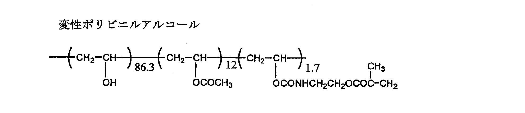
下記の棒状液晶性化合物 1.8g
エチレンオキサイド変性トリメチロールプロパントリアクリレート
(V#360、大阪有機化学(株)製) 0.2g
光重合開始剤(イルガキュアー907、チバガイギー社製) 0.06g
増感剤(カヤキュアーDETX、日本化薬(株)製) 0.02g
メチルエチルケトン 3.9g
―――――――――――――――――――――――――――――――――
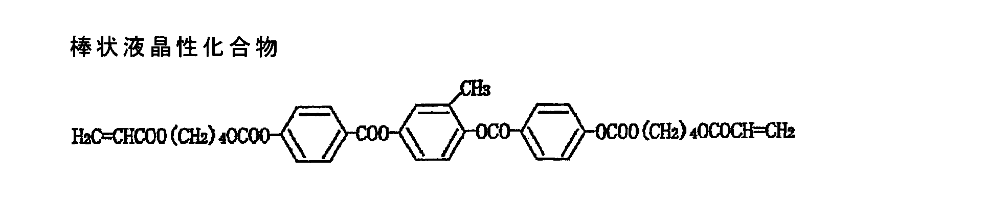
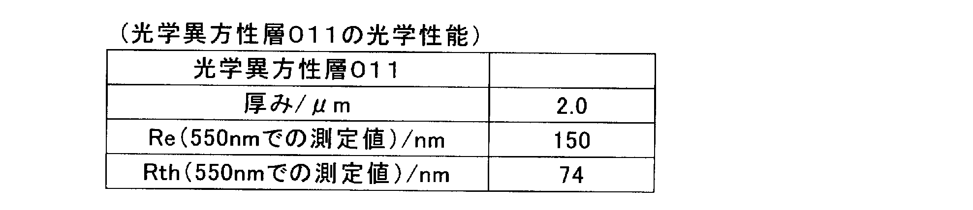

実施例1のセルロースアシレートフィルム001を用い、光学異方性層011を形成する代わりに、下記の光学異方性層012を形成した。
(ポリイミド塗布液の調製)
2,2’-ビス(3,4-ジカルボキシフェニル)ヘキサフルオロプロパン酸二無水物(6FDA)及び2,2’-ビス(トリフルオロメチル)-4,4’-ジアミノビフェニル(PFMB)を用いて、下記式で表される繰り返し単位から構成されるポリイミド(Mw=150,000)を合成した。このポリイミドを、15重量%のMIBK(メチルイソブチルケトン)溶液とし、ポリイミド溶液を調製した。なお、6FDA及びPFMBの合成方法は、特許第3735361号に詳細がある。

上記のポリイミド溶液を、実施例1で作製したセルロースアシレートフィルム001に、バーコーターを用いて厚み調整をして直接塗布した後、これを100℃で10分間乾燥し、更に150℃で20分間乾燥厚さ3.7μmのポリイミドからなる光学異方性層012を形成し、セルロースアシレートフィルム001と一体化した光学フィルム102を得た。ポリイミドによる光学異方性層012の光学特性(表3)は、別途、Re及びRthがゼロとみなせる、ガラス基板の上に上記と同様の操作によって上記の光学異方性層012を作製して測定した。また作製した光学フィルム102の光学特性を表4に示す。以上の光学測定は、自動複屈折計KOBRA-21ADH(王子計測器(株)製)を用いて波長550nmにおいて測定した。


(光学フィルム103の作製)
実施例1で、セルロースアシレートフィルム001を用いる代わりに、富士フイルム社製のタックTD80UL(厚み80μm、波長550nmにおけるRe=4nm、Rth=46nm)を用い、実施例1の光学異方性層011の形成方法と同一の方法で、光学異方性層013を形成し、光学フィルム103を得た。光学異方性層013の光学性能は実施例1の光学異方性層011と同等であることを確認した。
また、光学フィルム103について、自動複屈折計KOBRA-21ADH(王子計測器(株)製)を用いて波長550nmにおいて面内のレターデーションRe及び傾斜角を変えてReを測定することで得られる膜厚方向のレターデーションRthを求めた。結果を表5に示す。
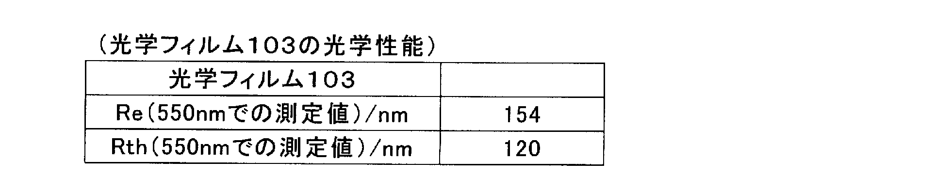
(光学フィルム104の作製)
実施例1で、セルロースアシレートフィルム001を用いる代わりに、富士フィルム社製のZRD60S(厚み60μm、波長550nmにおけるRe=0nm、Rth=1nm)を用い、実施例1の光学異方性層011の形成方法と同一の方法で、光学異方性層014を形成し、光学フィルム104を得た。光学異方性層014の光学性能は実施例1の光学異方性層011と同等であることを確認した。
また、光学フィルム104について、自動複屈折計KOBRA-21ADH(王子計測器(株)製)を用いて波長550nmにおいて面内のレターデーションRe及び傾斜角を変えてReを測定することで得られる膜厚方向のレターデーションRthを求めた。結果を表6に示す。

(セルロースアシレートフィルム002の作製)
実施例1で作製したセルロースアシレートフィルム001と同様にして、厚みを倍にして、波長550nmにおけるRe=-4nm、Rth=-150nmの本発明のセルロースアシレートフィルム002を作製した。Re及びRthについては、自動複屈折計KOBRA-21ADH(王子計測器(株)製)を用いて波長550nmにおいて面内のレターデーションRe及び傾斜角を変えてReを測定することで得られる膜厚方向のレターデーションRthを求めた。
実施例1で、セルロースアシレートフィルム001を用いる代わりに、上記で作製したセルロースアシレートフィルム002を用い、実施例1の光学異方性層011の形成方法と同一の方法で、光学異方性層015を形成し、光学フィルム105を得た。光学異方性層015の光学性能は実施例1の光学異方性層011と同等であることを確認した。また、光学フィルム105について、自動複屈折計KOBRA-21ADH(王子計測器(株)製)を用いて波長550nmにおいて面内のレターデーションRe及び傾斜角を変えてReを測定することで得られる膜厚方向のレターデーションRthを求めた。結果を表7に示す。

実施例1で作製したセルロースアシレートフィルム001を長辺方向に対して45度方向にラビングし、実施例1で使用した配向膜をバーコートで塗布し、100℃、2分乾燥させた。更に実施例1で用いた棒状液晶性化合物をバーコートで塗布し、100℃、2分置いた後、UVを照射し、光学異方性層016を形成し(膜厚2.0μm)、光学フィルム106を作製した。ここで、光学異方性層の波長550nmにおけるReは138nm、Rthは70nm、光学フィルム106の波長550nmにおけるReは137.5nm、Rthは-5nmであり、光学異方性層106の遅相軸は長辺方向に対して45度であった。
特開2009-69793を参考に、100μm周期で波長550nmにおけるReが275nm、Rthは138nmであるパターン1と、Reが0nm、Rthは140nmであるパターン2とが交互になるようにパターニング位相差層をガラス基板上に作製した。これを上記で作製したRe=137.5nmの光学フィルム106上に転写して、パターニング位相差フィルム(光学フィルム107)を作成した。このとき、お互いの軸方向が水平になるようにした。また光学フィルム107全体の波長550nmにおけるRthは134nmであった。
特開2009-223001を参考に、波長550nmにおけるRe=137.5nm、Rth=69nm、遅相軸の向きが100μ周期で45度、-45度となるようにパターニング位相差層をガラス基板上に作製した。これを富士フィルム社製のZRD60S(厚み60μm)上に転写して、パターニング位相差フィルム(光学フィルム108)を作成した。また光学フィルム108全体の波長550nmにおけるRthは76nmであった。
(ハードコート層用塗布液の調製)
下記組成物をミキシングタンクに投入し、攪拌してハードコート層塗布液とした。
メチルエチルケトン900質量部に対して、シクロヘキサノン100質量部、部分カプロラクトン変性の多官能アクリレート(DPCA-20、日本化薬(株)製)750質量部、シリカゾル(MIBK-ST、日産化学工業(株)製)200質量部、光重合開始剤(イルガキュア184、チバ・スペシャルティ・ケミカルズ(株)製)50質量部、を添加して攪拌した。孔径0.4μmのポリプロピレン製フィルターで濾過してハードコート層用の塗布液を調製した。
ZrO2微粒子含有ハードコート剤(デソライトZ7404[屈折率1.72、固形分濃度:60質量%、酸化ジルコニウム微粒子含量:70質量%(対固形分)、酸化ジルコニウム微粒子の平均粒子径:約20nm、溶剤組成:メチルイソブチルケトン/メチルエチルケトン=9/1、JSR(株)製])5.1質量部に、ジペンタエリスリトールペンタアクリレートとジペンタエリスリトールヘキサアクリレートの混合物(DPHA)1.5質量部、光重合開始剤(イルガキュア907、チバ・スペシャルティ・ケミカルズ(株)製)0.05質量部、メチルエチルケトン66.6質量部、メチルイソブチルケトン7.7質量部及びシクロヘキサノン19.1質量部を添加して攪拌した。充分に攪拌の後、孔径0.4μmのポリプロピレン製フィルターで濾過して中屈折率層用塗布液Aを調製した。
ジペンタエリスリトールペンタアクリレートとジペンタエリスリトールヘキサアクリレートの混合物(DPHA)4.5質量部、光重合開始剤(イルガキュア907、チバ・スペシャルティ・ケミカルズ(株)製)0.14質量部、メチルエチルケトン66.5質量部、メチルイソブチルケトン9.5質量部及びシクロヘキサノン19.0質量部を添加して攪拌した。十分に攪拌ののち、孔径0.4μmのポリプロピレン製フィルターで濾過して中屈折率層用塗布液Bを調製した。
ZrO2微粒子含有ハードコート剤(デソライトZ7404[屈折率1.72、固形分濃度:60質量%、酸化ジルコニウム微粒子含量:70質量%(対固形分)、酸化ジルコニウム微粒子の平均粒子径:約20nm、光重合開始剤含有、溶剤組成:メチルイソブチルケトン/メチルエチルケトン=9/1、JSR(株)製])14.4質量部に、ジペンタエリスリトールペンタアクリレートとジペンタエリスリトールヘキサアクリレートの混合物(DPHA)0.75質量部、メチルエチルケトン62.0質量部、メチルイソブチルケトン3.4質量部、シクロヘキサノン1.1質量部を添加して攪拌した。充分に攪拌の後、孔径0.4μmのポリプロピレン製フィルターで濾過して高屈折率層用塗布液Cを調製した。
(パーフルオロオレフィン共重合体(1)の合成)

中空シリカ粒子微粒子ゾル(イソプロピルアルコールシリカゾル、触媒化成工業(株)製CS60-IPA、平均粒子径60nm、シエル厚み10nm、シリカ濃度20質量%、シリカ粒子の屈折率1.31)500質量部に、アクリロイルオキシプロピルトリメトキシシラン30質量部、及びジイソプロポキシアルミニウムエチルアセテート1.51質量部加え混合した後に、イオン交換水9質量部を加えた。60℃で8時間反応させた後に室温まで冷却し、アセチルアセトン1.8質量部を添加し、分散液を得た。その後、シリカの含率がほぼ一定になるようにシクロヘキサノンを添加しながら、圧力30Torrで減圧蒸留による溶媒置換を行い、最後に濃度調整により固形分濃度18.2質量%の分散液Aを得た。得られた分散液AのIPA残存量をガスクロマトグラフィーで分析したところ0.5質量%以下であった。
各成分を下記のように混合し、メチルエチルケトンに溶解して固形分濃度5質量%の低屈折率層用塗布液を作製した。下記各成分の質量%は、塗布液の全固形分に対する、各成分の固形分の比率である。
・DPHA:ジペンタエリスリトールペンタアクリレートとジペンタエリスリトールヘキサアクリレートの混合物(日本化薬(株)製):7質量%
・MF1:国際公開第2003/022906号パンフレットの実施例記載の下記含フッ素不飽和化合物(重量平均分子量1600):5質量%

・分散液A:前記中空シリカ粒子分散液A(アクリロイルオキシプロピルトリメトキシシランで表面修飾した中空シリカ粒子ゾル、固形分濃度18.2%):50質量%
・Irg127:光重合開始剤イルガキュア127(チバ・スペシャルティ・ケミカルズ(株)製):3質量%
更に中屈折率層用塗布液、高屈折率層用塗布液、低屈折率層用塗布液をグラビアコーターを用いて塗布し、中屈折率層、高屈折率層及び低屈折率層を形成した。
中屈折率層の乾燥条件は90℃、30秒とし、紫外線硬化条件は酸素濃度が1.0体積%以下の雰囲気になるように窒素パージしながら180W/cmの空冷メタルハライドランプ(アイグラフィックス(株)製)を用いて、照度300mW/cm2、照射量240mJ/cm2の照射量とした。中屈折率層の膜厚は65.5nm、屈折率1.638はであった。
高屈折率層の乾燥条件は90℃、30秒とし、紫外線硬化条件は酸素濃度が1.0体積%以下の雰囲気になるように窒素パージしながら240W/cmの空冷メタルハライドランプ(アイグラフィックス(株)製)を用いて、照度300mW/cm2、照射量240mJ/cm2の照射量とした。高屈折率層の膜厚は110nm、屈折率は1.845であった。
低屈折率層の乾燥条件は90℃、30秒とし、紫外線硬化条件は酸素濃度が0.1体積%以下の雰囲気になるように窒素パージしながら240W/cmの空冷メタルハライドランプ(アイグラフィックス(株)製)を用いて、照度600mW/cm2、照射量600mJ/cm2の照射量とした。低屈折率層の膜厚は86nm、屈折率は1.42であった。
上記のようにして光学異方性層上にハードコート層及び反射防止層を有する光学フィルム110を作製した。光学フィルム110について、自動複屈折計KOBRA-21ADH(王子計測器(株)製)を用いて波長550nmにおいて面内のレターデーションRe及び傾斜角を変えてReを測定することで得られる膜厚方向のレターデーションRthを求めた。Re=150nm、Rth=-1nmであった。
実施例1で作成した光学フィルム101の支持体であるセルロースアシレートフィルム001上に、前記組成のハードコート層用塗布液をグラビアコーターを用いて塗布した。100℃で乾燥した後、酸素濃度が1.0体積%以下の雰囲気になるように窒素パージしながら160W/cmの空冷メタルハライドランプ(アイグラフィックス(株)製)を用いて、照度400mW/cm2、照射量150mJ/cm2の紫外線を照射して塗布層を硬化させ、厚さ12μmのハードコート層Aを形成した。
更に中屈折率層用塗布液、高屈折率層用塗布液、低屈折率層用塗布液をグラビアコーターを用いて塗布し、中屈折率層、高屈折率層及び低屈折率層を形成し、光学フィルム111を作製した。
中屈折率層の乾燥条件は90℃、30秒とし、紫外線硬化条件は酸素濃度が1.0体積%以下の雰囲気になるように窒素パージしながら180W/cmの空冷メタルハライドランプ(アイグラフィックス(株)製)を用いて、照度300mW/cm2、照射量240mJ/cm2の照射量とした。中屈折率層の膜厚は65.5nm、屈折率1.638はであった。
高屈折率層の乾燥条件は90℃、30秒とし、紫外線硬化条件は酸素濃度が1.0体積%以下の雰囲気になるように窒素パージしながら240W/cmの空冷メタルハライドランプ(アイグラフィックス(株)製)を用いて、照度300mW/cm2、照射量240mJ/cm2の照射量とした。高屈折率層の膜厚は110nm、屈折率は1.845であった。
低屈折率層の乾燥条件は90℃、30秒とし、紫外線硬化条件は酸素濃度が0.1体積%以下の雰囲気になるように窒素パージしながら240W/cmの空冷メタルハライドランプ(アイグラフィックス(株)製)を用いて、照度600mW/cm2、照射量600mJ/cm2の照射量とした。低屈折率層の膜厚は86nm、屈折率は1.42であった。
上記のようにして光学異方性層上にハードコート層及び反射防止層を有する光学フィルム111を作製した。光学フィルム111について、自動複屈折計KOBRA-21ADH(王子計測器(株)製)を用いて波長550nmにおいて面内のレターデーションRe及び傾斜角を変えてReを測定することで得られる膜厚方向のレターデーションRthを求めた。Re=150nm、Rth=-1nmであった。
(光学フィルム112の作製)
富士フイルム社製のZRD60S(厚さ60μm)上に、前記組成のハードコート層用塗布液をグラビアコーターを用いて塗布した。100℃で乾燥した後、酸素濃度が1.0体積%以下の雰囲気になるように窒素パージしながら160W/cmの空冷メタルハライドランプ(アイグラフィックス(株)製)を用いて、照度400mW/cm2、照射量150mJ/cm2の紫外線を照射して塗布層を硬化させ、厚さ12μmのハードコート層Aを形成した。
更に中屈折率層用塗布液、高屈折率層用塗布液、低屈折率層用塗布液をグラビアコーターを用いて塗布し、中屈折率層、高屈折率層及び低屈折率層を形成し、反射防止フィルムを作製した。
中屈折率層の乾燥条件は90℃、30秒とし、紫外線硬化条件は酸素濃度が1.0体積%以下の雰囲気になるように窒素パージしながら180W/cmの空冷メタルハライドランプ(アイグラフィックス(株)製)を用いて、照度300mW/cm2、照射量240mJ/cm2の照射量とした。中屈折率層の膜厚は65.5nm、屈折率1.638はであった。
高屈折率層の乾燥条件は90℃、30秒とし、紫外線硬化条件は酸素濃度が1.0体積%以下の雰囲気になるように窒素パージしながら240W/cmの空冷メタルハライドランプ(アイグラフィックス(株)製)を用いて、照度300mW/cm2、照射量240mJ/cm2の照射量とした。高屈折率層の膜厚は110nm、屈折率は1.845であった。
低屈折率層の乾燥条件は90℃、30秒とし、紫外線硬化条件は酸素濃度が0.1体積%以下の雰囲気になるように窒素パージしながら240W/cmの空冷メタルハライドランプ(アイグラフィックス(株)製)を用いて、照度600mW/cm2、照射量600mJ/cm2の照射量とした。低屈折率層の膜厚は86nm、屈折率は1.42であった
。
以上のように作製した反射防止フィルムに、ポリビニルアルコール系接着剤を用いて、反射防止フィルムの支持体側(ZRD60S)が、実施例1で作製した光学フィルム101の光学異方性層側となるように光学フィルム101に貼り付けた。
以上のようにして光学フィルム112を作製した。光学フィルム112について、自動複屈折計KOBRA-21ADH(王子計測器(株)製)を用いて波長550nmにおいて面内のレターデーションRe及び傾斜角を変えてReを測定することで得られる膜厚方向のレターデーションRthを求めた。Re=150nm、Rth=-1nmであった。
(セルロースアシレートフィルム003の作製)
実施例1で作製したセルロースアシレートフィルム001と同様にして、厚みを1.5倍にして、波長550nmにおけるRe=-3nm、Rth=-112nmの本発明のセルロースアシレートフィルム003を作製した。
実施例1で、セルロースアシレートフィルム001を用いる代わりに、上記で作製したセルロースアシレートフィルム003を用い、実施例1の光学異方性層011の形成方法と同一の方法で、光学異方性層を形成した。光学異方性層の光学性能は実施例1の光学異方性層011と同等であることを確認した。
続いて富士フイルム社製のタックTD80UL(厚み80μm)上に、前記組成のハードコート層用塗布液をグラビアコーターを用いて塗布した。100℃で乾燥した後、酸素濃度が1.0体積%以下の雰囲気になるように窒素パージしながら160W/cmの空冷メタルハライドランプ(アイグラフィックス(株)製)を用いて、照度400mW/cm2、照射量150mJ/cm2の紫外線を照射して塗布層を硬化させ、厚さ12μmのハードコート層Aを形成した。
更に中屈折率層用塗布液、高屈折率層用塗布液、低屈折率層用塗布液をグラビアコーターを用いて塗布し、中屈折率層、高屈折率層及び低屈折率層を形成し、反射防止フィルムを作製した。
中屈折率層の乾燥条件は90℃、30秒とし、紫外線硬化条件は酸素濃度が1.0体積%以下の雰囲気になるように窒素パージしながら180W/cmの空冷メタルハライドランプ(アイグラフィックス(株)製)を用いて、照度300mW/cm2、照射量240mJ/cm2の照射量とした。中屈折率層の膜厚は65.5nm、屈折率1.638はであった。
高屈折率層の乾燥条件は90℃、30秒とし、紫外線硬化条件は酸素濃度が1.0体積%以下の雰囲気になるように窒素パージしながら240W/cmの空冷メタルハライドランプ(アイグラフィックス(株)製)を用いて、照度300mW/cm2、照射量240mJ/cm2の照射量とした。高屈折率層の膜厚は110nm、屈折率は1.845であった。
低屈折率層の乾燥条件は90℃、30秒とし、紫外線硬化条件は酸素濃度が0.1体積%以下の雰囲気になるように窒素パージしながら240W/cmの空冷メタルハライドランプ(アイグラフィックス(株)製)を用いて、照度600mW/cm2、照射量600mJ/cm2の照射量とした。低屈折率層の膜厚は86nm、屈折率は1.42であった。
以上のように作製した反射防止フィルムに、ポリビニルアルコール系接着剤を用いて、反射防止フィルムの支持体側(TD80UL)が、上記光学異方性層側となるように貼り付けた。以上のようにして光学フィルム113を作製した。光学フィルム113について、自動複屈折計KOBRA-21ADH(王子計測器(株)製)を用いて波長550nmにおいて面内のレターデーションRe及び傾斜角を変えてReを測定することで得られる膜厚方向のレターデーションRthを求めた。Re=150nm、Rth=3nmであった。
(セルロースアシレートフィルム004の作製)
実施例1におけるセルロースアシレートフィルム001の作製において、セルロースアシレート溶液中に下記のUV吸収剤Aを1.2質量%添加し、更に下記のRth低減Bを4質量%入れた以外は、実施例1におけるセルロースアシレートフィルム001の作製と同様にしてセルロースアシレートフィルム004を作製した。得られたセルロースアシレートフィルム004のReは-2nm、Rthは-75nmであった。

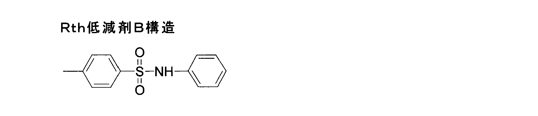
実施例1で、セルロースアシレートフィルム001を用いる代わりに、上記で作製したセルロースアシレートフィルム004を用い、実施例1の光学異方性層011の形成方法と同一の方法で、光学異方性層を形成し、光学フィルム114を得た。ここで、光学異方性層の光学性能は実施例1の光学異方性層011と同等であることを確認した。実施例1と同様の手法で光学フィルム114のRe及びRthを求めた。結果を表8に示す。

(セルロースアシレートフィルム005の作製)
実施例1におけるセルロースアシレートフィルム001の作製において、原料となるセルロースをアセチル置換度2.86のものに変更し、セルロースアシレート溶液中に前記UV吸収剤Aを1.2質量%添加し、更に下記の可塑剤を併せて11質量%入れた以外は、実施例1におけるセルロースアシレートフィルム001の作製と同様にしてセルロースアシレートフィルム005を作製した。得られたセルロースアシレートフィルム005の波長550nmにおけるReは2nm、Rthは48nmであった。
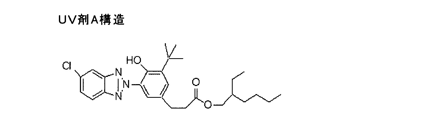
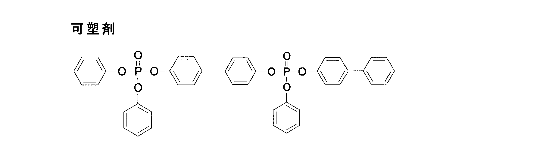
実施例1で、セルロースアシレートフィルム001を用いる代わりに、上記で作製したセルロースアシレートフィルム005を用い、実施例1の光学異方性層011の形成方法と同一の方法で、光学異方性層を形成し、光学フィルム115を得た。ここで、光学異方性層の光学性能は実施例1の光学異方性層011と同等であることを確認した。実施例1と同様の手法で光学フィルム115のRe及びRthを求めた。結果を表9に示す。

(セルロースアシレートフィルム006の作製)
実施例1におけるセルロースアシレートフィルム001の作製において、原料となるセルロースをアセチル置換度2.94のものに変更し、ドープを80℃で30分過熱溶融した。セルロースアシレート溶液中に前記UV吸収剤Aを1.2質量%添加し、前記のRth低減Bを11質量%入れた以外は、実施例1におけるセルロースアシレートフィルム001の作製と同様にしてセルロースアシレートフィルム006を作製した。得られたセルロースアシレートフィルム006の波長550nmにおけるReは-1nm、Rthは-1nmであった。

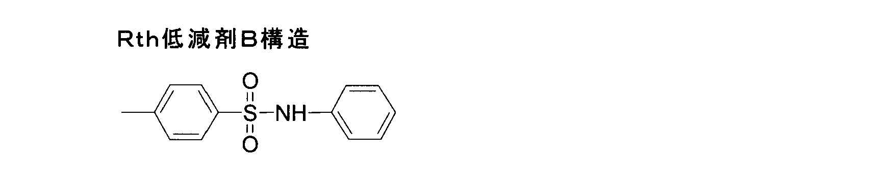
実施例1で、セルロースアシレートフィルム001を用いる代わりに、上記で作製したセルロースアシレートフィルム006を用い、実施例1の光学異方性層011の形成方法と同一の方法で、光学異方性層を形成し、光学フィルム116を得た。ここで、光学異方性層の光学性能は実施例1の光学異方性層011と同等であることを確認した。実施例1と同様の手法で光学フィルム116のRe及びRthを求めた。結果を表10に示す。

(セルロースアシレートフィルム007の作製)
実施例8で作製したセルロースアシレートフィルム004と同様にして、厚みのみを倍にして、波長550nmにおけるRe=-3nm、Rth=-149nmの本発明のセルロースアシレートフィルム007を作製した。
実施例1で、セルロースアシレートフィルム001を用いる代わりに、上記で作製したセルロースアシレートフィルム007を用い、実施例1の光学異方性層011の形成方法と同一の方法で、光学異方性層を形成し、光学フィルム117を得た。ここで、光学異方性層の光学性能は実施例1の光学異方性層011と同等であることを確認した。実施例1と同様の手法で光学フィルム117のRe及びRthを求めた。結果を表11に示す。

(セルロースアセテートフィルム008の作製)
下記の組成物をミキシングタンクに投入し、加熱しながら攪拌して、各成分を溶解し、セルロースアセテート溶液を調製した。
(セルロースアセテート溶液組成)
酢化度60.7~61.1%のセルロースアセテート 100質量部
トリフェニルホスフェート(可塑剤) 7.8質量部
ビフェニルジフェニルホスフェート(可塑剤) 3.9質量部
メチレンクロライド(第1溶媒) 336質量部
メタノール(第2溶媒) 29質量部
1-ブタノール(第3溶媒) 11質量部
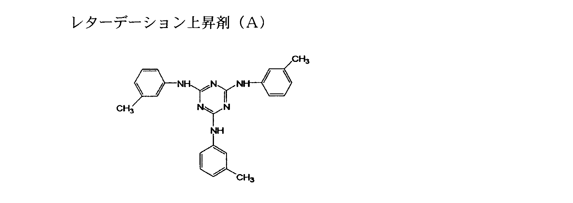
セルロースアシレートフィルムT1を、温度60℃の誘電式加熱ロールを通過させ、フィルム表面温度を40℃に昇温した後に、フィルムの片面に下記に示す組成のアルカリ溶液を、バーコーターを用いて塗布量14ml/m2で塗布し、110℃に加熱した(株)ノリタケカンパニーリミテド製のスチーム式遠赤外ヒーターの下に、10秒間搬送した。続いて、同じくバーコーターを用いて、純水を3ml/m2塗布した。次いで、ファウンテンコーターによる水洗とエアナイフによる水切りを3回繰り返した後に、70℃の乾燥ゾーンに10秒間搬送して乾燥し、アルカリ鹸化処理したセルロースアシレートフィルムを作製した。
──────────────────────────────────
アルカリ溶液組成(質量部)
──────────────────────────────────
水酸化カリウム 4.7質量部
水 15.8質量部
イソプロパノール 63.7質量部
界面活性剤
SF-1:C14H29O(CH2CH2O)20H 1.0質量部
プロピレングリコール 14.8質量部
──────────────────────────────────
上記のように鹸化処理した長尺状のセルロースアセテートフィルムに、下記の組成の配向膜塗布液を#14のワイヤーバーで連続的に塗布した。60℃の温風で60秒、更に100℃の温風で120秒乾燥した。
配向膜塗布液の組成
――――――――――――――――――――――――――――――――――
実施例1で用いた変性ポリビニルアルコール 10質量部
水 371質量部
メタノール 119質量部
グルタルアルデヒド 0.5質量部
光重合開始剤(イルガキュアー2959、チバ・ジャパン製)0.3質量部
――――――――――――――――――――――――――――――――――
上記作製した配向膜に連続的にラビング処理を施した。このとき、長尺状のフィルムの長手方向と搬送方向は平行であり、フィルム長手方向に対して、ラビングローラーの回転軸は時計回りに45°の方向とした。
――――――――――――――――――――――――――――――――――
下記のディスコティック液晶性化合物 91質量部
エチレンオキサイド変性トリメチロールプロパントリアクリレート
(V#360、大阪有機化学(株)製) 9質量部
光重合開始剤(イルガキュアー907、チバガイギー社製) 3質量部
増感剤(カヤキュアーDETX、日本化薬(株)製) 1質量部
下記のピリジニウム塩 0.5質量部
下記のフッ素系ポリマー(FP2) 0.4質量部
メチルエチルケトン 195質量部
―――――――――――――――――――――――――――――――――――
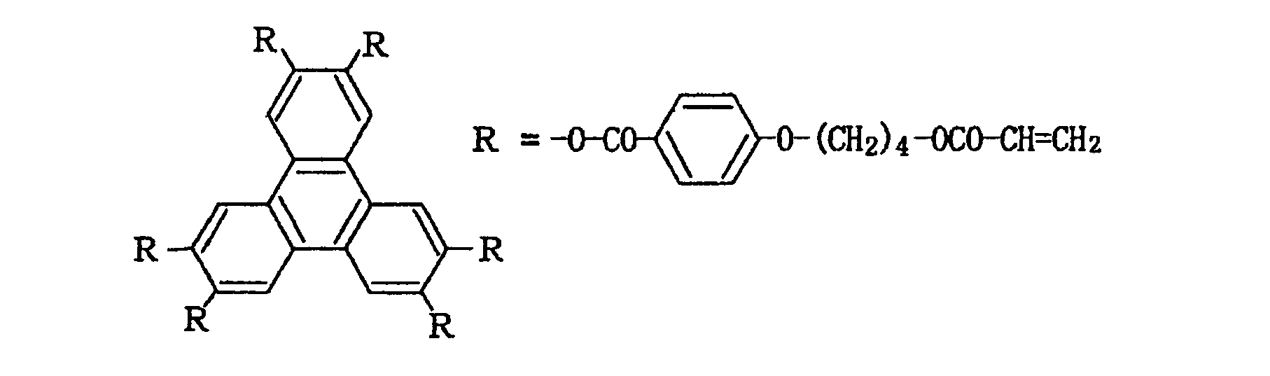



(アクリル樹脂の作成)
特開2008-146003を参考に、メタクリル酸メチル89.2質量部、アクリル酸メチル5.8質量部、及びキシレン5質量部からなる単量体混合物に、1,1-ジ-t-ブチルパ-オキシ-3,3,5-トリメチルシクロヘキサン0.0294質量部、及びn-オクチルメルカプタン0.115質量部を用いたメタクリル酸メチル/アクリル酸メチル共重合体(P-1)のペレット、及び、スチレン75.2質量%、メタクリル酸4.8質量%、エチルベンゼン20質量%を調合液とし、重合開始剤として1,1-tert-ブチルパ-オキシ-3,3,5-トリメチルシクロヘキサンを用いたスチレン/メタクリル酸共重合体(P-2)のペレットを得た。
上記P-1:60質量部、上記P-2:40質量部、旭電化(株)社製、アデカスタブLA-31(UV吸収剤):1質量部と調整した樹脂組成物を用い、特開2008-146003の実施例21を参考に、膜厚40μmのアクリルフィルム009を得た。得られたアクリルフィルム009のRe及びRthは自動複屈折計KOBRA-21ADH(王子計測器(株)製)を用いて波長550nmにおいて測定した。結果を下記表13示す。
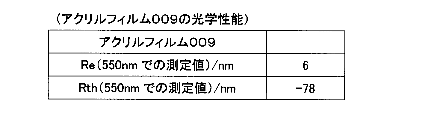
実施例1の光学異方性層011の作製において、配向膜及び光学異方性層011をセルロースアシレートフィルム001上ではなく、ガラス上に作製した。作製した光学異方性層011を剥がし、上記で作成したアクリルフィルム009上に、粘着剤を用いて貼り付け、光学フィルム119とした。この時、アクリルフィルム009の遅相軸と光学異方性層の遅相軸は45°で交差するように配置した。また、光学異方性層の光学性能(Re及びRth)は自動複屈折計KOBRA-21ADH(王子計測器(株)製)を用いて波長550nmにおいて測定したところ、Re=134nm、Rth=75nmであった。
実施例1と同様の手法で光学フィルム119のRe及びRthを求めた。結果を表14に示す。
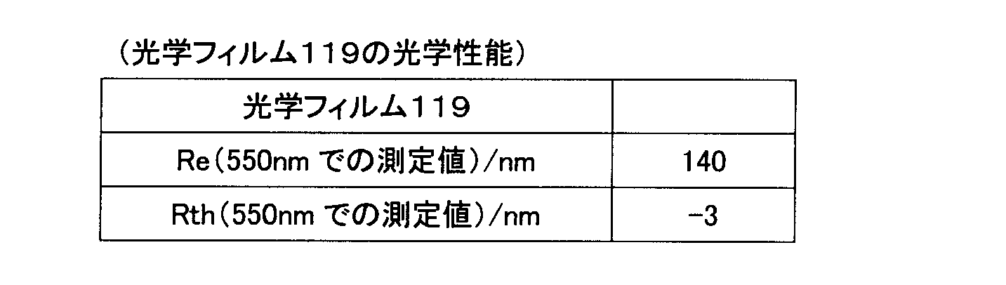
[セルロースフィルム010の作製]
富士フイルム社製のタックTD80UL(厚み80μm)を、180℃条件下で20%延伸し、膜厚68μmのフィルム010を作製した。得られたフィルム010のRe及びRthは自動複屈折計KOBRA-21ADH(王子計測器(株)製)を用いて波長550nmにおいて測定した。結果を下記表15示す。

上記で作成したセルロースフィルム010上に、実施例9の光学異方性層017の作製と同様にして、光学異方性層018を作製し、光学フィルム120を作成した。ここで、光学異方性層018の光学性能は実施例9の光学異方性層017と同等であることを確認した。
実施例1と同様の手法で光学フィルム120のRe及びRthを求めた。結果を表16に示す。

富士フイルム社製のタックTD80UL(厚み80μm)上に、実施例9の光学異方性層017と同様にして光学異方性層を作製し、光学フィルム121を作製した。ここで、光学異方性層の光学性能は実施例9の光学異方性層017と同等であることを確認した。
実施例1と同様の手法で光学フィルム121のRe及びRthを求めた。結果を表17に示す。

実施例1で作製したセルロースアシレートフィルム001上に、実施例9の光学異方性層017と同様にして光学異方性層を作製し、複合支持体Aとした。ここで、光学異方性層の光学性能は実施例9の光学異方性層017と同等であることを確認した。複合支持体Aの波長550nmにおけるReは138nm、Rthは135nmであった。更に、比較例4と同様に、ガラス基板上にパターニング位相差層を形成し、上記光学異方性層上にパターニング位相差層を転写して、パターニング位相差フィルム(光学フィルム122)を作成した。このとき、お互いの軸方向が水平になるようにした。また光学フィルム122全体の波長550nmにおけるRthは2nmであった。
比較例5と同様にガラス基板上にパターニング位相差層を形成し、実施例1のセルロースアシレートフィルム001上に転写して、パターニング位相差フィルム(光学フィルム123)を作成した。また光学フィルム123全体の波長550nmにおけるRthは5nmであった。
上記の実施例1~13及び比較例1~9にて作製したフィルムに、下記の粘着剤塗布液及び上層塗布液Bを、透明支持体側(実施例4~7のフィルム110~113については光学異方性層011上)にそれぞれ20ml/m2塗布し、100℃で5分乾燥して粘着剤付きフィルム試料とした。
下記水溶性ポリマー(m) 0.5g
アセトン 40ml
酢酸エチル 55ml
イソプロパノール 5ml
ポリビニルアルコール(日本合成化学工業株式会社製ゴーセノールNH-26)
0.3g
サポニン(メルク社製界面活性剤) 0.03g
純水 57ml
メタノール 40ml
メチルプロピレングリコール 3ml

[評価1]
液晶シャッター眼鏡方式の3D-TV(SHARP製 LC46LV3)のフロント偏光板をはがし、実施例1~11の偏光板と、比較例1~3及び6~9の偏光板を貼合した。また、液晶シャッター眼鏡に使われているTV側の偏光板を剥がした。次に、左目/右目側の偏光板と液晶層の間に、液晶の遅相軸と遅相軸が垂直になるよう、λ/4板を配置した。
眼鏡を通した位置に分光放射輝度計(SR-3 トプコン製)をおき、それぞれの偏光板が貼り合わされたときの白輝度を、正面及び極角60度方位角45度方向(以下斜め方向)からそれぞれ測定した。斜め方向からの輝度測定時、液晶シャッター眼鏡を画面中央部に向けた。
偏光板貼合前後を比較して、正面では比較例7を除いた全ての偏光板で、白輝度が5%以上向上した。斜め方向においては、比較例1~3及び6~8は白輝度が5%以上低下したが、実施例1~11は同等であった。
(このときの輝度をそれぞれY_RR、Y_RLとしたとき、CRO = (YRR-YRL)/(YRR + YRL)とした。)
クロストークが低いほど、立体感を維持できることを示す。
正面におけるクロストークは、顔を傾けた時のクロストークである。斜め方向におけるクロストークは、斜め方向においた液晶シャッター眼鏡を画面中央部に向けた時のクロストークである。
偏光板貼合前後を比較して、正面では全ての偏光板でクロストークは無くなった。また斜め方向においては、比較例1~3及び6~8のクロストークは10%以上高くなったのに対し、実施例1~11と比較例9は10%以上低くなった。
HPL02065(HP製)のフロント偏光板をはがし、実施例12と13及び比較例4と5の偏光板を貼合した。
同様に、眼鏡を通した位置に分光放射輝度計(SR-3 トプコン製)をおき、それぞれの偏光板が貼り合わされたときの白輝度とクロストークを測定した。
正面及び極角60度方位角45度方向(以下斜め方向)からそれぞれ測定した。斜め方向からの輝度測定時、眼鏡を画面中央部に向けた。
偏光板貼合前後を比較して、正面では全ての偏光板で、白輝度が同等であった。斜め方向においては、比較例4及び5の白輝度は同等だったが、実施例12及び13は5%以上向上した。
偏光板貼合前後を比較して、正面では全ての偏光板でクロストークは同等であった。斜め方向においては、比較例4及び5のクロストークは同等であったのに対し、実施例12及び13では10%以上低下した。
本出願は、2010年2月18日出願の日本特許出願(特願2010-034127)及び2010年9月15日出願の日本特許出願(特願2010-207331)に基づくものであり、その内容はここに参照として取り込まれる。
Claims (8)
- 液晶層と、
該液晶層を挟んで配置され、それぞれ偏光膜と該偏光膜の少なくとも外側の面に設けられた保護膜とを有する、光源側に配置される第一偏光板と、視認側に配置される第二偏光板とを有する液晶表示装置において、
前記第二偏光板の視認側の保護膜は、下記式(I)を満たす透明支持体と、λ/4機能を有する光学異方性層を含み、
前記第二偏光板の視認側の保護膜のRthが|Rth|≦20
である液晶表示装置。
(I) 0≦|Re(550)|≦10
ここで、前記Re(550)は波長550nmにおける正面レターデーション値(単位:nm)、前記Rthは波長550nmにおける膜厚方向のレターデーション値(単位:nm)であり、ある対象物に対して下記式により定義されるものである。
Re=(nx-ny)×d
Rth=((nx+ny)/2-nz)×d
式中、nxは前記対象物面内における遅相軸方向の屈折率を表し、nyは該面内においてnxに直交する方向の屈折率を表し、nzはnx及びnyに直交する方向の屈折率を表す。dは前記nzの方向での前記対象物の膜厚である。 - 前記第二偏光板の視認側の保護膜において、
前記透明支持体のRthと前記光学異方性層のRthの合計が|Rth|≦20
である請求項1に記載の液晶表示装置。 - 液晶層と、
該液晶層を挟んで配置され、それぞれ偏光膜と該偏光膜の少なくとも外側の面に設けられた保護膜とを有する、光源側に配置される第一偏光板と、視認側に配置される第二偏光板とを有する液晶表示装置において、
前記第二偏光板の視認側の保護膜は、下記式(I)を満たす透明支持体と、λ/4機能を有する光学異方性層を含み、
前記透明支持体のRthと前記光学異方性層のRthの合計が|Rth|≦20
である液晶表示装置。
(I) 0≦|Re(550)|≦10
ここで、前記Re(550)は波長550nmにおける正面レターデーション値(単位:nm)、前記Rthは波長550nmにおける膜厚方向のレターデーション値(単位:nm)であり、ある対象物に対して下記式により定義されるものである。
Re=(nx-ny)×d
Rth=((nx+ny)/2-nz)×d
式中、nxは前記対象物面内における遅相軸方向の屈折率を表し、nyは該面内においてnxに直交する方向の屈折率を表し、nzはnx及びnyに直交する方向の屈折率を表す。dは前記nzの方向での前記対象物の膜厚である。 - 前記第二偏光板の視認側保護膜が、更に最表面に1層以上の反射防止フィルムを有する請求項1~3のいずれか1項に記載の液晶表示装置。
- 紫外線吸収剤が、前記第二偏光板の保護膜を構成する透明支持体、光学異方性層、反射防止フィルム、又はそれら同士を接着する接着剤のいずれかに含まれている請求項1~4のいずれか1項に記載の液晶表示装置。
- 前記第二偏光板の保護膜を構成する透明支持体が熱可塑性樹脂を主成分とする請求項1~5のいずれか1項に記載の液晶表示装置。
- 請求項1~6のいずれか1項に記載の液晶表示装置の製造方法であって、前記第二偏光板の保護膜は、共流延法で製造する液晶表示装置の製造方法。
- 視認側に、偏光板を有する画像表示装置であって、
前記偏光板が、偏光膜と少なくともその視認側に保護膜とを有し、
前記偏光板の視認側の保護膜は、下記式(I)を満たす透明支持体と、λ/4機能を有する光学異方性層を含み、
前記偏光板の視認側の保護膜のRthが|Rth|≦20
である画像表示装置。
(I) 0≦|Re(550)|≦10
ここで、前記Re(550)は波長550nmにおける正面レターデーション値(単位:nm)、前記Rthは波長550nmにおける膜厚方向のレターデーション値(単位:nm)であり、ある対象物に対して下記式により定義されるものである。
Re=(nx-ny)×d
Rth=((nx+ny)/2-nz)×d
式中、nxは前記対象物面内における遅相軸方向の屈折率を表し、nyは該面内においてnxに直交する方向の屈折率を表し、nzはnx及びnyに直交する方向の屈折率を表す。dは前記nzの方向での前記対象物の膜厚である。
Priority Applications (4)
| Application Number | Priority Date | Filing Date | Title |
|---|---|---|---|
| KR1020127004820A KR101296179B1 (ko) | 2010-02-18 | 2011-02-18 | 액정표시장치 및 그 제조방법, 그리고 화상표시장치 |
| CN201180019663.2A CN102870039B (zh) | 2010-02-18 | 2011-02-18 | 液晶显示装置、其制备方法以及图像显示装置 |
| BR112012020734A BR112012020734A2 (pt) | 2010-02-18 | 2011-02-18 | dispositivo de exibição de cristal líquido, método para fabricação do mesmo, e dispositivo de exibição de imagem. |
| US13/391,785 US8305525B2 (en) | 2010-02-18 | 2011-02-18 | Liquid crystal display device, method for manufacturing the same, and image display device |
Applications Claiming Priority (4)
| Application Number | Priority Date | Filing Date | Title |
|---|---|---|---|
| JP2010-034127 | 2010-02-18 | ||
| JP2010034127 | 2010-02-18 | ||
| JP2010-207331 | 2010-09-15 | ||
| JP2010207331 | 2010-09-15 |
Publications (1)
| Publication Number | Publication Date |
|---|---|
| WO2011102493A1 true WO2011102493A1 (ja) | 2011-08-25 |
Family
ID=44483078
Family Applications (1)
| Application Number | Title | Priority Date | Filing Date |
|---|---|---|---|
| PCT/JP2011/053579 Ceased WO2011102493A1 (ja) | 2010-02-18 | 2011-02-18 | 液晶表示装置及びその製造方法、並びに画像表示装置 |
Country Status (6)
| Country | Link |
|---|---|
| US (1) | US8305525B2 (ja) |
| JP (1) | JP4825934B1 (ja) |
| KR (1) | KR101296179B1 (ja) |
| CN (1) | CN102870039B (ja) |
| BR (1) | BR112012020734A2 (ja) |
| WO (1) | WO2011102493A1 (ja) |
Cited By (1)
| Publication number | Priority date | Publication date | Assignee | Title |
|---|---|---|---|---|
| WO2012050019A1 (ja) * | 2010-10-13 | 2012-04-19 | コニカミノルタオプト株式会社 | 前面板付き液晶表示装置の製造方法、前面板付き液晶表示装置 |
Families Citing this family (8)
| Publication number | Priority date | Publication date | Assignee | Title |
|---|---|---|---|---|
| WO2014042022A1 (ja) * | 2012-09-13 | 2014-03-20 | 富士フイルム株式会社 | 画像表示装置 |
| US9891360B2 (en) | 2012-11-29 | 2018-02-13 | Lg Chem, Ltd. | Optical film |
| WO2016129645A1 (ja) | 2015-02-10 | 2016-08-18 | 富士フイルム株式会社 | 光学部材、光学素子、液晶表示装置および近接眼光学部材 |
| WO2017057526A1 (ja) * | 2015-09-30 | 2017-04-06 | 富士フイルム株式会社 | ハードコートフィルム、偏光板及び画像表示装置 |
| US10162213B2 (en) * | 2015-10-20 | 2018-12-25 | Korea Advanced Institute Institute Of Science And Technology | Method of producing polarizing light-emitting film using photoluminescent ferroelectric liquid crystal molecules and liquid crystal display comprising the same |
| JP7258497B2 (ja) * | 2017-09-29 | 2023-04-17 | 日東電工株式会社 | 透明粘着フィルム |
| JP7357008B2 (ja) | 2019-01-17 | 2023-10-05 | 富士フイルム株式会社 | 積層体および画像表示装置 |
| KR20240141999A (ko) * | 2023-03-21 | 2024-09-30 | 삼성에스디아이 주식회사 | 편광판 및 광학표시장치 |
Citations (4)
| Publication number | Priority date | Publication date | Assignee | Title |
|---|---|---|---|---|
| JP2002328233A (ja) * | 2001-05-02 | 2002-11-15 | Kanegafuchi Chem Ind Co Ltd | 透明フィルム |
| WO2007119560A1 (ja) * | 2006-03-31 | 2007-10-25 | Zeon Corporation | 偏光板, 液晶表示装置, および, 保護フィルム |
| JP2008170557A (ja) * | 2007-01-09 | 2008-07-24 | Arisawa Mfg Co Ltd | 偏光眼鏡および立体画像表示システム |
| JP2008224763A (ja) * | 2007-03-08 | 2008-09-25 | Fujifilm Corp | 透明保護フィルム、光学補償フィルム、偏光板、及び液晶表示装置 |
Family Cites Families (9)
| Publication number | Priority date | Publication date | Assignee | Title |
|---|---|---|---|---|
| JP3315048B2 (ja) | 1996-01-23 | 2002-08-19 | シャープ株式会社 | 立体画像表示装置 |
| JP3718908B2 (ja) | 1996-07-02 | 2005-11-24 | ソニー株式会社 | 映像投影システム及び偏光眼鏡 |
| JP3767962B2 (ja) * | 1997-02-19 | 2006-04-19 | シャープ株式会社 | 映像表示システム |
| JP3763401B2 (ja) * | 2000-05-31 | 2006-04-05 | シャープ株式会社 | 液晶表示装置 |
| JP4187616B2 (ja) * | 2002-09-06 | 2008-11-26 | 大日本印刷株式会社 | 積層位相差光学素子、その製造方法及び液晶表示装置 |
| JP4027898B2 (ja) | 2004-01-29 | 2007-12-26 | 株式会社有沢製作所 | 偏光透過スクリーン、及び当該偏光透過スクリーンを用いた立体画像表示装置 |
| JP4350052B2 (ja) * | 2004-04-16 | 2009-10-21 | シャープ株式会社 | 円偏光板及び液晶表示装置 |
| KR100677637B1 (ko) * | 2006-02-22 | 2007-02-02 | 삼성전자주식회사 | 고해상도 오토스테레오스코픽 디스플레이 |
| US20080304151A1 (en) | 2007-06-08 | 2008-12-11 | Arisawa Mfg. Co., Ltd. | Stereoscopic image display |
-
2011
- 2011-02-18 JP JP2011034024A patent/JP4825934B1/ja active Active
- 2011-02-18 CN CN201180019663.2A patent/CN102870039B/zh active Active
- 2011-02-18 BR BR112012020734A patent/BR112012020734A2/pt not_active IP Right Cessation
- 2011-02-18 KR KR1020127004820A patent/KR101296179B1/ko active Active
- 2011-02-18 US US13/391,785 patent/US8305525B2/en active Active
- 2011-02-18 WO PCT/JP2011/053579 patent/WO2011102493A1/ja not_active Ceased
Patent Citations (4)
| Publication number | Priority date | Publication date | Assignee | Title |
|---|---|---|---|---|
| JP2002328233A (ja) * | 2001-05-02 | 2002-11-15 | Kanegafuchi Chem Ind Co Ltd | 透明フィルム |
| WO2007119560A1 (ja) * | 2006-03-31 | 2007-10-25 | Zeon Corporation | 偏光板, 液晶表示装置, および, 保護フィルム |
| JP2008170557A (ja) * | 2007-01-09 | 2008-07-24 | Arisawa Mfg Co Ltd | 偏光眼鏡および立体画像表示システム |
| JP2008224763A (ja) * | 2007-03-08 | 2008-09-25 | Fujifilm Corp | 透明保護フィルム、光学補償フィルム、偏光板、及び液晶表示装置 |
Cited By (3)
| Publication number | Priority date | Publication date | Assignee | Title |
|---|---|---|---|---|
| WO2012050019A1 (ja) * | 2010-10-13 | 2012-04-19 | コニカミノルタオプト株式会社 | 前面板付き液晶表示装置の製造方法、前面板付き液晶表示装置 |
| US8947621B2 (en) | 2010-10-13 | 2015-02-03 | Konica Minolta Advanced Layers, Inc. | Liquid crystal display device comprising a front plate having a lamda/4 plate that includes a hard coat layer and method for manufacturing the same |
| JP5678964B2 (ja) * | 2010-10-13 | 2015-03-04 | コニカミノルタ株式会社 | 前面板付き液晶表示装置の製造方法、前面板付き液晶表示装置 |
Also Published As
| Publication number | Publication date |
|---|---|
| US20120147304A1 (en) | 2012-06-14 |
| BR112012020734A2 (pt) | 2016-04-26 |
| CN102870039B (zh) | 2016-01-20 |
| JP4825934B1 (ja) | 2011-11-30 |
| CN102870039A (zh) | 2013-01-09 |
| KR101296179B1 (ko) | 2013-08-14 |
| US8305525B2 (en) | 2012-11-06 |
| JP2012083694A (ja) | 2012-04-26 |
| KR20120028404A (ko) | 2012-03-22 |
Similar Documents
| Publication | Publication Date | Title |
|---|---|---|
| JP5544269B2 (ja) | 光学フィルム、偏光板及び液晶表示装置 | |
| JP4825934B1 (ja) | 液晶表示装置及びその製造方法、並びに画像表示装置 | |
| JP4963732B2 (ja) | 光学フィルム、その製造方法、並びにそれを用いた偏光板、画像表示装置及び立体画像表示システム | |
| JP5038745B2 (ja) | 透明保護フィルム、光学補償フィルム、偏光板、及び液晶表示装置 | |
| JP5481306B2 (ja) | 積層体、光学フィルムおよびそれらの製造方法、偏光板、画像晶表示装置、立体画像表示システム | |
| JP5380029B2 (ja) | 液晶表示装置 | |
| JP2006106715A (ja) | 反射防止フィルム、偏光板、および液晶表示装置 | |
| JP5871615B2 (ja) | 立体表示装置 | |
| US7927672B2 (en) | Optical cellulose acylate film, polarizing plate and liquid crystal display | |
| JP2008255340A (ja) | セルロースアシレートフィルム、偏光板及びそれを用いた液晶表示装置 | |
| JP2006106714A (ja) | 反射防止フィルム、偏光板、および液晶表示装置 | |
| JP4774303B2 (ja) | セルロースアシレートフィルム、光学補償シート、偏光板、及び液晶表示装置 | |
| KR20070052243A (ko) | 편광판 및 액정 표시 장치 | |
| JP5559670B2 (ja) | 時分割2眼立体視の透過型液晶表示装置 | |
| KR20060048050A (ko) | 광학 보상 시트, 편광판, 및 액정 표시 장치 | |
| JP2005134863A (ja) | 光学補償シート、偏光板および液晶表示装置 | |
| JP2007272100A (ja) | 光学フィルム、これを用いた偏光板および液晶表示装置 | |
| JP2005187770A (ja) | 反射防止フィルム、偏光板、および液晶表示装置 | |
| JP5857091B2 (ja) | 立体画像表示装置 | |
| JP2005301246A (ja) | 反射防止フィルム、偏光板、および液晶表示装置 | |
| JP5871480B2 (ja) | 画像表示装置及び3d画像表示システム | |
| JP2010039087A (ja) | 液晶表示装置 | |
| JP4575734B2 (ja) | 光学補償シートおよび偏光板 | |
| JP2005352138A (ja) | セルロースアシレートフィルム、偏光板及び液晶表示装置 |
Legal Events
| Date | Code | Title | Description |
|---|---|---|---|
| WWE | Wipo information: entry into national phase |
Ref document number: 201180019663.2 Country of ref document: CN |
|
| 121 | Ep: the epo has been informed by wipo that ep was designated in this application |
Ref document number: 11744779 Country of ref document: EP Kind code of ref document: A1 |
|
| WWE | Wipo information: entry into national phase |
Ref document number: 13391785 Country of ref document: US |
|
| ENP | Entry into the national phase |
Ref document number: 20127004820 Country of ref document: KR Kind code of ref document: A |
|
| WWE | Wipo information: entry into national phase |
Ref document number: 7177/CHENP/2012 Country of ref document: IN |
|
| NENP | Non-entry into the national phase |
Ref country code: DE |
|
| 122 | Ep: pct application non-entry in european phase |
Ref document number: 11744779 Country of ref document: EP Kind code of ref document: A1 |
|
| REG | Reference to national code |
Ref country code: BR Ref legal event code: B01A Ref document number: 112012020734 Country of ref document: BR |
|
| ENP | Entry into the national phase |
Ref document number: 112012020734 Country of ref document: BR Kind code of ref document: A2 Effective date: 20120817 |