WO2011102209A1 - 作業車両及び作業車両の制御方法 - Google Patents
作業車両及び作業車両の制御方法 Download PDFInfo
- Publication number
- WO2011102209A1 WO2011102209A1 PCT/JP2011/051882 JP2011051882W WO2011102209A1 WO 2011102209 A1 WO2011102209 A1 WO 2011102209A1 JP 2011051882 W JP2011051882 W JP 2011051882W WO 2011102209 A1 WO2011102209 A1 WO 2011102209A1
- Authority
- WO
- WIPO (PCT)
- Prior art keywords
- work
- clutch
- speed
- lock
- connected state
- Prior art date
Links
Images


Classifications
-
- F—MECHANICAL ENGINEERING; LIGHTING; HEATING; WEAPONS; BLASTING
- F16—ENGINEERING ELEMENTS AND UNITS; GENERAL MEASURES FOR PRODUCING AND MAINTAINING EFFECTIVE FUNCTIONING OF MACHINES OR INSTALLATIONS; THERMAL INSULATION IN GENERAL
- F16H—GEARING
- F16H61/00—Control functions within control units of change-speed- or reversing-gearings for conveying rotary motion ; Control of exclusively fluid gearing, friction gearing, gearings with endless flexible members or other particular types of gearing
- F16H61/14—Control of torque converter lock-up clutches
- F16H61/143—Control of torque converter lock-up clutches using electric control means
-
- E—FIXED CONSTRUCTIONS
- E02—HYDRAULIC ENGINEERING; FOUNDATIONS; SOIL SHIFTING
- E02F—DREDGING; SOIL-SHIFTING
- E02F9/00—Component parts of dredgers or soil-shifting machines, not restricted to one of the kinds covered by groups E02F3/00 - E02F7/00
- E02F9/20—Drives; Control devices
- E02F9/202—Mechanical transmission, e.g. clutches, gears
-
- E—FIXED CONSTRUCTIONS
- E02—HYDRAULIC ENGINEERING; FOUNDATIONS; SOIL SHIFTING
- E02F—DREDGING; SOIL-SHIFTING
- E02F9/00—Component parts of dredgers or soil-shifting machines, not restricted to one of the kinds covered by groups E02F3/00 - E02F7/00
- E02F9/20—Drives; Control devices
- E02F9/2058—Electric or electro-mechanical or mechanical control devices of vehicle sub-units
- E02F9/2079—Control of mechanical transmission
-
- B—PERFORMING OPERATIONS; TRANSPORTING
- B60—VEHICLES IN GENERAL
- B60Y—INDEXING SCHEME RELATING TO ASPECTS CROSS-CUTTING VEHICLE TECHNOLOGY
- B60Y2200/00—Type of vehicle
- B60Y2200/40—Special vehicles
- B60Y2200/41—Construction vehicles, e.g. graders, excavators
Definitions
- the present invention relates to a work vehicle and a work vehicle control method.
- the traveling device and the hydraulic pump are driven by the driving force from the engine.
- the vehicle travels by driving the travel device.
- hydraulic oil is supplied from the hydraulic pump to the work machine. Thereby, the work machine is driven.
- Some work vehicles include a torque converter device having a torque converter and a lock-up clutch.
- the torque converter device transmits the driving force from the engine to the traveling device via the torque converter (hereinafter, this state is referred to as “torque converter traveling”).
- torque converter traveling When the lock-up clutch is in the connected state, the torque converter device transmits the driving force from the engine to the travel device via the lock-up clutch (hereinafter, this state is referred to as “lock-up travel”).
- switching between the connected state and the non-connected state of the lockup clutch is automatically performed by the control unit.
- the control unit switches the lockup clutch between the non-connected state and the connected state according to the traveling state of the vehicle. For example, when the vehicle speed reaches a predetermined switching speed, the control unit switches the lockup clutch from the non-connected state to the connected state (see Patent Document 1).
- a work machine may be driven while traveling rather than only traveling.
- the lockup clutch is in a connected state, the engine rotational speed decreases, and the amount of hydraulic oil discharged from the hydraulic pump also decreases. In this case, operation
- the operator disables the lock-up clutch switching control by the control unit by operating a switch or the like. Therefore, the fact is that the lock-up running is not effectively used during the above-described work even though the lock-up running is more effective in reducing the fuel consumption than the torque converter running.
- An object of the present invention is to suppress a decrease in workability and improve fuel efficiency in a work vehicle.
- the work vehicle includes an engine, a traveling device, a hydraulic pump, a work implement, a torque converter device, and a control unit.
- the traveling device is driven by the driving force from the engine to cause the vehicle to travel.
- the hydraulic pump is driven by a driving force from the engine and discharges hydraulic oil.
- the work machine is driven by hydraulic oil from a hydraulic pump.
- the torque converter device includes a torque converter and a lock-up clutch, and transmits driving force from the engine to the traveling device.
- the control unit switches the lockup clutch between a connected state and a non-connected state according to the traveling state of the vehicle.
- the control unit determines whether or not a load increase condition that leads to an increase in load on the work implement is satisfied. When the load increase condition is satisfied, the control unit controls the lockup clutch so that the lockup clutch is in the disconnected state.
- the lock-up clutch is controlled so that the lock-up clutch is in a disconnected state in a work phase where a heavy load is applied to the work machine. Therefore, the work vehicle can perform work by the work machine in a state where the lock-up clutch is in the non-connected state. Thereby, compared with the case where work is performed in a state where the lock-up clutch is in the connected state, it is possible to suppress a decrease in workability by the work implement. Further, in a work phase where a heavy load is not applied to the work implement, fuel consumption can be improved by utilizing lock-up running.
- the work vehicle according to the second aspect of the present invention is the work vehicle according to the first aspect, and the control unit is configured to satisfy the load increase condition when the lockup clutch is in the disconnected state.
- the lock-up clutch is prohibited from being switched to the connected state, and the lock-up clutch is maintained in the non-connected state.
- the work vehicle according to a third aspect of the present invention is the work vehicle according to the first aspect, wherein the control unit locks when the load increasing condition is satisfied when the lock-up clutch is in the connected state.
- the up clutch is switched from the connected state to the disconnected state.
- the lock-up clutch is switched from the connected state to the non-connected state in a work phase where a heavy load is applied to the work machine. Therefore, even if the lockup clutch is in a connected state in a work phase where a heavy load is not applied to the work machine, when the work machine changes to a work phase in which a large load is applied to the work machine, the work vehicle Work with a work machine can be performed in a certain state. Thereby, it can suppress that the workability
- a work vehicle is the work vehicle according to the first aspect, and includes a work machine operating member for operating the work machine and a work machine for detecting an operation amount of the work machine operating member. And an operation detection unit.
- the load increase condition includes that the operation amount of the work implement operation member is larger than a predetermined operation amount threshold.
- the operation amount of the work implement operation member being larger than the predetermined operation amount threshold indicates that the work vehicle is expected to increase the load on the work implement. For this reason, switching to the connection state of a lockup clutch can be prohibited before the load to a working machine increases. Alternatively, the lockup clutch can be switched from the connected state to the disconnected state before the load on the work machine increases. Thereby, when the load to the work machine is increased, it is possible to suppress a decrease in workability of the work machine.
- a work vehicle is the work vehicle according to the fourth aspect, wherein the work machine includes a boom that swings up and down in accordance with an operation of the work machine operation member, and a tip of the boom. And a work attachment to be attached.
- the lockup clutch can be controlled by accurately predicting in advance that the load on the work implement increases. Thereby, when the load to the work machine is increased, it is possible to suppress a decrease in workability of the work machine.
- the work vehicle according to the sixth aspect of the present invention is the work vehicle according to the first aspect, and the load increasing condition includes that the work phase of the work vehicle is excavation.
- the work phase of the work vehicle being excavated indicates that the work vehicle is in a state where the load on the work machine is expected to increase. For this reason, it is possible to control the lockup clutch by accurately predicting in advance that the load on the work machine increases. Thereby, when the load to the work machine is increased, it is possible to suppress a decrease in workability of the work machine.
- a work vehicle according to a seventh aspect of the present invention is the work vehicle according to the fourth aspect, and the traveling device has a transmission capable of shifting from a first speed to a third speed or higher speed stage.
- the load increase condition further includes that the speed stage of the transmission is the second speed.
- the speed stage of the transmission is the second speed.
- the speed stage of the transmission is often the second speed. For this reason, it can suppress that the workability
- a work vehicle is the work vehicle according to the fourth aspect, and further includes a vehicle speed detection unit that detects a vehicle speed.
- the load increase condition further includes that the vehicle speed is equal to or lower than a predetermined speed threshold value.
- Whether or not the work vehicle is expected to increase the load on the work implement can also be determined by the vehicle speed. This is because when the vehicle speed is greater than a predetermined speed threshold, that is, when the vehicle is traveling at a high speed, the driving of the traveling device is more important than the working machine. Conversely, when the vehicle is traveling at a low speed, the driving of the work machine is more important than the traveling device. Therefore, in this work vehicle, it is possible to suppress a decrease in workability by the work machine.
- a work vehicle is the work vehicle according to the second aspect, wherein the control unit is configured to release the lock-up clutch when a predetermined time has elapsed since the load increase condition is not satisfied. Release the prohibition of switching to the connected state.
- a work vehicle control method is a work vehicle control method including an engine, a traveling device, a hydraulic pump, a work implement, a torque converter device, and a control unit.
- This control method includes the following steps. Switching the lockup clutch between a connected state and a non-connected state according to the running state of the vehicle; A step of determining whether or not a load increase condition that leads to an increase in load on the work machine is satisfied. Controlling the lock-up clutch so that the lock-up clutch is disengaged when the load increase condition is satisfied.
- the lock-up clutch is controlled so that the lock-up clutch is in a disconnected state in a work phase where a heavy load is applied to the work machine.
- the present invention in the work vehicle, it is possible to suppress a decrease in workability and improve fuel efficiency.
- FIG. 1 is a side view of a work vehicle according to an embodiment of the present invention.
- the schematic diagram which shows the structure of a working vehicle. The figure which shows the example of an engine torque curve.
- the flowchart which shows the process in lockup prohibition control.
- the flowchart which shows the process in lockup prohibition control.
- the flowchart which shows the process in lockup prohibition control.
- the timing chart which shows operation
- FIG. 1 and FIG. 2 show a work vehicle 1 according to an embodiment of the present invention.
- FIG. 1 is an external view of the work vehicle 1
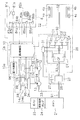
- FIG. 2 is a schematic diagram illustrating the configuration of the work vehicle 1.
- the work vehicle 1 is a wheel loader, and the work vehicle 1 can be self-propelled when the front wheels 4 a and the rear wheels 4 b are rotationally driven, and can perform a desired work using the work machine 3.
- the work vehicle 1 includes a body frame 2, a work implement 3, a front wheel 4a, a rear wheel 4b, and a cab 5.
- the body frame 2 has a front body part 2a and a rear body part 2b.
- the front vehicle body portion 2a and the rear vehicle body portion 2b are connected to each other so as to be swingable in the left-right direction.
- a pair of steering cylinders 11a and 11b are provided across the front vehicle body portion 2a and the rear vehicle body portion 2b.
- the steering cylinders 11a and 11b are hydraulic cylinders that are driven by hydraulic oil from the steering pump 12 (see FIG. 2). As the steering cylinders 11a and 11b expand and contract, the front vehicle body portion 2a swings with respect to the rear vehicle body portion 2b. Thereby, the traveling direction of the vehicle is changed. In FIGS. 1 and 2, only one of the steering cylinders 11a and 11b is shown, and the other is omitted.
- a work machine 3 and a pair of front wheels 4a are attached to the front vehicle body 2a.
- the work machine 3 is driven by hydraulic oil from the work machine pump 13 (see FIG. 2).
- the work machine 3 includes a boom 6, a pair of lift cylinders 14 a and 14 b, a bucket 7, and a bucket cylinder 15.
- the boom 6 is attached to the front vehicle body 2a.
- One ends of the lift cylinders 14a and 14b are attached to the front vehicle body 2a.
- the other ends of the lift cylinders 14 a and 14 b are attached to the boom 6.
- the bucket 7 is attached to the tip of the boom 6.
- One end of the bucket cylinder 15 is attached to the front vehicle body 2a.
- the other end of the bucket cylinder 15 is attached to the bucket 7 via a bell crank 9.
- the bucket cylinder 15 expands and contracts with hydraulic oil from the work implement pump 13, the bucket 7 swings up and down in accordance with the operation of the bucket operation member 84a.
- the cab 5 and a pair of rear wheels 4b are attached to the rear vehicle body 2b.
- the cab 5 is mounted on the upper part of the vehicle body frame 2 and includes a seat on which an operator is seated, an operation unit 8 to be described later, and the like.
- the work vehicle 1 includes an engine 21, a torque converter device 23, a travel device 22, a work machine pump 13, a steering pump 12, an operation unit 8, a control unit 10, and the like.
- the engine 21 is a diesel engine, and the output of the engine 21 is controlled by adjusting the amount of fuel injected into the cylinder. This adjustment is performed by controlling the electronic governor 25 attached to the fuel injection pump 24 of the engine 21 by the first control unit 10a described later.
- the governor 25 an all-speed control type governor is generally used, and the engine speed and the fuel injection amount according to the load so that the engine speed becomes a target speed corresponding to the accelerator operation amount described later. And adjust. That is, the governor 25 increases or decreases the fuel injection amount so that there is no deviation between the target engine speed and the actual engine speed.
- the engine speed is detected by an engine speed sensor 91.
- the detection signal of the engine speed sensor 91 is input to the first control unit 10a.
- the torque converter device 23 has a lockup clutch 27 and a torque converter 28.
- the lockup clutch 27 can be switched between a connected state and a non-connected state.
- the torque converter 28 transmits the driving force from the engine 21 to the traveling device 22 using oil as a medium (hereinafter, this state is referred to as “torque traveling”).
- torque traveling When the lockup clutch 27 is in the connected state, the input side and the output side of the torque converter 28 are directly connected.
- the driving force from the engine 21 is transmitted to the traveling device 22 via the lockup clutch 27 (hereinafter, this state is referred to as “lockup traveling”).
- the lock-up clutch 27 is a hydraulically operated clutch, and the supply of hydraulic oil to the lock-up clutch 27 is controlled by the second control unit 10b described later via the clutch control valve 31, so that the connected state is not connected.
- the connected state is switched.
- the traveling device 22 is a device that causes the vehicle to travel by the driving force from the engine 21.
- the traveling device 22 includes a transmission 26, the front wheels 4a and the rear wheels 4b described above, and the like.
- the transmission 26 has a forward clutch CF corresponding to the forward travel stage and a reverse clutch CR corresponding to the reverse travel stage.
- a forward clutch CF corresponding to the forward travel stage
- a reverse clutch CR corresponding to the reverse travel stage.
- the transmission 26 has a plurality of speed stage clutches C1-C4 corresponding to a plurality of speed stages, and can switch the reduction ratio to a plurality of stages.
- four speed stage clutches C1-C4 are provided, and the speed stage can be switched to four stages from the first speed to the fourth speed.
- Each of the speed stage clutches C1-C4 is a hydraulically operated hydraulic clutch. Hydraulic fluid is supplied from a hydraulic pump (not shown) to the clutches C1-C4 via the clutch control valve 31.
- the clutch control valve 31 is controlled by the second control unit 10b to control the supply of hydraulic oil to the clutch C1-C4, thereby switching the connected state and the non-connected state of each clutch C1-C4.
- the output shaft of the transmission 26 is provided with a T / M output rotational speed sensor 92 that detects the rotational speed of the output shaft of the transmission 26.
- a detection signal from the T / M output rotation speed sensor 92 is input to the second control unit 10b.
- the second control unit 10b calculates the vehicle speed based on the detection signal of the T / M output rotation speed sensor 92. Therefore, the T / M output rotation speed sensor 92 functions as a vehicle speed detection unit that detects the vehicle speed.
- a sensor that detects the rotational speed of other parts instead of the output shaft of the transmission 26 may be used as the vehicle speed detection unit.
- the driving force output from the transmission 26 is transmitted to the front wheels 4a and the rear wheels 4b via the shaft 32 and the like. Thereby, the vehicle travels.
- the rotational speed of the input shaft of the transmission 26 is detected by a T / M input rotational speed sensor 93.
- a detection signal from the T / M input rotation speed sensor 93 is input to the second control
- a part of the driving force of the engine 21 is transmitted to the work machine pump 13 and the steering pump 12 via the PTO shaft 33.
- the work machine pump 13 and the steering pump 12 are hydraulic pumps that are driven by a driving force from the engine 21.
- the hydraulic oil discharged from the work machine pump 13 is supplied to the lift cylinders 14 a and 14 b and the bucket cylinder 15 via the work machine control valve 34.
- the hydraulic oil discharged from the steering pump 12 is supplied to the steering cylinders 11 a and 11 b via the steering control valve 35.
- the work machine 3 is driven by a part of the driving force from the engine 21.
- the pressure of the hydraulic oil discharged from the work machine pump 13 (hereinafter referred to as “work machine pump hydraulic pressure”) is detected by the first hydraulic sensor 94.
- the pressure of the hydraulic oil supplied to the lift cylinders 14 a and 14 b (hereinafter referred to as “lift cylinder hydraulic pressure”) is detected by the second hydraulic pressure sensor 95.
- the second hydraulic pressure sensor 95 detects the hydraulic pressure in the cylinder head chamber to which hydraulic oil is supplied when the lift cylinders 14a and 14b are extended.
- the pressure of hydraulic oil supplied to the bucket cylinder 15 (hereinafter referred to as “bucket cylinder hydraulic pressure”) is detected by a third hydraulic pressure sensor 96.
- the third hydraulic pressure sensor 96 detects the hydraulic pressure in the cylinder head chamber to which hydraulic oil is supplied when the bucket cylinder 15 is extended.
- the pressure of hydraulic fluid discharged from the steering pump 12 (hereinafter referred to as “steering pump hydraulic pressure”) is detected by a fourth hydraulic pressure sensor 97. Detection signals from the first to fourth hydraulic sensors 94-97 are input to the second controller 10b.
- the operation unit 8 is operated by an operator.
- the operation unit 8 includes an accelerator operation member 81a, an accelerator operation detection device 81b, a steering operation member 82a, a steering operation detection device 82b, a boom operation member 83a, a boom operation detection device 83b, a bucket operation member 84a, a bucket operation detection device 84b, and a gear shift.
- An operation member 85a, a shift operation detection device 85b, an FR operation member 86a, an FR operation detection device 86b, and the like are included.
- the accelerator operation member 81a is, for example, an accelerator pedal, and is operated to set a target rotational speed of the engine 21.
- the accelerator operation detection device 81b detects an operation amount of the accelerator operation member 81a (hereinafter referred to as “accelerator operation amount”).
- the accelerator operation detection device 81b outputs a detection signal to the first control unit 10a.
- the steering operation member 82a is, for example, a steering handle, and is operated to operate the traveling direction of the vehicle.
- the steering operation detection device 82b detects the position of the steering operation member 82a and outputs a detection signal to the second control unit 10b.
- the second control unit 10b controls the steering control valve 35 based on the detection signal from the steering operation detection device 82b. Thereby, the steering cylinders 11a and 11b expand and contract, and the traveling direction of the vehicle is changed.
- the boom operation member 83a and the bucket operation member 84a are, for example, operation levers, and are operated to operate the work machine 3. Specifically, the boom operation member 83 a is operated to operate the boom 6. The bucket operation member 84 a is operated to operate the bucket 7.
- the boom operation detection device 83b (work machine operation detection unit) detects the position of the boom operation member 83a. Thereby, the operation amount of the boom operation member 83a is detected.
- the bucket operation detection device 84b (work machine operation detection unit) detects the position of the bucket operation member 84a. Thereby, the operation amount of the bucket operation member 84a is detected.
- the boom operation detection device 83b and the bucket operation detection device 84b output detection signals to the second control unit 10b.
- the second control unit 10b controls the work implement control valve 34 based on detection signals from the boom operation detection device 83b and the bucket operation detection device 84b. Thereby, the lift cylinders 14a and 14b and the bucket cylinder 15 expand and contract, and the boom 6 and the bucket 7 operate. Further, the work machine 3 is provided with a boom angle detection device 98 for detecting a boom angle and a bucket angle detection device 99 for detecting a bucket angle.
- the boom angle is, for example, an angle with respect to the horizontal direction in the direction connecting the rear end portion and the front end portion of the boom 6.
- the boom angle detection device 98 outputs a detection signal to the second control unit 10b.
- the bucket angle is, for example, an angle with respect to the horizontal direction along the cutting edge of the bucket 7.
- the bucket angle detection device 99 outputs a detection signal to the second control unit 10b.
- the shift operation member 85a is, for example, a shift lever.
- the speed change operation member 85a is operated to set an upper limit of the speed stage (hereinafter referred to as “maximum speed stage”).
- the shift operation detecting device 85b detects the position of the shift operation member 85a.
- the shift operation detecting device 85b outputs a detection signal to the second control unit 10b.
- the second control unit 10b controls the shift of the transmission 26 based on the detection signal from the shift operation detection device 85b.
- the FR operation member 86a is operated to switch the vehicle between forward and reverse.
- the FR operation member 86a is switched to forward, neutral, and reverse positions.
- the FR operation detection device 86b detects the position of the FR operation member 86a.
- the FR operation detection device 86b outputs a detection signal to the second control unit 10b.
- the second control unit 10b controls the clutch control valve 31 based on the detection signal from the FR operation detection device 86b. As a result, the forward clutch CF and the reverse clutch CR are controlled, and the vehicle is switched between forward, reverse, and neutral states.
- the control unit 10 includes a first control unit 10a and a second control unit 10b.
- the first control unit 10a and the second control unit 10b can be realized by a computer having a storage device used as, for example, a program memory or a work memory, and a CPU that executes a program.
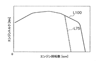
- FIG. 3 shows an engine torque curve representing a torque upper limit value (hereinafter referred to as “torque upper limit value”) that the engine 21 can output according to the rotational speed.
- torque upper limit value a torque upper limit value
- a solid line L100 indicates an engine torque curve when the accelerator operation amount is 100%.
- This engine torque curve corresponds to, for example, the rating of the engine 21 or the maximum power output.
- the accelerator operation amount of 100% means a state in which the accelerator operation member 81a is operated to the maximum.
- a broken line L75 indicates an engine torque curve when the accelerator operation amount is 75%.
- the governor 25 controls the output of the engine 21 so that the output torque of the engine 21 (hereinafter referred to as “engine torque”) is equal to or less than the engine torque curve.
- engine torque the output torque of the engine 21
- the control of the output of the engine 21 is performed by controlling the upper limit value of the fuel injection amount to the engine 21, for example.
- the 1st control part 10a will correct
- the second control unit 10b controls the transmission 26 and the torque converter device 23 according to the traveling state of the vehicle.
- the second control unit 10b automatically performs the shifting of the transmission 26 and the switching of the lockup clutch 27 according to the vehicle speed.
- the second speed torque converter travel means a power transmission state in which the speed stage of the transmission 26 is the second speed and the lock-up clutch 27 is in a non-connected state.
- the second speed lock-up traveling means a power transmission state in which the speed stage of the transmission 26 is the second speed and the lock-up clutch 27 is in a connected state.
- other power transmission states are defined by a combination of the number of speed stages of the transmission 26 and the state of the lockup clutch 27.
- the maximum speed stage is set to the third speed
- the speed change is performed in the range from the second speed torque converter travel to the third speed lockup travel.
- a shift is performed in the range from the second speed torque converter travel to the second speed lockup travel.
- the first speed torque converter travel is set when the maximum speed stage is set to the first speed. It is possible to set the lockup function not to be executed by a lockup function setting member (not shown).
- the second control unit 10b shifts in the order of second speed torque converter travel, third speed torque converter travel, and fourth speed torque converter travel in accordance with the increase in vehicle speed.
- detection signals such as the inlet pressure and the outlet pressure of the torque converter device 23 are also input to the second control unit 10b.
- the first control unit 10a and the second control unit 10b can communicate with each other by wire or wireless.
- Detection signals such as the engine speed, the fuel injection amount, and the accelerator operation amount are input from the first control unit 10a to the second control unit 10b.
- the second controller 10b calculates a correction value for correcting the command value of the engine command signal based on these signals.
- the second control unit 10b transmits a correction command signal corresponding to the correction value to the first control unit 10a.
- This correction value is a value necessary for obtaining a desired reduction amount of the torque upper limit value.
- the 1st control part 10a and the 2nd control part 10b can control a torque upper limit to a desired value.
- the second control unit 10b executes lock-up prohibition control for controlling the lock-up clutch so that the lock-up clutch is in a disconnected state when a predetermined load increase condition is satisfied. Specifically, when the load increase condition is satisfied when the lock-up clutch 27 is in the non-connected state, the lock-up clutch 27 is switched from the non-connected state to the connected state (hereinafter referred to as “lock-up”). The lock-up clutch 27 is maintained in a non-connected state. Further, when the load increase condition is satisfied when the lock-up clutch 27 is in the connected state, the lock-up clutch 27 is switched from the connected state to the non-connected state.
- the predetermined load increase condition is a condition indicating that the work vehicle 1 is in a situation leading to an increase in load on the work implement 3.
- the lock-up prohibition control will be described based on the flowcharts shown in FIGS.
- the flowchart shown in FIG. 4 shows a process for determining whether or not lockup is prohibited in a state where lockup is not prohibited, that is, in a state where a lockup prohibition flag described later is OFF.
- various types of information are detected.
- various information is sent to the first control unit 10a and the second control unit 10b by the various detection signals described above.
- information such as the position of the speed change operation member 85a, the operation amount of the boom operation member 83a and the bucket operation member 84a, and the vehicle speed is sent as a detection signal to the second control unit 10b.
- the work phase is determined. Specifically, the second control unit 10b determines the work situation as follows.
- the second control unit 10b determines a traveling status and a work status of the vehicle based on the detection signal described above.
- the travel status includes “stop”, “forward”, and “reverse”.
- the second control unit 10b determines that the travel status is “stop”.
- the predetermined stop threshold is a value that is low enough that the vehicle can be considered to be stopped.
- Work status includes “loading”, “empty loading”, and “excavation”.
- the second control unit 10b determines that the work status is “load” when the lift cylinder hydraulic pressure is equal to or greater than a predetermined load threshold.
- the second control unit 10b determines that the work status is “empty”. That is, “empty load” means a state where no load is loaded on the bucket 7, and “load” means a state where a load is loaded on the bucket 7. Therefore, the predetermined load threshold value is larger than the lift cylinder hydraulic pressure value in a state where no load is loaded on the bucket 7, and the lift cylinder hydraulic pressure that can be considered that the load is loaded on the bucket 7. Value.
- the second control unit 10b determines that when the lift cylinder hydraulic pressure is equal to or higher than a predetermined excavation hydraulic pressure threshold, the traveling status is “forward”, and the boom angle is equal to or lower than the predetermined excavation angle threshold. It is determined as “digging”. “Excavation” means an operation of pushing the bucket 7 into the earth and lifting it while the vehicle moves forward. Therefore, the excavation hydraulic pressure threshold corresponds to the value of the lift cylinder hydraulic pressure during excavation work.
- the excavation angle threshold corresponds to the value of the boom angle during excavation work.
- the 2nd control part 10b discriminate
- the third step S3 and the fourth step S4 it is determined whether or not the load increasing condition is satisfied. Specifically, in the third step S3, it is determined whether the raising operation amount of the boom operation member 83a is larger than a predetermined operation amount threshold Ath and whether the speed stage of the transmission 26 is the second speed. Here, based on the detection signal from the boom operation detection device 83b, it is determined whether or not the operation amount of the boom operation member 83a is larger than a predetermined operation amount threshold Ath.
- the predetermined operation amount threshold value Ath is, for example, 50%, and is set to a value that is expected to greatly move the boom 6 upward.
- the operation amount when the boom operation member 83a is located at the neutral position is 0%, and the operation amount when the boom operation member 83a is operated to the maximum is 100%. Further, it is determined whether or not the actual speed stage of the transmission 26 is the second speed. When the above conditions are not satisfied, the process proceeds to the fourth step S4.
- the fourth step S4 it is determined whether or not the work phase is excavation.
- the determination is performed based on the determination result of the second step S2.
- the process proceeds to the fifth step S5.
- the lockup prohibition flag is set to ON. That is, the lockup prohibition flag is switched from OFF to ON. Thereby, switching to the connection state of the lockup clutch 27 is prohibited.
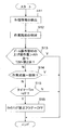
- the flowchart shown in FIG. 5 shows a process for determining whether to release the lockup prohibition in a state where the lockup is prohibited, that is, in a state where the lockup prohibition flag is ON. .
- the processing of the eleventh step S11 and the twelfth step S12 is the same as the first step S1 and the second step S2 described above.
- step S13 and the fourteenth step S14 it is determined whether or not the load increasing condition is satisfied as in the third step S3 and the fourth step S4 described above.
- the process proceeds to step S15.
- the timer Tm In the fifteenth step S15, it is determined whether or not the timer Tm has reached a predetermined time dT.
- the timer Tm starts counting from the point in time when the load increasing conditions in the thirteenth step S13 and the fourteenth step S14 are not satisfied. That is, in the fifteenth step S15, it is determined whether or not a predetermined time dT has elapsed from when the load increasing conditions in the thirteenth step S13 and the fourteenth step S14 are not satisfied.
- the timer Tm reaches the predetermined time, the process proceeds to the 16th step S16.
- the lockup prohibition flag is set to OFF. That is, the lockup prohibition flag is switched from ON to OFF. As a result, the prohibition of switching the lockup clutch 27 to the connected state is released. In this way, the second control unit 10b cancels the prohibition of switching the lockup clutch 27 to the connected state when a predetermined time elapses from the time when the load increase condition is no longer satisfied.
- the flowchart shown in FIG. 6 shows whether or not the second control unit 10b switches the lock-up clutch 27 from the non-connected state to the connected state based on the traveling state of the vehicle when the lock-up clutch 27 is in the non-connected state.
- the process for performing the determination is shown.
- step S31 various types of information are detected.
- information relating to the vehicle speed and the lockup prohibition flag is detected.
- 32nd step S32 it is determined whether or not the vehicle speed is equal to or higher than a predetermined switching speed Vth.
- the switching speed Vth is a vehicle speed when switching from torque converter travel to lockup travel, and a value is set for each speed stage of the transmission 26.
- the process proceeds to 35th step S35, and the lockup clutch 27 is maintained in the non-connected state.
- the process proceeds to the 33rd step S33.
- the process proceeds to 34th step S34, and the lockup clutch 27 is switched from the non-connected state to the connected state.
- the process proceeds to the 35th step S35, and the lockup clutch 27 is maintained in the non-connected state. That is, even when the vehicle speed has reached the switching speed, when the lockup prohibition flag is ON, switching of the lockup clutch 27 to the connected state is prohibited.
- the lockup clutch 27 when the lockup clutch 27 is in the connected state, the same processing as in FIG. 6 is performed when it is determined whether or not the lockup clutch 27 is switched from the connected state to the non-connected state. Specifically, when the vehicle speed is lower than the switching speed Vth in the 32nd step S32, the lockup clutch 27 is switched from the connected state to the disconnected state in the 35th step S35. If the vehicle speed is equal to or higher than the switching speed Vth in the 32nd step S32 and the lockup prohibition flag is OFF in the 33rd step S33, the lockup clutch 27 is maintained in the connected state in the 34th step S34.
- the lockup clutch 27 is disconnected from the connected state in the 35th step S35. Switch to state. That is, when the lockup clutch 27 is in the connected state, when the lockup prohibition flag is switched from OFF to ON, the lockup clutch 27 is switched from the connected state to the non-connected state. It should be noted that the switching speed when the lockup clutch 27 is switched from the connected state to the disconnected state may be different from the switching speed when the lockup clutch 27 is switched from the nonconnected state to the connected state.
- FIG. 7A shows the state of the lock-up clutch 27, that is, whether the lock-up clutch 27 is in a connected state (ON) or a non-connected state (OFF).
- FIG. 7B shows changes in vehicle speed.
- FIG.7 (c) has shown the raising operation amount of the boom operation member 83a.
- FIG. 7D shows a lockup prohibition flag. Further, it is assumed that the speed stage of the transmission 26 is fixed at the second speed.
- the vehicle speed is 0, and then the vehicle speed increases.
- the power transmission state of the work vehicle 1 is the second speed torque converter traveling.
- the lockup clutch 27 is switched from the non-connected state to the connected state.
- the raising operation amount of the boom operation member 83a reaches the operation threshold value Ath at time t2
- the above-described load increase condition is satisfied.
- the lockup prohibition flag is set to ON by the lockup prohibition control.
- the lockup clutch 27 is switched from the connected state to the non-connected state.
- the V-shaping work is a work in which the work vehicle 1 lifts the load 100 such as earth and sand little by little by the work machine 3 and loads it on the loading position 200 such as a dump truck.
- the shift operation member 85a is set to the second speed position because the movement at a relatively short distance is repeated.
- the work vehicle 1 moves toward the luggage 100.
- the work phase is “empty forward”.
- the work vehicle 1 thrusts into the luggage 100 and lifts the luggage 100 by the bucket 7.
- the work phase is “digging”.
- the operator switches the FR operation member 86a from the forward movement position to the reverse movement position.
- the work vehicle 1 moves backward with the luggage 100 placed on the bucket 7.
- the work phase is “backward loading”.
- the operator switches the FR operation member 86a from the reverse position to the forward position.
- the work vehicle 1 moves forward toward the loading position 200 with the load 100 placed on the bucket 7.
- the work phase is “load advance”.
- the load 100 on the bucket 7 is lowered to the loading position 200.
- the work phase at this time is referred to as “soil removal”.
- the operator switches the FR operation member 86 a from the forward movement position to the reverse movement position, and the work vehicle 1 moves backward and leaves the loading position 200.
- the work phase is “unloading backward”.
- the operator switches the FR operation member 86a from the reverse drive position to the forward drive position, and moves forward toward the luggage 100 again.
- FIG. 9A shows the state of the lockup clutch 27.
- FIG. 9B shows changes in vehicle speed.
- FIG. 9C shows the raising operation amount of the boom operation member 83a.
- FIG. 9D shows a lockup prohibition flag.
- the work vehicle 1 moves forward toward the load 100 at the time of an empty load advance (time point T0-T2). For this reason, the operation of the boom 6 is not performed, and the vehicle speed gradually increases.
- the lock-up clutch 27 is in a disconnected state (time point T0-T1). Further, since the load increase condition described above is not satisfied, the lockup prohibition flag is OFF, and the lockup prohibition is released. Therefore, when the vehicle speed exceeds the switching speed Vth, the lock-up clutch 27 is switched to the connected state (time point T1-T2).
- time T3-T6 When moving backward (time T3-T6), the work vehicle 1 moves backward with the load 100 placed on the bucket 7. For this reason, the vehicle speed gradually increases while the boom 6 is maintained at a low position. At this time, until the vehicle speed reaches the switching speed Vth, the lock-up clutch 27 is in a disconnected state (time T3-T5). Note that the lockup prohibition flag is set to OFF after time T4 when time dT elapses from time T3 when the load increase condition is no longer satisfied, and the lockup prohibition is released. Accordingly, when the vehicle speed exceeds the switching speed Vth, the lockup clutch 27 is switched to the connected state (time T5-T6).
- the operator operates the bucket operating member 84a while the work vehicle 1 moves slowly, and lowers the load 100 on the bucket 7 to the loading position 200. Also at this time, if the above-described load increase condition is satisfied, the lockup prohibition flag is ON, and lockup is prohibited. If the vehicle speed is lower than the switching speed Vth, the lockup clutch 27 is maintained in the disconnected state even if the load increase condition is satisfied.
- One of the conditions for increasing the load is that the work phase of the work implement 3 is excavation.
- the other condition for increasing the load is that the raising operation amount of the boom operation member 83a is larger than a predetermined operation amount threshold, and the actual speed stage of the transmission 26 is the second speed. Lock-up is prohibited when at least one of these load increase conditions is met. Alternatively, the lockup clutch 27 is switched from the connected state to the non-connected state.
- These load increase conditions indicate that the work vehicle is in a state where the load applied to the work implement 3 is expected to increase. For this reason, lockup can be prohibited before the load applied to the work machine 3 increases.
- the lockup clutch 27 is switched from the connected state to the non-connected state before the load on the work machine 3 increases. Thereby, when the load concerning the work machine 3 increases, it can suppress that workability
- the predetermined time dt may be set to a time that can suppress frequent switching of the lockup clutch 27.
- the time may be about several seconds.
- the load increase condition is not limited to the above-described conditions, and other conditions may be used as long as they lead to an increase in the load on the work machine 3.
- the load increase condition may include that the vehicle speed is equal to or lower than a predetermined speed threshold. Specifically, it may be determined that the vehicle speed is equal to or lower than a predetermined speed threshold instead of the condition that the speed stage of the transmission 26 is the second speed among the above-described load increase conditions.
- the predetermined speed threshold is set to a value that is assumed that the work vehicle 1 is traveling at a high speed and the driving of the traveling device 22 is more important than the work implement 3.
- the predetermined speed threshold is larger than the switching speed of the lockup clutch 27.
- the speed stage of the transmission 26 may be a low speed stage suitable for work.
- the low speed stage suitable for the work is preferably the second speed as in the above embodiment.
- the third speed may be the low speed stage suitable for work.
- the following conditions may be used. These conditions also indicate that the work vehicle is in a state that leads to an increase in the load on the work machine 3, or that an operation that leads to an increase in the load on the work machine 3 has been performed.
- the boom angle is larger than a predetermined boom angle threshold. That is, the height of the bucket is higher than a predetermined height threshold.
- the work phase is cargo.
- the bucket angle is larger than a predetermined bucket angle threshold.
- the raising operation amount of the bucket operation member 84a is larger than a predetermined operation threshold.
- the maximum speed stage is a low speed stage suitable for work.
- the second speed is preferable as the low speed stage suitable for the operation (5).
- the low speed stage suitable for the work may be the third speed depending on the setting of the speed stage number of the transmission 26 and the gear ratio.
- the low speed stage suitable for the work may be a condition of the second speed or lower (second speed and first speed).
- the load increase condition may be determined based on the operating status of the work implement pump 13 or the steering pump 12 (for example, pump hydraulic pressure, swash plate angle, flow rate, cylinder speed).
- the operation amount of work implement operation members such as the boom operation member 83a and the bucket operation member 84a, not only a raising operation amount but a lowering operation amount may be used for determination of load increase conditions.
- the first control unit 10a and the second control unit 10b are provided separately, but may be provided integrally.
- the functions of the first control unit 10a and the second control unit 10b may be realized by one computer.
- the functions of the first control unit 10a or the second control unit 10b may be shared by a plurality of computers.
- the various operation members described above are not limited to members such as pedals or levers as illustrated.
- a dial, a switch, or the like may be used.
- the switching of the lock-up clutch 27 when the lock-up is not prohibited may be determined based on other parameters as well as the vehicle speed.
- the configuration of the work machine 3 is not limited to the bucket 7 and the boom 6, and other members may be used.
- another work attachment may be attached to the boom 6 instead of the bucket 7.
- the speed stage of the transmission 26 is not limited to the first speed to the fourth speed. There may be more or fewer speed stages capable of shifting. Further, the shift pattern of the transmission 26 by the second control unit 10b is not limited to that described above. For example, the shift may be performed sequentially from the first speed in accordance with the increase in speed.
Landscapes
- Engineering & Computer Science (AREA)
- General Engineering & Computer Science (AREA)
- Mechanical Engineering (AREA)
- Mining & Mineral Resources (AREA)
- Civil Engineering (AREA)
- Structural Engineering (AREA)
- Control Of Fluid Gearings (AREA)
- Control Of Transmission Device (AREA)
- Operation Control Of Excavators (AREA)
Abstract
本発明の課題は、作業車両において、作業性の低下を抑えると共に、燃費を向上させることにある。本発明の作業車両では、制御部は、車両の走行状態に応じてロックアップクラッチを連結状態と非連結状態とに切り換える。制御部は、作業機にかかる負荷の増大につながる負荷増大条件が満たされているか否かを判定する。そして、制御部は、負荷増大条件が満たされているときは、ロックアップクラッチが非連結状態であるように、ロックアップクラッチを制御する。
Description
本発明は、作業車両及び作業車両の制御方法に関する。
ホイールローダなどの作業車両は、エンジンからの駆動力によって走行装置と油圧ポンプが駆動される。走行装置が駆動されることにより、車両が走行する。また、油圧ポンプが駆動されることにより、作動油が油圧ポンプから作業機に供給される。これにより、作業機が駆動される。
また、作業車両には、トルクコンバータとロックアップクラッチとを有するトルクコンバータ装置を備えるものがある。トルクコンバータ装置は、ロックアップクラッチが非連結状態であるときは、エンジンからの駆動力をトルクコンバータを介して走行装置に伝達する(以下、この状態を「トルコン走行」と呼ぶ)。また、ロックアップクラッチが連結状態であるときは、トルクコンバータ装置は、エンジンからの駆動力をロックアップクラッチを介して走行装置に伝達する(以下、この状態を「ロックアップ走行」と呼ぶ)。また、ロックアップクラッチの連結状態と非連結状態との切換は、制御部によって自動的に行われる。制御部は、車両の走行状態に応じてロックアップクラッチを非連結状態と連結状態とのいずれかに切り換える。例えば、制御部は、車速が所定の切換速度に達すると、ロックアップクラッチを非連結状態から連結状態に切り換える(特許文献1参照)。
上記のような作業車両では、走行のみを行うのではなく、走行しながら作業機を駆動することがある。このような状態で、ロックアップクラッチが連結状態になると、エンジンの回転数が低下することにより、油圧ポンプからの作動油の吐出量も低下してしまう。この場合、作業機の動作が遅くなり、作業性が低下してしまう。
また、上記のような作業性の低下を避けるために、オペレータは、スイッチなどの操作により、制御部によるロックアップクラッチの切換制御を無効にしている。従って、ロックアップ走行は、トルコン走行よりも燃費低減の効果が高いにも関わらず、上記のような作業中にはロックアップ走行が有効に利用されていないのが実情である。
本発明の課題は、作業車両において、作業性の低下を抑えると共に、燃費を向上させることにある。
本発明の第1の態様に係る作業車両は、エンジンと、走行装置と、油圧ポンプと、作業機と、トルクコンバータ装置と、制御部とを備える。走行装置は、エンジンからの駆動力により駆動されて車両を走行させる。油圧ポンプは、エンジンからの駆動力により駆動されて作動油を吐出する。作業機は、油圧ポンプからの作動油により駆動される。トルクコンバータ装置は、トルクコンバータとロックアップクラッチとを有し、エンジンからの駆動力を走行装置に伝達する。制御部は、車両の走行状態に応じてロックアップクラッチを連結状態と非連結状態とに切り換える。制御部は、作業機への負荷の増大につながる負荷増大条件が満たされているか否かを判定する。そして、制御部は、負荷増大条件が満たされているときは、ロックアップクラッチが非連結状態であるようにロックアップクラッチを制御する。
この作業車両では、作業機に大きな負荷がかかる作業局面において、ロックアップクラッチが非連結状態であるようにロックアップクラッチが制御される。従って、作業車両は、ロックアップクラッチが非連結状態である状態で作業機による作業を行うことができる。これにより、ロックアップクラッチが連結状態である状態で作業が行われる場合と比べて、作業機による作業性が低下することを抑えることができる。また、作業機に大きな負荷がかからない作業局面においては、ロックアップ走行が活用されることにより、燃費を向上させることができる。
本発明の第2の態様に係る作業車両は、第1の態様に係る作業車両であって、制御部は、ロックアップクラッチが非連結状態である場合に負荷増大条件が満たされているときは、ロックアップクラッチの連結状態への切換を禁止して、ロックアップクラッチを非連結状態に維持する。
この作業車両では、作業機に大きな負荷がかかる作業局面において、ロックアップクラッチの連結状態への切換が禁止されて、ロックアップクラッチが非連結状態に維持される。従って、ロックアップクラッチの連結状態への切り換えを判定するための他の条件が満たされたとしても、ロックアップクラッチが非連結状態に維持される。このため、作業車両は、ロックアップクラッチが非連結状態である状態で作業機による作業を行うことができる。これにより、作業機による作業性が低下することを抑えることができる。
本発明の第3の態様に係る作業車両は、第1の態様に係る作業車両であって、制御部は、ロックアップクラッチが連結状態である場合に負荷増大条件が満たされたときは、ロックアップクラッチを連結状態から非連結状態に切り換える。
この作業車両では、作業機に大きな負荷がかかる作業局面において、ロックアップクラッチが連結状態から非連結状態に切り換えられる。従って、作業機に大きな負荷がかからない作業局面においてロックアップクラッチが連結状態であったとしても、作業機に大きな負荷がかかる作業局面に変わったときには、作業車両は、ロックアップクラッチが非連結状態である状態で作業機による作業を行うことができる。これにより、作業機による作業性が低下することを抑えることができる。
本発明の第4の態様に係る作業車両は、第1の態様に係る作業車両であって、作業機を操作するための作業機操作部材と、作業機操作部材の操作量を検出する作業機操作検出部と、をさらに備える。負荷増大条件は、作業機操作部材の操作量が所定の操作量閾値より大きいことを含む。
作業機操作部材の操作量が所定の操作量閾値より大きいことは、作業車両が、作業機への負荷が増大することが予想される状態であることを示している。このため、作業機への負荷が増大する事前に、ロックアップクラッチの連結状態への切換を禁止することができる。或いは、作業機への負荷が増大する事前に、ロックアップクラッチを連結状態から非連結状態へ切り換えることができる。これにより、作業機への負荷が増大したときに、作業機による作業性が低下することを抑えることができる。
本発明の第5の態様に係る作業車両は、第4の態様に係る作業車両であって、作業機は、作業機操作部材の操作に応じて上下に揺動するブームと、ブームの先端に取り付けられる作業アタッチメントと、を有する。
この作業車両では、作業機操作部材が操作されると、その後、ブームが上下に移動する。このとき、作業機には大きな負荷がかかる。特に、作業機操作部材の操作量が大きいほど、作業機に大きな負荷がかかる。従って、この作業車両では、作業機の負荷が増大することを事前に精度よく予測してロックアップクラッチを制御することができる。これにより、作業機への負荷が増大したときに、作業機による作業性が低下することを抑えることができる。
本発明の第6の態様に係る作業車両は、第1の態様に係る作業車両であって、負荷増大条件は、作業車両の作業局面が掘削であることを含む。
作業車両の作業局面が掘削であることは、作業車両が、作業機への負荷が増大することが予想される状態であることを示している。このため、作業機への負荷が増大することを事前に精度よく予測して、ロックアップクラッチを制御することができる。これにより、作業機への負荷が増大したときに、作業機による作業性が低下することを抑えることができる。
本発明の第7の態様に係る作業車両は、第4の態様に係る作業車両であって、走行装置は、第1速から第3速以上の速度段に変速可能なトランスミッションを有する。負荷増大条件は、トランスミッションの速度段が第2速であることをさらに含む。
この作業車両では、トランスミッションの速度段が第2速であることが負荷増大条件に含まれる。作業車両では、作業機を用いた作業を行うときには、トランスミッションの速度段が第2速であることが多い。このため、作業機による作業性が低下することを抑えることができる。
本発明の第8の態様に係る作業車両は、第4の態様に係る作業車両であって、車速を検出する車速検出部をさらに備える。負荷増大条件は、車速が所定の速度閾値以下であることをさらに含む。
作業車両が、作業機への負荷が増大することが予想される状態であるか否かは、車速によっても判定することができる。車速が所定の速度閾値より大きいとき、すなわち、車両が高速で走行しているときは、作業機よりも走行装置の駆動が重視されるからである。逆に車両が低速で走行しているときは、走行装置よりも作業機の駆動が重視される。従って、この作業車両では、作業機による作業性が低下することを抑えることができる。
本発明の第9の態様に係る作業車両は、第2の態様に係る作業車両であって、制御部は、負荷増大条件が満たされなくなった時点から所定時間経過したときに、ロックアップクラッチの連結状態への切換の禁止を解除する。
この作業車両では、負荷増大条件が満たされなくなった時点で直ちにロックアップクラッチの連結状態への切換が実行されることが防止される。これにより、ロックアップクラッチの切換が短時間のうちに繰り返されることを防止することができる。
本発明の第10の態様に係る作業車両の制御方法は、エンジンと、走行装置と、油圧ポンプと、作業機と、トルクコンバータ装置と、制御部とを備える作業車両の制御方法である。この制御方法は、次のステップを備える。車両の走行状態に応じてロックアップクラッチを連結状態と非連結状態とに切り換えるステップ。作業機への負荷の増大につながる負荷増大条件が満たされているか否かを判定するステップ。負荷増大条件が満たされているときは、ロックアップクラッチが非連結状態であるようにロックアップクラッチを制御するステップ。
この作業車両の制御方法では、作業機に大きな負荷がかかる作業局面において、ロックアップクラッチが非連結状態であるようにロックアップクラッチが制御される。これにより、ロックアップクラッチが連結状態である状態で作業が行われる場合と比べて、作業機による作業性が低下することを抑えることができる。また、作業機に大きな負荷がかからない作業局面においては、ロックアップ走行が活用されることにより、燃費を向上させることができる。
本発明では、作業車両において、作業性の低下を抑えると共に、燃費を向上させることができる。
本発明の一実施形態に係る作業車両1を図1および図2に示す。図1は、作業車両1の外観図であり、図2は、作業車両1の構成を示す模式図である。この作業車両1は、ホイールローダであり、作業車両1は、前輪4a及び後輪4bが回転駆動されることにより自走可能であると共に作業機3を用いて所望の作業を行うことができる。
図1に示すように、この作業車両1は、車体フレーム2、作業機3、前輪4a、後輪4b、運転室5を備えている。
車体フレーム2は、前車体部2aと後車体部2bとを有している。前車体部2aと後車体部2bとは互いに左右方向に揺動可能に連結されている。前車体部2aと後車体部2bとに渡って一対のステアリングシリンダ11a、11bが設けられている。ステアリングシリンダ11a、11bは、ステアリングポンプ12(図2参照)からの作動油によって駆動される油圧シリンダである。ステアリングシリンダ11a、11bが伸縮することによって、前車体部2aが後車体部2bに対して揺動する。これにより、車両の進行方向が変更される。なお、図1及び図2では、ステアリングシリンダ11a、11bの一方のみを図示しており他方を省略している。
前車体部2aには、作業機3および一対の前輪4aが取り付けられている。作業機3は、作業機ポンプ13(図2参照)からの作動油によって駆動される。作業機3は、ブーム6と、一対のリフトシリンダ14a、14bと、バケット7と、バケットシリンダ15とを有する。ブーム6は、前車体部2aに装着されている。リフトシリンダ14a、14bの一端は前車体部2aに取り付けられている。リフトシリンダ14a、14bの他端はブーム6に取り付けられている。リフトシリンダ14a、14bが作業機ポンプ13からの作動油によって伸縮することによって、後述するブーム操作部材83aの操作に応じてブーム6が上下に揺動する。なお、図1及び図2では、リフトシリンダ14a、14bのうちの一方のみを図示しており、他方は省略している。バケット7は、ブーム6の先端に取り付けられている。バケットシリンダ15の一端は前車体部2aに取り付けられている。バケットシリンダ15の他端はベルクランク9を介してバケット7に取り付けられている。バケットシリンダ15が、作業機ポンプ13からの作動油によって伸縮することによって、バケット操作部材84aの操作に応じてバケット7が上下に揺動する。
後車体部2bには、運転室5及び一対の後輪4bが取り付けられている。運転室5は、車体フレーム2の上部に載置されており、オペレータが着座するシートや、後述する操作部8などが内装されている。
また、図2に示すように、作業車両1は、エンジン21、トルクコンバータ装置23、走行装置22、作業機ポンプ13、ステアリングポンプ12、操作部8、制御部10などを備えている。
エンジン21は、ディーゼルエンジンであり、シリンダ内に噴射する燃料量を調整することによりエンジン21の出力が制御される。この調整は、エンジン21の燃料噴射ポンプ24に付設された電子ガバナ25が後述する第1制御部10aによって制御されることで行われる。ガバナ25としては、一般的にオールスピード制御方式のガバナが用いられ、エンジン回転数が、後述するアクセル操作量に応じた目標回転数となるように、負荷に応じてエンジン回転数と燃料噴射量とを調整する。すなわち、ガバナ25は目標回転数と実際のエンジン回転数との偏差がなくなるように燃料噴射量を増減する。エンジン回転数は、エンジン回転数センサ91によって検出される。エンジン回転数センサ91の検出信号は、第1制御部10aに入力される。
トルクコンバータ装置23は、ロックアップクラッチ27とトルクコンバータ28を有している。ロックアップクラッチ27は、連結状態と非連結状態とに切換可能である。ロックアップクラッチ27が非連結状態である場合には、トルクコンバータ28が、オイルを媒体としてエンジン21からの駆動力を走行装置22に伝達する(以下、この状態を「トルコン走行」と呼ぶ)。ロックアップクラッチ27が連結状態である場合には、トルクコンバータ28の入力側と出力側とが直結される。エンジン21からの駆動力はロックアップクラッチ27を介して走行装置22に伝達される(以下、この状態を「ロックアップ走行」と呼ぶ)。ロックアップクラッチ27は、油圧作動式のクラッチであり、ロックアップクラッチ27への作動油の供給がクラッチ制御弁31を介して後述する第2制御部10bによって制御されることにより、連結状態と非連結状態とが切り換えられる。
走行装置22は、エンジン21からの駆動力により車両を走行させる装置である。走行装置22は、トランスミッション26、及び上述した前輪4a及び後輪4bなどを有する。
トランスミッション26は、前進走行段に対応する前進クラッチCFと、後進走行段に対応する後進クラッチCRとを有している。各クラッチCF、CRの連結状態・非連結状態が切り換えられることによって、車両の前進と後進とが切り換えられる。クラッチCF、CRが共に非連結状態のときは、車両は中立状態となる。また、トランスミッション26は、複数の速度段に対応した複数の速度段クラッチC1-C4を有しており、減速比を複数段階に切り換えることができる。例えば、このトランスミッション26では、4つの速度段クラッチC1-C4が設けられており、速度段を第1速から第4速までの4段階に切り換えることができる。各速度段クラッチC1-C4は、油圧作動式の油圧クラッチである。図示しない油圧ポンプからクラッチ制御弁31を介してクラッチC1-C4へ作動油が供給される。クラッチ制御弁31が第2制御部10bによって制御されて、クラッチC1-C4への作動油の供給が制御されることにより、各クラッチC1-C4の連結状態及び非連結状態が切り換えられる。
トランスミッション26の出力軸には、トランスミッション26の出力軸の回転数を検出するT/M出力回転数センサ92が設けられている。T/M出力回転数センサ92からの検出信号は、第2制御部10bに入力される。第2制御部10bは、T/M出力回転数センサ92の検出信号に基づいて車速を算出する。従って、T/M出力回転数センサ92は車速を検出する車速検出部として機能する。なお、トランスミッション26の出力軸ではなく他の部分の回転速度を検出するセンサが車速検出部として用いられてもよい。トランスミッション26から出力された駆動力は、シャフト32などを介して前輪4a及び後輪4bに伝達される。これにより、車両が走行する。トランスミッション26の入力軸の回転数は、T/M入力回転数センサ93によって検出される。T/M入力回転数センサ93からの検出信号は、第2制御部10bに入力される。
エンジン21の駆動力の一部は、PTO軸33を介して作業機ポンプ13及びステアリングポンプ12に伝達される。作業機ポンプ13及びステアリングポンプ12は、エンジン21からの駆動力によって駆動される油圧ポンプである。作業機ポンプ13から吐出された作動油は、作業機制御弁34を介してリフトシリンダ14a、14b及びバケットシリンダ15に供給される。また、ステアリングポンプ12から吐出された作動油は、ステアリング制御弁35を介してステアリングシリンダ11a、11bに供給される。このように、作業機3は、エンジン21からの駆動力の一部によって駆動される。
作業機ポンプ13から吐出された作動油の圧力(以下、「作業機ポンプ油圧」と呼ぶ)は、第1油圧センサ94によって検出される。リフトシリンダ14a、14bに供給される作動油の圧力(以下「リフトシリンダ油圧」と呼ぶ)は、第2油圧センサ95によって検出される。具体的には、第2油圧センサ95は、リフトシリンダ14a、14bを伸長させるときに作動油が供給されるシリンダヘッド室の油圧を検出する。バケットシリンダ15に供給される作動油の圧力(以下「バケットシリンダ油圧」と呼ぶ)は、第3油圧センサ96によって検出される。具体的には、第3油圧センサ96は、バケットシリンダ15を伸長させるときに作動油が供給されるシリンダヘッド室の油圧を検出する。ステアリングポンプ12から吐出された作動油の圧力(以下、「ステアリングポンプ油圧」と呼ぶ)は、第4油圧センサ97によって検出される。第1~第4油圧センサ94-97からの検出信号は、第2制御部10bに入力される。
操作部8は、オペレータによって操作される。操作部8は、アクセル操作部材81a、アクセル操作検出装置81b、ステアリング操作部材82a、ステアリング操作検出装置82b、ブーム操作部材83a、ブーム操作検出装置83b、バケット操作部材84a、バケット操作検出装置84b、変速操作部材85a、変速操作検出装置85b、FR操作部材86a、及び、FR操作検出装置86bなどを有する。
アクセル操作部材81aは、例えばアクセルペダルであり、エンジン21の目標回転数を設定するために操作される。アクセル操作検出装置81bは、アクセル操作部材81aの操作量(以下、「アクセル操作量」と呼ぶ)を検出する。アクセル操作検出装置81bは、検出信号を第1制御部10aへ出力する。
ステアリング操作部材82aは、例えばステアリングハンドルであり、車両の進行方向を操作するために操作される。ステアリング操作検出装置82bは、ステアリング操作部材82aの位置を検出し、検出信号を第2制御部10bに出力する。第2制御部10bは、ステアリング操作検出装置82bからの検出信号に基づいてステアリング制御弁35を制御する。これにより、ステアリングシリンダ11a、11bが伸縮して、車両の進行方向が変更される。
ブーム操作部材83a及びバケット操作部材84a(作業機操作部材)は、例えば操作レバーであり、作業機3を動作させるために操作される。具体的には、ブーム操作部材83aは、ブーム6を動作させるために操作される。バケット操作部材84aは、バケット7を動作させるために操作される。ブーム操作検出装置83b(作業機操作検出部)は、ブーム操作部材83aの位置を検出する。これにより、ブーム操作部材83aの操作量が検出される。バケット操作検出装置84b(作業機操作検出部)は、バケット操作部材84aの位置を検出する。これにより、バケット操作部材84aの操作量が検出される。ブーム操作検出装置83b及びバケット操作検出装置84bは、検出信号を第2制御部10bに出力する。第2制御部10bは、ブーム操作検出装置83b及びバケット操作検出装置84bからの検出信号に基づいて作業機制御弁34を制御する。これにより、リフトシリンダ14a、14b及びバケットシリンダ15が伸縮して、ブーム6及びバケット7が動作する。また、作業機3にはブーム角を検出するブーム角検出装置98とバケット角を検出するバケット角検出装置99が設けられている。ブーム角は、例えば、ブーム6の後端部と前端部とを結ぶ方向の水平方向に対する角度である。ブーム角検出装置98は、検出信号を第2制御部10bに出力する。バケット角は、例えばバケット7の刃先に沿った方向の水平方向に対する角度である。バケット角検出装置99は、検出信号を第2制御部10bに出力する。
変速操作部材85aは、例えばシフトレバーである。変速操作部材85aは、速度段の上限(以下、「最大速度段」と呼ぶ)を設定するために操作される。変速操作検出装置85bは、変速操作部材85aの位置を検出する。変速操作検出装置85bは、検出信号を第2制御部10bに出力する。第2制御部10bは、変速操作検出装置85bからの検出信号に基づいて、トランスミッション26の変速を制御する。
FR操作部材86aは、車両の前進と後進とを切り換えるために操作される。FR操作部材86aは、前進、中立、及び後進の各位置に切り換えられる。FR操作検出装置86bは、FR操作部材86aの位置を検出する。FR操作検出装置86bは、検出信号を第2制御部10bに出力する。第2制御部10bは、FR操作検出装置86bからの検出信号に基づいてクラッチ制御弁31を制御する。これにより、前進クラッチCF及び後進クラッチCRが制御され、車両の前進と後進と中立状態とが切り換えられる。
制御部10は、第1制御部10a及び第2制御部10bを有する。第1制御部10a及び第2制御部10bは、例えばプログラムメモリやワークメモリとして使用される記憶装置と、プログラムを実行するCPUと、を有するコンピュータにより、それぞれ実現されることができる。
第1制御部10aは、アクセル操作量に応じた目標回転数が得られるように、エンジン指令信号をガバナ25に送る。図3に、エンジン21が回転数に応じて出力できるトルク上限値(以下、「トルク上限値」と呼ぶ)を表すエンジントルクカーブを示す。図3において、実線L100は、アクセル操作量が100%であるときのエンジントルクカーブを示している。このエンジントルクカーブは、例えばエンジン21の定格又は最大のパワー出力に相当する。なお、アクセル操作量が100%とは、アクセル操作部材81aが最大に操作されている状態を意味する。また、破線L75は、アクセル操作量が75%であるときのエンジントルクカーブを示している。ガバナ25は、エンジン21の出力トルク(以下、「エンジントルク」と呼ぶ)がエンジントルクカーブ以下となるようにエンジン21の出力を制御する。このエンジン21の出力の制御は、例えば、エンジン21への燃料噴射量の上限値を制御することにより行われる。なお、第1制御部10aは、第2制御部10bから後述する修正指令信号を受信すると、修正指令信号によりエンジン指令信号の指令値を修正してガバナ25に送る。
第2制御部10bは、車両の走行状態に応じて、トランスミッション26やトルクコンバータ装置23を制御する。第2制御部10bは、車速に応じて、トランスミッション26の変速およびロックアップクラッチ27の切換を自動的に行う。具体的には、車速の増大に応じて、第2速トルコン走行、第2速ロックアップ走行、第3速トルコン走行、第3速ロックアップ走行、第4速トルコン走行及び第4速ロックアップ走行の順に変速を行う。例えば、第2速トルコン走行は、トランスミッション26の速度段が第2速であり、且つ、ロックアップクラッチ27が非連結状態である動力伝達状態を意味する。また、第2速ロックアップ走行は、トランスミッション26の速度段が第2速であり、且つ、ロックアップクラッチ27が連結状態である動力伝達状態を意味する。他の動力伝達状態についても同様に、トランスミッション26の速度段数とロックアップクラッチ27の状態との組み合わせによって定義される。ただし、最高速度段が第3速に設定されているときは、第2速トルコン走行から第3速ロックアップ走行までの範囲で変速が行われる。最高速度段が第2速に設定されているときは、第2速トルコン走行から第2速ロックアップ走行までの範囲で変速が行われる。第1速トルコン走行は、最高速度段が第1速に設定されているときに設定される。なお、図示しないロックアップ機能設定部材によって、ロックアップ走行が実行されないように設定することが可能である。また、後述するロックアップ禁止制御によりロックアップが禁止されているときには、ロックアップ走行は実行されない。これらの場合、第2制御部10bは、車速の増大に応じて、第2速トルコン走行、第3速トルコン走行、及び第4速トルコン走行の順に変速を行う。
第2制御部10bには、上述した検出信号に加えて、トルクコンバータ装置23の入口圧及び出口圧などの検出信号も入力される。また、第1制御部10aと第2制御部10bとは有線又は無線によって互いに通信することができる。エンジン回転数、燃料噴射量、アクセル操作量などの検出信号が第1制御部10aから第2制御部10bに入力される。第2制御部10bは、これらの信号に基づいて、エンジン指令信号の指令値を修正するための修正値を算出する。第2制御部10bは、修正値に対応する修正指令信号を第1制御部10aへ送信する。この修正値は、トルク上限値の所望の低減量を得るために必要な値である。これにより、第1制御部10aと第2制御部10bとは、トルク上限値を所望の値に制御することができる。
第2制御部10bは、所定の負荷増大条件が満たされているときは、ロックアップクラッチが非連結状態であるようにロックアップクラッチを制御するロックアップ禁止制御を実行する。具体的には、ロックアップクラッチ27が非連結状態である場合に負荷増大条件が満たされているときは、ロックアップクラッチ27の非連結状態から連結状態への切換(以下、「ロックアップ」と呼ぶ)を禁止してロックアップクラッチ27を非連結状態に維持する。また、ロックアップクラッチ27が連結状態である場合に負荷増大条件が満たされたときは、ロックアップクラッチ27を連結状態から非連結状態に切り換える。所定の負荷増大条件とは、作業車両1が作業機3への負荷の増大につながる状況にあることを示す条件である。以下、ロックアップ禁止制御について図4から図6に示すフローチャートに基づいて説明する。
図4に示すフローチャートは、ロックアップが禁止されていない状態、すなわち後述するロックアップ禁止フラグがOFFである状態において、ロックアップを禁止するか否かの判定を行うための処理を示している。
第1ステップS1では、各種の情報が検出される。ここでは、上述した各種の検出信号によって、第1制御部10a及び第2制御部10bに各種の情報が送られる。例えば、変速操作部材85aの位置、ブーム操作部材83a及びバケット操作部材84aの操作量、車速などの情報が検出信号として第2制御部10bに送られる。
第2ステップS2では、作業局面の判別が行われる。具体的には、第2制御部10bは、以下のようにして作業局面を判別する。
まず、第2制御部10bは、上述した検出信号に基づいて、車両の走行ステータスと作業ステータスとを判別する。走行ステータスには、「停止」、「前進」、及び「後進」がある。車速が所定の停止閾値以下である場合には、第2制御部10bは、走行ステータスを「停止」と判定する。所定の停止閾値は、車両が停止していると見なすことができる程度に低い値である。FR操作部材86aが前進位置に設定されており、且つ、車両が前進している場合には、第2制御部10bは、走行ステータスを「前進」と判定する。FR操作部材86aが後進位置に設定されており、且つ、車両が後進している場合には、第2制御部10bは、走行ステータスを「後進」と判定する。
作業ステータスには、「積荷」、「空荷」、及び、「掘削」がある。第2制御部10bは、リフトシリンダ油圧が所定の積荷閾値以上である場合には、作業ステータスを「積荷」と判定する。第2制御部10bは、リフトシリンダ油圧がこの積荷閾値より小さい場合には、作業ステータスを「空荷」と判定する。すなわち、「空荷」とは、バケット7に荷物が積まれていない状態を意味し、「積荷」とは、バケット7に荷物が積まれている状態を意味する。従って、所定の積荷閾値は、バケット7に荷物が積まれていない状態でのリフトシリンダ油圧の値よりも大きな値であり、バケット7に荷物が積まれていると見なすことができるリフトシリンダ油圧の値である。また、第2制御部10bは、リフトシリンダ油圧が所定の掘削油圧閾値以上であり、且つ、走行ステータスが「前進」であり、且つ、ブーム角が所定の掘削角度閾値以下である場合に、「掘削」と判定する。「掘削」は、車両が前進しながらバケット7を土砂に突っ込んで持ち上げる作業を意味する。従って、掘削油圧閾値は、掘削作業中のリフトシリンダ油圧の値に相当する。また、掘削角度閾値は、掘削作業中のブーム角の値に相当する。第2制御部10bは、上記の走行ステータスと作業ステータスとの組み合わせにより、作業局面を判別する。具体的には、作業局面は、「空荷停止」、「積荷停止」「空荷前進」、「積荷前進」、「空荷後進」、「積荷後進」、「掘削」の7つの局面に判別される。
第3ステップS3及び第4ステップS4では、負荷増大条件が満たされているか否かが判定される。具体的には、第3ステップS3では、ブーム操作部材83aの上げ操作量が所定の操作量閾値Athより大きく、且つ、トランスミッション26の速度段が第2速であるか否かが判定される。ここでは、ブーム操作検出装置83bからの検出信号に基づいて、ブーム操作部材83aの上方への操作量が所定の操作量閾値Athより大きいか否かが判定される。所定の操作量閾値Athは、例えば50%であり、ブーム6を上方へ大きく移動させることが予想される程度の値が設定される。なお、ブーム操作部材83aが中立位置に位置しているときの操作量を0%とし、ブーム操作部材83aが最大に操作されたときの操作量を100%としている。また、トランスミッション26の実際の速度段が第2速であるか否かが判定される。上記の条件が満たされないときは、第4ステップS4に進む。
第4ステップS4では、作業局面が掘削であるか否かが判定される。ここでは、上述した第2ステップS2の判別結果に基づいて判定が行われる。第3ステップS3又は第4ステップS4のいずれかの条件が満たされる場合には、第5ステップS5に進む。
第5ステップS5では、ロックアップ禁止フラグがONに設定される。すなわち、ロックアップ禁止フラグがOFFからONに切り換えられる。これにより、ロックアップクラッチ27の連結状態への切換が禁止される。
上述した第3ステップS3及び第4ステップS4において、いずれの負荷増大条件も満たされていない場合には、ロックアップ禁止フラグはOFFに維持される。
次に、図5に示すフローチャートについて説明する。図5に示すフローチャートは、ロックアップが禁止されている状態、すなわち、ロックアップ禁止フラグがONである状態において、ロックアップの禁止を解除するか否かの判定を行うための処理を示している。
第11ステップS11及び第12ステップS12の処理は、上述した第1ステップS1及び第2ステップS2とそれぞれ同様である。
第13ステップS13及び第14ステップS14では、上述した第3ステップS3及び第4ステップS4と同様に負荷増大条件が満たされているか否かが判定される。第13ステップS13及び第14ステップS14の負荷増大条件が共に満たされていない場合には、ステップS15に進む。
第15ステップS15では、タイマーTmが所定時間dTに達したか否かが判定される。タイマーTmは、上述した第13ステップS13及び第14ステップS14の負荷増大条件が共に満たされなくなった時点からカウントを開始する。すなわち、第15ステップS15では、第13ステップS13及び第14ステップS14の負荷増大条件が共に満たされなくなった時点から所定時間dTが経過したか否かが判定される。タイマーTmが所定時間に達したときは第16ステップS16に進む。
第16ステップS16では、ロックアップ禁止フラグがOFFに設定される。すなわち、ロックアップ禁止フラグがONからOFFに切り換えられる。これにより、ロックアップクラッチ27の連結状態への切換の禁止が解除される。このように、第2制御部10bは、負荷増大条件が満たされなくなった時点から所定時間が経過したときに、ロックアップクラッチ27の連結状態への切換の禁止を解除する。
次に、図6に示すフローチャートについて説明する。図6に示すフローチャートは、ロックアップクラッチ27が非連結状態である場合において、第2制御部10bが車両の走行状態に基づいてロックアップクラッチ27を非連結状態から連結状態に切り換えるか否かの判定を行うための処理を示している。
第31ステップS31では、各種の情報が検出される。ここでは、特に、車速及びロックアップ禁止フラグに関する情報が検出される。
第32ステップS32では、車速が所定の切換速度Vth以上であるか否かが判定される。切換速度Vthは、トルコン走行からロックアップ走行に切り換えるときの車速であり、トランスミッション26の速度段毎に値が設定されている。車速が所定の切換速度Vthより小さいときには、第35ステップS35に進み、ロックアップクラッチ27が非連結状態に維持される。第32ステップS32において、車速が所定の切換速度Vth以上であるときには、第33ステップS33に進む。
第33ステップS33では、ロックアップ禁止フラグがOFFであるか否かが判定される。ロックアップ禁止フラグがOFFである場合には、第34ステップS34に進み、ロックアップクラッチ27が非連結状態から連結状態に切り換えられる。第33ステップS33において、ロックアップ禁止フラグがONである場合には、第35ステップS35に進み、ロックアップクラッチ27が非連結状態に維持される。すなわち、車速が切換速度に達していても、ロックアップ禁止フラグがONであるときには、ロックアップクラッチ27の連結状態への切換が禁止される。
なお、ロックアップクラッチ27が連結状態である場合において、ロックアップクラッチ27を連結状態から非連結状態に切り換えるか否かの判定を行う場合も図6と同様の処理が行われる。具体的には、第32ステップS32において車速が切換速度Vthより小さいときには、第35ステップS35においてロックアップクラッチ27が連結状態から非連結状態に切り換えられる。また、第32ステップS32において車速が切換速度Vth以上であり、且つ、第33ステップS33においてロックアップ禁止フラグがOFFである場合には、第34ステップS34においてロックアップクラッチ27が連結状態に維持される。しかし、第32ステップS32において車速が切換速度Vth以上であっても、第33ステップS33においてロックアップ禁止フラグがONである場合には、第35ステップS35においてロックアップクラッチ27が連結状態から非連結状態に切り換えられる。すなわち、ロックアップクラッチ27が連結状態である場合において、ロックアップ禁止フラグがOFFからONに切り換えられた場合には、ロックアップクラッチ27が連結状態から非連結状態に切り換えられる。なお、ロックアップクラッチ27が連結状態から非連結状態に切り換えられるときの切換速度と、ロックアップクラッチ27が非連結状態から連結状態に切り換えられるときの切換速度とは異なってもよい。
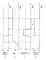
次に、ロックアップ禁止制御について、図7のタイミングチャートに基づいて説明する。図7(a)はロックアップクラッチ27の状態、すなわち連結状態(ON)であるか非連結状態(OFF)であるかを示している。図7(b)は車速の変化を示している。図7(c)は、ブーム操作部材83aの上げ操作量を示している。図7(d)は、ロックアップ禁止フラグを示している。また、トランスミッション26の速度段は第2速に固定されているものとする。
時点t0では車速は0であり、その後、車速が増大する。このとき、作業車両1の動力伝達状態は、第2速トルコン走行である。時点t1で車速が切換速度Vthに達すると、ロックアップクラッチ27が非連結状態から連結状態へと切り換えられる。次に、時点t2で、ブーム操作部材83aの上げ操作量が操作閾値Athに達すると、上述した負荷増大条件が満たされる。すると、ロックアップ禁止制御により、ロックアップ禁止フラグがONに設定される。これにより、ロックアップクラッチ27が連結状態から非連結状態に切り換えられる。次に、時点t3において、ブーム操作部材83aの上げ操作量が操作閾値Ath以下になると、負荷増大条件が満たされなくなる。しかし、この時点では、ロックアップ禁止フラグがONに維持され、ロックアップクラッチ27は連結状態には切り換えられない。その後、時点t3から時間dTが経過した時点t4において、ロックアップ禁止フラグがOFFに設定され、ロックアップ禁止が解除される。これにより、ロックアップクラッチ27が非連結状態から連結状態に切り換えられる。
次に、作業車両1がいわゆるVシェープ作業を行っているときのロックアップ禁止制御の処理の一例を説明する。Vシェープ作業とは、図8に示すように、作業車両1が、土砂などの荷物100を少しずつ作業機3によって持ち上げ、ダンプトラックなどの積み込み位置200に積み込む作業である。Vシェープ作業が行われるときは、比較的近距離での移動が繰り返されるので、変速操作部材85aは第2速位置に設定される。
まず、作業車両1は、荷物100に向かって移動する。このとき作業局面は「空荷前進」である。次に、作業車両1が荷物100に突っ込んでバケット7によって荷物100を持ち上げる。このとき作業局面は「掘削」である。次に、オペレータは、FR操作部材86aを前進位置から後進位置に切り換える。そして、作業車両1は、バケット7に荷物100を載せた状態で後退する。このとき、作業局面は「積荷後進」である。次に、オペレータはFR操作部材86aを後進位置から前進位置に切り換える。そして、作業車両1がバケット7に荷物100を載せた状態で、積み込み位置200に向かって前進する。このとき、作業局面は、「積荷前進」である。次に、作業車両1が積み込み位置200の近くに位置している状態で、バケット7上の荷物100を積み込み位置200に降ろす。上述した作業局面の判別には含まれていないが、このときの作業局面を「排土」と呼ぶ。次に、オペレータはFR操作部材86aを前進位置から後進位置に切り換え、作業車両1は、後進して積み込み位置200から離れる。このとき、作業局面は「空荷後進」である。次に、オペレータはFR操作部材86aを後進位置から前進位置に切り換え、再び荷物100に向かって前進する。
このVシェープ作業時のロックアップクラッチ27の切換を図9のタイミングチャートに示す。図9(a)はロックアップクラッチ27の状態を示している。図9(b)は、車速の変化を示している。図9(c)は、ブーム操作部材83aの上げ操作量を示している。図9(d)は、ロックアップ禁止フラグを示している。空荷前進時(時点T0-T2)には、作業車両1は荷物100に向かって前進する。このため、ブーム6の操作は行われず、車速が徐々に増大する。このとき、車速が切換速度Vthに達するまでは、ロックアップクラッチ27は非連結状態である(時点T0-T1)。また、上述した負荷増大条件は満たされていないので、ロックアップ禁止フラグはOFFであり、ロックアップの禁止は解除されている。従って、車速が切換速度Vthを越えると、ロックアップクラッチ27が連結状態に切り換えられる(時点T1-T2)。
掘削時(時点T2-T3)には、作業車両1が荷物100に突っ込んでバケット7によって荷物100を持ち上げる。このとき、上述した負荷増大条件が満たされる。このため、ロックアップ禁止フラグがONに設定され、ロックアップが禁止される。従って、車速が切換速度Vthを越えていても、ロックアップクラッチ27は非連結状態に切り換えられる。また、車速の変化に関わらず、ロックアップクラッチ27は非連結状態に維持される。
積荷後進時(時点T3-T6)には、作業車両1は、バケット7に荷物100を載せた状態で後退する。このため、ブーム6は低い位置に維持されたまま、車速が徐々に増大する。このとき、車速が切換速度Vthに達するまでは、ロックアップクラッチ27は非連結状態である(時点T3-T5)。なお、負荷増大条件が満たされなくなった時点T3から時間dTが経過した時点T4以降は、ロックアップ禁止フラグはOFFに設定されており、ロックアップの禁止は解除されている。従って、車速が切換速度Vthを越えると、ロックアップクラッチ27が連結状態に切り換えられる(時点T5-T6)。
積荷前進時(T6-T8)には、作業車両1がバケット7に荷物100を載せた状態で、積み込み位置200に向かって前進する。このとき、オペレータは、次の排土作業に備えて、ブーム操作部材83aを操作してバケット7を上昇させながら作業車両1を前進させる。ブーム操作部材83aの上げ操作量が操作量閾値Athを越えると(時点T7)、上述した負荷増大条件が満たされるため、ロックアップ禁止フラグがONに設定され、ロックアップが禁止される。従って、車速が切換速度Vthを越えても、ロックアップクラッチ27は非連結状態に維持される(時点T7-T8)。
排土時(T8-T9)には、作業車両1がゆっくりと前進しながら、オペレータがバケット操作部材84aを操作して、バケット7上の荷物100を積み込み位置200に降ろす。このときも、上述した負荷増大条件が満たされていると、ロックアップ禁止フラグはONであり、ロックアップが禁止される。また、車速が切換速度Vthより低いと、負荷増大条件が満たされていても、ロックアップクラッチ27は非連結状態に維持される。
空荷後進時(T9-T13)には、作業車両1は、ブーム6を下げながら後進して積み込み位置200から離れる。このとき、ブーム操作部材83aの上げ操作量が操作量閾値Ath以下となると(時点T10)、上述した負荷増大条件が満たされなくなる。そして、時点T10から時間dTが経過すると、ロックアップ禁止フラグがOFFに設定され、ロックアップの禁止が解除される(時点T11)。その後、ブーム6は低い位置に維持されたまま、車速が徐々に増大する。このとき、車速が切換速度Vthに達するまでは、ロックアップクラッチ27は非連結状態である(時点T11-T12)。また、上述した負荷増大条件は満たされていないので、ロックアップの禁止は解除されている。従って、車速が切換速度Vthを越えると、ロックアップクラッチ27が連結状態に切り換えられる(時点T12-T13)。
以上のように、本発明に係る作業車両では、ロックアップクラッチ27が非連結状態である場合に負荷増大条件が満たされているときは、ロックアップクラッチ27の連結状態への切換を禁止してロックアップクラッチ27を非連結状態に維持する。このため、作業機3に大きな負荷がかかる作業局面において、ロックアップクラッチ27が連結状態に切り換えられることが禁止される。また、ロックアップクラッチ27が連結状態である場合に負荷増大条件が満たされたときは、ロックアップクラッチ27が連結状態から非連結状態に切り換えられる。このため、作業機3に大きな負荷がかかる作業局面において、ロックアップクラッチ27が連結状態から非連結状態に切り換えられる。これにより、作業機3による作業性が低下することを抑えることができる。また、作業機3に大きな負荷がかからない作業局面においては、ロックアップ走行が活用されることにより、燃費を向上させることができる。
負荷増大条件の1つは、作業機3の作業局面が掘削であることである。また、負荷増大条件のもう1つは、ブーム操作部材83aの上げ操作量が所定の操作量閾値より大きく、且つ、トランスミッション26の実際の速度段が第2速であることである。これらの負荷増大条件の少なくとも一方が満たされたときに、ロックアップが禁止される。或いは、ロックアップクラッチ27が連結状態から非連結状態に切り換えられる。これらの負荷増大条件は、作業車両が、作業機3にかかる負荷が増大することが予想される状態であることを示している。このため、作業機3にかかる負荷が増大する事前に、ロックアップを禁止することができる。或いは、作業機3にかかる負荷が増大する事前に、ロックアップクラッチ27が連結状態から非連結状態に切り換えられる。これにより、作業機3にかかる負荷が増大したときに、作業機3による作業性が低下することを抑えることができる。
ロックアップの禁止の解除は、負荷増大条件が満たされなくなった時点で直ちに実行されるのではなく、所定時間dTが経過した後に実行される。このため、例えば、ブーム6の上げ下げが短時間に繰り返されたときに、ロックアップクラッチ27の連結状態、非連結状態の切換が繰り返されることを抑えることができる。従って、所定時間dtは、ロックアップクラッチ27の切換が頻繁に繰り返されることを抑えることができる程度の時間が設定されればよい。例えば、数秒程度の時間であればよい。
以上、本発明の一実施形態について説明したが、本発明は上記実施形態に限定されるものではなく、発明の要旨を逸脱しない範囲で種々の変更が可能である。
負荷増大条件は、上述した条件に限られず、作業機3への負荷の増大につながるものであれば他の条件が用いられてもよい。例えば、負荷増大条件に、車速が所定の速度閾値以下であることが含まれてもよい。具体的には、上述した負荷増大条件のうち、トランスミッション26の速度段が第2速であるという条件に代えて、車速が所定の速度閾値以下であることが判定されてもよい。所定の速度閾値は、作業車両1が高速で走行しており、作業機3よりも走行装置22の駆動を重視していると想定される値が設定される。なお、この所定の速度閾値は、ロックアップクラッチ27の切換速度より大きい。
また、負荷増大条件の1つは、トランスミッション26の速度段が、作業に適した低速の速度段であればよい。作業に適した低速の速度段は、上記の実施形態のように第2速であることが好ましい。ただし、5速トランスミッションが用いられる場合などギア比の設定によっては、作業に適した低速の速度段が第3速であってもよい。
また、上記の負荷増大条件に加えて、或いは、上記の負荷増大条件に代えて、以下に示す条件が用いられてもよい。これらの条件も、作業車両が作業機3への負荷の増大につながる状態である、或いは、作業機3への負荷の増大につながる操作が行われたことを示している。
(1)ブーム角が所定のブーム角度閾値より大きい。すなわち、バケットの高さが所定の高さ閾値より高い。
(2)作業局面が積荷である。
(3)バケット角が所定のバケット角度閾値より大きい。
(4)バケット操作部材84aの上げ操作量が所定の操作閾値より大きい。
(5)最高速度段が作業に適した低速の速度段である。
なお、上記(5)の作業に適した低速の速度段は、第2速が好ましい。また、作業に適した低速の速度段は、トランスミッション26の速度段数やギア比の設定によっては第3速であってもよい。さらに、作業に適した低速の速度段は、第2速以下(第2速及び第1速)という条件であってもよい。
(1)ブーム角が所定のブーム角度閾値より大きい。すなわち、バケットの高さが所定の高さ閾値より高い。
(2)作業局面が積荷である。
(3)バケット角が所定のバケット角度閾値より大きい。
(4)バケット操作部材84aの上げ操作量が所定の操作閾値より大きい。
(5)最高速度段が作業に適した低速の速度段である。
なお、上記(5)の作業に適した低速の速度段は、第2速が好ましい。また、作業に適した低速の速度段は、トランスミッション26の速度段数やギア比の設定によっては第3速であってもよい。さらに、作業に適した低速の速度段は、第2速以下(第2速及び第1速)という条件であってもよい。
また、作業機ポンプ13又はステアリングポンプ12の作動状況(例えば、ポンプ油圧、斜板角、流量、シリンダ速度)に基づいて負荷増大条件が判断されてもよい。なお、ブーム操作部材83a及びバケット操作部材84aなどの作業機操作部材の操作量については、上げ操作量に限らず、下げ操作量が負荷増大条件の判定に用いられてもよい。
上記の実施形態に係る作業車両では、第1制御部10aと第2制御部10bとが別に設けられているが、一体に設けられてもよい。例えば、1つのコンピュータによって第1制御部10aと第2制御部10bとの機能が実現されてもよい。逆に、第1制御部10a又は第2制御部10bの機能が複数のコンピュータによって分担されてもよい。
上記の各種の操作部材は、例示したようにペダル或いはレバーなどの部材に限られない。他にもダイヤルやスイッチなどが用いられてもよい。
ロックアップが禁止されていないときのロックアップクラッチ27の切換は、車速に限らず、他のパラメータに基づいて判定されてもよい。
作業機3の構成は、バケット7とブーム6とに限られず、他の部材であってもよい。また、バケット7に代えて他の作業アタッチメントがブーム6に取り付けられてもよい。
トランスミッション26の速度段は第1速から第4速に限られない。変速可能な速度段がより多くても又はより少なくてもよい。また、第2制御部10bによるトランスミッション26の変速パターンは上述したものに限られない。例えば、速度の増大に応じて第1速から順に変速が行われてもよい。
本発明によれば、作業性の低下を抑えると共に、燃費を向上させることができる作業車両及び作業車両の制御方法を提供することができる。
1 作業車両
3 作業機
6 ブーム
7 バケット(作業アタッチメント)
10 制御部
13 作業機ポンプ(油圧ポンプ)
21 エンジン
22 走行装置
23 トルクコンバータ装置
26 トランスミッション
27 ロックアップクラッチ
28 トルクコンバータ
83a ブーム操作部材(作業機操作部材)
83b ブーム操作検出装置(作業機操作検出部)
84a バケット操作部材(作業機操作部材)
84b バケット操作検出装置(作業機操作検出部)
92 T/M出力回転数センサ(車速検出部)
3 作業機
6 ブーム
7 バケット(作業アタッチメント)
10 制御部
13 作業機ポンプ(油圧ポンプ)
21 エンジン
22 走行装置
23 トルクコンバータ装置
26 トランスミッション
27 ロックアップクラッチ
28 トルクコンバータ
83a ブーム操作部材(作業機操作部材)
83b ブーム操作検出装置(作業機操作検出部)
84a バケット操作部材(作業機操作部材)
84b バケット操作検出装置(作業機操作検出部)
92 T/M出力回転数センサ(車速検出部)
Claims (10)
- エンジンと、
前記エンジンからの駆動力により駆動されて車両を走行させる走行装置と、
前記エンジンからの駆動力により駆動されて作動油を吐出する油圧ポンプと、
前記油圧ポンプからの作動油により駆動される作業機と、
トルクコンバータとロックアップクラッチとを有し、前記エンジンからの駆動力を前記走行装置に伝達するトルクコンバータ装置と、
車両の走行状態に応じて前記ロックアップクラッチを連結状態と非連結状態とに切り換える制御部と、
を備え、
前記制御部は、
前記作業機への負荷の増大につながる負荷増大条件が満たされているか否かを判定し、
前記負荷増大条件が満たされているときは前記ロックアップクラッチが非連結状態であるように前記ロックアップクラッチを制御する、
作業車両。 - 前記制御部は、前記ロックアップクラッチが非連結状態である場合に前記負荷増大条件が満たされているときは、前記ロックアップクラッチの連結状態への切換を禁止して前記ロックアップクラッチを非連結状態に維持する、
請求項1に記載の作業車両。 - 前記制御部は、前記ロックアップクラッチが連結状態である場合に前記負荷増大条件が満たされたときは、前記ロックアップクラッチを連結状態から非連結状態に切り換える、
請求項1に記載の作業車両。 - 前記作業機を操作するための作業機操作部材と、
前記作業機操作部材の操作量を検出する作業機操作検出部と、
をさらに備え、
前記負荷増大条件は、前記作業機操作部材の操作量が所定の操作量閾値より大きいことを含む、
請求項1に記載の作業車両。 - 前記作業機は、前記作業機操作部材の操作に応じて上下に揺動するブームと、前記ブームの先端に取り付けられる作業アタッチメントと、を有する、
請求項4に記載の作業車両。 - 前記負荷増大条件は、前記作業車両の作業局面が掘削であることを含む、
請求項1に記載の作業車両。 - 前記走行装置は、第1速から第3速以上の速度段に変速可能なトランスミッションを有し、
前記負荷増大条件は、前記トランスミッションの速度段が第2速であることをさらに含む、
請求項4に記載の作業車両。 - 車速を検出する車速検出部をさらに備え、
前記負荷増大条件は、前記車速が所定の速度閾値以下であることをさらに含む、
請求項4に記載の作業車両。 - 前記制御部は、前記負荷増大条件が満たされなくなった時点から所定時間経過したときに、前記ロックアップクラッチの連結状態への切換の禁止を解除する、
請求項2に記載の作業車両。 - エンジンと、前記エンジンからの駆動力により駆動されて車両を走行させる走行装置と、前記エンジンからの駆動力により駆動されて作動油を吐出する油圧ポンプと、前記油圧ポンプからの作動油により駆動される作業機と、トルクコンバータとロックアップクラッチとを有し前記エンジンからの駆動力を前記走行装置に伝達するトルクコンバータ装置と、を備える作業車両の制御方法であって、
車両の走行状態に応じて前記ロックアップクラッチを連結状態と非連結状態とに切り換えるステップと、
前記作業機への負荷の増大につながる負荷増大条件が満たされているか否かを判定するステップと、
前記負荷増大条件が満たされているときは前記ロックアップクラッチが非連結状態であるように前記ロックアップクラッチを制御するステップと、
を備える作業車両の制御方法。
Priority Applications (3)
| Application Number | Priority Date | Filing Date | Title |
|---|---|---|---|
| CN201180009523.7A CN102753867B (zh) | 2010-02-16 | 2011-01-31 | 作业车辆及作业车辆的控制方法 |
| EP11744498.4A EP2538121B1 (en) | 2010-02-16 | 2011-01-31 | Work vehicle and work vehicle control method |
| US13/577,434 US8977444B2 (en) | 2010-02-16 | 2011-01-31 | Work vehicle and work vehicle control method |
Applications Claiming Priority (2)
| Application Number | Priority Date | Filing Date | Title |
|---|---|---|---|
| JP2010031463A JP5237313B2 (ja) | 2010-02-16 | 2010-02-16 | 作業車両及び作業車両の制御方法 |
| JP2010-031463 | 2010-02-16 |
Publications (1)
| Publication Number | Publication Date |
|---|---|
| WO2011102209A1 true WO2011102209A1 (ja) | 2011-08-25 |
Family
ID=44482804
Family Applications (1)
| Application Number | Title | Priority Date | Filing Date |
|---|---|---|---|
| PCT/JP2011/051882 WO2011102209A1 (ja) | 2010-02-16 | 2011-01-31 | 作業車両及び作業車両の制御方法 |
Country Status (5)
| Country | Link |
|---|---|
| US (1) | US8977444B2 (ja) |
| EP (1) | EP2538121B1 (ja) |
| JP (1) | JP5237313B2 (ja) |
| CN (1) | CN102753867B (ja) |
| WO (1) | WO2011102209A1 (ja) |
Cited By (1)
| Publication number | Priority date | Publication date | Assignee | Title |
|---|---|---|---|---|
| CN103582587A (zh) * | 2012-03-29 | 2014-02-12 | 株式会社小松制作所 | 作业车辆及作业车辆的控制方法 |
Families Citing this family (13)
| Publication number | Priority date | Publication date | Assignee | Title |
|---|---|---|---|---|
| US9102372B2 (en) * | 2012-07-24 | 2015-08-11 | Caterpillar Inc. | Track drive system and method |
| US9097344B2 (en) * | 2012-09-28 | 2015-08-04 | Caterpillar Inc. | Automatic shift control system for a powertrain and method |
| JP5592026B1 (ja) * | 2013-02-28 | 2014-09-17 | 株式会社小松製作所 | 作業車両 |
| EP2927072B1 (en) * | 2013-10-18 | 2018-12-05 | Komatsu Ltd. | Work vehicle and method for controlling work vehicle |
| US9551131B2 (en) | 2014-12-10 | 2017-01-24 | Caterpillar Inc. | Power system having clutch-based fuel control modes |
| US9619948B2 (en) | 2015-08-06 | 2017-04-11 | Caterpillar Inc. | System and method for monitoring an earth-moving operation of a machine |
| WO2016111384A1 (ja) * | 2016-02-29 | 2016-07-14 | 株式会社小松製作所 | 作業機械の制御装置、作業機械及び作業機械の制御方法 |
| US10513263B2 (en) | 2017-11-13 | 2019-12-24 | Caterpillar Inc. | Retarding system and lock-up clutch engagement control |
| JP6749885B2 (ja) * | 2017-12-28 | 2020-09-02 | 日立建機株式会社 | ホイールローダ |
| JP2019173784A (ja) * | 2018-03-27 | 2019-10-10 | 株式会社Kcm | 作業車両 |
| US10745886B2 (en) | 2018-06-08 | 2020-08-18 | Deere & Company | Torque converter control based on work vehicle parameters |
| US11384508B2 (en) * | 2019-02-12 | 2022-07-12 | Caterpillar Inc. | Automated machine impeller clutch |
| JP7141974B2 (ja) * | 2019-03-25 | 2022-09-26 | 日立建機株式会社 | ホイールローダ |
Citations (4)
| Publication number | Priority date | Publication date | Assignee | Title |
|---|---|---|---|---|
| JP2002174332A (ja) * | 2000-09-18 | 2002-06-21 | Fuji Heavy Ind Ltd | 作業用車両 |
| WO2009054256A1 (ja) * | 2007-10-22 | 2009-04-30 | Komatsu Ltd. | 作業車両の変速制御装置および方法 |
| JP2009103258A (ja) | 2007-10-25 | 2009-05-14 | Komatsu Ltd | 作業車両および作業車両の制御方法 |
| JP2009103266A (ja) * | 2007-10-25 | 2009-05-14 | Tcm Corp | 作業車両の変速制御装置 |
Family Cites Families (13)
| Publication number | Priority date | Publication date | Assignee | Title |
|---|---|---|---|---|
| JP2759019B2 (ja) * | 1992-05-27 | 1998-05-28 | 株式会社クボタ | トラクタのロックアップ付トルコンの制御装置 |
| JP2002071010A (ja) * | 2000-08-25 | 2002-03-08 | Toyota Motor Corp | 流体伝動装置の制御装置 |
| JP2004225879A (ja) * | 2003-01-27 | 2004-08-12 | Nissan Motor Co Ltd | 車両のロックアップ制御装置 |
| DE602004013201T2 (de) * | 2004-07-27 | 2009-07-09 | Volvo Construction Equipment Ab | Verfahren und vorrichtung zur steuerung der bewegungen eines arbeitsfahrzeugs |
| EP1801294B1 (en) * | 2004-07-27 | 2012-01-04 | Volvo Construction Equipment AB | A method and a device for controlling movement of a work vehicle |
| AU2004222734B1 (en) * | 2004-10-20 | 2006-01-19 | Leica Geosystems Ag | Method and apparatus for monitoring a load condition of a dragline |
| CN101287876B (zh) * | 2005-10-14 | 2011-11-02 | 株式会社小松制作所 | 作业车辆的发动机及液压泵的控制装置及方法 |
| JP4846359B2 (ja) * | 2005-12-22 | 2011-12-28 | 株式会社小松製作所 | 作業車両の制御装置 |
| US7673714B2 (en) * | 2007-02-21 | 2010-03-09 | Ford Global Technologies, Llc | System and method of torque converter lockup state adjustment using an electric energy conversion device |
| JP5162785B2 (ja) * | 2007-09-28 | 2013-03-13 | 株式会社小松製作所 | 作業車両の変速制御装置 |
| US8287433B2 (en) * | 2008-01-10 | 2012-10-16 | Komatsu Ltd. | Work vehicle |
| DE102008043106A1 (de) * | 2008-10-23 | 2010-04-29 | Zf Friedrichshafen Ag | Verfahren zum Betreiben der Wandlerüberbrückungskupplung in einem Lastschaltgetriebe einer Arbeitsmaschine umfassend zumindest eine hydraulisch betätigbare Hubeinrichtung |
| EP2489905B1 (en) * | 2010-02-10 | 2017-09-13 | Komatsu Ltd. | Working vehicle and control method for working vehicle |
-
2010
- 2010-02-16 JP JP2010031463A patent/JP5237313B2/ja active Active
-
2011
- 2011-01-31 CN CN201180009523.7A patent/CN102753867B/zh active Active
- 2011-01-31 WO PCT/JP2011/051882 patent/WO2011102209A1/ja active Application Filing
- 2011-01-31 EP EP11744498.4A patent/EP2538121B1/en active Active
- 2011-01-31 US US13/577,434 patent/US8977444B2/en active Active
Patent Citations (4)
| Publication number | Priority date | Publication date | Assignee | Title |
|---|---|---|---|---|
| JP2002174332A (ja) * | 2000-09-18 | 2002-06-21 | Fuji Heavy Ind Ltd | 作業用車両 |
| WO2009054256A1 (ja) * | 2007-10-22 | 2009-04-30 | Komatsu Ltd. | 作業車両の変速制御装置および方法 |
| JP2009103258A (ja) | 2007-10-25 | 2009-05-14 | Komatsu Ltd | 作業車両および作業車両の制御方法 |
| JP2009103266A (ja) * | 2007-10-25 | 2009-05-14 | Tcm Corp | 作業車両の変速制御装置 |
Cited By (2)
| Publication number | Priority date | Publication date | Assignee | Title |
|---|---|---|---|---|
| CN103582587A (zh) * | 2012-03-29 | 2014-02-12 | 株式会社小松制作所 | 作业车辆及作业车辆的控制方法 |
| CN103582587B (zh) * | 2012-03-29 | 2014-11-05 | 株式会社小松制作所 | 作业车辆及作业车辆的控制方法 |
Also Published As
| Publication number | Publication date |
|---|---|
| CN102753867A (zh) | 2012-10-24 |
| JP2011169347A (ja) | 2011-09-01 |
| EP2538121A1 (en) | 2012-12-26 |
| US8977444B2 (en) | 2015-03-10 |
| EP2538121A4 (en) | 2015-09-09 |
| CN102753867B (zh) | 2014-12-10 |
| EP2538121B1 (en) | 2019-09-18 |
| JP5237313B2 (ja) | 2013-07-17 |
| US20120310493A1 (en) | 2012-12-06 |
Similar Documents
| Publication | Publication Date | Title |
|---|---|---|
| JP5237313B2 (ja) | 作業車両及び作業車両の制御方法 | |
| JP5205408B2 (ja) | 作業車両及び作業車両の制御方法 | |
| JP5161380B1 (ja) | 作業車両及び作業車両の制御方法 | |
| EP2543776B1 (en) | Work vehicle and work vehicle control method | |
| JP5048068B2 (ja) | 作業車両及び作業車両の作動油量制御方法 | |
| JP4482522B2 (ja) | エンジン出力制御装置 | |
| JP5228132B1 (ja) | ホイールローダ | |
| JP5181063B2 (ja) | 作業車両及び作業車両の制御方法 | |
| EP2267230B1 (en) | Working vehicle, control device for working vehicle, and operating-oil amount control method for working vehicle | |
| JP5808686B2 (ja) | 作業車両のエンジン制御装置 | |
| JP5204837B2 (ja) | 作業車両、作業車両の制御装置、及び作業車両の制御方法 | |
| EP2700799B1 (en) | Wheel loader | |
| US11505921B2 (en) | Wheel loader | |
| JP2013204631A (ja) | 作業車両及び作業車両の制御方法 | |
| EP2905385B1 (en) | Method for controlling industrial vehicle, device for controlling industrial vehicle, and industrial vehicle | |
| CN111133154B (zh) | 轮式装载机 | |
| EP2933384B1 (en) | Method and device for controlling working vehicle, and working vehicle | |
| WO2010052831A1 (ja) | 作業車両 | |
| KR102452805B1 (ko) | 휠 로더의 제어 방법 및 시스템 |
Legal Events
| Date | Code | Title | Description |
|---|---|---|---|
| WWE | Wipo information: entry into national phase |
Ref document number: 201180009523.7 Country of ref document: CN |
|
| 121 | Ep: the epo has been informed by wipo that ep was designated in this application |
Ref document number: 11744498 Country of ref document: EP Kind code of ref document: A1 |
|
| WWE | Wipo information: entry into national phase |
Ref document number: 13577434 Country of ref document: US |
|
| NENP | Non-entry into the national phase |
Ref country code: DE |
|
| WWE | Wipo information: entry into national phase |
Ref document number: 2011744498 Country of ref document: EP |