EP2933384B1 - Method and device for controlling working vehicle, and working vehicle - Google Patents
Method and device for controlling working vehicle, and working vehicle Download PDFInfo
- Publication number
- EP2933384B1 EP2933384B1 EP14759087.1A EP14759087A EP2933384B1 EP 2933384 B1 EP2933384 B1 EP 2933384B1 EP 14759087 A EP14759087 A EP 14759087A EP 2933384 B1 EP2933384 B1 EP 2933384B1
- Authority
- EP
- European Patent Office
- Prior art keywords
- bucket
- boom
- dump
- operation amount
- cylinder
- Prior art date
- Legal status (The legal status is an assumption and is not a legal conclusion. Google has not performed a legal analysis and makes no representation as to the accuracy of the status listed.)
- Active
Links
Images


Classifications
-
- E—FIXED CONSTRUCTIONS
- E02—HYDRAULIC ENGINEERING; FOUNDATIONS; SOIL SHIFTING
- E02F—DREDGING; SOIL-SHIFTING
- E02F3/00—Dredgers; Soil-shifting machines
- E02F3/04—Dredgers; Soil-shifting machines mechanically-driven
- E02F3/28—Dredgers; Soil-shifting machines mechanically-driven with digging tools mounted on a dipper- or bucket-arm, i.e. there is either one arm or a pair of arms, e.g. dippers, buckets
- E02F3/36—Component parts
- E02F3/42—Drives for dippers, buckets, dipper-arms or bucket-arms
- E02F3/43—Control of dipper or bucket position; Control of sequence of drive operations
- E02F3/431—Control of dipper or bucket position; Control of sequence of drive operations for bucket-arms, front-end loaders, dumpers or the like
- E02F3/434—Control of dipper or bucket position; Control of sequence of drive operations for bucket-arms, front-end loaders, dumpers or the like providing automatic sequences of movements, e.g. automatic dumping or loading, automatic return-to-dig
-
- E—FIXED CONSTRUCTIONS
- E02—HYDRAULIC ENGINEERING; FOUNDATIONS; SOIL SHIFTING
- E02F—DREDGING; SOIL-SHIFTING
- E02F3/00—Dredgers; Soil-shifting machines
- E02F3/04—Dredgers; Soil-shifting machines mechanically-driven
- E02F3/28—Dredgers; Soil-shifting machines mechanically-driven with digging tools mounted on a dipper- or bucket-arm, i.e. there is either one arm or a pair of arms, e.g. dippers, buckets
- E02F3/36—Component parts
- E02F3/42—Drives for dippers, buckets, dipper-arms or bucket-arms
- E02F3/43—Control of dipper or bucket position; Control of sequence of drive operations
- E02F3/431—Control of dipper or bucket position; Control of sequence of drive operations for bucket-arms, front-end loaders, dumpers or the like
- E02F3/432—Control of dipper or bucket position; Control of sequence of drive operations for bucket-arms, front-end loaders, dumpers or the like for keeping the bucket in a predetermined position or attitude
-
- E—FIXED CONSTRUCTIONS
- E02—HYDRAULIC ENGINEERING; FOUNDATIONS; SOIL SHIFTING
- E02F—DREDGING; SOIL-SHIFTING
- E02F9/00—Component parts of dredgers or soil-shifting machines, not restricted to one of the kinds covered by groups E02F3/00 - E02F7/00
- E02F9/20—Drives; Control devices
- E02F9/2025—Particular purposes of control systems not otherwise provided for
- E02F9/2029—Controlling the position of implements in function of its load, e.g. modifying the attitude of implements in accordance to vehicle speed
-
- E—FIXED CONSTRUCTIONS
- E02—HYDRAULIC ENGINEERING; FOUNDATIONS; SOIL SHIFTING
- E02F—DREDGING; SOIL-SHIFTING
- E02F9/00—Component parts of dredgers or soil-shifting machines, not restricted to one of the kinds covered by groups E02F3/00 - E02F7/00
- E02F9/20—Drives; Control devices
- E02F9/22—Hydraulic or pneumatic drives
- E02F9/2278—Hydraulic circuits
- E02F9/2296—Systems with a variable displacement pump
-
- E—FIXED CONSTRUCTIONS
- E02—HYDRAULIC ENGINEERING; FOUNDATIONS; SOIL SHIFTING
- E02F—DREDGING; SOIL-SHIFTING
- E02F3/00—Dredgers; Soil-shifting machines
- E02F3/04—Dredgers; Soil-shifting machines mechanically-driven
- E02F3/28—Dredgers; Soil-shifting machines mechanically-driven with digging tools mounted on a dipper- or bucket-arm, i.e. there is either one arm or a pair of arms, e.g. dippers, buckets
- E02F3/34—Dredgers; Soil-shifting machines mechanically-driven with digging tools mounted on a dipper- or bucket-arm, i.e. there is either one arm or a pair of arms, e.g. dippers, buckets with bucket-arms, i.e. a pair of arms, e.g. manufacturing processes, form, geometry, material of bucket-arms directly pivoted on the frames of tractors or self-propelled machines
- E02F3/3417—Buckets emptying by tilting
-
- E—FIXED CONSTRUCTIONS
- E02—HYDRAULIC ENGINEERING; FOUNDATIONS; SOIL SHIFTING
- E02F—DREDGING; SOIL-SHIFTING
- E02F3/00—Dredgers; Soil-shifting machines
- E02F3/04—Dredgers; Soil-shifting machines mechanically-driven
- E02F3/28—Dredgers; Soil-shifting machines mechanically-driven with digging tools mounted on a dipper- or bucket-arm, i.e. there is either one arm or a pair of arms, e.g. dippers, buckets
- E02F3/34—Dredgers; Soil-shifting machines mechanically-driven with digging tools mounted on a dipper- or bucket-arm, i.e. there is either one arm or a pair of arms, e.g. dippers, buckets with bucket-arms, i.e. a pair of arms, e.g. manufacturing processes, form, geometry, material of bucket-arms directly pivoted on the frames of tractors or self-propelled machines
- E02F3/342—Buckets emptying overhead
Definitions
- a wheel loader is a vehicle having a bucket for performing excavation work, which works by traveling with tires.
- WO 2010/110386 A discloses causing a bucket to perform tilting automatically during rising of a boom.
- a bucket If a bucket is caused to perform tilting automatically during rising of the boom, the bucket performs tilting even when an operator does not perform an operation to tilt the bucket, which may give the operator a sense of discomfort.
- An object of the present invention is to reduce a sense of discomfort given to the operator when the bucket is caused to tilt automatically during rising of the boom.
- the present invention is able to reduce a sense of discomfort given to the operator when the bucket is caused to tilt automatically during rising of the boom.
- the boom cylinder 9, working as a boom driving device, is disposed between the vehicle body 2 and the boom 3.
- the boom 3 turns about the supporting part on the vehicle body 2 side according to expansion and contraction of the boom cylinder 9.
- the boom driving device which allows the boom 3 to turn is not limited to the boom cylinder 9.
- the boom driving device may be an electric motor provided to the root of the boom 3.
- the boom driving device is an actuator which allows the boom 3 to turn.
- the work machine hydraulic pump 12 is driven by an engine (EG) 60 as a power generator mounted on the wheel loader 1.
- the engine 60 is an internal combustion engine, and in the present embodiment, it is a diesel engine.
- the type of the engine 60 is not limited to a diesel engine.
- the power of the engine 60 is input to a PTO (Power Take Off) 61, and then output to the work machine hydraulic pump 12 and to a clutch 62 as a power transmission mechanism.
- PTO Power Take Off
- the work machine hydraulic pump 12 is driven by the engine 60 via the PTO 61, and discharges hydraulic oil.
- the input side of the clutch 62 is connected with the engine 60, and the output side of the clutch 62 is connected with a torque converter (TC) 63.
- the output side of the torque converter 63 is connected with a transmission (TM) 64.
- the transmission 64 transmits the power of the engine 60, transmitted from the PTO 61, to the front wheels 6F and the rear wheels 6R shown in FIG. 1 , and drives them.
- the wheel loader 1 and the vehicle body 2 travel with the front wheel 6F and the rear wheel 6R being driven by the output of the engine 60.
- the front wheels 6F and the rear wheels 6R work as drive wheels of the wheel loader 1.
- the discharge port from which the work machine hydraulic pump 12 discharges hydraulic oil, is connected with the discharge circuit 12C working as an oil passage through which the hydraulic oil passes.
- the discharge circuit 12C is connected with the boom operation valve 13 and the bucket operation valve 14. Both the boom operation valve 13 and the bucket operation valve 14 are hydraulic pilot type operation valves.
- the boom operation valve 13 and the bucket operation valve 14 are connected with the boom cylinder 9 and the bucket cylinder 10, respectively.
- the work machine hydraulic pump 12, the boom operation valve 13, the bucket operation valve 14, and the discharge circuit 12C constitute a tandem hydraulic circuit.
- the electromagnetic proportional control valve 20 includes a boom lowering electromagnetic proportional control valve 21, a boom raising electromagnetic proportional control valve 22, a bucket dump electromagnetic proportional control valve 23, and a bucket tilt electromagnetic proportional control valve 24.
- the boom lowering electromagnetic proportional control valve 21 and the boom raising electromagnetic proportional control valve 22 are connected with the respective pilot pressure receiving parts 13R and 13R of the boom operation valve 13.
- the bucket dump electromagnetic proportional control valve 23 and the bucket tilt electromagnetic proportional control valve 24 are connected with the respective pilot pressure receiving part 14R and 14R of the bucket operation valve 14.
- the boom lowering electromagnetic proportional control valve 21, the boom raising electromagnetic proportional control valve 22, the boom operation valve 13, and the boom cylinder 9 have a function as a boom driving part to turn (move up and down) the boom 3.
- the bucket dump electromagnetic proportional control valve 23, the bucket tilt electromagnetic proportional control valve 24, the bucket operation valve 14, and the bucket cylinder 10 have a function as a bucket driving part to turn the bucket (perform tilting or dumping).
- the processing unit 41 gives a command value for operating the boom cylinder 9 to the solenoid command part 23S of the bucket dump electromagnetic proportional control valve 23 or the solenoid command part 24S of the bucket tilt electromagnetic proportional control valve 24 to thereby extend or contract the bucket cylinder 10. With extension or contraction of the bucket cylinder 10, the bucket 4 performs tilting or dumping. In this way, the processing unit 41 controls operation of the work machine 5, that is, operation of the boom 3 and the bucket 4.
- the position of the bucket 4, when the bucket is in contact with the tilt stopper STPT, is called a tilt end.
- the dump stopper STPD is used to regulate the dumping of the bucket 4, the present invention is not limited to this.
- a stroke end of the bucket cylinder 10 may regulates the dumping of the bucket 4, instead of the dump stopper STPD.
- the bucket 4 is configured such that dumping stops at the stop position on the dump side.
- the stop position on the dump side may be the position of the dump stopper STPD or the position of the stroke end of the bucket cylinder 10, for example.
- the wheel loader 1 raises the boom 3 to thereby lift the bucket 4 which scooped dirt, quarried stones, or the like to an upper position UP, and load the dirt, crushed stores, or the like on a vessel of the dump truck, for example.
- the wheel loader 1 contracts the bucket cylinder 10 so as to allow the bucket 4 to perform dumping to thereby cause the claw 4C of the bucket 4 to face downward.
- the dirt, crushed stones, or the like, held by the bucket 4 is released from the bucket 4 to the vessel.
- Dumping is an operation that the claw 4C of the bucket 4 moves downward (operation to move in a direction shown by an arrow DP in FIG. 4 ).
- the automatic tilt is performed in a state where the bucket 4 is stopped, that is, in a state where the operator does not operate the bucket control lever 32.
- the automatic tilt is performed, as the bucket 4 is operated automatically, the operator may recognize that unintentional operation of the bucket 4 is caused and feel a sense of discomfort. As such, it is preferable that the operation of the bucket 4 in the automatic tilt should be kept to a requisite minimum.
- the length of the bucket cylinder 10 equals to the length when the bucket 4 comes in contact with the dump stopper STPD.
- the control device 40 illustrated in FIG. 2 makes the operation of the bucket 4 a requisite minimum by performing the automatic tilt by the work vehicle control method according to the present embodiment.
- the tilt command CC varies as a line "e" illustrated in FIG. 11 , in accordance with the change of the reach distance SCR. If the boom raising operation amount BVC in the automatic tilt table TBC is 50%, the tilt command CC varies as a line "f” illustrated in FIG. 11 , in accordance with the change of the reach distance SCR. If the boom raising operation amount BVC in the automatic tilt table TBC is 100%, the tilt command CC varies as a line "g" illustrated in FIG. 11 , in accordance with the change of the reach distance SCR.
- the tilt command CC is a command to cause the bucket 4 to perform tilting, and is a command to change the operation amount of the bucket cylinder 10. Specifically, the operating speed of the bucket cylinder 10 is changed by the tilt command CC. For example, if the tilt command CC is -10, the bucket cylinder 10 is extended at an operating speed corresponding to the tilt command CC.
- the tilt command CC is configured such that as the absolute value thereof is larger, the operation amount of the bucket cylinder 10 to cause the bucket 4 to perform tilting, that is, an operating speed in the present embodiment, is larger.
- the automatic tilt table TBC is configured such that as the absolute value of the reach distance SCR of the bucket cylinder 10 is smaller, that is, as the bucket 4 comes closer to the dump stopper STPD, the tilt command CC is larger. Further, the automatic tilt table TBC is configured such that the tilt command CC is given when the boom raising operation amount BVC is larger than 0%.
- the control device 40 illustrated in FIG. 2 changes the tilt command CC based on the boom raising operation amount BVC or the rising speed of the boom 3 to thereby change the operation amount of the bucket cylinder 10 for making the bucket 4 tilt, and cause the bucket 4 to perform tilting corresponding to the reach distance SCR of the bucket cylinder 10. With this configuration, a contact between the bucket 4 and the dump stopper STPD is prevented during rising of the boom 3.
- the automatic tilt table TBC is configured such that as the boom raising operation amount BVC is larger or the rising speed of the boom 3 is higher, the bucket cylinder 10 is caused to be operated from a position where the reach distance SCR is large so as to cause the bucket 4 to perform tilting.
- the boom raising operation amount BVC is large or the rising speed of the boom 3 is high, as the bucket 4 performs tilting automatically at earlier timing, a pressure contact between the bucket 4 and the dump stopper STPD can be prevented reliably.
- the control device 40 sets zero to the tilt command CC when the reach distance SCR is zero to thereby stop tilting of the bucket 4.
- the tilt command CC is zero when the reach distance SCR is zero.
- the boom raising operation amount BVC is 50% or 100%
- the tilt command CC is -10.
- the boom raising operation amount BVC is 50% or 100%, even if the reach distance SCR is zero, the bucket 4 performs tilting.
- the control device 40 when the boom raising operation amount BVC becomes 0% or the rising speed of the boom 3 becomes zero during rising of the boom 3, the control device 40 is able to stop the bucket 4 at a target position, that is, a position closer to a position where the bucket 4 comes in contact with the dump stopper STPD. Consequently, the control device 40 is able to keep the operation of the bucket 4 in the automatic tilt to be a requisite minimum. Thereby, it is possible to reduce a sense of discomfort given to the operator.
- the automatic tilt table TBC is configured such that if the boom raising operation amount BVC is larger than 0%, a value other than zero (-10 in the present embodiment) is set to the tilt command CC, to thereby reduce the possibility that intervention and non-intervention of automatic tilt are repeated. Consequently, a sense of discomfort given to the operator in automatic tilt can be further reduced.
- FIG. 12 is a flowchart illustrating exemplary control at the time of automatic tilting in the work vehicle control method according to the present embodiment.
- the control device 40 illustrated in FIG. 2 determines that the bucket 4 is neutral, that is, the bucket 4 is not operated. If the bucket control lever 32 illustrated in FIG. 2 is neutral, the bucket 4 is neutral. The control device 40 determines whether or not the bucket control lever 32 is in a neutral state from the detection value of the second potentiometer 33 illustrated in FIG. 2 .
- step S201 If the bucket 4 is neutral (step S201, Yes), the process proceeds to step S202, and the control device 40 determines the boom raising operation, that is, whether or not the boom 3 is being raised or stopped. The control device 40 determines that the boom 3 is being raised or stopped if the boom raising operation amount BVC is 0% or larger. If the boom 3 is being raised (step S202, Yes), at step S203, the control device 40 performs automatic tilting by using the automatic tilt table TBC. If the bucket 4 is not neutral (step S201, No) and the boom 3 is not being raised or stopped (step S202, No), the control device 40 goes back to the start and performs the process after step S101. If the boom 3 is not being raised or stopped, it means the boom 3 is being lowered.
Description
- The present invention relates to a work vehicle which performs excavation work.
- Work vehicles equipped with a work machine used to load dirt, crushed stones, or the like onto a dump truck or the like have been known. As such a work vehicle, there is a wheel loader. A wheel loader is a vehicle having a bucket for performing excavation work, which works by traveling with tires. For example,
WO 2010/110386 A discloses causing a bucket to perform tilting automatically during rising of a boom. -
EP 2 412 875 A1 - If a bucket is caused to perform tilting automatically during rising of the boom, the bucket performs tilting even when an operator does not perform an operation to tilt the bucket, which may give the operator a sense of discomfort.
- An object of the present invention is to reduce a sense of discomfort given to the operator when the bucket is caused to tilt automatically during rising of the boom. Solution to Problem
- According to the present invention, a work vehicle control method comprises, in controlling a work vehicle including a boom supported by a vehicle body and configured to turn; and a bucket supported by a side, away from the vehicle body, of the boom and configured to turn according to an operation of an actuator: obtaining an operation amount for raising the boom or a rising speed of the boom and an operable amount that the actuator is able to operate before the bucket reaches a stop position on a dump side, the operable amount being obtained based on a posture of the boom and a posture of the bucket; and causing the bucket to perform tilting by operating the actuator from a position where the operable amount reaches a threshold such that said threshold is increased depending on an increase of the operation amount for raising the boom or on an increase of the rising speed of the boom.
- According to the present invention, a work vehicle control device which controls a work vehicle including a boom supported by a vehicle body and configured to turn; and a bucket supported by a side, away from the vehicle body, of the boom, and configured to turn according to an operation of an actuator, wherein the work vehicle control device obtains an operation amount for raising the boom or a rising speed of the boom, and an operable amount that the actuator is able to operate before the bucket reaches a stop position on a dump side, the operable amount being obtained based on a posture of the boom and a posture of the bucket, and the work vehicle control device causes the bucket to perform tilting by operating the actuator from a position where the operable amount reaches a threshold such that said threshold is increased depending on an increase of the operation amount for raising the boom or on an increase of the rising speed of the boom.
- According to the present invention, a work vehicle comprises: a boom supported by a vehicle body and configured to turn; a bucket supported by a side, away from the vehicle body, of the boom, and configured to turn according to an operation of an actuator; and the work vehicle control device.
- It is preferable to cause the bucket to perform tilting according to the operable amount in the case where the boom is raised and a device for operating the bucket is in a neutral state.
- The present invention is able to reduce a sense of discomfort given to the operator when the bucket is caused to tilt automatically during rising of the boom.
-
-
FIG. 1 is a diagram illustrating a work vehicle according to the present embodiment. -
FIG. 2 is a diagram illustrating a control system for controlling operation of a work machine. -
FIG. 3 is a diagram illustrating a work machine. -
FIG. 4 is a diagram for explaining tilting and dumping of a bucket provided to a wheel loader. -
FIG. 5 is a drawing illustrating an example of a first table for control to be used for control at the time of dumping in a work vehicle control method according to the present embodiment. -
FIG. 6 is a drawing illustrating an example of a second table for control to be used for control at the time of dumping in the work vehicle control method according to the present embodiment. -
FIG. 7 is a drawing illustrating a relationship between a limit rate of a boom rising speed and a reach distance of a bucket cylinder. -
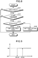
FIG. 8 is a flowchart illustrating an example of control at the time of dumping in the work vehicle control method according to the present embodiment. -
FIG. 9 is a drawing for explaining determination to start and stop control at the time of dumping. -
FIG. 10 is a drawing illustrating an example of an automatic tilt table to be used for control when a bucket is caused to perform tilting automatically in the work vehicle control method according to the present embodiment. -
FIG. 11 is a drawing illustrating a relationship between a tilt command and a reach distance of a bucket cylinder. -
FIG. 12 is a flowchart illustrating exemplary control at the time of automatic tilting in the work vehicle control method according to the present embodiment. Description of Embodiments - A mode for carrying out the present invention (embodiment) will be described in detail with reference to the drawings.
-
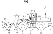
FIG. 1 is a diagram illustrating a work vehicle according to the present embodiment. In the present embodiment, as an example of a work vehicle, description will be given on awheel loader 1 which loads crushed stones, dirt generated when excavating crushed stones, rocks, or the like onto a dump truck or the like as a delivery vehicle. - The
wheel loader 1 includes avehicle body 2, awork machine 5 equipped with aboom 3 and abucket 4,front wheels 6F andrear wheels 6R, a driver'scabin 7, aboom cylinder 9 corresponding to an actuator, and abucket cylinder 10 corresponding to an actuator. On thevehicle body 2, thework machine 5, thefront wheels 6F and therear wheels 6R, and the driver'scabin 7 are mounted. In the driver'scabin 7, a driver's seat DS and a control lever CL are provided. A direction from the backrest DSB of the driver's seat DS to the control lever CL is called front, and a direction from the control lever CL to the backrest DSB is called back. Right and left of thewheel loader 1 is determined with reference to the front. - The
front wheels 6F and therear wheels 6R are grounded on a road surface R. The grounded side of thefront wheels 6F and therear wheels 6R is called downward, and a direction separating from the grounded side of thefront wheels 6F and therear wheels 6R is called upward. With rotation of thefront wheels 6F and therear wheels 6R, thewheel loader 1 travels. Steering of thewheel loader 1 is realized by bending thevehicle body 2 between thefront wheels 6F and therear wheels 6R. - The
work machine 5 is disposed on the front part of thevehicle body 2. Theboom 3 is supported on the front side of thevehicle body 2 and extends toward the front. Theboom 3 is supported by thevehicle body 2 and turns. Thebucket 4 has an opening 4H and aclaw 4C. Thebucket 4 excavates the target with theclaw 4C which scoops out dirt, crushed stones, or the like. Dirt, crushed stones, or the like, scooped out by theclaw 4C is called excavated material SR as appropriate. The excavated material SR scooped out by theclaw 4C enters from the opening 4H to the inside of thebucket 4. Thebucket 4 turns by being supported on a side of theboom 3 opposite to thevehicle body 2 side, that is, a side away from thevehicle body 2. - The
boom cylinder 9, working as a boom driving device, is disposed between thevehicle body 2 and theboom 3. Theboom 3 turns about the supporting part on thevehicle body 2 side according to expansion and contraction of theboom cylinder 9. The boom driving device which allows theboom 3 to turn is not limited to theboom cylinder 9. For example, the boom driving device may be an electric motor provided to the root of theboom 3. As described above, the boom driving device is an actuator which allows theboom 3 to turn. - The
bucket cylinder 10 is configured such that one end thereof is attached to thevehicle body 2 and is supported, and the other end thereof is attached to one end of abell crank 11. The other end of thebell crank 11 is linked to thebucket 4. Thebucket 4 turns about the part supported by theboom 3 according to expansion and contraction of thebucket cylinder 10. The device which allows thebucket 4 to turn is not limited to thebucket cylinder 10. - The control lever CL controls expansion and contraction of the
boom cylinder 9 and thebucket cylinder 10. When an operator on the driver'scabin 7 operates the control lever CL, at least one of theboom cylinder 9 and thebucket cylinder 10 expands or contracts. Then, at least one of theboom 3 and thebucket 4 turns. In this way, theboom 3 and thebucket 4 are operated when the operator operates the control lever CL. -
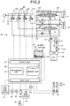
FIG. 2 is a diagram illustrating a control system for controlling operation of thework machine 5. A control system CS for controlling operation of thework machine 5 illustrated inFIG. 1 , that is, operation of theboom 3 and thebucket 4, includes a work machinehydraulic pump 12, aboom operation valve 13, abucket operation valve 14, apilot pump 15, adischarge circuit 12C, an electromagneticproportional control valve 20, acontrol device 40, a TM (transmission)control device 49, and an EG (engine) control device 51. - The work machine
hydraulic pump 12 is driven by an engine (EG) 60 as a power generator mounted on thewheel loader 1. Theengine 60 is an internal combustion engine, and in the present embodiment, it is a diesel engine. The type of theengine 60 is not limited to a diesel engine. The power of theengine 60 is input to a PTO (Power Take Off) 61, and then output to the work machinehydraulic pump 12 and to a clutch 62 as a power transmission mechanism. With this structure, the work machinehydraulic pump 12 is driven by theengine 60 via thePTO 61, and discharges hydraulic oil. - The input side of the clutch 62 is connected with the
engine 60, and the output side of the clutch 62 is connected with a torque converter (TC) 63. The output side of thetorque converter 63 is connected with a transmission (TM) 64. With this structure, the power of theengine 60 is transmitted to thetransmission 64 via thePTO 61, the clutch 62, and thetorque converter 63. Thetransmission 64 transmits the power of theengine 60, transmitted from thePTO 61, to thefront wheels 6F and therear wheels 6R shown inFIG. 1 , and drives them. Thewheel loader 1 and thevehicle body 2 travel with thefront wheel 6F and therear wheel 6R being driven by the output of theengine 60. Thefront wheels 6F and therear wheels 6R work as drive wheels of thewheel loader 1. - The discharge port, from which the work machine
hydraulic pump 12 discharges hydraulic oil, is connected with thedischarge circuit 12C working as an oil passage through which the hydraulic oil passes. Thedischarge circuit 12C is connected with theboom operation valve 13 and thebucket operation valve 14. Both theboom operation valve 13 and thebucket operation valve 14 are hydraulic pilot type operation valves. Theboom operation valve 13 and thebucket operation valve 14 are connected with theboom cylinder 9 and thebucket cylinder 10, respectively. The work machinehydraulic pump 12, theboom operation valve 13, thebucket operation valve 14, and thedischarge circuit 12C constitute a tandem hydraulic circuit. - The
boom operation valve 13 is a four-way selector valve having a position A, a position B, a position C, and a position D. Theboom operation valve 13 is configured such that theboom 3 moves up at the position A, theboom 3 is neutral and maintains the position at the position B, theboom 3 moves down at the position C, and theboom 3 floats at the position D. Thebucket operation valve 14 is a three-way selector value having a position E, a position F, and a position G. Thebucket operation valve 14 is configured such that thebucket 4 performs tilting at the position E, thebucket 4 is neutral and maintains the position at the position F, and thebucket 4 performs dumping at the position G. - The tilting of the
bucket 4 is an operation that theopening 4H and theclaw 4C of thebucket 4 shown inFIG. 1 turn toward the driver'scabin 7 to thereby be tilted. The dumping of thebucket 4 is an operation that theopening 4H and theclaw 4C of thebucket 4 turn away from the driver'scabin 7, in opposite to the tilting, to thereby be tilted. - Each of the pilot pressure receiving parts of the
boom operation valve 13 and thebucket operation valve 14 is connected with thepilot pump 15 via the electromagneticproportional control valve 20. Thepilot pump 15 is connected with thePTO 61, and is driven by theengine 60. Thepilot pump 15 supplies hydraulic oil of a predetermined pressure (pilot pressure) to a pilotpressure receiving part 13R of theboom operation valve 13 and a pilotpressure receiving part 14R of thebucket operation valve 14 via the electromagneticproportional control valve 20. - The electromagnetic
proportional control valve 20 includes a boom lowering electromagneticproportional control valve 21, a boom raising electromagneticproportional control valve 22, a bucket dump electromagneticproportional control valve 23, and a bucket tilt electromagneticproportional control valve 24. The boom lowering electromagneticproportional control valve 21 and the boom raising electromagneticproportional control valve 22 are connected with the respective pilotpressure receiving parts boom operation valve 13. The bucket dump electromagneticproportional control valve 23 and the bucket tilt electromagneticproportional control valve 24 are connected with the respective pilotpressure receiving part bucket operation valve 14. To asolenoid command part 21S of the boom lowering electromagneticproportional control valve 21, asolenoid command part 22S of the boom raising electromagneticproportional control valve 22, asolenoid command part 23S of the bucket dump electromagneticproportional control valve 23, and asolenoid command part 24S of the bucket tilt electromagneticproportional control valve 24, respective command signals from thecontrol device 40 are input. - The boom lowering electromagnetic
proportional control valve 21, the boom raising electromagneticproportional control valve 22, theboom operation valve 13, and theboom cylinder 9 have a function as a boom driving part to turn (move up and down) theboom 3. The bucket dump electromagneticproportional control valve 23, the bucket tilt electromagneticproportional control valve 24, thebucket operation valve 14, and thebucket cylinder 10 have a function as a bucket driving part to turn the bucket (perform tilting or dumping). - The
control device 40 includes a processing unit 41 such as a CPU (Central Processing Unit), amemory unit 42 such as a ROM (Read Only Memory), aninput unit 43, and anoutput unit 44. The processing unit 41 sequentially executes various types of commands described in a computer program to thereby control operation of thework machine 5. The processing unit 41 is electrically connected with thememory unit 42, theinput unit 43, and theoutput unit 44. With this structure, the processing unit 41 is able to read information stored in thememory unit 42, write information in thememory unit 42, receives information from theinput unit 43, and output information to theoutput unit 44. - The
memory unit 42 stores a computer program for controlling the operation of thework machine 5 and information for controlling the operation of thework machine 5. In the present embodiment, thememory unit 42 stores a computer program for realizing a work vehicle control method according to the present embodiment. The processing unit 41 reads the computer program from thememory unit 42 and executes it to thereby implement the work vehicle control method according to the present embodiment. - The
input unit 43 is connected with a boomangle detection sensor 46, a bucketangle detection sensor 47, a boomcylinder pressure sensor 48 which detects pressure (bottom pressure) of the hydraulic oil filling theboom cylinder 9, theTM control device 49 which controls thetransmission 64, avehicle speed sensor 50, the engine control device 51 which controls theengine 60, afirst potentiometer 31, and asecond potentiometer 33. The processing unit 41 obtains detection values or command values thereof, and controls the operation of thework machine 5. - In the present embodiment, a stroke of the
boom cylinder 9 and a stroke of thebucket cylinder 10 are obtained from the angle of theboom 3 detected by the boomangle detection sensor 46 and the angle of thebucket 4 detected by the bucketangle detection sensor 47 or the angle of thebell crank 11. Thecontrol device 40 obtains at least one of a stroke of theboom cylinder 9 or a stroke of thebucket cylinder 10 using at least one of the boomangle detection sensor 46 and the bucketangle detection sensor 47 to thereby control the operation of theboom 3 and thebucket 4. - The
vehicle speed sensor 50 as a vehicle speed detection device detects a speed (vehicle speed) at which thewheel loader 1 travels. Thevehicle speed sensor 50 may obtain the vehicle speed of thewheel loader 1 from the rotational speed of the output shaft of thetransmission 64 shown inFIG. 2 , for example. TheTM control device 49 shifts the gear stage of thetransmission 64. In that case, theTM control device 49 controls the gear stage based on the vehicle speed obtained from thevehicle speed sensor 50, the accelerator position of thewheel loader 1, and the like, for example. The engine control device 51 controls the amount of fuel supplied to theengine 60 based on the accelerator position and the engine speed of theengine 60, for example, to thereby control the power of theengine 60. In the present embodiment, a computer can be used for either theTM control device 49 or the engine control device 51. - The
output unit 44 is connected with thesolenoid command part 21S of the boom lowering electromagneticproportional control valve 21, thesolenoid command part 22S of the boom raising electromagneticproportional control valve 22, thesolenoid command part 23S of the bucket dump electromagneticproportional control valve 23, thesolenoid command part 24S of the bucket tilt electromagneticproportional control valve 24, and an input/output device 45. The processing unit 41 gives a command value for operating theboom cylinder 9 to thesolenoid command part 21S of the boom lowering electromagneticproportional control valve 21 or thesolenoid command part 22S of the boom raising electromagneticproportional control valve 22 to thereby extend or contract theboom cylinder 9. With extension or contraction of theboom cylinder 9, theboom 3 moves up and down. The processing unit 41 gives a command value for operating theboom cylinder 9 to thesolenoid command part 23S of the bucket dump electromagneticproportional control valve 23 or thesolenoid command part 24S of the bucket tilt electromagneticproportional control valve 24 to thereby extend or contract thebucket cylinder 10. With extension or contraction of thebucket cylinder 10, thebucket 4 performs tilting or dumping. In this way, the processing unit 41 controls operation of thework machine 5, that is, operation of theboom 3 and thebucket 4. - The input/
output device 45, connected with both theinput unit 43 and theoutput unit 44, includes aninput device 45S, asound generation device 45B, and adisplay device 45M. The input/output device 45 is configured to input a command value from theinput device 45S to thecontrol device 40, generate an alarm sound from thesound generation device 45B, display a state of thework machine 5 or information relating to the control of thework machine 5 on thedisplay device 45M, and the like. Theinput device 45S may be a push-button switch, for example. When theinput device 45S is operated, information displayed on thedisplay device 45M is switched, or the operation mode of thewheel loader 1 is switched. - The control lever CL as an operation device includes a
boom control lever 30 and abucket control lever 32. Theboom control lever 30 is a device for operating theboom 3. Theboom control lever 30 is equipped with thefirst potentiometer 31 which detects the operation amount with respect to theboom control lever 30. Thebucket control lever 32 is a device for operating thebucket 4. Thebucket control lever 32 is equipped with thesecond potentiometer 33 which detects the operation amount with respect to thebucket control lever 32. Detection signals of thefirst potentiometer 31 and thesecond potentiometer 33 are input to theinput unit 43 of thecontrol device 40. Aselector lever 18L of thetransmission 64 is used for shifting the gear stage of thetransmission 64, switching between moving forward and backward, and the like. -
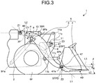
FIG. 3 is a diagram illustrating thework machine 5.FIG. 4 is a diagram for explaining tilting and dumping of thebucket 4 provided to thewheel loader 1. As illustrated inFIG. 3 andFIG. 4 , theboom 3 of thework machine 5 is pin-connected, on a first end side thereof, with thevehicle body 2 by a connectingpin 3P. Between the both ends of theboom 3, a bracket 3BR for mounting theboom cylinder 9 is attached. Theboom cylinder 9 is mounted such that a first end thereof is pin-connected with thevehicle body 2 by a connecting pin 9Pa, and a second end thereof is pin-connected with the bracket 3BR by a connecting pin 9Pb. With this structure, when theboom cylinder 9 is extended or contracted, theboom 3 turns (moves up and down) about a central axis Z1 of the connectingpin 3P. Specifically, theboom 3 is raised when theboom cylinder 9 is extended, while theboom 3 is lowered when theboom cylinder 9 is contracted. - The
bucket 4 is pin-connected with the second end side of theboom 3, that is, an end side opposite to thevehicle body 2 side (an end side away from the vehicle body 2), by a connecting pin 4Pa. With this structure, thebucket 4 turns about a central axis Z2 of the connecting pin 4Pa. Thebucket cylinder 10 is configured such that a first end thereof is pin-connected with thevehicle body 2 by the connectingpin 3P, and a second end thereof is pin-connected with a first end of the bell crank 11 by a connectingpin 11a. A second end of the bell crank 11 is pin-connected with a first end of a connectingmember 11L by a connectingpin 11b. A second end of the connectingmember 11L is pin-connected with thebucket 4 by a connecting pin 4Pb. - The
boom 3 has asupport member 8 which supports the bell crank 11, between the both ends. Thebell crank 11 is pin-connected, at the part between the both ends, with thesupport member 8 by a connectingpin 11c. With this structure, the bell crank 11 turns about a central axis Z3 of the connectingpin 11c. When thebucket cylinder 10 is contracted, the first end of the bell crank 11 moves to thevehicle body 2 side. As the bell crank 11 turns about the central axis Z3 of the connectingpin 11c, the second end of the bell crank 11 moves in a direction away from thevehicle body 2. Then, thebucket 4 performs dumping via the connectingmember 11L. When thebucket cylinder 10 is extended, the first end of the bell crank 11 moves away from thevehicle body 2 side. Then, as the second end of the bell crank 11 comes close to thevehicle body 2, thebucket 4 performs tilting via the connectingmember 11L. - On the second end side of the
boom 3, a stopper of the dump side (hereinafter referred to as a dump stopper as appropriate) STPD, which regulates the dumping of thebucket 4, is provided. The dump stopper STPD comes in contact with thebucket 4 to thereby prevent excessive dumping of thebucket 4. The position of thebucket 4, when thebucket 4 is in contact with the dump stopper STPD, is called a dump end. On the side opposite to thebucket 4 of the bell crank 11, a stopper on the tilt side (hereinafter referred to as a tilt stopper as appropriate) STPT, which regulates the tilting of thebucket 4, is provided. The tilt stopper STPT comes in contact with thebucket 4 to thereby prevent excessive tilting of thebucket 4. The position of thebucket 4, when the bucket is in contact with the tilt stopper STPT, is called a tilt end. In the present embodiment, while the dump stopper STPD is used to regulate the dumping of thebucket 4, the present invention is not limited to this. For example, a stroke end of thebucket cylinder 10 may regulates the dumping of thebucket 4, instead of the dump stopper STPD. Thebucket 4 is configured such that dumping stops at the stop position on the dump side. In the present embodiment, the stop position on the dump side may be the position of the dump stopper STPD or the position of the stroke end of thebucket cylinder 10, for example. - In the
work machine 5, the angle of the boom 3 (hereinafter referred to as a boom angle) α is a small one of angles between a line L1 linking the central axis Z1 of the connectingpin 3P and the central axis Z2 of the connecting pin 4Pa, and a horizontal line L2 passing through the connectingpin 3P parallel to the grounding surface of thefront wheels 6F and therear wheels 6R. In the present embodiment, the boom angle α becomes negative if theboom 3 is tilted toward a road surface R side from the horizontal line L2. When theboom 3 moves up, the boom angle α increases. - The angle of the bucket 4 (hereinafter referred to as a bucket angle as appropriate) β is an angle between the road surface R (corresponding to the horizontal line L2 in
FIG. 3 ) and a line L3 passing through the central axis Z2 of the connecting pin 4Pa parallel to abottom surface 4B of thebucket 4. In the present embodiment, the bucket angle β is negative if the front side of the line L3 is directed downward with respect to the central axis Z2 of the connecting pin 4Pa. When thebucket 4 performs tilting, the bucket angle β increases. - The boom
angle detection sensor 46 which detects the boom angle α is provided to the part of the connectingpin 3P for pin-connecting theboom 3 with thevehicle body 2. The bucketangle detection sensor 47 which detects the bucket angle β is provided to the part of the connectingpin 11c, and indirectly detects the angle of thebucket 4 via thebell crank 11. The bucketangle detection sensor 47 may be provided to the part of the connecting pin 4Pa which connects theboom 3 and thebucket 4. In the present embodiment, while potentiometers are used as the boomangle detection sensor 46 and the bucketangle detection sensor 47, for example, the present invention is not limited to this. - The boom angle α detected by the boom
angle detection sensor 46 serves as an index indicating the posture of theboom 3. As such, the boomangle detection sensor 46 works as a boom posture detection device which detects the posture of theboom 3. The bucket angle β detected by the bucketangle detection sensor 47 serves as an index indicating the posture of thebucket 4. As such, the bucketangle detection sensor 47 works as a bucket posture detection device which detects the posture of thebucket 4. - When the operator of the
wheel loader 1 operates theboom control lever 30 or thebucket control lever 32, thecontrol device 40 obtains a signal of the operation amount of theboom control lever 30 or thebucket control lever 32 from thefirst potentiometer 31 or thesecond potentiometer 33. Then, thecontrol device 40 outputs a work machine speed control command, corresponding to the signal of the operation amount, to the boom lowering electromagneticproportional control valve 21, the boom raising electromagneticproportional control valve 22, the bucket dump electromagneticproportional control valve 23, or the bucket tilt electromagneticproportional control valve 24. - The boom lowering electromagnetic
proportional control valve 21, the boom raising electromagneticproportional control valve 22, the bucket dump electromagneticproportional control valve 23, or the bucket tilt electromagneticproportional control valve 24 outputs a pilot pressure corresponding to the magnitude of the work machine speed control command, to the pilot pressure receiving part of the correspondingboom operation valve 13 or thebucket operation valve 14. Then, theboom cylinder 9 or thebucket cylinder 10 is operated in a corresponding direction at a speed corresponding to the respective pilot oil pressure. - The
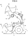
wheel loader 1 enters into dirt, crushed stones, or the like at a lower position DU illustrated inFIG. 4 , that is, a position where theclaw 4C of thebucket 4 comes close to the road surface R. At this time, thewheel loader 1 extends thebucket cylinder 10 so as to allow thebucket 4 to perform tilting to thereby scoop dirt, quarried stones, or the like into thebucket 4. Tilting is an operation that theclaw 4C of thebucket 4 is separated from the road surface R and moves toward the bell crank 11 side (operation to move in a direction shown by an arrow TL inFIG. 4 ). - The
wheel loader 1 raises theboom 3 to thereby lift thebucket 4 which scooped dirt, quarried stones, or the like to an upper position UP, and load the dirt, crushed stores, or the like on a vessel of the dump truck, for example. When loading the dirt, crushed stones, or the like, thewheel loader 1 contracts thebucket cylinder 10 so as to allow thebucket 4 to perform dumping to thereby cause theclaw 4C of thebucket 4 to face downward. Then, the dirt, crushed stones, or the like, held by thebucket 4, is released from thebucket 4 to the vessel. Dumping is an operation that theclaw 4C of thebucket 4 moves downward (operation to move in a direction shown by an arrow DP inFIG. 4 ). - When the
bucket 4 performs dumping, thebucket 4 comes in contact with the dump stopper STPD illustrated inFIG. 3 . At this time, an impact may be generated. As such, in the present embodiment, control to suppress the impact, as described above, is performed when thebucket 4 performs dumping. Further, when theboom 3 is raised, even though thebucket 4 is not operated, thebucket 4 may be in contact with the dump stopper STPD illustrated inFIG. 3 during rising of theboom 3, depending on the posture of the bell crank 11, the posture of theboom 3, and a state of the length of thebucket cylinder 10. If theboom 3 is raised in such a state, thebucket 4 receives reaction force from the dump stopper STPD. Therefore, in the present embodiment, thebucket 4 is caused to perform tilting automatically if needed, at the time of rising of theboom 3. -
FIG. 5 is a drawing illustrating an example of a first table TBA for control to be used for control at the time of dumping in the work vehicle control method according to the present embodiment.FIG. 6 is a drawing illustrating an example of a second table TBA for control to be used for control at the time of dumping in the work vehicle control method according to the present embodiment.FIG. 7 is a drawing illustrating a relationship between a limit rate LQ of a boom rising speed and a reach distance SCR of thebucket cylinder 10. Reference signs a, b, c, and d inFIG. 5 and FIG. 6 correspond to lines a, b, c, and d inFIG. 7 , in this order. - At the time of dumping by the
bucket 4, an operating speed when thebucket 4 is operated is limited corresponding to the distance up to a point where thebucket 4 comes in contact with the dump stopper STPD. This control is called dumping impact suppression control, as appropriate. The dumping of thebucket 4 is performed even during rising of theboom 3. In that case, dumping by thebucket 4 is performed as a complex operation with theboom 3. The rising speed of theboom 3 varies depending on the condition of the work site. If the operating speed of thebucket 4 is limited uniformly, suppression of an impact may become insufficient, or the productivity may be lowered. Further, as an operation similar to the dumping, there is a process to turn thebucket 4 upward and downward in turn so as to cause thebucket 4 to bump into the dump stopper STPD to thereby drop the mud or the like (hereinafter referred to as mud dropping, as appropriate) attached to thebucket 4. If the operating speed, when thebucket 4 is operated, is limited by the dumping impact suppression control, an impact when thebucket 4 bumps into the dump stopper STPD is suppressed. Consequently, the mud dropping process may be insufficient, or mud dropping process may take time. - The
control device 40 illustrated inFIG. 2 is configured such that at the time of dumping by thebucket 4, thecontrol device 40 performs the dumping impact suppression control according to the work vehicle control method of the present embodiment, to thereby suppress an impact generated at the time of dumping by thebucket 4, and operate thebucket 4 according to the intention of the operator. In the present embodiment, when thebucket 4 performs dumping, thecontrol device 40 obtains a operable amount that thebucket cylinder 10 is able to operate before thebucket 4 reaches the dump stopper STPD based on the posture of theboom 3 and the posture of thebucket 4, and the operation amount for raising theboom 3 or the rising speed of theboom 3. Then, thecontrol device 40 limits the operating speed of thebucket cylinder 10 according to the operable amount that thebucket cylinder 10 is able to operate before thebucket 4 reaches the dump stopper STPD, and based on the obtained operation amount for raising theboom 3 or the rising speed of theboom 3, changes the limit amount of the operating speed of thebucket cylinder 10. - The operable amount of the
bucket cylinder 10 before thebucket 4 reaches the dump stopper STPD is represented by a distance up to a position where thebucket 4 reaches the dump stopper STPD (hereinafter referred to as a reach distance as appropriate). If the reach distance is represented as SCR, it is a value calculated by subtracting the current length (entire length) of thebucket cylinder 10, from a length (entire length) of thebucket cylinder 10 when thebucket 4 reaches the dump stopper STPD at a boom angle α. - As the positional relationship among the
boom 3, the bell crank 11, and thebucket 4 is changed according to the boom angle α, the reach distance SCR is also changed according to the boom angle α. In the present embodiment, thememory unit 42 of thecontrol device 40 illustrated inFIG. 2 stores the length of thebucket cylinder 10 when thebucket 4 reaches the dump stopper STPD (hereinafter referred to as a length when reached), which is calculated for each of a plurality of boom angles α, for example. When calculating the reach distance SCR, the processing unit 41 of thecontrol device 40 obtains the boom angle α and the bucket angle β or the angle of the bell crank 11 at the current point from the boomangle detection sensor 46 and the bucketangle detection sensor 47 illustrated inFIG. 2 andFIG. 3 , and calculates the length of the bucket cylinder at the current point. Then, the processing unit 41 obtains the length when reached corresponding to the obtained boom angle α, and subtracts the length of the bucket cylinder at the current point, from the obtained length when reached. In this way, the processing unit 41 is able to calculate the reach distance SCR. - The first table TBA illustrated in
FIG. 5 and the second table TBB illustrated inFIG. 6 describe the limit rate LQ for determining the limit amount of the operating speed of thebucket cylinder 10, to be used for control at the time of dumping by thebucket 4. The first table TBA and the second table TBB illustrated inFIG. 6 describe the limit rate LQ with respect to the reach distance SCR, for each operation amount BVC of an operation to raise the boom 3 (hereinafter referred to as boom raising as appropriate). At the time of dumping, as thebucket cylinder 10 is contracted, the reach distance SCR is represented by a negative sign, as illustrated inFIG. 5 and FIG. 6 . As the absolute value of the reach distance SCR becomes smaller, the distance up to a point where thebucket 4 reaches the dump stopper STPD becomes shorter. When the reach distance SCR is zero, thebucket 4 reaches the dump stopper STPD. - The operation amount for raising the boom (hereinafter referred to as a boom raising operation amount as appropriate) BVC is an operation amount of the
boom control lever 30 illustrated inFIG. 2 . When the boom raising operation amount BVC increases, the flow rate of the hydraulic oil supplied to theboom cylinder 9 illustrated inFIG. 1 andFIG. 2 increases. Consequently, the rising speed of theboom 3 increases. The boom raising operation amount BVC is 100% when the operation amount of theboom control lever 30 at the time of raising theboom 3 is maximum, and is 0% when theboom control lever 30 is neutral. In the first table TBA and the second table TBB, while the reach distance SCR is described for each of the three stages where the boom raising operation amount BVC is 0%, 50%, and 100%, for a case where the boom raising operation amount BVC is between 0% and 50% and between 50% and 100%, the limit rate LQ can be obtained by interpolation, for example. - The operating speed of the
bucket cylinder 10 varies according to the flow rate of the hydraulic oil supplied to thebucket cylinder 10. In the present embodiment, the operating speed of thebucket cylinder 10 is limited by limiting the target flow rate of the hydraulic oil supplied to thebucket cylinder 10 at the time of dumping (hereinafter referred to as dump time target flow rate as appropriate). The dump time target flow rate is determined by the operation amount of thebucket control lever 32 illustrated inFIG. 2 . - If the dump time target flow rate is represented as QTd, and the operation amount of the
bucket control lever 32 at the time of dumping (hereinafter referred to as bucket dump operation amount, as appropriate) is represented as QBKd, as the bucket dump operation amount QBKd increases, the dump time target flow rate QTd also increases, and consequently, the speed at the time of dumping by thebucket 4 also becomes higher. The bucket dump operation amount QBKd is 100% when the operation amount of thebucket control lever 32 for causing thebucket 4 to dump is maximum, and is 0% when thebucket control lever 32 is neutral. - In the present embodiment, at the time of dumping, the
control device 40 controls the operation of thebucket cylinder 10 using a corrected dump time target flow rate QTdc calculated by multiplying the dump time target flow rate QTd, determined by the bucket dump operation amount QBKd, by the limit rate LQ. Consequently, the operating speed of thebucket cylinder 10 becomes smaller compared with the case before it is limited by the limit rate LQ. - The limit rates LQ described in the first table TBA illustrated in
FIG. 5 and the second table TBB illustrated inFIG. 6 are expressed in percentages. For example, when the limit rate LQ is 100%, the corrected dump time target flow rate QTdc equals to the dump time target flow rate QTd, and when the limit rate LQ is 60%, the corrected dump time target flow rate QTdc becomes 60% of the dump time target flow rate QTd. When the limit rate LQ is 15%, the corrected dump time target flow rate QTdc becomes 15% of the dump time target flow rate QTd. Accordingly, as the limit rate LQ is smaller, the degree that the corrected dump time target flow rate QTdc becomes smaller than the dump time target flow rate QTd is larger. Thus, as the limit rate LQ is smaller, the limit amount of the operating speed of thebucket cylinder 10 becomes larger. - Regarding the first table TBA in
FIG. 5 and the second table TBB inFIG. 6 , either one is used based on the operable amount that thebucket cylinder 10 is able to operate before thebucket 4 reaches the dump stopper STPD (hereinafter referred to as operating time operable amount, as appropriate) when the condition for executing the dumping impact suppression control is satisfied. If the operating time operable amount is represented as SCRm, in the case where the operating time operable amount SCRm is a predetermined value SCRc or larger, the first table TBA is used for the dumping impact suppression control, while in the case where the operating time operable amount SCRm is smaller than the predetermined value SCRc, the second table TBB is used for the dumping impact suppression control. - If the boom raising operation amount BVC in the first table TBA illustrated in
FIG. 5 is 0%, the limit rate LQ varies as a line "a" illustrated inFIG. 7 according to the change of the reach distance SCR. If the boom raising operation amount BVC in the second table TBB illustrated inFIG. 6 is 0%, the limit rate LQ varies as a line "d" illustrated inFIG. 7 according to the change of the reach distance SCR. If the boom raising operation amount BVC in the first table TBA and the second table TBB is 50%, the limit rate LQ varies as a line "b" illustrated inFIG. 7 according to the change of the reach distance SCR. If the boom raising operation amount BVC in the first table TBA and the second table TBB is 100%, the limit rate LQ varies as a line "c" illustrated inFIG. 7 according to the change of the reach distance SCR. - In the first table TBA, the limit rate LQ becomes smaller as the reach distance SCR becomes shorter, that is, the distance up to a point where the
bucket 4 reaches the dump stopper STPD becomes shorter. This means that as thebucket 4 comes closer to the dump stopper STPD, the limit amount of the operating speed of the actuator becomes larger, and the operating speed of thebucket cylinder 10 becomes lower. - In the second table TBB, when the boom raising operation amount BVC is not zero (0%), as the limit rate LQ becomes smaller as the reach distance SCR becomes shorter, the limit amount of the operating speed of the actuator becomes larger, and the operating speed of the
bucket cylinder 10 becomes lower. Theboom 3 is raised when the boom raising operation amount BVC is not zero (0%), and theboom 3 stops when the boom raising operation amount BVC is zero (0%). - In the first table TBA and the second table TBB, as the
bucket 4 comes closer to the dump stopper STPD, the operating speed of thebucket cylinder 10 becomes lower. As such, by executing the dumping impact suppression control using the first table TBA and the second table TBB, thecontrol device 40 is able to suppress an impact at the dump end when thebucket 4 comes in contact with the dump stopper STPD. - When the boom raising operation amount BVC is zero (0%), that is, when the
boom 3 has stopped, in the second table TBB, the limit rate LQ is 100% regardless of the reach distance SCR. As such, when the boom raising operation amount BVC is zero (0%), the limit amount of the operating speed of thebucket cylinder 10 is zero, whereby hydraulic oil is supplied to thebucket cylinder 10 at the dump time target flow rate QTd determined according to the bucket dump operation amount QBKd. Consequently, the operating speed of thebucket cylinder 10 is not limited, and the operating speed corresponding to the operation of thebucket control lever 32 by the operator is realized. - In the first table TBA and the second table TBB, if the reach distance SCR is the same, when the boom raising operation amount BVC is changed from 100% to 0%, the limit rate LQ becomes larger, and when the boom raising operation amount BVC is changed from 0% to 100%, the limit rate LQ becomes smaller. This means that in the first table TBA and the second table TBB, the limit amount of the operating speed of the
bucket cylinder 10 is changed to be larger if the boom raising operation amount BVC is larger or the rising speed of theboom 3 is higher, and is changed to be smaller if the boom raising operation amount BVC is smaller or the rising speed of the boom is lower. - If the
bucket 4 comes in contact with the dump stopper STPD when the rising speed of theboom 3 is higher, an impact is larger, compared with the case where thebucket 4 comes in contact with the dump stopper STPD when the rising speed of theboom 3 is lower. Further, if theboom 3 is raised when thebucket 4 comes in contact with the dump stopper STPD, an impact may be caused at the dump end at the time of tilting of thebucket 4 or an operation to lower theboom 3, due to the hydraulic oil in thebucket cylinder 10 being pressurized. Such an impact is more remarkable as the rising speed of theboom 3 is higher. - According to the first table TBA and the second table TBB, by allowing the limit amount of the operating speed of the
bucket cylinder 10 to be larger as the boom raising operation amount BVC or the rising speed of theboom 3 is larger, it is possible to suppress an impact to be caused when thebucket 4 comes in contact with the dump stopper STPD during rising of theboom 3. Further, according to the first table TBA and the second table TBB, it is possible to suppress an impact to be caused at a dump end at the time of tilting of thebucket 4 or at the time of operation to lower theboom 3, due to the hydraulic oil in thebucket cylinder 10 being pressurized. - In the present embodiment, as the limit amount of the operating speed of the
bucket cylinder 10 is changed based on the boom raising operation amount BVC or the rising speed of theboom 3, the reduction amount of the operating speed of thebucket 4 is also changed. As such, the operating speed of thebucket 4 can be faster, compared with the case where the operating speed of thebucket cylinder 10 is limited uniformly in the dumping impact suppression control. In this way, as operation delay of thebucket 4 with respect to thebucket control lever 32 performed by the operator can be suppressed, a sense of discomfort felt by the operator can be suppressed, and a reduction in productivity can also be prevented. - In the present embodiment, the
control device 40 performs the dumping impact suppression control by using the second table TBA if the operating time operable amount SCRm is less than the predetermined value SCRc. If thebucket 4 performs dumping in a state where the operating time operable amount SCRm is less than the predetermined value SCRc and the boom raising operation amount BVC or the rising speed of theboom 3 is zero, it can be determined that the mud dropping, described above, is performed. For example, if the remaining length of thebucket cylinder 10, up to the point where thebucket 4 comes in contact with the dump stopper STPD, is about 100 mm, as it can be determined that mud dropping is performed, it can be set to 100 mm. As such, while the predetermined value SCRc may be set to 100 mm, for example, the present invention is not limited to this. - If the boom raising operation amount BVC or the rising speed of the
boom 3 is zero, in the second table TBB, as the limit rate LQ is 100% regardless of the reach distance SCR as described above, the operating speed of thebucket cylinder 10 is not limited, and thebucket 4 is operated at an operating speed corresponding to the operation of thebucket control lever 32 by the operator. As such, thecontrol device 40 releases the limit on the moving speed of thebucket cylinder 10. In this way, if it is determined that mud dropping is performed, as thecontrol device 40 does not limit the operating speed of thebucket cylinder 10, it is possible to cause thebucket 4 to bump into the dump stopper STPD vigorously to thereby drop the mud from thebucket 4 speedy and reliably. -
FIG. 8 is a flowchart illustrating exemplary control at the time of dumping in the work vehicle control method according to the present embodiment.FIG. 9 is a drawing for explaining determination to start and stop control at the time of dumping. When performing control at the time of dumping of thebucket 4, at step S101, thecontrol device 40 illustrated inFIG. 2 compares the bucket dump operation amount QBKd and a bucket dump operation amount threshold QBKdc. The bucket dump operation amount threshold QBKdc is a value larger than 0% and smaller than 100%. In the present embodiment, it is 30%, for example. The bucket dump operation amount threshold QBKdc is not limited to 30%. - If the bucket dump operation amount QBKd is the bucket dump operation amount threshold QBKdc or larger (step S101, Yes), the process proceeds to step S102, and the
control device 40 determines whether or not the operation of theboom 3 is an operation other than the boom lowering operation. An operation other than the boom lowering operation means either rising of theboom 3 or a stop of theboom 3. If the operation of theboom 3 is other than the boom lowering operation (step S102, Yes), the process proceeds to step S103, and thecontrol device 40 compares the operating time operable amount SCRm and a predetermined value SCRc. In that case, thecontrol device 40 obtains the operating time operable amount SCRm based on the posture of theboom 3 and the posture of thebucket 4 at the time when an operation to cause thebucket 4 to perform dumping is started with respect to thebucket control lever 32 for operating thebucket 4. - If the operating time operable amount SCRm is the predetermined value SCRc or larger (step S103, Yes), the process proceeds to step S104, and the
control device 40 uses the first table TBA to perform dumping impact suppression control. If the operating time operable amount SCRm is smaller than the predetermined value SCRc (step S103 No), the process proceeds to step S105, and thecontrol device 40 uses the second table TBB to perform control in dumping. In that case, as it is determined that mud dropping is performed, thecontrol device 40 does not perform dumping impact suppression control, and the hydraulic oil is supplied to thebucket cylinder 10 so as to realize the dump time target flow rate calculated from the operation amount of thebucket control lever 32. When step S104 and S105 end, thecontrol device 40 goes back to the start and performs the process after step S101. - At step S101, if the bucket dump operation amount QBKd is less than the bucket dump operation amount threshold QBKdc (step S101, No), the
control device 40 does not perform dumping impact suppression control, and goes back to the start and performs the process after step S101. - In the present embodiment, the
control device 40 performs dumping impact suppression control if the bucket dump operation amount QBKd is the bucket dump operation amount threshold QBKdc or larger, which is one of the conditions. In the dumping impact suppression control, if the operator operates thebucket control lever 32 and the bucket dump operation amount QBKd becomes less than the bucket dump operation amount threshold QBKdc (step S101), the dumping impact suppression control is not performed. If an input is given to thebucket control lever 32 by which the bucket dump operation amount QBKd becomes close to the bucket dump operation amount threshold QBKdc, there is a possibility of occurrence of a hunting phenomenon in which execution and suppression of the dumping impact suppression control is performed in turn. - As such, as illustrated in
FIG. 9 , a condition that the bucket dump operation amount QBKd becomes the bucket dump operation amount threshold QBKdc or larger may be required for starting the dumping impact suppression control, while a condition that the bucket dump operation amount QBKd becomes a suspension determination threshold QBKdd or smaller may be required for suspending the dumping impact suppression control. The suspension determination threshold QBKdd is smaller than the bucket dump operation amount threshold QBKdc. In this way, the above-described hunting can be prevented. - If the bucket dump operation amount QBKd is small, even if the
bucket 4 performs dumping to thereby come in contact with the dump stopper STPD, the operating speed of thebucket 4 is small, so that an impact is also small. If an impact when thebucket 4 comes in contact with the dump stopper STPD has a magnitude which is of an allowable level, it is possible to improve the productivity and operability by not performing the dumping impact suppression control. In the present embodiment, a condition that the bucket dump operation amount QBKd becomes the bucket dump operation amount threshold QBKdc or larger is taken as a condition for starting the dumping impact suppression control. With this configuration, if the bucket dump operation amount QBKd has a magnitude in which an impact when thebucket 4 comes in contact with the dump stopper STPD is in an allowable level, it is possible to improve the productivity and operability by not performing the dumping impact suppression control. -
FIG. 10 is a drawing illustrating an example of an automatic tilt table TBC to be used for control when the bucket is caused to perform tilting automatically in the work vehicle control method according to the present embodiment.FIG. 11 is a diagram illustrating the relationship between a tilt command CC and the reach distance SCR of thebucket cylinder 10. - In the
wheel loader 1 illustrated inFIG. 1 , the length of thebucket cylinder 10 is constant when thebucket 4 is not operated at all, that is, when the operation of thebucket 4 is stopped. As such, if theboom 3 is raised when thebucket 4 is stopped, the positional relation between thebucket 4 and theboom 3 is changed along with rising of theboom 3, whereby thebucket 4 may come in contact with the dump stopper STPD illustrated inFIG. 3 . If thebucket 4 comes in contact with the dump stopper STPD when theboom 3 is being raised in a state where thebucket 4 is not operated, excessive loads may be acted on the link mechanism of thework machine 5, thebucket cylinder 10, theboom cylinder 9, and the like. - As such, if the
bucket control lever 32 is neutral, that is, if the operation amount of thebucket control lever 32 is zero (0%), when theboom 3 is raised, thecontrol device 40 illustrated inFIG. 2 performs control to cause thebucket 4 to perform tilting automatically. This control is called automatic tilt. The automatic tilt is performed when thebucket 4 is stopped, that is, in the case where thebucket control lever 32 is neutral. With the automatic tilt, the loads placed on the link mechanism of thework machine 5, thebucket cylinder 10, theboom cylinder 9, and the like are reduced. When thebucket 4 performs tilting, thebucket cylinder 10 is contracted. - The automatic tilt is performed in a state where the
bucket 4 is stopped, that is, in a state where the operator does not operate thebucket control lever 32. When the automatic tilt is performed, as thebucket 4 is operated automatically, the operator may recognize that unintentional operation of thebucket 4 is caused and feel a sense of discomfort. As such, it is preferable that the operation of thebucket 4 in the automatic tilt should be kept to a requisite minimum. In order to keep the operation of thebucket 4 to a requisite minimum in the automatic tilt, it is only necessary that the length of thebucket cylinder 10 equals to the length when thebucket 4 comes in contact with the dump stopper STPD. Thecontrol device 40 illustrated inFIG. 2 makes the operation of the bucket 4 a requisite minimum by performing the automatic tilt by the work vehicle control method according to the present embodiment. - The automatic tilt table TBC illustrated in
FIG. 10 describes the relationship between the tilt command CC and the reach distance SCR of thebucket cylinder 10, for each boom raising operation amount BVC. Reference signs e, f, and g inFIG. 10 correspond to lines e, f, and g inFIG. 11 , in this order. In the automatic tilt table TBC, while the reach distance SCR is described with respect to each of the three stages where the boom raising operation amount BVC is 0%, 50%, and 100%, for the boom raising operation amount BVC between 0% and 50% and between 50% and 100%, the tilt command CC can be obtained by interpolation, for example. - If the boom raising operation amount BVC in the automatic tilt table TBC is 0%, the tilt command CC varies as a line "e" illustrated in
FIG. 11 , in accordance with the change of the reach distance SCR. If the boom raising operation amount BVC in the automatic tilt table TBC is 50%, the tilt command CC varies as a line "f" illustrated inFIG. 11 , in accordance with the change of the reach distance SCR. If the boom raising operation amount BVC in the automatic tilt table TBC is 100%, the tilt command CC varies as a line "g" illustrated inFIG. 11 , in accordance with the change of the reach distance SCR. - The tilt command CC is a command to cause the
bucket 4 to perform tilting, and is a command to change the operation amount of thebucket cylinder 10. Specifically, the operating speed of thebucket cylinder 10 is changed by the tilt command CC. For example, if the tilt command CC is -10, thebucket cylinder 10 is extended at an operating speed corresponding to the tilt command CC. The tilt command CC is configured such that as the absolute value thereof is larger, the operation amount of thebucket cylinder 10 to cause thebucket 4 to perform tilting, that is, an operating speed in the present embodiment, is larger. - The automatic tilt table TBC is configured such that as the absolute value of the reach distance SCR of the
bucket cylinder 10 is smaller, that is, as thebucket 4 comes closer to the dump stopper STPD, the tilt command CC is larger. Further, the automatic tilt table TBC is configured such that the tilt command CC is given when the boom raising operation amount BVC is larger than 0%. At the time of automatic tilt, thecontrol device 40 illustrated inFIG. 2 changes the tilt command CC based on the boom raising operation amount BVC or the rising speed of theboom 3 to thereby change the operation amount of thebucket cylinder 10 for making thebucket 4 tilt, and cause thebucket 4 to perform tilting corresponding to the reach distance SCR of thebucket cylinder 10. With this configuration, a contact between thebucket 4 and the dump stopper STPD is prevented during rising of theboom 3. - If the rising speed of the
boom 3 is higher, as thebucket 4 comes in contact with the dump stopper STPD faster than the case where the rising speed of theboom 3 is lower, even if the automatic tilt is performed, there is a possibility that a pressure contact between thebucket 4 and the dump stopper STPD occurs. In the present embodiment, the automatic tilt table TBC is configured such that as the boom raising operation amount BVC is larger or the rising speed of theboom 3 is higher, thebucket cylinder 10 is caused to be operated from a position where the reach distance SCR is large so as to cause thebucket 4 to perform tilting. As such, if the boom raising operation amount BVC is large or the rising speed of theboom 3 is high, as thebucket 4 performs tilting automatically at earlier timing, a pressure contact between thebucket 4 and the dump stopper STPD can be prevented reliably. - In the automatic tilt, the
control device 40 sets zero to the tilt command CC when the reach distance SCR is zero to thereby stop tilting of thebucket 4. In the automatic tilt table TBC, if the boom raising operation amount BVC is 0% or the rising speed of theboom 3 is zero, the tilt command CC is zero when the reach distance SCR is zero. However, if the boom raising operation amount BVC is 50% or 100%, the tilt command CC is -10. As such, if the boom raising operation amount BVC is 50% or 100%, even if the reach distance SCR is zero, thebucket 4 performs tilting. With this configuration, when the boom raising operation amount BVC becomes 0% or the rising speed of theboom 3 becomes zero during rising of theboom 3, thecontrol device 40 is able to stop thebucket 4 at a target position, that is, a position closer to a position where thebucket 4 comes in contact with the dump stopper STPD. Consequently, thecontrol device 40 is able to keep the operation of thebucket 4 in the automatic tilt to be a requisite minimum. Thereby, it is possible to reduce a sense of discomfort given to the operator. - If the boom raising operation amount BVC is larger than 0%, when the
boom 3 is raised, there is a possibility that intervention and non-intervention of automatic tilt may be repeated near the area where thebucket 4 and the dump stopper STPD contact with each other. In order to avoid this case, the automatic tilt table TBC is configured such that if the boom raising operation amount BVC is larger than 0%, a value other than zero (-10 in the present embodiment) is set to the tilt command CC, to thereby reduce the possibility that intervention and non-intervention of automatic tilt are repeated. Consequently, a sense of discomfort given to the operator in automatic tilt can be further reduced. -
FIG. 12 is a flowchart illustrating exemplary control at the time of automatic tilting in the work vehicle control method according to the present embodiment. In the work vehicle control method according to the present embodiment, when executing automatic tilting of thebucket 4, at step S201, thecontrol device 40 illustrated inFIG. 2 determines that thebucket 4 is neutral, that is, thebucket 4 is not operated. If thebucket control lever 32 illustrated inFIG. 2 is neutral, thebucket 4 is neutral. Thecontrol device 40 determines whether or not thebucket control lever 32 is in a neutral state from the detection value of thesecond potentiometer 33 illustrated inFIG. 2 . - If the
bucket 4 is neutral (step S201, Yes), the process proceeds to step S202, and thecontrol device 40 determines the boom raising operation, that is, whether or not theboom 3 is being raised or stopped. Thecontrol device 40 determines that theboom 3 is being raised or stopped if the boom raising operation amount BVC is 0% or larger. If theboom 3 is being raised (step S202, Yes), at step S203, thecontrol device 40 performs automatic tilting by using the automatic tilt table TBC. If thebucket 4 is not neutral (step S201, No) and theboom 3 is not being raised or stopped (step S202, No), thecontrol device 40 goes back to the start and performs the process after step S101. If theboom 3 is not being raised or stopped, it means theboom 3 is being lowered. - While the present embodiment has been described above, the present embodiment is not limited to that described above. Further, the above-described constituent elements include elements which are easily expected by those skilled in the art, which are substantially the same, and which are in the so-called equal scope. Further, the above-described constituent elements can be combined appropriately. Further, at least one of omission, replacement, and modification of various types of the constituent elements can be made within the scope without departing from the substance of the present embodiment.
-
- 1 wheel loader
- 2 vehicle body
- 3 boom
- 4 bucket
- 4C claw
- 5 work machine
- 7 driver's cabin
- 9 boom cylinder
- 10 bucket cylinder
- 11 bell crank
- 12 work machine hydraulic pump
- 20 electromagnetic proportional control valve
- 23 bucket dump electromagnetic proportional control valve
- 24 bucket tilt electromagnetic proportional control valve
- 30 boom control lever
- 32 bucket control lever
- 40 control device
- 41 processing unit
- 42 memory unit
- 46 boom angle detection sensor
- 47 bucket angle detection sensor
- 60 engine
- BVC operation amount
- CC tilt command
- CS control system
- LQ limit rate
- QBKd bucket dump operation amount
- QBKdc bucket dump operation amount threshold
- QBKdd suspension determination threshold
- QTd dump time target flow rate
- QTdc corrected dump time target flow rate
- SCR reach distance
- SCRc predetermined value
- SCRm operable amount (operating time operable amount)
- STPD dump stopper
- STPT tilt stopper
- TBA first table
- TBB second table
- TBC tilt table
Claims (4)
- A work vehicle control method comprising, in controlling a work vehicle (1) including a boom (3) supported by a vehicle body (2) and configured to turn; and a bucket (4) supported by a side, away from the vehicle body (2), of the boom (3) and configured to turn according to an operation of an actuator (10):obtaining an operation amount (BVC) for raising the boom (3) or a rising speed of the boom (3) and an operable amount (SCR) that the actuator (10) is able to operate before the bucket (4) reaches a stop position (STPD) on a dump side, the operable amount (SCR) being obtained based on a posture of the boom (3) and a posture of the bucket(4); characterized bycausing the bucket (4) to perform tilting by operating the actuator (10) from a position where the operable amount (SCR) reaches a threshold such that said threshold is increased depending on an increase of the operation amount (BVC) for raising the boom (3) or on an increase of the rising speed of the boom (3).
- The work vehicle control method according to Claim 1, further comprising
in a case where the boom (3) is raised and a device (32) for operating the bucket (4) is in a neutral state in which the bucket (4) is not operated, causing the bucket (4) to perform tilting according to the operable amount (SCR). - A work vehicle comprising:a boom (3) supported by a vehicle body (2) and configured to turn;a bucket (4) supported by a side, away from the vehicle body (2), of the boom (3), and configured to turn according to an operation of an actuator (10); anda work vehicle control device which controls the work vehicle (1), whereinthe work vehicle control device (40) obtains an operation amount (BVC) for raising the boom (3) or a rising speed of the boom (3), and an operable amount (SCR) that the actuator (10) is able to operate before the bucket (4) reaches a stop position (STPD) on a dump side, the operable amount (SCR) being obtained based on a posture of the boom (3) and a posture of the bucket (4), characterized in that the work vehicle control device (40) causes the bucket (4) to perform tilting by operating the actuator (10) from a position where the operable amount (SCR) reaches a threshold such that said threshold is increased depending on an increase of the operation amount (BVC) for raising the boom (3) or on an increase of the rising speed of the boom.
- The work vehicle according to Claim 3, wherein in a case where the boom (3) is raised and a device for operating the bucket (4) is in a neutral state in which the bucket (4) is not operated, the work vehicle control device (40) causes the bucket (4) to perform tilting according to the operable amount (SCR).
Applications Claiming Priority (1)
| Application Number | Priority Date | Filing Date | Title |
|---|---|---|---|
| PCT/JP2014/064540 WO2015102059A1 (en) | 2014-05-30 | 2014-05-30 | Method and device for controlling working vehicle, and working vehicle |
Publications (3)
| Publication Number | Publication Date |
|---|---|
| EP2933384A1 EP2933384A1 (en) | 2015-10-21 |
| EP2933384A4 EP2933384A4 (en) | 2015-12-02 |
| EP2933384B1 true EP2933384B1 (en) | 2017-07-05 |
Family
ID=53277420
Family Applications (1)
| Application Number | Title | Priority Date | Filing Date |
|---|---|---|---|
| EP14759087.1A Active EP2933384B1 (en) | 2014-05-30 | 2014-05-30 | Method and device for controlling working vehicle, and working vehicle |
Country Status (5)
| Country | Link |
|---|---|
| US (1) | US9809948B2 (en) |
| EP (1) | EP2933384B1 (en) |
| JP (1) | JP5717924B1 (en) |
| CN (1) | CN105324539B (en) |
| WO (1) | WO2015102059A1 (en) |
Families Citing this family (4)
| Publication number | Priority date | Publication date | Assignee | Title |
|---|---|---|---|---|
| CN106795705B (en) * | 2014-10-13 | 2019-05-28 | 山特维克矿山工程机械有限公司 | For controlling the arrangement of work mechanism |
| JP7232691B2 (en) * | 2019-03-29 | 2023-03-03 | 株式会社小松製作所 | Work machine and work machine control method |
| GB2589573A (en) | 2019-12-02 | 2021-06-09 | Caterpillar Inc | Bucket actuator assembly with resilient bump stop |
| WO2023189421A1 (en) * | 2022-03-31 | 2023-10-05 | 日立建機株式会社 | Work machine |
Family Cites Families (6)
| Publication number | Priority date | Publication date | Assignee | Title |
|---|---|---|---|---|
| JPS58218524A (en) * | 1982-06-08 | 1983-12-19 | Toyo Umpanki Co Ltd | Controller for loading and unloading vehicle |
| CN1078287C (en) * | 1997-06-20 | 2002-01-23 | 日立建机株式会社 | Device for controlling limited-area excavation with construction machine |
| JP2009197425A (en) | 2008-02-20 | 2009-09-03 | Komatsu Ltd | Construction machine |
| JP5133849B2 (en) | 2008-11-04 | 2013-01-30 | 株式会社細川洋行 | Medical multi-chamber container |
| WO2010110386A1 (en) * | 2009-03-26 | 2010-09-30 | 株式会社小松製作所 | Method for construction vehicle control and control device |
| JP5228132B1 (en) * | 2012-09-12 | 2013-07-03 | 株式会社小松製作所 | Wheel loader |
-
2014
- 2014-05-30 WO PCT/JP2014/064540 patent/WO2015102059A1/en active Application Filing
- 2014-05-30 EP EP14759087.1A patent/EP2933384B1/en active Active
- 2014-05-30 CN CN201480000861.8A patent/CN105324539B/en active Active
- 2014-05-30 JP JP2014528766A patent/JP5717924B1/en active Active
- 2014-05-30 US US14/385,603 patent/US9809948B2/en active Active
Non-Patent Citations (1)
| Title |
|---|
| None * |
Also Published As
| Publication number | Publication date |
|---|---|
| WO2015102059A1 (en) | 2015-07-09 |
| CN105324539A (en) | 2016-02-10 |
| EP2933384A4 (en) | 2015-12-02 |
| US9809948B2 (en) | 2017-11-07 |
| CN105324539B (en) | 2017-06-09 |
| US20160265185A1 (en) | 2016-09-15 |
| JP5717924B1 (en) | 2015-05-13 |
| JPWO2015102059A1 (en) | 2017-03-23 |
| EP2933384A1 (en) | 2015-10-21 |
Similar Documents
| Publication | Publication Date | Title |
|---|---|---|
| EP2905385B1 (en) | Method for controlling industrial vehicle, device for controlling industrial vehicle, and industrial vehicle | |
| JP6419721B2 (en) | Work vehicle | |
| EP2543776B1 (en) | Work vehicle and work vehicle control method | |
| JP5048068B2 (en) | Work vehicle and hydraulic control method for work vehicle | |
| EP2413005B1 (en) | Construction vehicle | |
| JP5237313B2 (en) | Work vehicle and control method of work vehicle | |
| JP5205408B2 (en) | Work vehicle and control method of work vehicle | |
| JP5228132B1 (en) | Wheel loader | |
| JP5591104B2 (en) | Work vehicle, work vehicle control device, and working vehicle hydraulic oil amount control method | |
| JP5204837B2 (en) | Work vehicle, work vehicle control device, and work vehicle control method | |
| EP2568181B1 (en) | Work vehicle | |
| US11505921B2 (en) | Wheel loader | |
| US11391017B2 (en) | Wheel loader | |
| EP2933384B1 (en) | Method and device for controlling working vehicle, and working vehicle | |
| WO2019131758A1 (en) | Wheel loader | |
| EP3825475B1 (en) | Wheel loader | |
| EP3572589B1 (en) | Work vehicle and method for controlling work vehicle | |
| KR20230028518A (en) | work vehicle |
Legal Events
| Date | Code | Title | Description |
|---|---|---|---|
| PUAI | Public reference made under article 153(3) epc to a published international application that has entered the european phase |
Free format text: ORIGINAL CODE: 0009012 |
|
| 17P | Request for examination filed |
Effective date: 20140912 |
|
| AK | Designated contracting states |
Kind code of ref document: A1 Designated state(s): AL AT BE BG CH CY CZ DE DK EE ES FI FR GB GR HR HU IE IS IT LI LT LU LV MC MK MT NL NO PL PT RO RS SE SI SK SM TR |
|
| AX | Request for extension of the european patent |
Extension state: BA ME |
|
| A4 | Supplementary search report drawn up and despatched |
Effective date: 20151104 |
|
| RIC1 | Information provided on ipc code assigned before grant |
Ipc: E02F 3/43 20060101AFI20151029BHEP |
|
| 17Q | First examination report despatched |
Effective date: 20160930 |
|
| RIN1 | Information on inventor provided before grant (corrected) |
Inventor name: IMAIZUMI, MASAAKI Inventor name: WADA, MINORU Inventor name: SAITO, YOSHIKI |
|
| REG | Reference to a national code |
Ref country code: DE Ref legal event code: R079 Ref document number: 602014011543 Country of ref document: DE Free format text: PREVIOUS MAIN CLASS: E02F0003430000 Ipc: E02F0003340000 |
|
| GRAP | Despatch of communication of intention to grant a patent |
Free format text: ORIGINAL CODE: EPIDOSNIGR1 |
|
| RIC1 | Information provided on ipc code assigned before grant |
Ipc: E02F 3/43 20060101ALI20170303BHEP Ipc: E02F 3/34 20060101AFI20170303BHEP |
|
| DAX | Request for extension of the european patent (deleted) | ||
| INTG | Intention to grant announced |
Effective date: 20170329 |
|
| GRAS | Grant fee paid |
Free format text: ORIGINAL CODE: EPIDOSNIGR3 |
|
| GRAA | (expected) grant |
Free format text: ORIGINAL CODE: 0009210 |
|
| AK | Designated contracting states |
Kind code of ref document: B1 Designated state(s): AL AT BE BG CH CY CZ DE DK EE ES FI FR GB GR HR HU IE IS IT LI LT LU LV MC MK MT NL NO PL PT RO RS SE SI SK SM TR |
|
| REG | Reference to a national code |
Ref country code: GB Ref legal event code: FG4D |
|
| REG | Reference to a national code |
Ref country code: CH Ref legal event code: EP |
|
| REG | Reference to a national code |
Ref country code: AT Ref legal event code: REF Ref document number: 906706 Country of ref document: AT Kind code of ref document: T Effective date: 20170715 |
|
| REG | Reference to a national code |
Ref country code: IE Ref legal event code: FG4D |
|
| REG | Reference to a national code |
Ref country code: DE Ref legal event code: R096 Ref document number: 602014011543 Country of ref document: DE |
|
| REG | Reference to a national code |
Ref country code: SE Ref legal event code: TRGR |
|
| REG | Reference to a national code |
Ref country code: NL Ref legal event code: MP Effective date: 20170705 |
|
| REG | Reference to a national code |
Ref country code: AT Ref legal event code: MK05 Ref document number: 906706 Country of ref document: AT Kind code of ref document: T Effective date: 20170705 |
|
| REG | Reference to a national code |
Ref country code: LT Ref legal event code: MG4D |
|
| PG25 | Lapsed in a contracting state [announced via postgrant information from national office to epo] |
Ref country code: HR Free format text: LAPSE BECAUSE OF FAILURE TO SUBMIT A TRANSLATION OF THE DESCRIPTION OR TO PAY THE FEE WITHIN THE PRESCRIBED TIME-LIMIT Effective date: 20170705 Ref country code: NL Free format text: LAPSE BECAUSE OF FAILURE TO SUBMIT A TRANSLATION OF THE DESCRIPTION OR TO PAY THE FEE WITHIN THE PRESCRIBED TIME-LIMIT Effective date: 20170705 Ref country code: NO Free format text: LAPSE BECAUSE OF FAILURE TO SUBMIT A TRANSLATION OF THE DESCRIPTION OR TO PAY THE FEE WITHIN THE PRESCRIBED TIME-LIMIT Effective date: 20171005 Ref country code: LT Free format text: LAPSE BECAUSE OF FAILURE TO SUBMIT A TRANSLATION OF THE DESCRIPTION OR TO PAY THE FEE WITHIN THE PRESCRIBED TIME-LIMIT Effective date: 20170705 Ref country code: FI Free format text: LAPSE BECAUSE OF FAILURE TO SUBMIT A TRANSLATION OF THE DESCRIPTION OR TO PAY THE FEE WITHIN THE PRESCRIBED TIME-LIMIT Effective date: 20170705 Ref country code: AT Free format text: LAPSE BECAUSE OF FAILURE TO SUBMIT A TRANSLATION OF THE DESCRIPTION OR TO PAY THE FEE WITHIN THE PRESCRIBED TIME-LIMIT Effective date: 20170705 |
|
| PG25 | Lapsed in a contracting state [announced via postgrant information from national office to epo] |
Ref country code: IS Free format text: LAPSE BECAUSE OF FAILURE TO SUBMIT A TRANSLATION OF THE DESCRIPTION OR TO PAY THE FEE WITHIN THE PRESCRIBED TIME-LIMIT Effective date: 20171105 Ref country code: PL Free format text: LAPSE BECAUSE OF FAILURE TO SUBMIT A TRANSLATION OF THE DESCRIPTION OR TO PAY THE FEE WITHIN THE PRESCRIBED TIME-LIMIT Effective date: 20170705 Ref country code: RS Free format text: LAPSE BECAUSE OF FAILURE TO SUBMIT A TRANSLATION OF THE DESCRIPTION OR TO PAY THE FEE WITHIN THE PRESCRIBED TIME-LIMIT Effective date: 20170705 Ref country code: BG Free format text: LAPSE BECAUSE OF FAILURE TO SUBMIT A TRANSLATION OF THE DESCRIPTION OR TO PAY THE FEE WITHIN THE PRESCRIBED TIME-LIMIT Effective date: 20171005 Ref country code: ES Free format text: LAPSE BECAUSE OF FAILURE TO SUBMIT A TRANSLATION OF THE DESCRIPTION OR TO PAY THE FEE WITHIN THE PRESCRIBED TIME-LIMIT Effective date: 20170705 Ref country code: GR Free format text: LAPSE BECAUSE OF FAILURE TO SUBMIT A TRANSLATION OF THE DESCRIPTION OR TO PAY THE FEE WITHIN THE PRESCRIBED TIME-LIMIT Effective date: 20171006 Ref country code: LV Free format text: LAPSE BECAUSE OF FAILURE TO SUBMIT A TRANSLATION OF THE DESCRIPTION OR TO PAY THE FEE WITHIN THE PRESCRIBED TIME-LIMIT Effective date: 20170705 |
|
| REG | Reference to a national code |
Ref country code: DE Ref legal event code: R097 Ref document number: 602014011543 Country of ref document: DE |
|
| PG25 | Lapsed in a contracting state [announced via postgrant information from national office to epo] |
Ref country code: CZ Free format text: LAPSE BECAUSE OF FAILURE TO SUBMIT A TRANSLATION OF THE DESCRIPTION OR TO PAY THE FEE WITHIN THE PRESCRIBED TIME-LIMIT Effective date: 20170705 Ref country code: RO Free format text: LAPSE BECAUSE OF FAILURE TO SUBMIT A TRANSLATION OF THE DESCRIPTION OR TO PAY THE FEE WITHIN THE PRESCRIBED TIME-LIMIT Effective date: 20170705 Ref country code: DK Free format text: LAPSE BECAUSE OF FAILURE TO SUBMIT A TRANSLATION OF THE DESCRIPTION OR TO PAY THE FEE WITHIN THE PRESCRIBED TIME-LIMIT Effective date: 20170705 |
|
| PLBE | No opposition filed within time limit |
Free format text: ORIGINAL CODE: 0009261 |
|
| STAA | Information on the status of an ep patent application or granted ep patent |
Free format text: STATUS: NO OPPOSITION FILED WITHIN TIME LIMIT |
|
| PG25 | Lapsed in a contracting state [announced via postgrant information from national office to epo] |
Ref country code: SM Free format text: LAPSE BECAUSE OF FAILURE TO SUBMIT A TRANSLATION OF THE DESCRIPTION OR TO PAY THE FEE WITHIN THE PRESCRIBED TIME-LIMIT Effective date: 20170705 Ref country code: IT Free format text: LAPSE BECAUSE OF FAILURE TO SUBMIT A TRANSLATION OF THE DESCRIPTION OR TO PAY THE FEE WITHIN THE PRESCRIBED TIME-LIMIT Effective date: 20170705 Ref country code: SK Free format text: LAPSE BECAUSE OF FAILURE TO SUBMIT A TRANSLATION OF THE DESCRIPTION OR TO PAY THE FEE WITHIN THE PRESCRIBED TIME-LIMIT Effective date: 20170705 Ref country code: EE Free format text: LAPSE BECAUSE OF FAILURE TO SUBMIT A TRANSLATION OF THE DESCRIPTION OR TO PAY THE FEE WITHIN THE PRESCRIBED TIME-LIMIT Effective date: 20170705 |
|
| 26N | No opposition filed |
Effective date: 20180406 |
|
| PG25 | Lapsed in a contracting state [announced via postgrant information from national office to epo] |
Ref country code: SI Free format text: LAPSE BECAUSE OF FAILURE TO SUBMIT A TRANSLATION OF THE DESCRIPTION OR TO PAY THE FEE WITHIN THE PRESCRIBED TIME-LIMIT Effective date: 20170705 |
|
| REG | Reference to a national code |
Ref country code: CH Ref legal event code: PL |
|
| GBPC | Gb: european patent ceased through non-payment of renewal fee |
Effective date: 20180530 |
|
| REG | Reference to a national code |
Ref country code: BE Ref legal event code: MM Effective date: 20180531 |
|
| PG25 | Lapsed in a contracting state [announced via postgrant information from national office to epo] |
Ref country code: MC Free format text: LAPSE BECAUSE OF FAILURE TO SUBMIT A TRANSLATION OF THE DESCRIPTION OR TO PAY THE FEE WITHIN THE PRESCRIBED TIME-LIMIT Effective date: 20170705 |
|
| REG | Reference to a national code |
Ref country code: IE Ref legal event code: MM4A |
|
| PG25 | Lapsed in a contracting state [announced via postgrant information from national office to epo] |
Ref country code: LI Free format text: LAPSE BECAUSE OF NON-PAYMENT OF DUE FEES Effective date: 20180531 Ref country code: CH Free format text: LAPSE BECAUSE OF NON-PAYMENT OF DUE FEES Effective date: 20180531 |
|
| PG25 | Lapsed in a contracting state [announced via postgrant information from national office to epo] |
Ref country code: LU Free format text: LAPSE BECAUSE OF NON-PAYMENT OF DUE FEES Effective date: 20180530 |
|
| PG25 | Lapsed in a contracting state [announced via postgrant information from national office to epo] |
Ref country code: FR Free format text: LAPSE BECAUSE OF NON-PAYMENT OF DUE FEES Effective date: 20180531 Ref country code: IE Free format text: LAPSE BECAUSE OF NON-PAYMENT OF DUE FEES Effective date: 20180530 Ref country code: GB Free format text: LAPSE BECAUSE OF NON-PAYMENT OF DUE FEES Effective date: 20180530 |
|
| PG25 | Lapsed in a contracting state [announced via postgrant information from national office to epo] |
Ref country code: BE Free format text: LAPSE BECAUSE OF NON-PAYMENT OF DUE FEES Effective date: 20180531 |
|
| PG25 | Lapsed in a contracting state [announced via postgrant information from national office to epo] |
Ref country code: MT Free format text: LAPSE BECAUSE OF NON-PAYMENT OF DUE FEES Effective date: 20180530 |
|
| PG25 | Lapsed in a contracting state [announced via postgrant information from national office to epo] |
Ref country code: TR Free format text: LAPSE BECAUSE OF FAILURE TO SUBMIT A TRANSLATION OF THE DESCRIPTION OR TO PAY THE FEE WITHIN THE PRESCRIBED TIME-LIMIT Effective date: 20170705 |
|
| PG25 | Lapsed in a contracting state [announced via postgrant information from national office to epo] |
Ref country code: PT Free format text: LAPSE BECAUSE OF FAILURE TO SUBMIT A TRANSLATION OF THE DESCRIPTION OR TO PAY THE FEE WITHIN THE PRESCRIBED TIME-LIMIT Effective date: 20170705 |
|
| PG25 | Lapsed in a contracting state [announced via postgrant information from national office to epo] |
Ref country code: HU Free format text: LAPSE BECAUSE OF FAILURE TO SUBMIT A TRANSLATION OF THE DESCRIPTION OR TO PAY THE FEE WITHIN THE PRESCRIBED TIME-LIMIT; INVALID AB INITIO Effective date: 20140530 Ref country code: CY Free format text: LAPSE BECAUSE OF FAILURE TO SUBMIT A TRANSLATION OF THE DESCRIPTION OR TO PAY THE FEE WITHIN THE PRESCRIBED TIME-LIMIT Effective date: 20170705 Ref country code: MK Free format text: LAPSE BECAUSE OF NON-PAYMENT OF DUE FEES Effective date: 20170705 |
|
| PG25 | Lapsed in a contracting state [announced via postgrant information from national office to epo] |
Ref country code: AL Free format text: LAPSE BECAUSE OF FAILURE TO SUBMIT A TRANSLATION OF THE DESCRIPTION OR TO PAY THE FEE WITHIN THE PRESCRIBED TIME-LIMIT Effective date: 20170705 |
|
| PGFP | Annual fee paid to national office [announced via postgrant information from national office to epo] |
Ref country code: DE Payment date: 20230404 Year of fee payment: 10 |
|
| PGFP | Annual fee paid to national office [announced via postgrant information from national office to epo] |
Ref country code: SE Payment date: 20230412 Year of fee payment: 10 |