WO2011096100A1 - 樹脂・金属複合積層材、樹脂・金属複合射出成形体、及びその製造方法 - Google Patents
樹脂・金属複合積層材、樹脂・金属複合射出成形体、及びその製造方法 Download PDFInfo
- Publication number
- WO2011096100A1 WO2011096100A1 PCT/JP2010/061887 JP2010061887W WO2011096100A1 WO 2011096100 A1 WO2011096100 A1 WO 2011096100A1 JP 2010061887 W JP2010061887 W JP 2010061887W WO 2011096100 A1 WO2011096100 A1 WO 2011096100A1
- Authority
- WO
- WIPO (PCT)
- Prior art keywords
- resin
- metal composite
- resin layer
- composite laminate
- layer
- Prior art date
- Legal status (The legal status is an assumption and is not a legal conclusion. Google has not performed a legal analysis and makes no representation as to the accuracy of the status listed.)
- Ceased
Links
Images



Classifications
-
- B—PERFORMING OPERATIONS; TRANSPORTING
- B32—LAYERED PRODUCTS
- B32B—LAYERED PRODUCTS, i.e. PRODUCTS BUILT-UP OF STRATA OF FLAT OR NON-FLAT, e.g. CELLULAR OR HONEYCOMB, FORM
- B32B15/00—Layered products comprising a layer of metal
- B32B15/04—Layered products comprising a layer of metal comprising metal as the main or only constituent of a layer, which is next to another layer of the same or of a different material
- B32B15/08—Layered products comprising a layer of metal comprising metal as the main or only constituent of a layer, which is next to another layer of the same or of a different material of synthetic resin
-
- B—PERFORMING OPERATIONS; TRANSPORTING
- B29—WORKING OF PLASTICS; WORKING OF SUBSTANCES IN A PLASTIC STATE IN GENERAL
- B29C—SHAPING OR JOINING OF PLASTICS; SHAPING OF MATERIAL IN A PLASTIC STATE, NOT OTHERWISE PROVIDED FOR; AFTER-TREATMENT OF THE SHAPED PRODUCTS, e.g. REPAIRING
- B29C45/00—Injection moulding, i.e. forcing the required volume of moulding material through a nozzle into a closed mould; Apparatus therefor
- B29C45/14—Injection moulding, i.e. forcing the required volume of moulding material through a nozzle into a closed mould; Apparatus therefor incorporating preformed parts or layers, e.g. injection moulding around inserts or for coating articles
- B29C45/14778—Injection moulding, i.e. forcing the required volume of moulding material through a nozzle into a closed mould; Apparatus therefor incorporating preformed parts or layers, e.g. injection moulding around inserts or for coating articles the article consisting of a material with particular properties, e.g. porous, brittle
- B29C45/14811—Multilayered articles
-
- B—PERFORMING OPERATIONS; TRANSPORTING
- B32—LAYERED PRODUCTS
- B32B—LAYERED PRODUCTS, i.e. PRODUCTS BUILT-UP OF STRATA OF FLAT OR NON-FLAT, e.g. CELLULAR OR HONEYCOMB, FORM
- B32B15/00—Layered products comprising a layer of metal
- B32B15/04—Layered products comprising a layer of metal comprising metal as the main or only constituent of a layer, which is next to another layer of the same or of a different material
- B32B15/08—Layered products comprising a layer of metal comprising metal as the main or only constituent of a layer, which is next to another layer of the same or of a different material of synthetic resin
- B32B15/088—Layered products comprising a layer of metal comprising metal as the main or only constituent of a layer, which is next to another layer of the same or of a different material of synthetic resin comprising polyamides
-
- B—PERFORMING OPERATIONS; TRANSPORTING
- B32—LAYERED PRODUCTS
- B32B—LAYERED PRODUCTS, i.e. PRODUCTS BUILT-UP OF STRATA OF FLAT OR NON-FLAT, e.g. CELLULAR OR HONEYCOMB, FORM
- B32B15/00—Layered products comprising a layer of metal
- B32B15/04—Layered products comprising a layer of metal comprising metal as the main or only constituent of a layer, which is next to another layer of the same or of a different material
- B32B15/08—Layered products comprising a layer of metal comprising metal as the main or only constituent of a layer, which is next to another layer of the same or of a different material of synthetic resin
- B32B15/09—Layered products comprising a layer of metal comprising metal as the main or only constituent of a layer, which is next to another layer of the same or of a different material of synthetic resin comprising polyesters
-
- B—PERFORMING OPERATIONS; TRANSPORTING
- B32—LAYERED PRODUCTS
- B32B—LAYERED PRODUCTS, i.e. PRODUCTS BUILT-UP OF STRATA OF FLAT OR NON-FLAT, e.g. CELLULAR OR HONEYCOMB, FORM
- B32B15/00—Layered products comprising a layer of metal
- B32B15/18—Layered products comprising a layer of metal comprising iron or steel
-
- B—PERFORMING OPERATIONS; TRANSPORTING
- B32—LAYERED PRODUCTS
- B32B—LAYERED PRODUCTS, i.e. PRODUCTS BUILT-UP OF STRATA OF FLAT OR NON-FLAT, e.g. CELLULAR OR HONEYCOMB, FORM
- B32B15/00—Layered products comprising a layer of metal
- B32B15/20—Layered products comprising a layer of metal comprising aluminium or copper
-
- B—PERFORMING OPERATIONS; TRANSPORTING
- B32—LAYERED PRODUCTS
- B32B—LAYERED PRODUCTS, i.e. PRODUCTS BUILT-UP OF STRATA OF FLAT OR NON-FLAT, e.g. CELLULAR OR HONEYCOMB, FORM
- B32B27/00—Layered products comprising a layer of synthetic resin
- B32B27/30—Layered products comprising a layer of synthetic resin comprising vinyl (co)polymers; comprising acrylic (co)polymers
- B32B27/308—Layered products comprising a layer of synthetic resin comprising vinyl (co)polymers; comprising acrylic (co)polymers comprising acrylic (co)polymers
-
- B—PERFORMING OPERATIONS; TRANSPORTING
- B32—LAYERED PRODUCTS
- B32B—LAYERED PRODUCTS, i.e. PRODUCTS BUILT-UP OF STRATA OF FLAT OR NON-FLAT, e.g. CELLULAR OR HONEYCOMB, FORM
- B32B27/00—Layered products comprising a layer of synthetic resin
- B32B27/34—Layered products comprising a layer of synthetic resin comprising polyamides
-
- B—PERFORMING OPERATIONS; TRANSPORTING
- B32—LAYERED PRODUCTS
- B32B—LAYERED PRODUCTS, i.e. PRODUCTS BUILT-UP OF STRATA OF FLAT OR NON-FLAT, e.g. CELLULAR OR HONEYCOMB, FORM
- B32B27/00—Layered products comprising a layer of synthetic resin
- B32B27/36—Layered products comprising a layer of synthetic resin comprising polyesters
-
- B—PERFORMING OPERATIONS; TRANSPORTING
- B32—LAYERED PRODUCTS
- B32B—LAYERED PRODUCTS, i.e. PRODUCTS BUILT-UP OF STRATA OF FLAT OR NON-FLAT, e.g. CELLULAR OR HONEYCOMB, FORM
- B32B27/00—Layered products comprising a layer of synthetic resin
- B32B27/36—Layered products comprising a layer of synthetic resin comprising polyesters
- B32B27/365—Layered products comprising a layer of synthetic resin comprising polyesters comprising polycarbonates
-
- B—PERFORMING OPERATIONS; TRANSPORTING
- B32—LAYERED PRODUCTS
- B32B—LAYERED PRODUCTS, i.e. PRODUCTS BUILT-UP OF STRATA OF FLAT OR NON-FLAT, e.g. CELLULAR OR HONEYCOMB, FORM
- B32B27/00—Layered products comprising a layer of synthetic resin
- B32B27/38—Layered products comprising a layer of synthetic resin comprising epoxy resins
-
- B—PERFORMING OPERATIONS; TRANSPORTING
- B32—LAYERED PRODUCTS
- B32B—LAYERED PRODUCTS, i.e. PRODUCTS BUILT-UP OF STRATA OF FLAT OR NON-FLAT, e.g. CELLULAR OR HONEYCOMB, FORM
- B32B27/00—Layered products comprising a layer of synthetic resin
- B32B27/40—Layered products comprising a layer of synthetic resin comprising polyurethanes
-
- B—PERFORMING OPERATIONS; TRANSPORTING
- B32—LAYERED PRODUCTS
- B32B—LAYERED PRODUCTS, i.e. PRODUCTS BUILT-UP OF STRATA OF FLAT OR NON-FLAT, e.g. CELLULAR OR HONEYCOMB, FORM
- B32B7/00—Layered products characterised by the relation between layers; Layered products characterised by the relative orientation of features between layers, or by the relative values of a measurable parameter between layers, i.e. products comprising layers having different physical, chemical or physicochemical properties; Layered products characterised by the interconnection of layers
- B32B7/04—Interconnection of layers
- B32B7/12—Interconnection of layers using interposed adhesives or interposed materials with bonding properties
-
- B—PERFORMING OPERATIONS; TRANSPORTING
- B29—WORKING OF PLASTICS; WORKING OF SUBSTANCES IN A PLASTIC STATE IN GENERAL
- B29K—INDEXING SCHEME ASSOCIATED WITH SUBCLASSES B29B, B29C OR B29D, RELATING TO MOULDING MATERIALS OR TO MATERIALS FOR MOULDS, REINFORCEMENTS, FILLERS OR PREFORMED PARTS, e.g. INSERTS
- B29K2995/00—Properties of moulding materials, reinforcements, fillers, preformed parts or moulds
- B29K2995/0003—Properties of moulding materials, reinforcements, fillers, preformed parts or moulds having particular electrical or magnetic properties, e.g. piezoelectric
- B29K2995/0011—Electromagnetic wave shielding material
-
- B—PERFORMING OPERATIONS; TRANSPORTING
- B29—WORKING OF PLASTICS; WORKING OF SUBSTANCES IN A PLASTIC STATE IN GENERAL
- B29L—INDEXING SCHEME ASSOCIATED WITH SUBCLASS B29C, RELATING TO PARTICULAR ARTICLES
- B29L2031/00—Other particular articles
- B29L2031/34—Electrical apparatus, e.g. sparking plugs or parts thereof
- B29L2031/3431—Telephones, Earphones
- B29L2031/3437—Cellular phones
-
- B—PERFORMING OPERATIONS; TRANSPORTING
- B32—LAYERED PRODUCTS
- B32B—LAYERED PRODUCTS, i.e. PRODUCTS BUILT-UP OF STRATA OF FLAT OR NON-FLAT, e.g. CELLULAR OR HONEYCOMB, FORM
- B32B2270/00—Resin or rubber layer containing a blend of at least two different polymers
-
- B—PERFORMING OPERATIONS; TRANSPORTING
- B32—LAYERED PRODUCTS
- B32B—LAYERED PRODUCTS, i.e. PRODUCTS BUILT-UP OF STRATA OF FLAT OR NON-FLAT, e.g. CELLULAR OR HONEYCOMB, FORM
- B32B2307/00—Properties of the layers or laminate
- B32B2307/20—Properties of the layers or laminate having particular electrical or magnetic properties, e.g. piezoelectric
- B32B2307/206—Insulating
-
- B—PERFORMING OPERATIONS; TRANSPORTING
- B32—LAYERED PRODUCTS
- B32B—LAYERED PRODUCTS, i.e. PRODUCTS BUILT-UP OF STRATA OF FLAT OR NON-FLAT, e.g. CELLULAR OR HONEYCOMB, FORM
- B32B2307/00—Properties of the layers or laminate
- B32B2307/20—Properties of the layers or laminate having particular electrical or magnetic properties, e.g. piezoelectric
- B32B2307/212—Electromagnetic interference shielding
-
- B—PERFORMING OPERATIONS; TRANSPORTING
- B32—LAYERED PRODUCTS
- B32B—LAYERED PRODUCTS, i.e. PRODUCTS BUILT-UP OF STRATA OF FLAT OR NON-FLAT, e.g. CELLULAR OR HONEYCOMB, FORM
- B32B2307/00—Properties of the layers or laminate
- B32B2307/30—Properties of the layers or laminate having particular thermal properties
- B32B2307/306—Resistant to heat
-
- B—PERFORMING OPERATIONS; TRANSPORTING
- B32—LAYERED PRODUCTS
- B32B—LAYERED PRODUCTS, i.e. PRODUCTS BUILT-UP OF STRATA OF FLAT OR NON-FLAT, e.g. CELLULAR OR HONEYCOMB, FORM
- B32B2307/00—Properties of the layers or laminate
- B32B2307/50—Properties of the layers or laminate having particular mechanical properties
-
- B—PERFORMING OPERATIONS; TRANSPORTING
- B32—LAYERED PRODUCTS
- B32B—LAYERED PRODUCTS, i.e. PRODUCTS BUILT-UP OF STRATA OF FLAT OR NON-FLAT, e.g. CELLULAR OR HONEYCOMB, FORM
- B32B2307/00—Properties of the layers or laminate
- B32B2307/50—Properties of the layers or laminate having particular mechanical properties
- B32B2307/546—Flexural strength; Flexion stiffness
-
- B—PERFORMING OPERATIONS; TRANSPORTING
- B32—LAYERED PRODUCTS
- B32B—LAYERED PRODUCTS, i.e. PRODUCTS BUILT-UP OF STRATA OF FLAT OR NON-FLAT, e.g. CELLULAR OR HONEYCOMB, FORM
- B32B2307/00—Properties of the layers or laminate
- B32B2307/70—Other properties
- B32B2307/704—Crystalline
-
- B—PERFORMING OPERATIONS; TRANSPORTING
- B32—LAYERED PRODUCTS
- B32B—LAYERED PRODUCTS, i.e. PRODUCTS BUILT-UP OF STRATA OF FLAT OR NON-FLAT, e.g. CELLULAR OR HONEYCOMB, FORM
- B32B2307/00—Properties of the layers or laminate
- B32B2307/70—Other properties
- B32B2307/732—Dimensional properties
-
- B—PERFORMING OPERATIONS; TRANSPORTING
- B32—LAYERED PRODUCTS
- B32B—LAYERED PRODUCTS, i.e. PRODUCTS BUILT-UP OF STRATA OF FLAT OR NON-FLAT, e.g. CELLULAR OR HONEYCOMB, FORM
- B32B2457/00—Electrical equipment
-
- B—PERFORMING OPERATIONS; TRANSPORTING
- B32—LAYERED PRODUCTS
- B32B—LAYERED PRODUCTS, i.e. PRODUCTS BUILT-UP OF STRATA OF FLAT OR NON-FLAT, e.g. CELLULAR OR HONEYCOMB, FORM
- B32B2571/00—Protective equipment
Definitions
- the present invention relates to a resin / metal composite laminate and a method for producing the same, and in particular, a resin / metal composite laminate in which a resin layer a mainly composed of a polyamide-based resin is laminated on at least one surface of a metal plate, or this A resin / metal composite laminate in which a resin layer b mainly composed of a mixed resin of a polycarbonate resin and a polyester resin is laminated on the resin layer a, and the resin layer a is formed on the resin layer a or the resin layer b.
- the present invention relates to a resin / metal composite laminate used as a base material for producing a molded body and a method for producing the same.
- the present invention also provides a resin / metal composite injection molded body in which convex portions made of synthetic resin are integrally formed by injection molding on the resin layer a or resin layer b of the resin / metal composite laminate, and a method for producing the same.
- the present invention also relates to a housing for OA equipment or electronic equipment made of this resin / metal composite injection molded body.
- OA devices and electronic device casings have recently been desired to be thinner and smaller.
- these casings are required to have insulating properties and further electromagnetic wave shielding properties, and since it is necessary to form convex portions such as reinforcing ribs and screwing bosses on the inner surface side, they are thin and compact.
- Research and development for integrally forming these convex portions with respect to the housing body is being promoted (see Patent Document 1).
- the casing of a mobile phone has a fig.
- the thing of the structure shown to 6a, 6b is employ
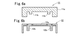
- the housing 11 shown in 6a is made of high-strength resin such as glass fiber reinforced polyamide resin (especially MXD6 nylon), and the main body portion 11a and the convex portion 11b can be integrally formed by injection molding.
- high-strength resin such as glass fiber reinforced polyamide resin (especially MXD6 nylon)
- the resin requires a thickness of at least about 1 mm in order to satisfy the required strength as a housing, and there is a drawback that there is a limit to thinning.
- the housing 12 shown in FIG. 6b is formed by punching a metal housing body 12a to form a convex portion, and then forming a resin convex portion 12b by pouring resin into physical engagement.
- the main body 12a is made of metal
- the casing 12 can be thinned to a thickness of about 0.3 mm.
- the electromagnetic wave shielding property by a metal and the insulation by a resin part can be obtained, it takes time and labor for drilling the main body part 12a, and this is a great restriction in terms of design.
- the resin convex portion 12b is formed by physical engagement with the hole formed in the metal main body portion 12a, there is a drawback that the airtightness of the engagement portion is poor and the waterproof property is poor. .
- Patent Document 2 discloses that a metal plate whose plate surface is coated with a coating resin is inserted and fixed in a cavity of an injection mold, and is melted on the coating resin surface of the metal plate. It has been proposed to form an injection-molded part by injecting resin and to integrate the metal plate and the injection-molded part. In this method, a metal plate on which a resin layer a is previously formed is appropriately processed, placed in an injection mold, and a molten resin for forming a convex portion is injected and integrally molded into a coating resin. The convex portion can be formed without going through a complicated process.
- the housing thus obtained includes a metal main body and a resin layer a, has an insulating property and electromagnetic wave shielding property, and can be thinned, and the resin layer Reinforcing ribs and screwing bosses can be formed by the convex portions integrated with a.
- Patent Document 2 mentions a polyamide-based resin such as 6 nylon as the coating resin.
- this coating resin layer a is used.
- the adhesive strength of the convex portion formed by injection molding may not be sufficiently obtained. That is, in order to integrally form a convex portion with high adhesive strength by injection molding of a molten resin to the coating resin layer, the coating resin is appropriately melted by the heat of the molten resin at the time of injection molding. After being in a compatible state, it is necessary to cool and solidify, and for that purpose, it is necessary to sufficiently control the crystallinity of the coating resin, and further the melting point. It has not been examined.
- the coated resin layer has high adhesion to the molten resin to be injected, excellent press workability, heat resistance that can withstand the mold temperature (80 to 120 ° C), and does not cause deformation due to injection pressure. Although material strength etc. are calculated
- Patent Document 2 a combination of a polyester resin as a coating resin and a mixture of polycarbonate (PC) and ABS resin as a resin for forming a convex portion is preferable in terms of compatibility.
- PC polycarbonate
- ABS resin ABS resin
- the present invention has been made in view of the above-described conventional situation, and is a resin / metal composite laminate in which a resin layer a is laminated on the surface of a metal plate, and is made of a synthetic resin on the resin layer a.
- a resin / metal composite laminate that can be formed integrally with high adhesive strength by injection molding, and a convex made of synthetic resin on the resin layer a of this resin / metal composite laminate. It is an object of the present invention to provide a resin / metal composite injection-molded article that is suitably formed as a constituent material of various structural materials, particularly housings of OA equipment and electronic equipment.
- the inventors of the present invention have made a polyamide resin layer having a crystallization index adjusted to a predetermined range, or laminated on the polyamide resin layer as an intermediate layer. It has been found that a desired convex portion can be integrally formed with high adhesive strength if the resin layer is mainly composed of a mixed resin of polycarbonate resin and polyester resin.
- the present invention has been achieved on the basis of such knowledge, and the gist thereof is as follows.
- the resin / metal composite laminate of the present invention (first aspect) is a resin / metal composite laminate comprising a metal plate and a resin layer mainly composed of a polyamide-based resin laminated on at least one surface of the metal plate.
- a crystallization index of the resin layer a calculated from the following formula (I) is 0.40 to 0.80.
- H m1 and H c1 were heated at a heating rate of 10 ° C./min in a temperature range of 30 to 300 ° C. by a differential scanning calorimeter (DSC), respectively.
- the amount of heat of crystal melting (first heat of crystal melting) and the amount of heat of crystallization (first heat of heat of crystallization) measured at the time, H m2 was then allowed to cool to 30 ° C., and then again the resin layer a Is the heat of crystal fusion (second heat of crystal fusion) measured when the temperature is raised at a rate of temperature rise of 10 ° C./min in the temperature range of 30 to 300 ° C.)
- the resin / metal composite laminate of the second aspect is characterized in that, in the resin / metal composite laminate of the first aspect, the polyamide resin contained in the resin layer a is 6 nylon.
- the resin / metal composite laminate of the third aspect is the resin / metal composite laminate of the first or second aspect, wherein the resin layer a has a thickness of 5 to 100 ⁇ m and the metal plate has a thickness of 0. 0.03 to 3.0 mm.
- the resin / metal composite laminate of the fourth aspect is the resin / metal composite laminate of any one of the first to third aspects, wherein a mixed resin of a polycarbonate resin and a polyester resin is formed on the resin layer a. It further has the 2nd resin layer b which has the main ingredients.
- the resin / metal composite laminate of the sixth aspect is the resin / metal composite laminate of the fourth or fifth aspect, wherein the polyester resin contained in the resin layer b is polybutylene terephthalate. ⁇ Metal composite laminate.
- the resin / metal composite laminate of the seventh aspect is characterized in that it is used for in-mold molding in any of the resin / metal composite laminate of the fourth to sixth aspects.
- the resin / metal composite laminate according to the eighth aspect is the resin / metal composite laminate according to any one of the first to third aspects, wherein a convex portion made of a synthetic resin is integrally formed on the resin layer a by injection molding. It is a resin-metal composite laminate material for forming into.
- the resin / metal composite laminate according to the ninth aspect is the resin / metal composite laminate according to any one of the fourth to seventh aspects, wherein a convex portion made of a synthetic resin is integrally formed on the resin layer b by injection molding. It is a resin-metal composite laminate material for forming into.
- the resin / metal composite laminate of the tenth aspect constitutes the resin layer a, the resin layer b, or the resin layer a and the resin layer b in the resin / metal composite laminate of the eighth aspect or the ninth aspect.
- the melting point of the resin is characterized by being 10 to 60 ° C. lower than the melting point of the synthetic resin constituting the convex portion.
- the resin / metal composite laminate of the eleventh aspect is characterized in that, in the resin / metal composite laminate of the tenth aspect, the synthetic resin constituting the convex portion is MXD6 nylon.
- the resin / metal composite laminate of the twelfth aspect is characterized in that, in the resin / metal composite laminate of the tenth aspect, the synthetic resin constituting the convex portion is a polycarbonate resin.
- the resin / metal composite laminate of the thirteenth aspect is the resin / metal composite laminate of any of the first to twelfth aspects, wherein the resin layer a or the resin layer a and the resin layer b of the metal plate are formed.
- the surface opposite to the formed surface is anodized.
- the resin / metal composite laminate of the fourteenth aspect is the resin / metal composite laminate of any one of the first to thirteenth aspects, wherein the resin layer a or the resin layer a and the resin layer b of the metal plate are formed.
- the coating film layer and the resin coating layer are provided in this order on the surface opposite to the formed surface.
- the resin / metal composite injection molded product of the present invention is a synthetic resin on the resin layer a or the resin layer b of the resin / metal composite laminate of the present invention (any of the first to 14th aspects). By projecting the molten resin, a convex portion made of the synthetic resin is integrally formed.
- the casing for OA equipment or electronic equipment of the present invention (16th aspect) includes the resin / metal composite injection molded body of the present invention (15th aspect).
- the casing for OA equipment or electronic equipment according to the seventeenth aspect is a casing for a mobile phone in the casing for OA equipment or electronic equipment according to the sixteenth aspect.
- the method for producing a resin / metal composite laminate of the present invention (18th aspect) is a method for producing the resin / metal composite laminate of the present invention (any of the first to 14th aspects), wherein the metal It has the lamination process of welding a resin film to a board, It is characterized by the above-mentioned.
- the method for producing a resin / metal composite injection molded article of the present invention is a method for producing the resin / metal composite injection molded article of the present invention (15th aspect), wherein the resin / metal composite laminate It has the process of inject
- the resin constituting the resin layer a of the resin / metal composite laminate of the present invention is mainly composed of a polyamide-based resin, and its crystallization index is controlled within a specific range.
- the resin of the resin layer a is appropriately melted by the heat of the molten resin, and is cooled and hardened in a sufficiently compatible state with the injected molten resin, so that the resin layer a has a high adhesive strength.
- the convex part of a synthetic resin can be formed.
- the resin / metal composite laminate is formed by laminating a resin layer b mainly composed of a mixed resin of a polycarbonate resin and a polyester resin on the resin layer a, a resin to be injection-molded, for example, It has high adhesiveness to polycarbonate resin and is flexible, so it has excellent press workability, and also has heat resistance that can withstand the mold temperature (80 to 120 ° C).
- the resin-metal composite laminate material of the present invention is formed by integrally molding a synthetic resin convex portion by injection molding a synthetic resin molten resin on the resin layer a or the resin layer b of the present invention. Since the resin / metal composite injection molded body is provided with a metal plate and a resin layer, it has electromagnetic wave shielding properties and insulation, and the metal plate is used as a base material, so that it can be thinned with sufficient strength. Since the convex portions that serve as reinforcing ribs, screw bosses, and the like are firmly formed integrally with the resin layer, various structural materials, especially OA equipment and electronic equipment casings, especially cell phones It is suitable as a housing and is effective in improving its thinness and size.
- the resin / metal composite laminate of the present invention comprises a metal plate, a resin layer a mainly composed of a polyamide-based resin laminated on at least one surface of the metal plate, or a resin layer a and the resin layer a. Further, a resin / metal composite laminate having a resin layer b mainly composed of a mixed resin of a polycarbonate-based resin and a polyester-based resin, wherein the resin layer a is calculated by the following formula (I): The crystallinity index is 0.40 to 0.80.
- H m1 and H c1 were heated at a heating rate of 10 ° C./min in a temperature range of 30 to 300 ° C. by a differential scanning calorimeter (DSC), respectively.
- the amount of heat of crystal melting (first heat of crystal melting) and the amount of heat of crystallization (first heat of heat of crystallization) measured at the time, H m2 was then allowed to cool to 30 ° C., and then again the resin layer a Is the heat of crystal fusion (second heat of crystal fusion) measured when the temperature is raised at a rate of temperature rise of 10 ° C./min in the temperature range of 30 to 300 ° C.)
- Fig. 1a and 1b are cross-sectional views showing an example of an embodiment of the resin / metal composite laminate of the present invention.
- the resin / metal composite laminate 1a, 1b has a primer layer 1C on one surface of a metal plate 1A.
- a resin layer 1B is formed through the.
- FIG. In the resin / metal composite laminate 1a of 1a the resin layer 1B has a single layer structure of the resin layer a (indicated by reference numeral “1B-a” in FIG. 1a).
- the reference numeral “1B-b” represents a two-layer structure having a surface layer.
- Metal plate Specific examples of the metal plate according to the present invention include pure aluminum plate, aluminum alloy plate, stainless steel plate, steel plate, pure titanium plate, titanium alloy plate, magnesium alloy plate, nickel, zinc, copper and other single layer plating.
- electrolytic treatment in a dichromic acid solution to form a monolayer film composed of chromium hydrated oxide on these steel sheets and plated steel sheets, or a two-layer film composed of chromium hydrated oxide on the upper layer and metallic chromium on the lower layer
- Various surface-treated steel plates, stainless steel plates, aluminum alloy plates, and other chemical conversion treatments that form single-layer coatings composed of chromium hydrated oxides. Examples thereof include immersion chromic acid treatment, phosphoric acid chromic acid treatment, an aluminum plate, an aluminum alloy plate, copper, a copper alloy and the like which are subjected to etching treatment with an alkaline solution or an acid solution, an anodic oxidation treatment, and the like.
- a stainless steel plate such as SUS304 or a surface-treated plate thereof, such as a plated steel plate, is preferable because of its high strength and excellent corrosion resistance, and since it is lightweight, an aluminum plate, an aluminum alloy plate, or a surface treatment thereof.
- a plate is preferred.
- the thickness of the metal plate is appropriately determined according to the intended use of the resin / metal composite laminate and the resin / metal composite injection molded body using the resin / metal composite laminate. Usually, it is 0.03 to 3.0 mm, particularly 0.1 to 2.0 mm. In particular, in applications where thinning is required, such as mobile phone casings, the thickness of the metal plate is preferably about 0.1 to 1.0 mm, and the metal plate is a stainless steel plate such as SUS304. In some cases, the thickness is preferably 0.1 to 0.6 mm, and in the case of an aluminum or aluminum alloy plate, it is preferably about 0.3 to 1.0 mm.
- the thickness of the metal plate is too thin, the required strength cannot be obtained, and deformation due to the resin pressure during injection molding occurs, or after molding, the metal plate deforms due to resin shrinkage, which is too thick. And thinning cannot be achieved.
- the primer layer 1C in 1a and 1b is not necessarily required, but it is preferable to interpose various primers and adhesive layers for the purpose of improving the adhesion between the metal plate 1A and the resin layer 1B.
- primers and adhesives conventionally known coupling agents such as aluminum, titanium and silane, acrylic resin adhesives, urethane resin adhesives, epoxy resin adhesives, polyester resin adhesives, etc.
- 1 type, or 2 or more types, such as an adhesive agent can be used, it is not limited to what was illustrated.
- the thickness of the primer layer and the adhesive layer is usually about 0.1 to 15 ⁇ m in order to sufficiently obtain the effect of improving the adhesion between the metal plate and the resin layer a without inhibiting the thinning.
- the resin layer a according to the present invention (resin layer 1B-a in FIG. 1a, 1b) is composed mainly of a polyamide-based resin, and has a crystallization index of 0.40 to 0.80.
- the “main component” refers to a resin that occupies 50% by mass or more, preferably 80% by mass or more, particularly preferably 95% by mass or more of the resin constituting the resin layer a.
- the polyamide resin constituting the resin layer a is produced by polycondensation reaction of 6 nylon, 11 nylon, 12 nylon, 66 nylon, 610 nylon, 612 nylon, 46 nylon, metaxylylenediamine and adipic acid. And aromatic polyamide-based resin containing 90 mol% or more of the structural unit.
- an acid-modified product of these resins with carboxylic anhydride or the like, an epoxy-modified product with glycidyl methacrylate, or the like may be used alone or as a mixture.
- Polyamide-based resin is excellent in compatibility with the resin for forming the convex part of the resin / metal composite injection molded product, which will be described later, excellent in fusibility, and excellent in workability, and at the time of bending and drawing of the resin / metal composite laminate It is preferable in that it does not easily crack and is excellent in heat resistance, and can sufficiently withstand the mold temperature (usually 100 to 160 ° C.) at the time of injection molding described later.
- the resin constituting the resin layer a may be a mixture with a resin other than the polyamide-based resin.
- specific examples of the resin other than the polyamide-based resin include polyester-based resins such as polyethylene terephthalate and polybutylene terephthalate, and olefin-based resins such as polyethylene, polypropylene, and copolymers mainly composed of ethylene.
- the resin layer a according to the present invention is formed by using only a polyamide-based resin as a resin component in terms of control of the crystallization index and compatibility with a synthetic resin constituting a convex portion, which will be described later, and fusibility. In particular, it is preferable that only 6 nylon is formed as a resin component.
- the resin layer a according to the present invention is formed by further blending a resin additive such as an adhesion-imparting agent, a lubricant, or a pigment with the above-described resin mainly composed of polyamide-based resin.
- a resin additive such as an adhesion-imparting agent, a lubricant, or a pigment with the above-described resin mainly composed of polyamide-based resin.
- Crystallization index of the resin layer a according to the present invention exceeds 0.80, the meltability with heat by the injected molten resin is not sufficient at the time of injection molding described later, and the convex portions are integrated with high adhesive strength. It cannot be molded. If the crystallization index is less than 0.40, the heat resistance is inferior, which is not preferable. Therefore, the crystallization index of the resin layer a is 0.40 to 0.80, preferably 0.6 to 0.75.
- crystallization index of the resin layer a is specifically measured and calculated by the method described in the Examples section described later.
- Examples of the method for setting the crystallization index of the resin layer a in the above range include a method of selecting an appropriate polyamide-based resin and appropriately adjusting the cooling conditions after the resin layer a is formed on the metal plate as described later. It is done. In addition, there is a method in which after adding a filler or the like to the selected polyamide resin, the cooling condition is adjusted so that the crystallization index is within the above range.
- the resin constituting the resin layer a satisfies the above crystallization index and has a melting point of 10 to 60 ° C., particularly 10 to 40 ° C., especially 10 to 40 ° C., more than the melting point of a synthetic resin for forming a convex portion by injection molding described later. It is preferably 15 to 40 ° C. lower. If the melting point of the resin constituting the resin layer a is too high, the meltability with heat by the injected molten resin is not sufficient at the time of injection molding described later, and the convex portions cannot be integrally molded with high adhesive strength. . However, when the melting point is too low, the heat resistance is inferior and the temperature of the injection mold cannot be endured.
- the thickness of the resin layer a is excessively thin, the projections cannot be integrally formed with high adhesive strength in the injection molding of the projections described below, and the resin / metal composite laminate material Problems such as pinholes may occur during processing. If the thickness of the resin layer a is excessively large, the resin layer a is likely to be peeled off during processing such as bending of the resin / metal composite laminate, and the resin / metal composite laminate, as well as resin / metal composite injection molding. Inhibits thinning of the body.
- the thickness of the resin layer a is determined by whether or not a resin layer b described later is laminated on the resin layer a, the use of the resin / metal composite laminate and the resin / metal composite injection molded body, and the resin layer a. Although it varies depending on the shape and structure of the protrusions formed on the top, it is preferably 5 to 100 ⁇ m. Especially when the resin layer b is not formed on the resin layer a, the thickness of the resin layer a is 15 to 100 ⁇ m. Preferably, the thickness is 20 to 50 ⁇ m. When the resin layer b is formed on the resin layer a, the thickness of the resin layer a is preferably 5 to 50 ⁇ m, particularly 10 to 40 ⁇ m, particularly 10 to 30 ⁇ m.
- the resin layer b includes a mixed resin of a polycarbonate resin and a polyester resin. It can form from the resin composition which has a main component.
- a polycarbonate resin alone, there is a problem in press workability, and cracks and the like are generated after processing, but press workability is improved by using a mixed resin of a polycarbonate resin and a polyester resin.
- the polycarbonate resin is composed of carbonic acid and glycol or dihydric phenol, and is represented by the general formula: — (O—R—O—CO—) n — (R is a divalent fatty acid or aromatic group). I just need it.
- a structure in which a part or all of bisphenol A is substituted with another dihydric phenol can also be used.
- other dihydric phenols include hydroquinone, 4,4-dihydroxydiphenyl, bis (4-hydroxyphenyl) methane, and bis (4-hydroxyphenyl) alkanes such as 1-bis (4-hydroxyphenyl) ethane.
- Bis (4-hydroxyphenyl) cycloalkanes such as 1,1-bis (4-hydroxyphenyl) cyclohexane, bis (4-hydroxyphenyl) sulfide, bis (4-hydroxyphenyl) sulfone, bis (4-hydroxy Compounds such as phenyl) sulfoxide, bis (4-hydroxyphenyl) ether, alkylated bisphenols such as 2,2-bis (3-methyl-4-hydroxyphenyl) propane, 2,2-bis (3,5- Such as dibromo-4-hydroxyphenyl) propane Mention may be made of halogenated bisphenols.
- the viscosity-average molecular weight of the polycarbonate-based resin is not particularly limited, but is preferably in the range of 10,000 to 100,000, particularly 20,000 to 30,000, particularly 23,000 to 28,000.
- the melt flow rate of the polycarbonate-based resin is not particularly limited, but a melt flow rate measured at 300 ° C. under a 1.2 kg load is preferably 5 to 20 based on JISK7210.
- polycarbonate resin examples include “Iupilon” series manufactured by Mitsubishi Engineering Plastics, “Caliber” series manufactured by Sumitomo Dow, and the like.
- polycarbonate-type resin one type of polycarbonate-type resin may be used independently, and 2 or more types of polycarbonate-type resins may be mixed and used.
- polyester resin As the polyester-based resin, a resin obtained by condensation polymerization of a dicarboxylic acid component and a diol component, particularly an aromatic polyester-based resin formed by condensation polymerization of an aromatic dicarboxylic acid component and a diol component is preferable. .
- aromatic dicarboxylic acid component examples include terephthalic acid, isophthalic acid, naphthalenedicarboxylic acid, etc., but a part of terephthalic acid is substituted with “other dicarboxylic acid component”. It may be.
- the “other dicarboxylic acid component” includes oxalic acid, malonic acid, succinic acid, adipic acid, azelaic acid, sebacic acid, neopentylic acid, isophthalic acid, naphthalenedicarboxylic acid, diphenyl ether dicarboxylic acid, p-oxybenzoic acid Etc. These may be one kind or a mixture of two or more kinds, and the amount of other dicarboxylic acids to be substituted can be appropriately selected.
- diol component examples include ethylene glycol, diethylene glycol, triethylene glycol, cyclohexanedimethanol and the like, but a part of ethylene glycol may be substituted with “other diol component”.
- other diol components propylene glycol, butanediol, trimethylene glycol, tetramethylene glycol, hexamethylene glycol, diethylene glycol, neopentyl glycol, polyalkylene glycol, 1,4-cyclohexanedimethanol, glycerin
- examples include pentaerythritol, trimethylol, and methoxypolyalkylene glycol. These may be one kind or a mixture of two or more kinds, and the amount of other diols to be substituted can be appropriately selected.
- polyester resins “copolyester” containing a dicarboxylic acid component other than terephthalic acid and / or a diol component other than ethylene glycol can also be used.
- aromatic copolymer polyesters include “Novapex” series (for example, Novapex PS600) manufactured by Mitsubishi Chemical Corporation, which is a modified product of polyethylene terephthalate, and Mitsubishi Engineering, which is a modified product of polybutylene terephthalate.
- a “Novaduran” series (for example, Novaduran 5008) manufactured by Plastics may be mentioned.
- “Easter 6673” manufactured by Eastman Chemical Co. which is a polyester resin in which about 30 mol% of ethylene glycol in polyethylene terephthalate is substituted with 1,4-cyclohexanedimethanol, has a slightly low melt viscosity consisting of the same components.
- Easter series including “Easter GN119” can be mentioned.
- polybutylene terephthalate using butanediol as the diol component and terephthalic acid as the aromatic dicarboxylic acid component is most preferable.
- polybutylene terephthalate is a crystalline resin, it is excellent in heat resistance and strength, and particularly as a polyester resin constituting the resin layer b from the point of being completely compatible with a polycarbonate resin to become a polymer alloy.
- Specific examples of such polybutylene terephthalate products include, for example, “Juranex” series manufactured by Wintech Polymer, and “Novaduran” series manufactured by Mitsubishi Engineering Plastics.
- a mixture of polybutylene terephthalate and the above copolymerized polyester can also be used.
- the mixing ratio of the polyester resin and the polycarbonate resin constituting the resin layer b is 20:80 to 70:30, more preferably 20:80 to 60:40, particularly 30:70 to 50:50, in particular, In particular, it is preferably in the range of 35:65 to 45:55. Within the range of this mixing ratio, cracks are not generated even during press working, and the film surface is preferably not melted during injection molding.
- the resin constituting the resin layer b has a melting point that is 10 to 60 ° C., particularly 10 to 40 ° C., particularly 15 to 40 ° C. lower than the melting point of a synthetic resin for forming a convex portion by injection molding described later. It is preferable. If the melting point of the resin constituting the resin layer b is too high, the meltability with heat by the injected molten resin is not sufficient at the time of injection molding described later, and the convex portions cannot be integrally molded with high adhesive strength. . However, when the melting point is too low, the heat resistance is inferior and the temperature of the injection mold cannot be endured.
- the melting point of the resin layer a is not necessarily limited to the one lower than the melting point of the synthetic resin for forming the convex portion by injection molding described later. If the melting point of the layer a is too low, the resin layer a may be peeled off from the metal plate due to the heat of the molding resin and mold during injection molding, which is not preferable. From this point of view, the melting point of the resin layer a is also 10 to 60 ° C., particularly 10 to 40 ° C., especially 15 to 40 ° C. lower than the melting point of the synthetic resin for forming the convex portion by injection molding described later. It is preferable.
- the thickness of the resin layer b is preferably 10 to 200 ⁇ m. If the thickness of the resin layer b is less than 10 ⁇ m, pinholes may be produced when drawing, bending, etc., and adhesion to the injection molded part may not be improved. On the other hand, if it exceeds 200 ⁇ m, it may become too thick and press workability may be lowered, which is disadvantageous economically.
- the resin / metal composite laminate of the present invention in which such a resin layer b is laminated on the resin layer a has high adhesiveness with the molten resin injected by the resin layer b on the surface and is excellent in press workability. Furthermore, since it has excellent features such as heat resistance that can withstand the mold temperature (80-120 ° C) and material strength that does not cause deformation due to injection pressure, the molten resin is injected onto the surface by in-mold molding. It is suitable as a resin / metal composite laminate for fixing and integrating an injection molded product.
- the resin / metal composite laminate of the present invention is the resin layer forming surface of the metal plate, that is, the surface on which the resin layer a or the resin layer a and the resin layer b are formed.
- the surface on the opposite side may be anodized.
- Anodizing is performed by performing surface finishing, degreasing, anodizing, dyeing, sealing treatment, etc. on the resin-metal composite laminate with the resin layer a or resin layer a and resin layer b formed on one side. This is a processing method of forming an alumite layer on the aluminum surface.
- surface finishing examples include physical finishing such as mirror finishing by buffing, mat finishing by blasting, and hairline finishing. Further, mat finishing using an aqueous ammonium fluoride solution, phosphoric acid-sulfuric acid aqueous solution, or It can also be performed by chemical polishing using a phosphoric acid-nitric acid aqueous solution, electrolytic polishing using a phosphoric acid aqueous solution, or the like.
- degreasing examples include degreasing with sulfuric acid and electrolytic degreasing in an aqueous sodium hydroxide solution.
- a sulfuric acid method for the anodization, a sulfuric acid method, an oxalic acid method, a phosphoric acid method, or the like can be employed. Specific conditions will be described.
- an electrode is connected to a resin / metal composite laminate, and immersed in a 10 to 30 mass% sulfuric acid aqueous solution adjusted to 15 to 25 ° C., and a current density of 50 to 300 A /
- an aluminum oxide layer can be formed on the surface of the metal plate.
- the thickness of the aluminum oxide layer to be produced is not particularly limited, but if it is too thin, sufficient performance will not be exhibited. Conversely, if it is too thick, the treatment time will be long, which is not economical.
- the aluminum oxide layer has a thickness in the range of 1 to 20 ⁇ m.
- the alumite layer can be dyed before the sealing treatment.
- the dyeing method include a method of dyeing using an organic dye, a method of dyeing by dipping in a dyeing solution containing a metal salt, and the like.
- Examples of the sealing treatment include a method of exposing to water vapor and a method of immersing in boiling water, whereby the alumite layer becomes a hydrate and the corrosion resistance can be greatly improved.
- Anodizing may be performed at any stage before or after injection molding, but in order to avoid appearance defects due to the metal surface coming into contact with the mold during injection molding, anodizing is performed after injection molding. Is preferably performed.
- the resin / metal composite laminate of the present invention decorates the resin layer-forming surface of the metal plate, that is, the surface opposite to the surface on which the resin layer a or the resin layer a and the resin layer b are formed, by painting.
- the coating film layer and the resin coating layer are provided in this order on the surface.
- a coating film layer is laminated on a metal plate, it is possible to use a paint conventionally used for polycarbonate, MXD6 nylon, or the like.
- the drying temperature can be suppressed to about 60 to 80 ° C., and the molding resin is not softened or deformed at the time of drying, and the adhesion force of the paint is greatly improved. be able to.
- the thickness of the coating film layer is preferably about 5 to 50 ⁇ m. If the thickness of the coating film layer is in the range of 5 to 50 ⁇ m or more, adhesive strength with the paint can be expressed, which is economically advantageous.
- paints that can be used in the resin coating layer include urethane resins, acrylic resins, and polyamide resins, which can be applied by any method such as spraying.
- a hard coat layer may be provided on the outermost layer of the resin coating layer.
- the thickness of the resin coating layer is not particularly limited, and the thickness is appropriately determined according to the purpose.
- the resin constituting the coating film layer is matched with the resin forming the convex portion, for example, the same resin is selected as the resin constituting the coating film layer and the resin forming the convex portion
- the same resin is selected as the resin constituting the coating film layer and the resin forming the convex portion
- a convex portion made of MXD6 nylon is injection-molded on the resin layer a
- a convex portion made of polycarbonate is injection-molded on the resin layer b.
- a resin layer having a high adhesiveness with respect to both resin layers may be formed as an adhesive layer between the resin layer a and the resin layer b.
- an adhesive layer include an adhesive layer made of a polyester resin, an epoxy resin, a urethane resin, and the like, and an adhesive layer made of a polyester resin is preferable.
- Metal plate and resin layer that is, resin layer a, or resin layer a and resin layer b constituting the resin / metal composite laminate of the present invention, a primer layer or an adhesive layer provided as necessary, and other configurations
- the preferred thickness of the layer is as described above, and the total thickness of the resin / metal composite laminate of the present invention varies depending on the application, but is usually 0.1 to 3.0 mm, particularly 0.1 to 3.0 mm. It is preferably about 0.1 to 1.0 mm in an application where the thickness is required to be 2.0 mm, such as a casing of a mobile phone.
- the resin / metal composite laminate of the present invention has a resin layer a mainly composed of a polyamide-based resin satisfying the crystallization index, or the resin layer a and the resin layer b, on at least one surface of the metal plate. It is manufactured by forming.
- a method of forming the resin layer a on the metal plate a method of forming a laminated layer by extruding a molten resin of the resin for forming the resin layer a on the surface of the metal plate, a pre-molded film of the resin for forming the resin layer a
- examples include a method of laminating a metal plate.
- a molten resin for forming the resin layer a and a molten resin for forming the resin layer b are coextruded together with a film on the surface of the metal plate.
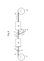
- Fig. 3 is a schematic diagram showing a process of producing a resin / metal composite laminate of the present invention by laminating a resin film on a metal plate, and the metal plate 21 is moved from the wound body 21 of the metal plate to a pair of rollers. 23, 23 and sent in the direction of the arrow, passed through the heating furnace 24 and heated, and then sent out from the wound body 25 of the resin film (resin film for forming the resin layer a or resin layer a A laminated film of a resin for forming resin and a resin for forming resin layer b) is laminated and pressed between a pair of rollers 27, 27, and further reheated in a reheating furnace 28 to make the resin film 26 a metal plate.
- the resin / metal composite laminated material 29 is fused and integrated with 22, and is wound around the wound body 30.
- the metal plate may have a primer layer formed in advance, or the primer layer may be formed on the metal plate sent out in the resin film laminating process.
- the resin film may be subjected to a surface treatment such as a corona discharge treatment for the purpose of improving the adhesion with the metal plate.
- the crystal of the resin layer a formed is controlled by controlling the reheating conditions (heating temperature and heating time (line speed) in the reheating furnace 28) after the resin film is fused.
- the conversion index can be adjusted. That is, when the reheating temperature is increased and the reheating time is shortened, a resin layer a having a small crystallization index is formed. Conversely, by decreasing the reheating temperature and / or increasing the reheating time, Since a large resin layer a is formed, by controlling this reheating condition, the resin layer a having a crystallization index of 0.40 to 0.80 is formed to obtain the resin / metal composite laminate of the present invention. .
- the heating conditions for laminating the resin film on the metal plate vary depending on the type of resin constituting the resin layer (resin layer a, or resin layer a and resin layer b), but usually the metal plate
- the heating temperature (heating temperature of the heating furnace 24) is 300 to 500 ° C.
- the reheating temperature after resin film fusion is 250 to 450 ° C.
- the reheating time inside the reheating furnace 28
- the time required for the laminate to pass is preferably about 3 to 10 seconds.
- the resin / metal composite injection molded article of the present invention is obtained by injection molding a molten resin of synthetic resin on the resin layer (resin layer a or resin layer b) of the resin / metal composite laminate of the present invention as described above.
- the convex portion made of the synthetic resin is integrally formed.
- Fig. 2 is a cross-sectional view showing an example of the resin / metal composite injection molded article of the present invention.
- This resin / metal composite injection molded article 2 has a resin layer (resin layer a or resin) on one surface of the metal plate 1A.
- the convex portion 3 made of synthetic resin is integrally molded by injection molding.
- the synthetic resin for forming the convex portions by injection molding is not particularly limited, and is a styrene resin such as polystyrene, ABS resin and MBS resin, an acrylic resin such as polymethyl methacrylate, a polyester resin, and a polyolefin. Resin, polyamide resin, polycarbonate, polyphenylene oxide, and a mixture of these resins.
- MXD6 nylon a crystal obtained from metaxylylenediamine (MXDA) and adipic acid
- MXDA metaxylylenediamine
- the resin layer on the metal plate is composed of the resin layer a and the resin layer b and the surface layer is the resin layer b
- the resin layer b is excellent in compatibility with the polycarbonate resin, ABS resin.
- a mixture of a polycarbonate resin and one or more of the above resins is preferable, and a polycarbonate resin is particularly preferable.
- the convex forming synthetic resin is usually different from the resin of the resin layer of the resin / metal composite laminate.
- this convex part is not limited to the above-mentioned reinforcing rib and screwing boss, and is formed as a partition plate, an insulating plate in the housing, a protective wall of a member in the housing, a surrounding member, or the like.
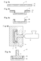
- FIG. 4a to 4e An example of a method for producing the resin / metal composite injection molded product of the present invention using the resin / metal composite laminate of the present invention is shown in FIG. 4a to 4e, the method for producing the resin / metal composite injection molded product of the present invention is described in FIG. The method is not limited to the methods shown in 4a to 4e.
- the resin / metal composite laminate 1 (primer layer 1C) of the present invention in which a metal plate 1A and a resin layer (resin layer a or resin layer a and resin layer b) 1B are laminated may be provided. ) Is cut into an appropriate size (FIG. 4a), and thereafter, drawing, bending, and punching are performed as necessary to obtain a flat plate shape, an L-shaped section, a U-shaped section, etc. (Fig. 4b, 4c).
- the molded resin / metal composite laminate 1 is placed in the cavity of the injection mold 4, and the molten resin 6 of the convex forming synthetic resin is poured from the injection molding machine 5 toward the resin layer 1 ⁇ / b> B. (FIG. 4d). Thereafter, the molded body is taken out from the mold, and the resin / metal composite injection molded body 2 of the present invention in which the convex portion 3 of the synthetic resin is formed on the surface of the resin layer 1B of the resin / metal composite laminate 1 is obtained (FIG. 4e). ).
- the resin layer a of the resin / metal composite laminate of the present invention has a crystallization index within an appropriate range, so that it is quickly melted and injected by the heat of the injected molten resin. Since the resin is compatible with the resin and fused, the projection formed by injection molding is firmly bonded and integrated with the resin layer a.
- the resin layer b when the resin layer b is provided on the resin layer a, the compatibility between the resin layer b and a polycarbonate resin, ABS resin, or a mixture of the polycarbonate resin and one or more of the above resins is used. Therefore, the convex portion formed by injection molding is firmly bonded and integrated with the resin layer b. Furthermore, the metal press suitability can be improved by providing the resin layer a having good workability between the metal plate and the metal plate.
- the injection molding conditions vary depending on the type of the convex forming resin, but when MXD6 nylon (melting point: about 240 to 245 ° C.) is used as the convex forming synthetic resin, Molten resin temperature: 270-300 ° C Injection mold temperature: 100-160 ° C It is preferable to perform injection molding.
- Molten resin temperature 270-300 ° C Injection mold temperature: 60-120 ° C It is preferable to perform injection molding.
- the resin / metal composite injection molded article of the present invention thus obtained may be further subjected to a surface treatment such as painting or plating on the surface opposite to the resin layer forming surface of the metal plate, if necessary.
- the resin / metal composite laminate of the present invention is a housing for OA equipment such as personal computers, desktop computers, various printing machines, various copying machines, telephones, electronic dictionaries / dictionaries, acoustic equipment, televisions, radios, and other electronic equipment. It is useful for body (housing) and parts, and is suitably used as a casing of a mobile phone taking advantage of its features of being particularly thin and having convex portions such as ribs and screw bosses.
- Examples 1 to 4 A bisphenol A type epoxy resin was applied to one side of a stainless steel plate (SUS304 1 / 2H 0.3 mm thick), and then a primer layer having a thickness of 1 ⁇ m was formed. Then, FIG. By the method shown in FIG. 3, a 6-nylon film (Mitsubishi Resin Co., Ltd., melting point: 220 ° C.) was laminated on the primer layer forming surface of this stainless steel plate to obtain a resin / metal composite laminate.
- a 6-nylon film Mitsubishi Resin Co., Ltd., melting point: 220 ° C.
- the heating temperature in the heating furnace 24 at the time of lamination is 350 ° C.
- the reheating temperature, the cooling method, and the reheating time in the reheating furnace 28 are as shown in Table 1, so that the resin layer formed in each example
- the degree of crystallinity was changed.
- the thickness of the formed resin layer (resin layer a) is 25 ⁇ m.
- samples were prepared under the same conditions as in Example 1.
- Example 3 was nickel-plated stainless steel (SUS304 1 / 2H 0.3 mm thickness), and Example 4 was aluminum. Each was changed to an alloy (A5182 H18 0.3 mm thickness).
- the resin / metal composite laminate is heated using a differential scanning calorimeter (DSC) manufactured by PerkinElmer, Inc. at a temperature rising rate of 10 ° C./min in the temperature range of 30 to 300 ° C., and the heat of crystal melting at this time (First crystallization heat of generation H m1 ) and crystallization exotherm (first crystallization exotherm H c1 ) were measured, then allowed to cool to 30 ° C., and then heated again in the temperature range of 30 to 300 ° C.
- DSC differential scanning calorimeter
- each resin / metal composite laminate was placed in an injection mold, and molten resin (resin temperature) of MXD6 nylon (manufactured by Mitsubishi Engineering Plastics Co., Ltd., “Lenny (registered trademark) NXG5050, melting point: 243 ° C.)” 275 ° C), injection molding is performed at a mold temperature of 160 ° C, and a cylindrical convex portion having a radius of 3.425 mm and a height of 15 mm is integrally formed on the resin layer surface of the resin / metal composite laminate. Samples were manufactured.
- the obtained tensile test sample was subjected to a tensile test by the following method, and the results are shown in Table 2.
- Example 2 The stainless steel plate used in Example 1 was heated to 100 ° C., and a commercially available nitrile butadiene rubber thermocompression bonding tape (manufactured by Tesa Tape Co., Ltd., softening point 100 ° C.) was fused to form a 38 ⁇ m thick resin layer. A resin / metal composite laminate was obtained. Using this resin / metal composite laminate, a sample for a tensile test was produced in the same manner as in Example 1. The tensile test was performed in the same manner, and the results are shown in Table 2. In Table 2, the stickiness of the resin (resin of the resin layer of the resin / metal composite laminate) on the injection mold at the time of injection molding in each example is also shown.
- the convex portion made of MXD6 nylon is formed by injection molding. It can be seen that can be integrally molded with high adhesive strength.
- the melting point of the resin layer a is too high compared to the melting point of the molten resin to be injection-molded, and the resin layer a is not sufficiently melted at the time of injection molding. Although there is nothing, the adhesive strength of the convex part is low.
- the melting point (softening point) of the resin layer a is too low compared to the melting point of the molten resin to be injection-molded, and the adhesive strength of the convex portion is higher than that of Comparative Examples 1 to 3, but is not sufficient.
- PC polycarbonate resin
- PBT polybutylene terephthalate
- phenol / tetrachloroethylene 50/50 (volume ratio) solution, intrinsic viscosity 1.2448 at 30 ° C.
- Polyester adhesive on 6 nylon film as resin layer a (thickness: 20 ⁇ m, melting point: 220 ° C., crystallization index: 0.40 to 0.80, “Diamilon” manufactured by Mitsubishi Plastics, Inc.) 6 g / m 2 of an adhesive containing 100 parts by mass and 12.5 parts by mass of an isocyanate cross-linking agent was applied and dried by heating at 60 ° C. for 30 seconds in a drying furnace. The resin layer b-forming film was laminated with a nip roll heated to 5 ° C. and cured in an oven at 60 ° C. for 5 days to obtain a laminated film.
- Bisphenol A-type epoxy resin was applied to one side of a stainless steel plate (SUS304, 1 / 2H, 0.3 mm thickness) to form a primer layer having a thickness of 1 ⁇ m.
- the laminate film is welded to a stainless steel plate heated to 300 ° C. so that the 6 nylon film side is the stainless steel plate side, and a resin / metal having a “resin layer / adhesive / 6 nylon / epoxy / SUS” configuration
- a composite laminate (evaluation sample) was obtained.
- the mold temperature was set to 80 ° C., 100 ° C. or 120 ° C., and the heat-melted polycarbonate resin was injection molded onto the resin layer of the evaluation sample (injection shape: cylindrical shape with a radius of 3.425 mm). It was visually observed whether there was any change in appearance on the surface and inside, and evaluated according to the following criteria.
- FIG. 5a cuts 32 are made on the surface of the sample 31 (at intervals of 5 mm), and then FIG. 5b, push the punch 33 having a spherical tip into the central portion of the sample 31 by 5 mm to 7 mm into the center portion of the sample 31 as shown in 5b (FIG. 5b, 34 is a die, 35 is a wrinkle presser) ), FIG. As shown in 5c, the sample 31 was observed for floating and cracking, and evaluated according to the following criteria. The results are shown in Table 5.
- Example 8 A laminate film similar to that in Example 6 was laminated on an aluminum alloy plate (A5182 H18 0.3 mm thick) in the same manner to obtain a sample.
- Example 9 After the polycarbonate resin was injection-molded on the same sample as in Example 8, it was immersed in an aqueous solution of 50% by mass phosphoric acid and 5% by mass nitric acid heated to 90 ° C. for 30 seconds, and desmutted with a 10% by mass sulfuric acid aqueous solution. After that, an electrode was attached to the sample, immersed in a 20% by mass sulfuric acid aqueous solution adjusted to 20 ° C., and energized at a current density of 150 A / m 2 to obtain a 12 ⁇ m alumite film on the metal surface. Subsequently, it was colored red with an organic dye and immersed in warm water at 95 ° C. for 2 minutes for sealing treatment.
- Example 10 After polycarbonate resin was injection-molded into the same sample as in Example 8, it was immersed in a 15% by mass aqueous solution of sodium hydroxide heated to 55 ° C. for 180 seconds, desmutted with a 10% by mass sulfuric acid aqueous solution, and then applied to the sample. An electrode was attached and immersed in a 20% by mass sulfuric acid aqueous solution adjusted to 20 ° C. and energized at a current density of 150 A / m 2 to obtain a 12 ⁇ m alumite film on the metal surface. Subsequently, it was colored in gold with an organic dye and immersed in warm water at 95 ° C. for 2 minutes for sealing treatment.
- Table 6 shows that when anodizing is performed after injection molding (Examples 9 and 10), an adhesive strength equivalent to that when not anodizing (Example 8) is obtained, and the decrease in injection adhesive strength is acceptable. Met.
Landscapes
- Engineering & Computer Science (AREA)
- Manufacturing & Machinery (AREA)
- Mechanical Engineering (AREA)
- Laminated Bodies (AREA)
- Injection Moulding Of Plastics Or The Like (AREA)
Abstract
【課題】金属板の表面に樹脂層が積層された樹脂・金属複合積層材であって、この樹脂層上に、合成樹脂よりなる凸部を射出成形により高い接着強度で一体的に形成することができる樹脂・金属複合積層材を提供する。 【解決手段】金属板と、該金属板の少なくとも一方の面に積層されたポリアミド系樹脂を主成分とする樹脂層aとを有する樹脂・金属複合積層材。この樹脂層aの結晶化指数(I)は0.40~0.80である。(Hm1、Hc1、Hm2は、DSCによる第1回結晶融解熱量、第1回結晶化発熱量、第2回結晶融解熱量)
Description
本発明は、樹脂・金属複合積層材及びその製造方法に係り、特に、金属板の少なくとも一方の面にポリアミド系樹脂を主成分とする樹脂層aが積層された樹脂・金属複合積層材或いはこの樹脂層a上に更にポリカーボネート系樹脂とポリエステル系樹脂との混合樹脂を主成分とする樹脂層bが積層された樹脂・金属複合積層材であって、この樹脂層a又は樹脂層b上にインモールド成形やインサート成形等の射出成形により合成樹脂よりなる凸部を一体的に形成して、各種の構造材、特に、OA機器や電子機器の筐体の構成材料として好適な樹脂・金属複合射出成形体を製造するための基材として用いられる樹脂・金属複合積層材及びその製造方法に関する。
本発明はまた、この樹脂・金属複合積層材の樹脂層a又は樹脂層b上に合成樹脂よりなる凸部を射出成形により一体的に形成してなる樹脂・金属複合射出成形体及びその製造方法に関する。
本発明はまた、この樹脂・金属複合射出成形体よりなるOA機器用又は電子機器用の筐体に関する。
本発明はまた、この樹脂・金属複合積層材の樹脂層a又は樹脂層b上に合成樹脂よりなる凸部を射出成形により一体的に形成してなる樹脂・金属複合射出成形体及びその製造方法に関する。
本発明はまた、この樹脂・金属複合射出成形体よりなるOA機器用又は電子機器用の筐体に関する。
OA機器、電子機器の筐体(ハウジング)、特に、携帯電話やノートパソコンのような携帯機器の筐体は、近年、益々薄肉小型化が望まれている。また、これらの筐体には、絶縁性、更には電磁波シールド性も要求されると共に、その内面側に補強用リブやネジ止め用ボスなどの凸部を形成する必要があることから、薄肉小型化を図った上で、筐体本体に対してこれらの凸部を強固に一体成形するための研究開発が進められている(特許文献1参照)。
従来、携帯電話の筐体には、Fig.6a,6bに示す構成のものが採用されている。
Fig.6aに示す筐体11は、ガラス繊維補強ポリアミド系樹脂(特にMXD6ナイロン)のような高強度樹脂製のものであり、本体部11aと凸部11bとを射出成形により一体成形することができるという利点を有する反面、高強度樹脂であっても、樹脂では筐体としての必要強度を満たすためには、少なくとも1mm程度の厚みが必要であり、薄肉化にも限界があるという欠点があった。
Fig.6bに示す筐体12は、金属製の筐体本体12aに凸部形成のための孔明け加工を施し、その後、樹脂を流し込んで物理的な係合により、樹脂製の凸部12bを形成したものである。この筐体12は、本体部12aが金属製であることから、厚みとして0.3mm程度にまで薄肉化することができる。また、金属による電磁波シールド性と、樹脂部による絶縁性も得ることができるが、本体部12aの孔明け加工に手間を要し、デザインの点でも大きな制約となる。さらに、樹脂製凸部12bを金属製の本体部12aに形成した孔部に対する物理的な係合で形成しているため、この係合部の気密性が悪く、防水性が悪いという欠点がある。
このような従来の筐体に対して、特許文献2には、板面を被覆樹脂で被覆した金属板を射出成形金型のキャビティ内に挿入・固定し、この金属板の被覆樹脂面に溶融樹脂を射出して射出成形部分を形成し、金属板と射出成形部分とを一体化することが提案されている。
この方法であれば、予め樹脂層aを形成した金属板を適宜加工したものを、射出成形金型内に配置し、凸部形成用の溶融樹脂を射出して被覆樹脂に一体成形することにより、複雑な工程を経ることなく、凸部を形成することができる。
また、このようにして得られる筐体は、金属製の本体部と樹脂層aとを備えるものであり、絶縁性、電磁波シールド性を有し、また、薄肉化も可能であると共に、樹脂層aに一体化された凸部で補強用リブやネジ止用ボスを形成することができる。
この方法であれば、予め樹脂層aを形成した金属板を適宜加工したものを、射出成形金型内に配置し、凸部形成用の溶融樹脂を射出して被覆樹脂に一体成形することにより、複雑な工程を経ることなく、凸部を形成することができる。
また、このようにして得られる筐体は、金属製の本体部と樹脂層aとを備えるものであり、絶縁性、電磁波シールド性を有し、また、薄肉化も可能であると共に、樹脂層aに一体化された凸部で補強用リブやネジ止用ボスを形成することができる。
特許文献2には、被覆樹脂として、6ナイロン等のポリアミド系樹脂が挙げられているが、その結晶化度、更には融点についての検討がなされていないために、この被覆樹脂層aに対して射出成形により形成した凸部の接着強度が十分に得られない場合があるという不具合がある。
即ち、被覆樹脂層に対して、溶融樹脂の射出成形により、高い接着強度の凸部を一体成形するためには、射出成形時に、溶融樹脂の熱で被覆樹脂が適度に溶融し、溶融樹脂と相溶状態となった後、冷却固化される必要があり、そのためには、被覆樹脂の結晶化度、更には融点を十分に制御することが必要となるが、特許文献2では、このような検討がなされていない。
更には、被覆樹脂層には、射出する溶融樹脂との接着性が高いと共に、プレス加工性に優れ、金型温度(80~120℃)に耐える耐熱性、また、射出圧力によって変形を起こさない材料強度などが求められるが、特許文献2では、このような検討がなされていない。
即ち、被覆樹脂層に対して、溶融樹脂の射出成形により、高い接着強度の凸部を一体成形するためには、射出成形時に、溶融樹脂の熱で被覆樹脂が適度に溶融し、溶融樹脂と相溶状態となった後、冷却固化される必要があり、そのためには、被覆樹脂の結晶化度、更には融点を十分に制御することが必要となるが、特許文献2では、このような検討がなされていない。
更には、被覆樹脂層には、射出する溶融樹脂との接着性が高いと共に、プレス加工性に優れ、金型温度(80~120℃)に耐える耐熱性、また、射出圧力によって変形を起こさない材料強度などが求められるが、特許文献2では、このような検討がなされていない。
なお、特許文献2では、被覆樹脂はポリエステル系樹脂、凸部形成用樹脂はポリカーボネート(PC)とABS樹脂との混合物とする組み合わせが相溶性の面で好ましいとされているが、PC/ABS樹脂では、補強用リブ、ネジ止用ボスとしての必要強度を十分に満たせない場合もあることから、現在、高強度エンジニアリングプラスチックとして注目されているMXD6ナイロンで凸部を形成すること、また、この場合において、高い接着強度を実現し得る被覆樹脂層aを選択することが要求される。
本発明は上記従来の実状に鑑みてなされたものであって、金属板の表面に樹脂層aが積層された樹脂・金属複合積層材であって、この樹脂層a上に、合成樹脂よりなる凸部を射出成形により高い接着強度で一体的に形成することができる樹脂・金属複合積層材と、この樹脂・金属複合積層材の樹脂層a上に合成樹脂よりなる凸部を射出成形により一体的に形成してなり、各種構造材、特に、OA機器や電子機器の筐体の構成材料として好適な樹脂・金属複合射出成形体を提供することを課題とする。
本発明者らは上記課題を解決すべく鋭意検討した結果、結晶化指数が所定の範囲に調整されたポリアミド系樹脂層、或いは、このようなポリアミド系樹脂層を中間層としてその上に積層形成されたポリカーボネート系樹脂とポリエステル系樹脂との混合樹脂を主成分とする樹脂層であれば、所望の凸部を高い接着強度で一体成形することができることを見出した。
本発明はこのような知見に基いて達成されたものであり、以下を要旨とする。
本発明(第1態様)の樹脂・金属複合積層材は、金属板と、該金属板の少なくとも一方の面に積層されたポリアミド系樹脂を主成分とする樹脂層とを有する樹脂・金属複合積層材であって、下記式(I)で算出される、前記樹脂層aの結晶化指数が0.40~0.80であることを特徴とする。

(上記(I)式中、Hm1、Hc1は、それぞれ、示差走査型熱量計(DSC)によって該樹脂層aを30~300℃の温度範囲において昇温速度10℃/minで昇温した際に測定される結晶融解熱量(第1回結晶融解熱量)、結晶化発熱量(第1回結晶化発熱量)であり、Hm2はその後30℃まで放冷した後、再び該樹脂層aを30~300℃の温度範囲において昇温速度10℃/minで昇温した際に測定される結晶融解熱量(第2回結晶融解熱量)である。)
第2態様の樹脂・金属複合積層材は、第1態様の樹脂・金属複合積層材において、前記樹脂層aに含まれるポリアミド系樹脂が6ナイロンであることを特徴とする。
第3態様の樹脂・金属複合積層材は、第1態様又は第2態様の樹脂・金属複合積層材において、前記樹脂層aの厚さが5~100μmであり、前記金属板の厚さが0.03~3.0mmであることを特徴とする。
第4態様の樹脂・金属複合積層材は、第1態様ないし第3態様の樹脂・金属複合積層材のいずれかにおいて、前記樹脂層a上に、ポリカーボネート系樹脂とポリエステル系樹脂との混合樹脂を主成分とする第2の樹脂層bをさらに有することを特徴とする。
第5態様の樹脂・金属複合積層材は、第4態様の樹脂・金属複合積層材において、前記樹脂層bに含まれるポリカーボネート系樹脂とポリエステル系樹脂との混合比が、ポリカーボネート系樹脂:ポリエステル系樹脂=20:80~70:30であることを特徴とする。
第6態様の樹脂・金属複合積層材は、第4態様又は5態様の樹脂・金属複合積層材において、前記樹脂層bに含まれるポリエステル系樹脂が、ポリブチレンテレフタレートであることを特徴とする樹脂・金属複合積層材。
第7態様の樹脂・金属複合積層材は、第4態様ないし第6態様の樹脂・金属複合積層材のいずれかにおいて、インモールド成形に用いることを特徴とする。
第8態様の樹脂・金属複合積層材は、第1態様ないし第3態様の樹脂・金属複合積層材のいずれかにおいて、前記樹脂層a上に、合成樹脂よりなる凸部を射出成形により一体的に形成するための樹脂・金属複合積層材であることを特徴とする。
第9態様の樹脂・金属複合積層材は、第4態様ないし第7態様の樹脂・金属複合積層材のいずれかにおいて、前記樹脂層b上に、合成樹脂よりなる凸部を射出成形により一体的に形成するための樹脂・金属複合積層材であることを特徴とする。
第10態様の樹脂・金属複合積層材は、第8態様又は第9態様の樹脂・金属複合積層材において、前記樹脂層a、前記樹脂層b、又は前記樹脂層a及び樹脂層bを構成する樹脂の融点が、前記凸部を構成する合成樹脂の融点よりも10~60℃低いことを特徴とする。
第11態様の樹脂・金属複合積層材は、第10態様の樹脂・金属複合積層材において、前記凸部を構成する合成樹脂がMXD6ナイロンであることを特徴とする。
第12態様の樹脂・金属複合積層材は、第10態様の樹脂・金属複合積層材において、前記凸部を構成する合成樹脂がポリカーボネート系樹脂であることを特徴とする。
第13態様の樹脂・金属複合積層材は、第1態様ないし第12態様の樹脂・金属複合積層材のいずれかにおいて、前記金属板の前記樹脂層a或いは前記樹脂層a及び樹脂層bが形成された面とは反対側の面が、アルマイト加工処理されていることを特徴とする。
第14態様の樹脂・金属複合積層材は、第1態様ないし第13態様の樹脂・金属複合積層材のいずれかにおいて、前記金属板の前記樹脂層a或いは前記樹脂層a及び樹脂層bが形成された面とは反対側の面に塗布用フィルム層と樹脂塗布層とをこの順に有することを特徴とする。
本発明(第15態様)の樹脂・金属複合射出成形体は、本発明(第1態様ないし第14態様のいずれか)の樹脂・金属複合積層材の樹脂層a又は樹脂層b上に合成樹脂の溶融樹脂を射出成形することにより、該合成樹脂よりなる凸部を一体的に成形してなることを特徴とする。
本発明(第16態様)のOA機器用又は電子機器用の筐体は、本発明(第15態様)の樹脂・金属複合射出成形体を含むことを特徴とする。
第17態様のOA機器用又は電子機器用の筐体は、第16態様のOA機器用又は電子機器用の筐体において、携帯電話の筐体であることを特徴とする。
本発明(第18態様)の樹脂・金属複合積層材の製造方法は、本発明(第1態様ないし第14態様のいずれか)の樹脂・金属複合積層材を製造する方法であって、前記金属板に樹脂フィルムを溶着するラミネート工程を有することを特徴とする。
本発明(第19態様)の樹脂・金属複合射出成形体の製造方法は、本発明(第15態様)の樹脂・金属複合射出成形体を製造する方法であって、前記樹脂・金属複合積層材を配置した射出成形金型内に、前記溶融樹脂を射出して前記凸部を一体成形する工程を有することを特徴とする。
本発明の樹脂・金属複合積層材の樹脂層aを構成する樹脂はポリアミド系樹脂を主成分とし、その結晶化指数が特定の範囲に制御されたものであるため、凸部形成用樹脂の射出成形時に、この樹脂層aの樹脂は溶融樹脂の熱で適度に溶融し、射出された溶融樹脂と十分に相溶した状態で冷却されて硬化するため、この樹脂層a上に高い接着強度で合成樹脂の凸部を形成することができる。
また、このような樹脂層a上に更にポリカーボネート系樹脂とポリエステル系樹脂との混合樹脂を主成分とする樹脂層bを積層形成した樹脂・金属複合積層材であれば、射出成形する樹脂、例えばポリカーボネート系樹脂との接着性が高く、しかも柔軟であるからプレス加工性にも優れ、さらには金型温度(80~120℃)に耐える耐熱性をも備えている。
また、このような樹脂層a上に更にポリカーボネート系樹脂とポリエステル系樹脂との混合樹脂を主成分とする樹脂層bを積層形成した樹脂・金属複合積層材であれば、射出成形する樹脂、例えばポリカーボネート系樹脂との接着性が高く、しかも柔軟であるからプレス加工性にも優れ、さらには金型温度(80~120℃)に耐える耐熱性をも備えている。
このような本発明の樹脂・金属複合積層材の樹脂層a又は樹脂層b上に合成樹脂の溶融樹脂を射出成形することにより合成樹脂製の凸部を一体的に形成してなる本発明の樹脂・金属複合射出成形体は、金属板と樹脂層を備えるため、電磁波シールド性、絶縁性を有し、金属板を基材とすることから、その十分な強度で薄肉化が可能であると共に、樹脂層に対して、補強用リブ、ネジ止用ボス等となる凸部が強固に一体成形されたものであるため、各種構造材、特にOA機器や電子機器の筐体、とりわけ携帯電話の筐体として好適であり、その薄肉小型化の向上に有効である。
以下に本発明の実施の形態を詳細に説明する。
[樹脂・金属複合積層材]
本発明の樹脂・金属複合積層材は、金属板と、該金属板の少なくとも一方の面に積層されたポリアミド系樹脂を主成分とする樹脂層a、或いは樹脂層aとこの樹脂層a上に更に積層されたポリカーボネート系樹脂とポリエステル系樹脂との混合樹脂を主成分とする樹脂層bとを有する樹脂・金属複合積層材であって、下記式(I)で算出される、前記樹脂層aの結晶化指数が0.40~0.80であることを特徴とする。
本発明の樹脂・金属複合積層材は、金属板と、該金属板の少なくとも一方の面に積層されたポリアミド系樹脂を主成分とする樹脂層a、或いは樹脂層aとこの樹脂層a上に更に積層されたポリカーボネート系樹脂とポリエステル系樹脂との混合樹脂を主成分とする樹脂層bとを有する樹脂・金属複合積層材であって、下記式(I)で算出される、前記樹脂層aの結晶化指数が0.40~0.80であることを特徴とする。

(上記(I)式中、Hm1、Hc1は、それぞれ、示差走査型熱量計(DSC)によって該樹脂層aを30~300℃の温度範囲において昇温速度10℃/minで昇温した際に測定される結晶融解熱量(第1回結晶融解熱量)、結晶化発熱量(第1回結晶化発熱量)であり、Hm2はその後30℃まで放冷した後、再び該樹脂層aを30~300℃の温度範囲において昇温速度10℃/minで昇温した際に測定される結晶融解熱量(第2回結晶融解熱量)である。)
Fig.1a,1bは本発明の樹脂・金属複合積層材の実施の形態の一例を示す断面図であって、この樹脂・金属複合積層材1a,1bは、金属板1Aの一方の面にプライマー層1Cを介して樹脂層1Bが形成されている。Fig.1aの樹脂・金属複合積層材1aでは、樹脂層1Bは、樹脂層a(Fig.1aにおいて、符号「1B-a」で示す。)の単層構造である。Fig.1bの樹脂・金属複合積層材1bでは、樹脂層1Bは、樹脂層a(Fig.1bにおいて、符号「1B-a」で示す。)を中間層(下地層)とし、樹脂層b(Fig.1bにおいて、符号「1B-b」で示す。)を表面層とする2層積層構造である。
<金属板>
本発明に係る金属板の具体例としては、純アルミニウム板、アルミニウム合金板、ステンレス鋼板、鋼板、純チタン板、チタン合金板、マグネシウム合金板、ニッケル、亜鉛、銅などの金属を単層メッキしてなる単層メッキ鋼板、これら金属の2種以上を複層メッキしてなる複層メッキ鋼板、これら金属の2種以上からなる合金をメッキしてなる合金メッキ鋼板、などが挙げられる。
また、これら鋼板及びメッキ鋼板にクロム水和酸化物からなる単層皮膜を形成させる重クロム酸溶液中の電解処理、又は上層がクロム水和酸化物、下層が金属クロムからなる2層皮膜を形成させる電解クロム酸処理などの化成処理によって皮膜を形成した各種の表面処理鋼板、ステンレス鋼板、アルミニウム合金板、クロム水和酸化物からなる単層皮膜を形成させる上記の化成処理や、他の化成処理である浸漬クロム酸処理、リン酸クロム酸処理、さらにはアルカリ溶液又は酸溶液によるエッチング処理、陽極酸化処理などを施してなるアルミニウム板、アルミニウム合金板、銅、銅合金などが挙げられる。
本発明に係る金属板の具体例としては、純アルミニウム板、アルミニウム合金板、ステンレス鋼板、鋼板、純チタン板、チタン合金板、マグネシウム合金板、ニッケル、亜鉛、銅などの金属を単層メッキしてなる単層メッキ鋼板、これら金属の2種以上を複層メッキしてなる複層メッキ鋼板、これら金属の2種以上からなる合金をメッキしてなる合金メッキ鋼板、などが挙げられる。
また、これら鋼板及びメッキ鋼板にクロム水和酸化物からなる単層皮膜を形成させる重クロム酸溶液中の電解処理、又は上層がクロム水和酸化物、下層が金属クロムからなる2層皮膜を形成させる電解クロム酸処理などの化成処理によって皮膜を形成した各種の表面処理鋼板、ステンレス鋼板、アルミニウム合金板、クロム水和酸化物からなる単層皮膜を形成させる上記の化成処理や、他の化成処理である浸漬クロム酸処理、リン酸クロム酸処理、さらにはアルカリ溶液又は酸溶液によるエッチング処理、陽極酸化処理などを施してなるアルミニウム板、アルミニウム合金板、銅、銅合金などが挙げられる。
これらの金属板のうち、高強度で耐食性に優れることからSUS304等のステンレス鋼板或いはその表面処理板、例えばメッキ鋼板が好ましく、また、軽量であることから、アルミニウム板、アルミニウム合金板或いはその表面処理板が好ましい。
金属板の厚さは、樹脂・金属複合積層材及びこの樹脂・金属複合積層材を用いた樹脂・金属複合射出成形体の使用目的に応じて、必要な強度と厚さが得られるように適宜決定され、通常0.03~3.0mm、特に0.1~2.0mmである。
特に、携帯電話の筐体のように、薄肉化が要求される用途においては、金属板の厚さは0.1~1.0mm程度であることが好ましく、金属板がSUS304等のステンレス鋼板である場合は0.1~0.6mm、アルミニウム又はアルミニウム合金板である場合は0.3~1.0mm程度であることが好ましい。
特に、携帯電話の筐体のように、薄肉化が要求される用途においては、金属板の厚さは0.1~1.0mm程度であることが好ましく、金属板がSUS304等のステンレス鋼板である場合は0.1~0.6mm、アルミニウム又はアルミニウム合金板である場合は0.3~1.0mm程度であることが好ましい。
金属板の厚さが薄すぎると、必要な強度を得ることができず、射出成形時の樹脂圧力による変形が生じたり、成形後、樹脂の収縮により金属板の変形が生じたりし、厚すぎると薄肉化が図れない。
<プライマー>
Fig.1a,1bにおけるプライマー層1Cは必ずしも必要とされないが、金属板1Aと樹脂層1Bとの密着性を向上させる目的で、各種のプライマー、接着剤層を介在させることが好ましい。プライマーや接着剤としては、従来から知られている、アルミニウム系、チタン系、シラン系などのカップリング剤や、アクリル樹脂系接着剤、ウレタン樹脂系接着剤、エポキシ樹脂系接着剤、ポリエステル樹脂系接着剤などの1種又は2種以上を用いることができるが、これら例示したものに限定されるものではない。
Fig.1a,1bにおけるプライマー層1Cは必ずしも必要とされないが、金属板1Aと樹脂層1Bとの密着性を向上させる目的で、各種のプライマー、接着剤層を介在させることが好ましい。プライマーや接着剤としては、従来から知られている、アルミニウム系、チタン系、シラン系などのカップリング剤や、アクリル樹脂系接着剤、ウレタン樹脂系接着剤、エポキシ樹脂系接着剤、ポリエステル樹脂系接着剤などの1種又は2種以上を用いることができるが、これら例示したものに限定されるものではない。
プライマー層、接着層の厚さは、薄肉化を阻害することなく、金属板と樹脂層aとの密着性の向上効果を十分に得るために、通常、0.1~15μm程度とされる。
<樹脂層a>
本発明に係る樹脂層a(Fig.1a,1bにおける樹脂層1B-a)は、ポリアミド系樹脂を主成分として構成され、前述の結晶化指数が0.40~0.80であることを特徴とする。
なお、ここで「主成分」とは、樹脂層aを構成する樹脂の50質量%以上、好ましくは80質量%以上、特に好ましくは95質量%以上を占める樹脂をさす。
本発明に係る樹脂層a(Fig.1a,1bにおける樹脂層1B-a)は、ポリアミド系樹脂を主成分として構成され、前述の結晶化指数が0.40~0.80であることを特徴とする。
なお、ここで「主成分」とは、樹脂層aを構成する樹脂の50質量%以上、好ましくは80質量%以上、特に好ましくは95質量%以上を占める樹脂をさす。
(ポリアミド系樹脂)
本発明において、樹脂層aを構成するポリアミド系樹脂としては、6ナイロン、11ナイロン、12ナイロン、66ナイロン、610ナイロン、612ナイロン、46ナイロン、メタキシリレンジアミンとアジピン酸の重縮合反応で生成する構造単位90モル%以上を含有する芳香族ポリアミド系樹脂などが挙げられる。また、これら樹脂の無水カルボン酸などによる酸変性物、グリシジルメタクリレートなどによるエポキシ変性物などの単独又は混合物なども挙げられる。
本発明において、樹脂層aを構成するポリアミド系樹脂としては、6ナイロン、11ナイロン、12ナイロン、66ナイロン、610ナイロン、612ナイロン、46ナイロン、メタキシリレンジアミンとアジピン酸の重縮合反応で生成する構造単位90モル%以上を含有する芳香族ポリアミド系樹脂などが挙げられる。また、これら樹脂の無水カルボン酸などによる酸変性物、グリシジルメタクリレートなどによるエポキシ変性物などの単独又は混合物なども挙げられる。
ポリアミド系樹脂は、後述する樹脂・金属複合射出成形体の凸部形成用樹脂との相溶性、融着性に優れる点、加工性に優れ、樹脂・金属複合積層材の曲げ加工や絞り加工時に亀裂等が入り難い点、耐熱性に優れるため、後述の射出成形時の金型温度(通常100~160℃)にも十分に耐え得る点、において好ましい。
これらのうち、本発明で規定する結晶化指数を満たし易く、また、後述する本発明の樹脂・金属複合射出成形体の凸部を構成する合成樹脂との相溶性、融着性に優れる点において6ナイロンが好ましい。
(その他の成分)
なお、樹脂層aを構成する樹脂はポリアミド系樹脂以外の樹脂との混合物であってもよい。その場合、ポリアミド系樹脂以外の樹脂の具体例としては、ポリエチレンテレフタレート、ポリブチレンテレフタレートなどのポリエステル系樹脂、ポリエチレン、ポリプロピレン、エチレンを主成分とする共重合体などのオレフィン系樹脂が挙げられる。しかしながら、本発明に係る樹脂層aは、結晶化指数の制御及び後述する凸部を構成する合成樹脂との相溶性、融着性の点で、ポリアミド系樹脂のみを樹脂成分として形成されたものであることが好ましく、特に6ナイロンのみを樹脂成分として形成されたものであることが好ましい。
なお、樹脂層aを構成する樹脂はポリアミド系樹脂以外の樹脂との混合物であってもよい。その場合、ポリアミド系樹脂以外の樹脂の具体例としては、ポリエチレンテレフタレート、ポリブチレンテレフタレートなどのポリエステル系樹脂、ポリエチレン、ポリプロピレン、エチレンを主成分とする共重合体などのオレフィン系樹脂が挙げられる。しかしながら、本発明に係る樹脂層aは、結晶化指数の制御及び後述する凸部を構成する合成樹脂との相溶性、融着性の点で、ポリアミド系樹脂のみを樹脂成分として形成されたものであることが好ましく、特に6ナイロンのみを樹脂成分として形成されたものであることが好ましい。
本発明に係る樹脂層aは、上記のポリアミド系樹脂を主成分とする樹脂に、更に必要に応じて、接着性付与剤、滑剤、顔料などの樹脂添加剤を配合して形成される。
(結晶化指数)
本発明に係る樹脂層aの結晶化指数が0.80を超えると、後述の射出成形時において、射出された溶融樹脂による熱での融解性が十分でなく、凸部を高い接着強度で一体成形することができない。結晶化指数が0.40未満では、耐熱性が劣るものとなり好ましくない。従って、樹脂層aの結晶化指数は0.40~0.80、好ましくは0.6~0.75とする。
本発明に係る樹脂層aの結晶化指数が0.80を超えると、後述の射出成形時において、射出された溶融樹脂による熱での融解性が十分でなく、凸部を高い接着強度で一体成形することができない。結晶化指数が0.40未満では、耐熱性が劣るものとなり好ましくない。従って、樹脂層aの結晶化指数は0.40~0.80、好ましくは0.6~0.75とする。
なお、樹脂層aの結晶化指数は、具体的には後述する実施例の項に記載される方法で測定、算出される。
樹脂層aの結晶化指数を上記範囲とする方法としては、適当なポリアミド系樹脂を選択すると共に、後述の如く、金属板に樹脂層aを形成した後の冷却条件を適宜調整する方法が挙げられる。また、選択したポリアミド系樹脂にフィラー等を添加した上で、冷却条件を調整し、結晶化指数を上記範囲とする方法もある。
(融点)
樹脂層aを構成する樹脂は、上記結晶化指数を満たすと共に、その融点が後述の射出成形により凸部を形成するための合成樹脂の融点よりも10~60℃、特に10~40℃、とりわけ15~40℃低いものであることが好ましい。樹脂層aを構成する樹脂の融点が高過ぎると、後述の射出成形時において、射出された溶融樹脂による熱での融解性が十分でなく、凸部を高い接着強度で一体成形することができない。ただし、この融点が低過ぎると耐熱性が劣るものとなり、射出成形金型の温度に耐えないものとなり、好ましくない。
樹脂層aを構成する樹脂は、上記結晶化指数を満たすと共に、その融点が後述の射出成形により凸部を形成するための合成樹脂の融点よりも10~60℃、特に10~40℃、とりわけ15~40℃低いものであることが好ましい。樹脂層aを構成する樹脂の融点が高過ぎると、後述の射出成形時において、射出された溶融樹脂による熱での融解性が十分でなく、凸部を高い接着強度で一体成形することができない。ただし、この融点が低過ぎると耐熱性が劣るものとなり、射出成形金型の温度に耐えないものとなり、好ましくない。
(厚さ)
本発明において、樹脂層aの厚さは、過度に薄いと、後述する凸部の射出成形において、高い接着強度で凸部を一体成形することができず、また、樹脂・金属複合積層材の加工時にピンホール等が発生するなどの不具合が生じる場合がある。樹脂層aの厚さが過度に厚いと、樹脂・金属複合積層材の曲げ加工等の加工時に樹脂層aが剥れ易くなると共に、樹脂・金属複合積層材、更には樹脂・金属複合射出成形体の薄肉化を阻害する。
従って、樹脂層aの厚さは、この樹脂層a上に後述する樹脂層bを積層形成するか否か、樹脂・金属複合積層材及び樹脂・金属複合射出成形体の用途、この樹脂層a上に形成する凸部の形状や構造等によっても異なるが、5~100μmとすることが好ましく、特に樹脂層a上に樹脂層bを形成しない場合、樹脂層aの厚さは15~100μmとすることが好ましく、20~50μmとすることがより好ましい。
また、樹脂層a上に樹脂層bを形成する場合、樹脂層aの厚さは5~50μm、特に10~40μm、とりわけ10~30μmとすることが好ましい。
本発明において、樹脂層aの厚さは、過度に薄いと、後述する凸部の射出成形において、高い接着強度で凸部を一体成形することができず、また、樹脂・金属複合積層材の加工時にピンホール等が発生するなどの不具合が生じる場合がある。樹脂層aの厚さが過度に厚いと、樹脂・金属複合積層材の曲げ加工等の加工時に樹脂層aが剥れ易くなると共に、樹脂・金属複合積層材、更には樹脂・金属複合射出成形体の薄肉化を阻害する。
従って、樹脂層aの厚さは、この樹脂層a上に後述する樹脂層bを積層形成するか否か、樹脂・金属複合積層材及び樹脂・金属複合射出成形体の用途、この樹脂層a上に形成する凸部の形状や構造等によっても異なるが、5~100μmとすることが好ましく、特に樹脂層a上に樹脂層bを形成しない場合、樹脂層aの厚さは15~100μmとすることが好ましく、20~50μmとすることがより好ましい。
また、樹脂層a上に樹脂層bを形成する場合、樹脂層aの厚さは5~50μm、特に10~40μm、とりわけ10~30μmとすることが好ましい。
<樹脂層b>
上記樹脂層aを中間層として樹脂層a上に樹脂層b(Fig.1bにおける樹脂層1B-b)を積層形成する場合、該樹脂層bは、ポリカーボネート系樹脂及びポリエステル系樹脂の混合樹脂を主成分とする樹脂組成物から形成することができる。
ポリカーボネート系樹脂単体の場合ではプレス加工性に問題があり、加工後にクラックなどが生じてしまうが、ポリカーボネート系樹脂とポリエステル系樹脂との混合樹脂を用いることによって、プレス加工性が改善される。
上記樹脂層aを中間層として樹脂層a上に樹脂層b(Fig.1bにおける樹脂層1B-b)を積層形成する場合、該樹脂層bは、ポリカーボネート系樹脂及びポリエステル系樹脂の混合樹脂を主成分とする樹脂組成物から形成することができる。
ポリカーボネート系樹脂単体の場合ではプレス加工性に問題があり、加工後にクラックなどが生じてしまうが、ポリカーボネート系樹脂とポリエステル系樹脂との混合樹脂を用いることによって、プレス加工性が改善される。
(ポリカーボネート系樹脂)
ポリカーボネート系樹脂は、炭酸とグリコール又は2価フェノールとからなり、一般式:-(O-R-O-CO-)n-で表されるもの(Rは二価の脂肪酸又は芳香族基)であればよい。
ポリカーボネート系樹脂は、炭酸とグリコール又は2価フェノールとからなり、一般式:-(O-R-O-CO-)n-で表されるもの(Rは二価の脂肪酸又は芳香族基)であればよい。
例えばフェノールとアセトンから合成されるビスフェノールAを用いて界面重合法、エステル交換法、ピリジン法等によって製造されるもの、ビスフェノールAとジカルボン酸誘導体、例えばテレ(イソ)フタル酸ジクロリド等との共重合により得られるもの、ビスフェノールAの誘導体、例えばテトラメチレンビスフェノールA等の重合により得られるもの等を挙げることができる。
ビスフェノールAの一部又は全部を他の2価フェノールで置換した構造のものを用いることもできる。
この際、他の2価フェノールとしては、ハイドロキノン、4,4-ジヒドロキシジフェニル、ビス(4-ヒドロキシフェニル)メタンや、1-ビス(4-ヒドロキシフェニル)エタンなどのビス(4-ヒドロキシフェニル)アルカン類、1,1-ビス(4-ヒドロキシフェニル)シクロヘキサンなどのビス(4-ヒドロキシフェニル)シクロアルカン類、ビス(4-ヒドロキシフェニル)スルフィド、ビス(4-ヒドロキシフェニル)スルフォン、ビス(4-ヒドロキシフェニル)スルフォキシド、ビス(4-ヒドロキシフェニル)エーテルなどの化合物、2,2-ビス(3-メチル-4-ヒドロキシフェニル)プロパンのようなアルキル化ビスフェノール類、2,2-ビス(3,5-ジブロモ-4-ヒドロキシフェニル)プロパンのようなハロゲン化ビスフェノール類を挙げることができる。
この際、他の2価フェノールとしては、ハイドロキノン、4,4-ジヒドロキシジフェニル、ビス(4-ヒドロキシフェニル)メタンや、1-ビス(4-ヒドロキシフェニル)エタンなどのビス(4-ヒドロキシフェニル)アルカン類、1,1-ビス(4-ヒドロキシフェニル)シクロヘキサンなどのビス(4-ヒドロキシフェニル)シクロアルカン類、ビス(4-ヒドロキシフェニル)スルフィド、ビス(4-ヒドロキシフェニル)スルフォン、ビス(4-ヒドロキシフェニル)スルフォキシド、ビス(4-ヒドロキシフェニル)エーテルなどの化合物、2,2-ビス(3-メチル-4-ヒドロキシフェニル)プロパンのようなアルキル化ビスフェノール類、2,2-ビス(3,5-ジブロモ-4-ヒドロキシフェニル)プロパンのようなハロゲン化ビスフェノール類を挙げることができる。
ポリカーボネート系樹脂の粘度平均分子量は、特に限定するものではないが、10,000~100,000、特に20,000~30,000、中でも特に23,000~28,000の範囲のものが好ましい。
また、ポリカーボネート系樹脂のメルトフローレートは特に限定するものではないが、JISK7210に基づき、300℃、1.2kg荷重において測定したメルトフローレートが5~20であるものが好ましい。
また、ポリカーボネート系樹脂のメルトフローレートは特に限定するものではないが、JISK7210に基づき、300℃、1.2kg荷重において測定したメルトフローレートが5~20であるものが好ましい。
ポリカーボネート系樹脂としては、例えば三菱エンジニアリングプラスチックス社製「ユーピロン」シリーズ、住友ダウ社製「カリバー」シリーズ等が挙げられる。
なお、ポリカーボネート系樹脂としては1種類のポリカーボネート系樹脂を単独で使用してもよいし、2種以上のポリカーボネート系樹脂を混合して使用してもよい。
(ポリエステル系樹脂)
ポリエステル系樹脂としては、ジカルボン酸成分とジオール成分とが縮合重合してなる樹脂、中でも耐熱性の点で、芳香族ジカルボン酸成分とジオール成分とが縮合重合してなる芳香族ポリエステル系樹脂が好ましい。
ポリエステル系樹脂としては、ジカルボン酸成分とジオール成分とが縮合重合してなる樹脂、中でも耐熱性の点で、芳香族ジカルボン酸成分とジオール成分とが縮合重合してなる芳香族ポリエステル系樹脂が好ましい。
ここで、上記の「芳香族ジカルボン酸成分」の代表的なものとしてはテレフタル酸、イソフタル酸、ナフタレンジカルボン酸等が挙げられるが、テレフタル酸の一部が「他のジカルボン酸成分」で置換されたものであってもよい。
この際、「他のジカルボン酸成分」としては、シュウ酸、マロン酸、コハク酸、アジピン酸、アゼライン酸、セバシン酸、ネオペンチル酸、イソフタル酸、ナフタレンジカルボン酸、ジフェニルエーテルジカルボン酸、p-オキシ安息香酸などが挙げられる。これらは、1種でも2種以上の混合物であってもよく、また、置換される他のジカルボン酸の量も適宜選択することができる。
この際、「他のジカルボン酸成分」としては、シュウ酸、マロン酸、コハク酸、アジピン酸、アゼライン酸、セバシン酸、ネオペンチル酸、イソフタル酸、ナフタレンジカルボン酸、ジフェニルエーテルジカルボン酸、p-オキシ安息香酸などが挙げられる。これらは、1種でも2種以上の混合物であってもよく、また、置換される他のジカルボン酸の量も適宜選択することができる。
上記の「ジオール成分」の代表的なものとしてはエチレングリコール、ジエチレングリコール、トリエチレングリコール、シクロヘキサンジメタノール等が挙げられるが、エチレングリコールの一部を「他のジオール成分」で置換してもよい。
この際、「他のジオール成分」としては、プロピレングリコール、ブタンジオール、トリメチレングリコール、テトラメチレングリコール、ヘキサメチレングリコール、ジエチレングリコール、ネオペンチルグリコール、ポリアルキレングリコール、1,4-シクロヘキサンジメタノール、グリセリン、ペンタエリスリトール、トリメチロール、メトキシポリアルキレングリコールなどが挙げられる。これらは、1種でも2種以上の混合物であってもよく、また、置換される他のジオールの量も適宜選択することができる。
この際、「他のジオール成分」としては、プロピレングリコール、ブタンジオール、トリメチレングリコール、テトラメチレングリコール、ヘキサメチレングリコール、ジエチレングリコール、ネオペンチルグリコール、ポリアルキレングリコール、1,4-シクロヘキサンジメタノール、グリセリン、ペンタエリスリトール、トリメチロール、メトキシポリアルキレングリコールなどが挙げられる。これらは、1種でも2種以上の混合物であってもよく、また、置換される他のジオールの量も適宜選択することができる。
また、他のポリエステル系樹脂として、テレフタル酸以外の他のジカルボン酸成分及び/又はエチレングリコール以外の他のジオール成分を含んだ「共重合ポリエステル」を使用することもできる。
本発明で用いる芳香族ポリエステル系樹脂等のポリエステル系樹脂の分子量は特に限定するものではないが、フェノール/テトラクロロエチレン=50/50(体積比)溶液中,30℃の固有粘度が0.600~1.400程度であるものが好ましい。
このような芳香族共重合ポリエステルの具体的な製品例としては、例えばポリエチレンテレフタレートの変性体である三菱化学社製「ノバペックス」シリーズ(例えば、ノバペックスPS600)、ポリブチレンテレフタレートの変性体である三菱エンジニアリングプラスチック社製の「ノバデュラン」シリーズ(例えば、ノバデュラン5008)を挙げることができる。また、ポリエチレンテレフタレートにおけるエチレングリコールの約30モル%を、1,4-シクロヘキサンジメタノールで置換したポリエステル樹脂である、イーストマンケミカル社製「Eastar6763」、同じく同様の成分からなる溶融粘度がやや低い「EastarGN119」をはじめとする「Eastar」シリーズを挙げることができる。
特にポリカーボネート系樹脂の加工性を改善し、耐熱性を維持できるポリエステル系樹脂としては、ジオール成分としてブタンジオールを、芳香族ジカルボン酸成分としてテレフタル酸を用いたポリブチレンテレフタレート(PBT)が最も好ましい。
ポリブチレンテレフタレートは、結晶性樹脂であるため耐熱性や強度に優れており、また、ポリカーボネート系樹脂と完全相溶してポリマーアロイとなる点などから、樹脂層bを構成するポリエステル系樹脂として特に好ましい。
このようなポリブチレンテレフタレートの具体的な製品例としては、例えばウィンテックポリマー社製「ジュラネックス」シリーズ、三菱エンジニアリングプラスチック社製の「ノバデュラン」シリーズを挙げることができる。
ポリブチレンテレフタレートは、結晶性樹脂であるため耐熱性や強度に優れており、また、ポリカーボネート系樹脂と完全相溶してポリマーアロイとなる点などから、樹脂層bを構成するポリエステル系樹脂として特に好ましい。
このようなポリブチレンテレフタレートの具体的な製品例としては、例えばウィンテックポリマー社製「ジュラネックス」シリーズ、三菱エンジニアリングプラスチック社製の「ノバデュラン」シリーズを挙げることができる。
なお、ポリブチレンテレフタレートと上記の共重合ポリエステルとの混合物を使用することもできる。
(混合比率)
樹脂層bを構成するポリエステル系樹脂とポリカーボネート系樹脂との混合比率は、質量比で20:80~70:30、更には20:80~60:40、特に30:70~50:50、中でも特に35:65~45:55の範囲であることが好ましい。この混合比率の範囲内であれば、プレス加工時においてもクラックが生じることがなく、射出成形時においてもフィルム表面が溶融することがない点から好ましい。
樹脂層bを構成するポリエステル系樹脂とポリカーボネート系樹脂との混合比率は、質量比で20:80~70:30、更には20:80~60:40、特に30:70~50:50、中でも特に35:65~45:55の範囲であることが好ましい。この混合比率の範囲内であれば、プレス加工時においてもクラックが生じることがなく、射出成形時においてもフィルム表面が溶融することがない点から好ましい。
(融点)
樹脂層bを構成する樹脂は、その融点が後述の射出成形により凸部を形成するための合成樹脂の融点よりも10~60℃、特に10~40℃、とりわけ15~40℃低いものであることが好ましい。樹脂層bを構成する樹脂の融点が高過ぎると、後述の射出成形時において、射出された溶融樹脂による熱での融解性が十分でなく、凸部を高い接着強度で一体成形することができない。ただし、この融点が低過ぎると耐熱性が劣るものとなり、射出成形金型の温度に耐えないものとなり、好ましくない。
なお、樹脂層a上に樹脂層bを形成した場合、樹脂層aの融点については、必ずしも後述の射出成形により凸部を形成するための合成樹脂の融点よりも低いものに限定されないが、樹脂層aの融点が低すぎると、射出成型時の成形樹脂及び金型の熱で、樹脂層aが金属板から剥離する恐れがあり、好ましくない。このような観点から、樹脂層aの融点も後述の射出成形により凸部を形成するための合成樹脂の融点よりも10~60℃、特に10~40℃、とりわけ15~40℃低いものであることが好ましい。
樹脂層bを構成する樹脂は、その融点が後述の射出成形により凸部を形成するための合成樹脂の融点よりも10~60℃、特に10~40℃、とりわけ15~40℃低いものであることが好ましい。樹脂層bを構成する樹脂の融点が高過ぎると、後述の射出成形時において、射出された溶融樹脂による熱での融解性が十分でなく、凸部を高い接着強度で一体成形することができない。ただし、この融点が低過ぎると耐熱性が劣るものとなり、射出成形金型の温度に耐えないものとなり、好ましくない。
なお、樹脂層a上に樹脂層bを形成した場合、樹脂層aの融点については、必ずしも後述の射出成形により凸部を形成するための合成樹脂の融点よりも低いものに限定されないが、樹脂層aの融点が低すぎると、射出成型時の成形樹脂及び金型の熱で、樹脂層aが金属板から剥離する恐れがあり、好ましくない。このような観点から、樹脂層aの融点も後述の射出成形により凸部を形成するための合成樹脂の融点よりも10~60℃、特に10~40℃、とりわけ15~40℃低いものであることが好ましい。
(厚さ)
樹脂層bの厚さは、10~200μmであることが好ましい。樹脂層bの厚さが10μm未満であると、絞り加工、曲げ加工などを施した際にピンホールが生じたりして射出成形部分との接着性を向上させることができないおそれがある。逆に、200μmを超えると厚くなり過ぎてプレス加工性が低下する場合があり、経済的にも不利である。
樹脂層bの厚さは、10~200μmであることが好ましい。樹脂層bの厚さが10μm未満であると、絞り加工、曲げ加工などを施した際にピンホールが生じたりして射出成形部分との接着性を向上させることができないおそれがある。逆に、200μmを超えると厚くなり過ぎてプレス加工性が低下する場合があり、経済的にも不利である。
樹脂層a上にこのような樹脂層bを積層形成した本発明の樹脂・金属複合積層材は、表面の樹脂層bが射出する溶融樹脂との接着性が高いと共に、プレス加工性に優れ、更には、金型温度(80~120℃)に耐える耐熱性と射出圧力によって変形を起こさない材料強度等の優れた特長を有することから、インモールド成形によって、その表面に溶融樹脂を射出して射出成形物を固着一体化する樹脂・金属複合積層材として好適である。
<その他の構成層>
本発明の樹脂・金属複合積層材は、金属板としてアルミニウム合金板を使用した場合、金属板の樹脂層形成面、即ち、樹脂層a或いは樹脂層a及び樹脂層bが形成された面とは反対側の面が、アルマイト加工されていてもよい。アルマイト加工により、金属板の表面に電子機器の筐体として使用する際に求められる耐傷性、防錆性、着色性を付与することができる。
本発明の樹脂・金属複合積層材は、金属板としてアルミニウム合金板を使用した場合、金属板の樹脂層形成面、即ち、樹脂層a或いは樹脂層a及び樹脂層bが形成された面とは反対側の面が、アルマイト加工されていてもよい。アルマイト加工により、金属板の表面に電子機器の筐体として使用する際に求められる耐傷性、防錆性、着色性を付与することができる。
アルマイト加工は、樹脂層a或いは樹脂層a及び樹脂層bが片面に形成された樹脂金属複合積層材に対して、表面仕上げ加工、脱脂加工、陽極酸化、染色、封孔処理等を行うことによって、アルミ表面にアルマイト層を成形させる加工法である。
表面仕上げ加工としては、バフ研磨による鏡面仕上げ、ブラスト処理によるマット仕上げ、ヘアーライン仕上げ等の物理加工を挙げることができ、さらに、フッ化アンモニウム水溶液を用いたマット仕上げ、リン酸-硫酸水溶液、又は、リン酸-硝酸水溶液を用いた化学研磨、リン酸水溶液を用いた電解研磨等によっても行なうことができる。
脱脂加工としては、硫酸による脱脂、水酸化ナトリウム水溶液中での電解脱脂等を挙げることができる。
陽極酸化には、硫酸法、シュウ酸法、リン酸法等を採用することができる。具体的な条件について説明すると、例えば硫酸法では、樹脂・金属複合積層材に電極を接続し、15~25℃に調整した10~30質量%の硫酸水溶液に浸漬し、電流密度50~300A/m2で通電することによって金属板表面に酸化アルミ層を形成することができる。生成される酸化アルミニウム層の厚みは特に限定されないが、薄すぎると十分な性能が発揮されず、逆に厚すぎると処理時間が長くなり、経済的ではない。好ましくは酸化アルミ層の厚みは1~20μmの範囲である。
必要に応じて、封孔処理を行う前に、アルマイト層の染色を行なうことができる。染色法としては、有機染料を用いて染色する方法、金属塩を含む染色液に浸漬して染色する方法等が挙げられる。
封孔処理としては、水蒸気に晒す方法や沸騰水に浸漬する方法が挙げられ、これによりアルマイト層が水和物となり、耐腐食性を大幅に向上させることができる。
アルマイト加工は、射出成形を行なう前又は後のいずれの段階で行ってもよいが、射出成形時に金属面が金型に接触することによる外観不良の発生を避けるためには、射出成形後にアルマイト加工を行なうことが好ましい。
本発明の樹脂・金属複合積層材は、金属板の樹脂層形成面、即ち、樹脂層a或いは樹脂層a及び樹脂層bが形成された面とは反対側の面を塗装で加飾をする場合、その面に塗布用フィルム層と樹脂塗布層をこの順に有する。このような構成にすることにより、樹脂層a或いは樹脂層a及び樹脂層bが形成された面に射出成形を行なった後に、塗布用フィルム層の面に塗装を行い、樹脂塗布層を形成することが可能となる。
塗布用フィルム層を積層せずに、金属板に直接、塗装を行なう場合、焼付け温度が120~130℃ほど必要であるため、射出成形した後に塗装を行なうと、成形樹脂が軟化、変形してしまう。また、金属と塗装の接着力も一般に不十分なものが多く、使用していると剥離しやすいといった問題点がある。
これに対し、塗布用フィルム層を金属板上に積層しておくと、従来、ポリカーボネートや、MXD6ナイロン等に使用している塗料を使用することが可能となる。このよう塗布用フィルム層を積層することにより、乾燥温度を60~80℃程度に抑えることができ、乾燥時に成形樹脂の軟化、変形が発生しない上、さらに、塗料の接着力を大幅に向上させることができる。
塗布用フィルム層に使用することができる樹脂としては、ポリカーボネート系樹脂、ポリアミド系樹脂、ポリエステル系樹脂、ウレタン系樹脂、ABS系樹脂、アクリル系樹脂が挙げられる。塗布用フィルム層の厚さは5~50μm程度が好ましい。塗布用フィルム層の厚みが5~50μm以上の範囲であれば、塗料との接着力を発現することができ、経済的にも有利である。
金属板への塗布用フィルム層の積層形成方法としては、塗布用フィルム形成用樹脂の溶融樹脂を金属板の表面にフィルム状に押し出して積層形成する方法、予め形成した塗布用フィルムを金属板にラミネートする方法などが挙げられる。
樹脂塗布層で使用できる塗料としては、ウレタン系樹脂、アクリル系樹脂、ポリアミド系樹脂を挙げることができ、スプレー等の任意の方法で塗布することができる。樹脂塗布層の最表層にハードコート層を設けてもよい。樹脂塗布層の厚みは特に制限されず、その目的に応じて厚みが適宜決定される。
特に、塗布用フィルム層を構成する樹脂を、凸部を形成する樹脂と一致させた場合、例えば、塗布用フィルム層を構成する樹脂と凸部を形成する樹脂とを同一のものを選択し、樹脂層a上に、MXD6ナイロンからなる凸部を射出成形した場合、樹脂塗布層で使用する塗料としてMXD6ナイロン用のグレードを選択することで、射出成形を行なった凸部と塗布用フィルム層とを一括して塗装できるため、工程を簡素化することができる。同様に、塗布用フィルム層を構成する樹脂と樹脂層bを構成する樹脂とを同一のものを選択した場合には、樹脂層b上にポリカーボネートからなる凸部を射出成形し、樹脂塗布層で使用する塗料としてポリカーボネート用のグレードを選択することで、射出成形を行なった凸部と塗布用フィルム層を一括で塗装できるため、工程を簡素化することができる。
また、樹脂層として樹脂層aと樹脂層bとを積層形成する場合、樹脂層aと樹脂層bとの間に両樹脂層に対して接着性の高い樹脂層を接着層として形成してもよい。このような接着層としては、ポリエステル系樹脂、エポキシ系樹脂、ウレタン系樹脂等からなる接着層が挙げられ、ポリエステル系樹脂からなる接着層が好ましい。
<樹脂・金属複合積層材の厚さ>
本発明の樹脂・金属複合積層材を構成する金属板及び樹脂層(即ち、樹脂層a、或いは樹脂層aと樹脂層b)と、必要に応じて設けられるプライマー層又は接着層、その他の構成層の好適な厚さは前述の通りであり、本発明の樹脂・金属複合積層材の総厚さは、その用途によっても異なるが、通常、0.1~3.0mm、特に0.1~2.0mmで、携帯電話の筐体のように、薄肉化が要求される用途においては、0.1~1.0mm程度であることが好ましい。
本発明の樹脂・金属複合積層材を構成する金属板及び樹脂層(即ち、樹脂層a、或いは樹脂層aと樹脂層b)と、必要に応じて設けられるプライマー層又は接着層、その他の構成層の好適な厚さは前述の通りであり、本発明の樹脂・金属複合積層材の総厚さは、その用途によっても異なるが、通常、0.1~3.0mm、特に0.1~2.0mmで、携帯電話の筐体のように、薄肉化が要求される用途においては、0.1~1.0mm程度であることが好ましい。
<樹脂・金属複合積層材の製造方法>
本発明の樹脂・金属複合積層材は、金属板の少なくとも一方の面に、前述の結晶化指数を満たすポリアミド系樹脂を主成分とする樹脂層a、或いはこの樹脂層aと前述の樹脂層bを形成することにより製造される。
本発明の樹脂・金属複合積層材は、金属板の少なくとも一方の面に、前述の結晶化指数を満たすポリアミド系樹脂を主成分とする樹脂層a、或いはこの樹脂層aと前述の樹脂層bを形成することにより製造される。
金属板への樹脂層aの形成方法としては、樹脂層a形成用樹脂の溶融樹脂を金属板の表面にフィルム状に押し出して積層形成する方法、予め成形した樹脂層a形成用樹脂のフィルムを金属板にラミネート成形する方法などが挙げられる。
また、金属板への樹脂層aと樹脂層bの積層形成方法としては、樹脂層a形成用樹脂の溶融樹脂と樹脂層b形成用樹脂の溶融樹脂とを金属板の表面にフィルムと共に共押し出しして積層形成する方法、上記の方法により予め樹脂層aが形成された金属板の樹脂層a上に樹脂層b形成用樹脂の溶融樹脂をフィルム状に押し出して樹脂層bを積層形成する方法、予め成形した樹脂層a形成用樹脂と樹脂層b形成用樹脂との積層フィルムを金属板にラミネート成形する方法などが挙げられる。
また、金属板への樹脂層aと樹脂層bの積層形成方法としては、樹脂層a形成用樹脂の溶融樹脂と樹脂層b形成用樹脂の溶融樹脂とを金属板の表面にフィルムと共に共押し出しして積層形成する方法、上記の方法により予め樹脂層aが形成された金属板の樹脂層a上に樹脂層b形成用樹脂の溶融樹脂をフィルム状に押し出して樹脂層bを積層形成する方法、予め成形した樹脂層a形成用樹脂と樹脂層b形成用樹脂との積層フィルムを金属板にラミネート成形する方法などが挙げられる。
Fig.3は、金属板に樹脂フィルムをラミネート成形して本発明の樹脂・金属複合積層材を製造する工程を示す模式図であって、金属板の巻回体21から金属板21を1対のローラ23,23間に挟んで矢印の方向に送り出し、加熱炉24を通過させて加熱した後、樹脂フィルムの巻回体25から送り出される樹脂フィルム(樹脂層a形成用樹脂のフィルム、或いは樹脂層a形成用樹脂と樹脂層b形成用樹脂との積層フィルム)26を積層して1対のローラ27,27間に挟んで押圧し、更に再加熱炉28で再加熱して樹脂フィルム26を金属板22に融着一体化させて樹脂・金属複合積層材29とし、これを巻回体30に巻き取る。
金属板は予めプライマー層が形成されたものであっても良く、また、この樹脂フィルムのラミネート工程で送り出される金属板にプライマー層を形成するようにしても良い。
また、樹脂フィルムは、金属板との接着性を向上させる目的で、コロナ放電処理等の表面処理を施してもよい。
また、樹脂フィルムは、金属板との接着性を向上させる目的で、コロナ放電処理等の表面処理を施してもよい。
このような樹脂フィルムのラミネート工程において、樹脂フィルム融着後の再加熱条件(再加熱炉28での加熱温度と加熱時間(ライン速度))を制御することにより、形成される樹脂層aの結晶化指数を調整することができる。即ち、再加熱温度を高くかつ再加熱時間を短くすると、結晶化指数の小さい樹脂層aが形成され、逆に再加熱温度を低く及び/又は再加熱時間を長くすることにより、結晶化指数の大きい樹脂層aが形成されるため、この再加熱条件を制御することにより、結晶化指数が0.40~0.80の樹脂層aを形成して本発明の樹脂・金属複合積層材を得る。
本発明において、金属板への樹脂フィルムをラミネートする際の加熱条件は、樹脂層(樹脂層a、或いは樹脂層aと樹脂層b)を構成する樹脂の種類によっても異なるが、通常金属板の加熱温度(加熱炉24の加熱温度)は300~500℃、樹脂フィルム融着後の再加熱温度(再加熱炉28の温度)は250~450℃で、再加熱時間(再加熱炉28内を積層材が通過する時間)は3~10秒程度とすることが好ましい。
[樹脂・金属複合射出成形体]
本発明の樹脂・金属複合射出成形体は、上述のような本発明の樹脂・金属複合積層材の樹脂層(樹脂層a、或いは樹脂層b)上に、合成樹脂の溶融樹脂を射出成形することにより、該合成樹脂よりなる凸部を一体的に形成してなるものである。
本発明の樹脂・金属複合射出成形体は、上述のような本発明の樹脂・金属複合積層材の樹脂層(樹脂層a、或いは樹脂層b)上に、合成樹脂の溶融樹脂を射出成形することにより、該合成樹脂よりなる凸部を一体的に形成してなるものである。
Fig.2は、本発明の樹脂・金属複合射出成形体の一例を示す断面図であり、この樹脂・金属複合射出成形体2は、金属板1Aの一方の面に樹脂層(樹脂層a、或いは樹脂層a及び樹脂層b)1Bが形成されてなる本発明の樹脂・金属複合積層材を曲げ加工した後、射出成形により合成樹脂よりなる凸部3を一体成形したものである。
<凸部形成用合成樹脂>
射出成形により凸部を形成するための合成樹脂としては、特に制限されるものではなく、ポリスチレン、ABS樹脂、MBS樹脂などのスチレン系樹脂、ポリメチルメタクリレートなどのアクリル系樹脂、ポリエステル系樹脂、ポリオレフィン系樹脂、ポリアミド系樹脂、ポリカーボネート、ポリフェニレンオキサイド、及びこれら樹脂の混合物が挙げられる。特に、金属板上の樹脂層が前述の樹脂層aのみで構成される場合は、高強度で機械的特性に優れることから、MXD6ナイロン(メタキシリレンジアミン(MXDA)とアジピン酸から得られる結晶性熱可塑性樹脂)を用いることが好ましい。また、金属板上の樹脂層が樹脂層aと樹脂層bとで構成され、表面層が樹脂層bである場合は、樹脂層bとの相溶性に優れることから、ポリカーボネート系樹脂、ABS樹脂、或いは、ポリカーボネート系樹脂と上記樹脂のうちの1種又は2種以上との混合物が好適であり、とりわけポリカーボネート系樹脂が好ましい。
なお、この凸部形成用合成樹脂は、通常、樹脂・金属複合積層材の樹脂層の樹脂とは異なるものである。
射出成形により凸部を形成するための合成樹脂としては、特に制限されるものではなく、ポリスチレン、ABS樹脂、MBS樹脂などのスチレン系樹脂、ポリメチルメタクリレートなどのアクリル系樹脂、ポリエステル系樹脂、ポリオレフィン系樹脂、ポリアミド系樹脂、ポリカーボネート、ポリフェニレンオキサイド、及びこれら樹脂の混合物が挙げられる。特に、金属板上の樹脂層が前述の樹脂層aのみで構成される場合は、高強度で機械的特性に優れることから、MXD6ナイロン(メタキシリレンジアミン(MXDA)とアジピン酸から得られる結晶性熱可塑性樹脂)を用いることが好ましい。また、金属板上の樹脂層が樹脂層aと樹脂層bとで構成され、表面層が樹脂層bである場合は、樹脂層bとの相溶性に優れることから、ポリカーボネート系樹脂、ABS樹脂、或いは、ポリカーボネート系樹脂と上記樹脂のうちの1種又は2種以上との混合物が好適であり、とりわけポリカーボネート系樹脂が好ましい。
なお、この凸部形成用合成樹脂は、通常、樹脂・金属複合積層材の樹脂層の樹脂とは異なるものである。
射出成形により形成される凸部の形状や大きさには特に制限はなく、その目的に応じて適宜決定される。
なお、この凸部は、前述の補強用リブ、ネジ止用ボスに何ら限定されず、筐体内の仕切板、絶縁板、或いは筐体内の部材の保護壁、包囲部材などとして形成される。
なお、この凸部は、前述の補強用リブ、ネジ止用ボスに何ら限定されず、筐体内の仕切板、絶縁板、或いは筐体内の部材の保護壁、包囲部材などとして形成される。
<樹脂・金属複合射出成形体の製造方法>
以下に本発明の樹脂・金属複合積層材を用いた本発明の樹脂・金属複合射出成形体の製造方法の一例をFig.4a~4eを参照して説明するが、本発明の樹脂・金属複合射出成形体の製造方法は、何らFig.4a~4eに示す方法に限定されるものではない。
以下に本発明の樹脂・金属複合積層材を用いた本発明の樹脂・金属複合射出成形体の製造方法の一例をFig.4a~4eを参照して説明するが、本発明の樹脂・金属複合射出成形体の製造方法は、何らFig.4a~4eに示す方法に限定されるものではない。
まず、金属板1Aと樹脂層(樹脂層a、或いは樹脂層aと樹脂層b)1Bとが積層された本発明の樹脂・金属複合積層材1(プライマー層1Cを有していてもよい。)を適当な大きさに裁断し(Fig.4a)、その後、必要に応じて絞り加工、曲げ加工、更に打ち抜き加工などを行って、平板状、断面L字型、断面コ字型等の所望の形状に賦型する(Fig.4b,4c)。
次いで、賦型した樹脂・金属複合積層材1を、射出成形金型4のキャビティ内に配置し、射出成形機5より、凸部形成用合成樹脂の溶融樹脂6を樹脂層1Bに向けて流し込んで射出成形する(Fig.4d)。その後、成形体を金型から取り出し、樹脂・金属複合積層材1の樹脂層1B面に合成樹脂の凸部3が形成された本発明の樹脂・金属複合射出成形体2を得る(Fig.4e)。
この射出成形工程において、本発明の樹脂・金属複合積層材の樹脂層aは、その結晶化指数が適当な範囲とされていることにより、射出された溶融樹脂の熱で速やかに溶融して射出樹脂と相溶化して融着するため、射出成形により形成される凸部は、樹脂層aに対して強固に接着一体化したものとなる。
また、樹脂層a上に樹脂層bを有する場合は、樹脂層bとポリカーボネート系樹脂、ABS樹脂、或いは、ポリカーボネート系樹脂と上記樹脂のうちの1種又は2種以上との混合物との相溶性が優れるため、射出成形により形成される凸部は、樹脂層bに対して強固に接着一体化する。さらに、加工性の良い樹脂層aを金属板との間に設けることによって、金属プレス適正を向上させることができる。
この射出成形条件については、凸部形成用合成樹脂の種類によっても異なるが、凸部形成用合成樹脂としてMXD6ナイロン(融点:240~245℃程度)を用いる場合、
溶融樹脂温度:270~300℃
射出成形金型温度:100~160℃
で射出成形を行うことが好ましい。
また、凸部形成用合成樹脂としてポリカーボネート系樹脂(融点:230~260℃程度)を用いる場合、
溶融樹脂温度:270~300℃
射出成形金型温度:60~120℃
で射出成形を行なうことが好ましい。
溶融樹脂温度:270~300℃
射出成形金型温度:100~160℃
で射出成形を行うことが好ましい。
また、凸部形成用合成樹脂としてポリカーボネート系樹脂(融点:230~260℃程度)を用いる場合、
溶融樹脂温度:270~300℃
射出成形金型温度:60~120℃
で射出成形を行なうことが好ましい。
このようにして得られる本発明の樹脂・金属複合射出成形体は、必要に応じて、更に金属板の樹脂層形成面と反対側の面に塗装、メッキ等の表面処理を施してもよい。
<用途>
本発明の樹脂・金属複合積層材は、パーソナルコンピュータ、卓上コンピュータ、各種印刷機、各種コピー機などのOA機器、電話機、電子辞典・辞書、音響機器、テレビジョン、ラジオなどの電子機器などの筐体(ハウジング)用、部品用として有用であり、特に薄肉であると共に、リブ、ネジ止用ボス等の凸部を有するという特徴を生かして、携帯電話の筐体として好適に用いられる。
本発明の樹脂・金属複合積層材は、パーソナルコンピュータ、卓上コンピュータ、各種印刷機、各種コピー機などのOA機器、電話機、電子辞典・辞書、音響機器、テレビジョン、ラジオなどの電子機器などの筐体(ハウジング)用、部品用として有用であり、特に薄肉であると共に、リブ、ネジ止用ボス等の凸部を有するという特徴を生かして、携帯電話の筐体として好適に用いられる。
以下に実施例、比較例及び参考例を挙げて本発明をより具体的に説明するが、本発明はその要旨を超えない限り、以下の実施例により何ら限定されるものではない。
[実施例1~4、比較例1~3]
ステンレス鋼板(SUS304 1/2H 0.3mm厚)の片面に、ビスフェノールA型エポキシ樹脂を塗布した後、厚さ1μmのプライマー層を形成した。
次いで、Fig.3に示す方法で、このステンレス鋼板のプライマー層形成面に6ナイロンフィルム(三菱樹脂(株)製、融点:220℃)をラミネートして樹脂・金属複合積層材を得た。
ラミネート時の加熱炉24における加熱温度は350℃とし、再加熱炉28における再加熱温度、冷却方法、及び再加熱時間は表1に示す通りとすることにより、各例で形成される樹脂層の結晶化度を変化させた。なお、形成された樹脂層(樹脂層a)の厚さは、いずれも25μmである。
なお、実施例3及び4は、実施例1と同じ条件でサンプルを作成し、使用する金属のみを実施例3はニッケルメッキステンレス(SUS304 1/2H 0.3mm厚)に、実施例4はアルミニウム合金(A5182 H18 0.3mm厚)にそれぞれ変更した。
ステンレス鋼板(SUS304 1/2H 0.3mm厚)の片面に、ビスフェノールA型エポキシ樹脂を塗布した後、厚さ1μmのプライマー層を形成した。
次いで、Fig.3に示す方法で、このステンレス鋼板のプライマー層形成面に6ナイロンフィルム(三菱樹脂(株)製、融点:220℃)をラミネートして樹脂・金属複合積層材を得た。
ラミネート時の加熱炉24における加熱温度は350℃とし、再加熱炉28における再加熱温度、冷却方法、及び再加熱時間は表1に示す通りとすることにより、各例で形成される樹脂層の結晶化度を変化させた。なお、形成された樹脂層(樹脂層a)の厚さは、いずれも25μmである。
なお、実施例3及び4は、実施例1と同じ条件でサンプルを作成し、使用する金属のみを実施例3はニッケルメッキステンレス(SUS304 1/2H 0.3mm厚)に、実施例4はアルミニウム合金(A5182 H18 0.3mm厚)にそれぞれ変更した。
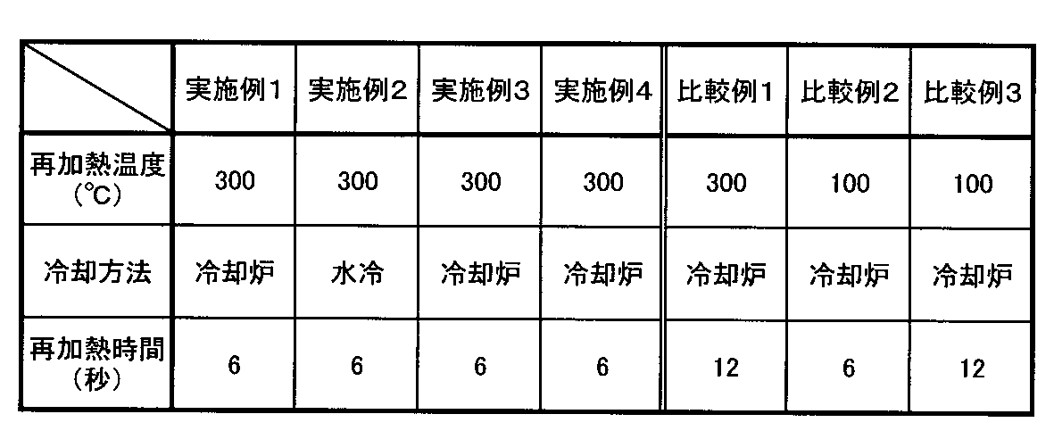
得られた樹脂・金属複合積層材について、それぞれ、樹脂層の結晶化指数を以下の方法で調べ、結果を表2に示した。
[結晶化指数]
樹脂・金属複合積層材を、パーキンエルマー社製の示差走査型熱量計(DSC)を用いて30~300℃の温度範囲において昇温速度10℃/minで昇温し、このときの結晶融解熱量(第1回結晶融解熱量Hm1)と結晶化発熱量(第1回結晶化発熱量Hc1)を測定し、その後30℃まで放冷した後、再び30~300℃の温度範囲において昇温速度10℃/minで昇温した際の結晶融解熱量(第2回結晶融解熱量Hm2)と結晶化発熱量(第2回結晶化発熱量Hc2)を測定した(この値を表2に示す。)。これらの値から、下記(I)式で結晶化指数を算出した。
樹脂・金属複合積層材を、パーキンエルマー社製の示差走査型熱量計(DSC)を用いて30~300℃の温度範囲において昇温速度10℃/minで昇温し、このときの結晶融解熱量(第1回結晶融解熱量Hm1)と結晶化発熱量(第1回結晶化発熱量Hc1)を測定し、その後30℃まで放冷した後、再び30~300℃の温度範囲において昇温速度10℃/minで昇温した際の結晶融解熱量(第2回結晶融解熱量Hm2)と結晶化発熱量(第2回結晶化発熱量Hc2)を測定した(この値を表2に示す。)。これらの値から、下記(I)式で結晶化指数を算出した。

次いで、各樹脂・金属複合積層材を、射出成形金型内に配置し、MXD6ナイロン(三菱エンジニアリングプラスチックス(株)製「レニー(登録商標)NXG5050、融点:243℃)の溶融樹脂(樹脂温度275℃)を射出して、金型温度160℃で射出成形を行って、樹脂・金属複合積層材の樹脂層面に半径3.425mm、高さ15mmの円柱状凸部が一体成形された引張試験用サンプルを製造した。
得られた引張試験用サンプルについて、以下の方法で引張試験を行い、結果を表2に示した。
[引張試験]
引張試験用サンプルの円柱状凸部を引張速度5mm/minで樹脂・金属複合積層材と離反方向に引っ張り、凸部が樹脂層から破断したときの強度を測定し、これを接着強度とした。
接着強度は8MPa以上で合格とした。
引張試験用サンプルの円柱状凸部を引張速度5mm/minで樹脂・金属複合積層材と離反方向に引っ張り、凸部が樹脂層から破断したときの強度を測定し、これを接着強度とした。
接着強度は8MPa以上で合格とした。
[参考例1]
66ナイロン樹脂(東レ社製「CM3001-N」、融点265℃)を2本のヒートロール間で溶融させ、厚み25μmの66ナイロンフィルムを得た。
6ナイロンフィルムの代りにこの66ナイロンフィルムを用いて、実施例1と同様な手順でステンレス鋼板の表面に樹脂層を形成して、樹脂・金属複合積層材を得た。
この樹脂・金属複合積層材を用いて実施例1と同様に引張試験用サンプルを製造し、同様に引張試験を行って結果を表2に示した。
66ナイロン樹脂(東レ社製「CM3001-N」、融点265℃)を2本のヒートロール間で溶融させ、厚み25μmの66ナイロンフィルムを得た。
6ナイロンフィルムの代りにこの66ナイロンフィルムを用いて、実施例1と同様な手順でステンレス鋼板の表面に樹脂層を形成して、樹脂・金属複合積層材を得た。
この樹脂・金属複合積層材を用いて実施例1と同様に引張試験用サンプルを製造し、同様に引張試験を行って結果を表2に示した。
[参考例2]
実施例1で用いたステンレス鋼板を100℃に加熱して、市販のニトリルブタジエンゴム製熱圧着テープ(テサテープ社製、軟化点100℃)を融着して厚さ38μmの樹脂層を形成して樹脂・金属複合積層材を得た。
この樹脂・金属複合積層材を用いて実施例1と同様に引張試験用サンプルを製造し、同様に引張試験を行って結果を表2に示した。
なお、表2には、各例における射出成形時の射出成形金型への樹脂(樹脂・金属複合積層材の樹脂層の樹脂)のべたつきの有(○)無(×)を併記した。
実施例1で用いたステンレス鋼板を100℃に加熱して、市販のニトリルブタジエンゴム製熱圧着テープ(テサテープ社製、軟化点100℃)を融着して厚さ38μmの樹脂層を形成して樹脂・金属複合積層材を得た。
この樹脂・金属複合積層材を用いて実施例1と同様に引張試験用サンプルを製造し、同様に引張試験を行って結果を表2に示した。
なお、表2には、各例における射出成形時の射出成形金型への樹脂(樹脂・金属複合積層材の樹脂層の樹脂)のべたつきの有(○)無(×)を併記した。
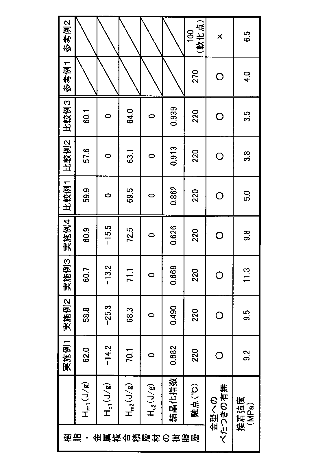
以上の結果より、樹脂層aとして結晶化指数0.40~0.80のポリアミド系樹脂層を形成した本発明の樹脂・金属複合積層材によれば、射出成形により、MXD6ナイロンよりなる凸部を高い接着強度で一体成形することができることが分かる。
なお、参考例1は、樹脂層aの融点が、射出成形する溶融樹脂の融点に比べて高過ぎるものであり、射出成形時に樹脂層aが十分に溶融しないために、金型へのべたつきは無いものの凸部の接着強度が低い。
参考例2は、樹脂層aの融点(軟化点)が射出成形する溶融樹脂の融点に比べて低すぎるものであり、凸部の接着強度は、比較例1~3に比べて高いものの十分ではなく、また、金型内で樹脂層aの樹脂が流動することにより、樹脂のべたつきの問題がある。
参考例2は、樹脂層aの融点(軟化点)が射出成形する溶融樹脂の融点に比べて低すぎるものであり、凸部の接着強度は、比較例1~3に比べて高いものの十分ではなく、また、金型内で樹脂層aの樹脂が流動することにより、樹脂のべたつきの問題がある。
[実施例5~7]
ポリカーボネート系樹脂(PC)(粘度平均分子量25000)とポリブチレンテレフタレート(PBT)(フェノール/テトラクロロエチレン=50/50(体積比)溶液中,30℃での固有粘度1.2448)とを表3に示す質量比率で混合し、280℃に加熱された押出機に供給し、この押出機を用いて280℃で混練し、溶融状態の樹脂組成物をTダイよりシート状に押出し、冷却固化して表3に示す厚さ及び融点の樹脂層b形成フィルムを作製した。
樹脂層aとしての6ナイロンフィルム(厚み:20μm、融点:220℃、結晶化指数:0.40~0.80の範囲、三菱樹脂(株)製「ダイアミロン」)上に、ポリエステル系接着剤とイソシアネート架橋剤とを100質量部:12.5質量部の割合で配合した接着剤を6g/m2塗布して、乾燥炉にて60℃で30秒加熱して乾燥させた後、60℃に加熱したニップロールで、上記樹脂層b形成フィルムをラミネートし、オーブン内にて60℃で5日間養生させてラミネートフィルムを得た。
ポリカーボネート系樹脂(PC)(粘度平均分子量25000)とポリブチレンテレフタレート(PBT)(フェノール/テトラクロロエチレン=50/50(体積比)溶液中,30℃での固有粘度1.2448)とを表3に示す質量比率で混合し、280℃に加熱された押出機に供給し、この押出機を用いて280℃で混練し、溶融状態の樹脂組成物をTダイよりシート状に押出し、冷却固化して表3に示す厚さ及び融点の樹脂層b形成フィルムを作製した。
樹脂層aとしての6ナイロンフィルム(厚み:20μm、融点:220℃、結晶化指数:0.40~0.80の範囲、三菱樹脂(株)製「ダイアミロン」)上に、ポリエステル系接着剤とイソシアネート架橋剤とを100質量部:12.5質量部の割合で配合した接着剤を6g/m2塗布して、乾燥炉にて60℃で30秒加熱して乾燥させた後、60℃に加熱したニップロールで、上記樹脂層b形成フィルムをラミネートし、オーブン内にて60℃で5日間養生させてラミネートフィルムを得た。
ビスフェノールA型エポキシ樹脂をステンレス鋼板(SUS304、1/2H、0.3mm厚)の片面に塗布し、厚さ1μmのプライマー層を形成した。
次いで、前記ラミネートフィルムを、6ナイロンフィルム側がステンレス鋼板側となるようにして、300℃に加熱したステンレス鋼板と溶着し、「樹脂層/接着剤/6ナイロン/エポキシ/SUS」構成の樹脂・金属複合積層材(評価サンプル)を得た。
次いで、前記ラミネートフィルムを、6ナイロンフィルム側がステンレス鋼板側となるようにして、300℃に加熱したステンレス鋼板と溶着し、「樹脂層/接着剤/6ナイロン/エポキシ/SUS」構成の樹脂・金属複合積層材(評価サンプル)を得た。
[比較例4]
ステンレス鋼板(SUS304、1/2H、0.3mm厚)の表面に、シランカップリング剤1%水溶液をバーコーターで20g/m2塗布して、110℃で30秒加熱して乾燥させ、次いで、その塗布面にポリウレタンフィルム(クラボウ社製商品名「U-1250」)を融着して「樹脂層/アミノシラン/SUS」構成の積層材(評価サンプル)を得た。
ステンレス鋼板(SUS304、1/2H、0.3mm厚)の表面に、シランカップリング剤1%水溶液をバーコーターで20g/m2塗布して、110℃で30秒加熱して乾燥させ、次いで、その塗布面にポリウレタンフィルム(クラボウ社製商品名「U-1250」)を融着して「樹脂層/アミノシラン/SUS」構成の積層材(評価サンプル)を得た。
[比較例5]
予め170℃に加熱したステンレス鋼板(SUS304、1/2H、0.3mm厚)に、厚さ50μmのポリエステル系接着フィルム(クラボウ社製商品名「クランベターG13)を融着して「樹脂層/SUS」構成の積層材(評価サンプル)を得た。
予め170℃に加熱したステンレス鋼板(SUS304、1/2H、0.3mm厚)に、厚さ50μmのポリエステル系接着フィルム(クラボウ社製商品名「クランベターG13)を融着して「樹脂層/SUS」構成の積層材(評価サンプル)を得た。
[比較例6]
予め170℃に加熱したステンレス鋼板(SUS304、1/2H、0.3mm厚)に、厚さ30μmのポリエステル系接着フィルム(東亞合成社製、商品名「アロンメルトPES111EE)を融着し、さらにその上に、厚さ130μmのポリカーボネートシートを170℃でラミネートして「樹脂層/接着フィルム/SUS」構成の積層材(評価サンプル)を得た。
予め170℃に加熱したステンレス鋼板(SUS304、1/2H、0.3mm厚)に、厚さ30μmのポリエステル系接着フィルム(東亞合成社製、商品名「アロンメルトPES111EE)を融着し、さらにその上に、厚さ130μmのポリカーボネートシートを170℃でラミネートして「樹脂層/接着フィルム/SUS」構成の積層材(評価サンプル)を得た。
[評価方法]
実施例及び比較例4~6で得たサンプルの評価方法及び評価結果について説明する。
実施例及び比較例4~6で得たサンプルの評価方法及び評価結果について説明する。
<射出成形樹脂との接着性>
290℃に加熱して溶融したポリカーボネート樹脂を、評価サンプルの樹脂上に、射出成形した(射出形状:半径3.425mmの円柱状)。次に、垂直方向に引張試験(引張速度:5mm/min)を行い、破断した強度を測定した。
この際、環境試験後の強度変化を測定した。環境試験は、恒温槽にて85℃で96時間保持する一方、恒温恒湿槽にて60℃で95%RHの環境下で96時間保持した。
結果を表3に示す。
290℃に加熱して溶融したポリカーボネート樹脂を、評価サンプルの樹脂上に、射出成形した(射出形状:半径3.425mmの円柱状)。次に、垂直方向に引張試験(引張速度:5mm/min)を行い、破断した強度を測定した。
この際、環境試験後の強度変化を測定した。環境試験は、恒温槽にて85℃で96時間保持する一方、恒温恒湿槽にて60℃で95%RHの環境下で96時間保持した。
結果を表3に示す。

実施例5~7のサンプルは、初期接着及び環境試験後も良好な接着性(剥離強度)を示した。これに対し、比較例4及び5のサンプルは、初期接着は良好であったが、環境試験後に接着性(剥離強度)が大きく低下した。比較例6のサンプルは、初期強度が低かった。
<耐熱性>
金型温度を80℃、100℃又は120℃に設定して、加熱溶融したポリカーボネート樹脂を、評価サンプルの樹脂層上に射出成形し(射出形状:半径3.425mmの円柱状)、この際に表面及び内部に外観の変化がないか否かを目視にて観察し、以下の基準で評価した。
金型温度を80℃、100℃又は120℃に設定して、加熱溶融したポリカーボネート樹脂を、評価サンプルの樹脂層上に射出成形し(射出形状:半径3.425mmの円柱状)、この際に表面及び内部に外観の変化がないか否かを目視にて観察し、以下の基準で評価した。
○:変化無し
△:表面荒れあり
×:剥がれあり
△:表面荒れあり
×:剥がれあり
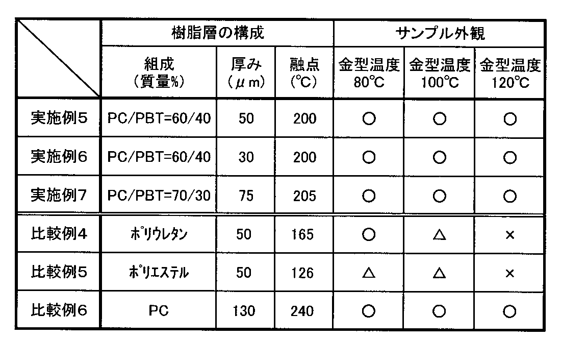
実施例5~7のサンプルは、金型温度が120℃であっても、表面及び内部に外観の変化は見られなかった。これに対し、比較例4のサンプルは、80℃では良かったが、100℃以上になると、表面が溶けてしまった。また、比較例5のサンプルは、80℃及び100℃の両温度において表面が溶解し、表面荒れが生じた。また、比較例6のサンプルは、実施例5~7のサンプルと同様、フィルム表面及び内部に外観変化は見られなかった。
<エリクセン試験>
Fig.5a~5cに示す方法でエリクセン試験を行った。
先ず、Fig.5aに示すように、サンプル31の表面に切込み32を入れ(5mm間隔)、次に、Fig.5bに示すように、JISK6744で規定されるエリクセン試験装置を用いて、サンプル31の中心部分に、先端が球状のポンチ33を5mm~7mm押し込み(Fig.5b中、34はダイス、35はしわ押さえである。)、Fig.5cに示すように、サンプル31に浮きやひび割れが生じていないか観察し、次の基準で評価した。結果を表5に示す。
Fig.5a~5cに示す方法でエリクセン試験を行った。
先ず、Fig.5aに示すように、サンプル31の表面に切込み32を入れ(5mm間隔)、次に、Fig.5bに示すように、JISK6744で規定されるエリクセン試験装置を用いて、サンプル31の中心部分に、先端が球状のポンチ33を5mm~7mm押し込み(Fig.5b中、34はダイス、35はしわ押さえである。)、Fig.5cに示すように、サンプル31に浮きやひび割れが生じていないか観察し、次の基準で評価した。結果を表5に示す。
○:剥離及び、ひび割れ無し
△:ひび割れあり
×:剥離あり
△:ひび割れあり
×:剥離あり

実施例5~7及び比較例4のサンプルについては、押出距離が7mmであっても、サンプルに浮きやひび割れが生じていなかった。
これに対し、比較例5のサンプルは、5mmで既に剥離が観察され、比較例6のサンプルは、5mm及び7mmで押し出すといずれもフィルムにひびが多く生じた。
これに対し、比較例5のサンプルは、5mmで既に剥離が観察され、比較例6のサンプルは、5mm及び7mmで押し出すといずれもフィルムにひびが多く生じた。
[実施例8]
アルミニウム合金板(A5182 H18 0.3mm厚)に、実施例6と同様のラミネートフィルムを同様な方法で積層し、サンプルを得た。金型温度を120℃に設定して加熱溶融したポリカーボネート樹脂を、評価サンプルのフィルム上に成形した(射出形状:半径3.425mmの円柱状)。
アルミニウム合金板(A5182 H18 0.3mm厚)に、実施例6と同様のラミネートフィルムを同様な方法で積層し、サンプルを得た。金型温度を120℃に設定して加熱溶融したポリカーボネート樹脂を、評価サンプルのフィルム上に成形した(射出形状:半径3.425mmの円柱状)。
[実施例9]
実施例8と同様のサンプルにポリカーボネート樹脂を射出成形した後に、90℃に加熱したリン酸50質量%及び硝酸5質量%の水溶液に30秒浸漬し、10質量%硫酸水溶液でデスマット処理を行った後、サンプルに電極を付け、20℃に調整した20質量%硫酸水溶液に浸漬し、電流密度150A/m2で通電を行い、金属表面に12μmのアルマイト膜を得た。続いて、有機染料で赤色に着色し、95℃の温水に2分浸漬し封孔処理を行った。
実施例8と同様のサンプルにポリカーボネート樹脂を射出成形した後に、90℃に加熱したリン酸50質量%及び硝酸5質量%の水溶液に30秒浸漬し、10質量%硫酸水溶液でデスマット処理を行った後、サンプルに電極を付け、20℃に調整した20質量%硫酸水溶液に浸漬し、電流密度150A/m2で通電を行い、金属表面に12μmのアルマイト膜を得た。続いて、有機染料で赤色に着色し、95℃の温水に2分浸漬し封孔処理を行った。
[実施例10]
実施例8と同様のサンプルにポリカーボネート樹脂を射出成形した後に、55℃に加熱した水酸化ナトリウム15質量%の水溶液に180秒浸漬し、10質量%硫酸水溶液でデスマット処理を行った後、サンプルに電極を付け、20℃に調整した20質量%硫酸水溶液に浸漬し、電流密度150A/m2で通電を行い、金属表面に12μmのアルマイト膜を得た。続いて、有機染料で金色に着色し、95℃の温水に2分浸漬し封孔処理を行った。
実施例8と同様のサンプルにポリカーボネート樹脂を射出成形した後に、55℃に加熱した水酸化ナトリウム15質量%の水溶液に180秒浸漬し、10質量%硫酸水溶液でデスマット処理を行った後、サンプルに電極を付け、20℃に調整した20質量%硫酸水溶液に浸漬し、電流密度150A/m2で通電を行い、金属表面に12μmのアルマイト膜を得た。続いて、有機染料で金色に着色し、95℃の温水に2分浸漬し封孔処理を行った。
実施例8~10で得られたサンプルを、垂直方向に引張試験(引張速度5mm/min)を行い、破断した強度を射出接着強度として測定した。結果を表6に示す。

表6より射出成形後にアルマイト処理を行った場合(実施例9及び10)においてもアルマイト処理を行っていない場合(実施例8)と同等の接着力が得られ、射出接着強度の低下は許容範囲であった。
本発明を特定の態様を用いて詳細に説明したが、本発明の意図と範囲を離れることなく様々な変更が可能であることは当業者に明らかである。
なお、本出願は、2010年2月4日付で出願された日本特許出願(特願2010-023143)に基づいており、その全体が引用により援用される。
なお、本出願は、2010年2月4日付で出願された日本特許出願(特願2010-023143)に基づいており、その全体が引用により援用される。
1,1a,1b 樹脂・金属複合積層材
1A 金属板
1B 樹脂層(樹脂層a、或いは樹脂層aと樹脂層bの積層樹脂層)
1C プライマー層
2 樹脂・金属複合射出成形体
3 凸部
4 射出成形金型
5 射出成形機
6 溶融樹脂
24 加熱炉
26 樹脂フィルム
28 再加熱炉
29 樹脂・金属複合積層材
31 サンプル
32 切込み
33 ポンチ
34 ダイス
35 しわ押え
1A 金属板
1B 樹脂層(樹脂層a、或いは樹脂層aと樹脂層bの積層樹脂層)
1C プライマー層
2 樹脂・金属複合射出成形体
3 凸部
4 射出成形金型
5 射出成形機
6 溶融樹脂
24 加熱炉
26 樹脂フィルム
28 再加熱炉
29 樹脂・金属複合積層材
31 サンプル
32 切込み
33 ポンチ
34 ダイス
35 しわ押え
Claims (19)
- 金属板と、該金属板の少なくとも一方の面に積層されたポリアミド系樹脂を主成分とする樹脂層とを有する樹脂・金属複合積層材であって、
下記式(I)で算出される、前記樹脂層aの結晶化指数が0.40~0.80であることを特徴とする樹脂・金属複合積層材。

- 請求項1において、前記樹脂層aに含まれるポリアミド系樹脂が6ナイロンであることを特徴とする樹脂・金属複合積層材。
- 請求項1又は2において、前記樹脂層aの厚さが5~100μmであり、前記金属板の厚さが0.03~3.0mmであることを特徴とする樹脂・金属複合積層材。
- 請求項1ないし3のいずれか1項において、前記樹脂層a上に、ポリカーボネート系樹脂とポリエステル系樹脂との混合樹脂を主成分とする第2の樹脂層bをさらに有することを特徴とする樹脂・金属複合積層材。
- 請求項4において、前記樹脂層bに含まれるポリカーボネート系樹脂とポリエステル系樹脂との混合比が、ポリカーボネート系樹脂:ポリエステル系樹脂=20:80~70:30であることを特徴とする樹脂・金属複合積層材。
- 請求項4又は5において、前記樹脂層bに含まれるポリエステル系樹脂が、ポリブチレンテレフタレートであることを特徴とする樹脂・金属複合積層材。
- 請求項4ないし6のいずれか1項において、インモールド成形に用いることを特徴とする樹脂・金属複合積層材。
- 請求項1ないし3のいずれか1項において、前記樹脂層a上に、合成樹脂よりなる凸部を射出成形により一体的に形成するための樹脂・金属複合積層材であることを特徴とする樹脂・金属複合積層材。
- 請求項4ないし7のいずれか1項において、前記樹脂層b上に、合成樹脂よりなる凸部を射出成形により一体的に形成するための樹脂・金属複合積層材であることを特徴とする樹脂・金属複合積層材。
- 請求項8又は9において、前記樹脂層a、前記樹脂層b、又は前記樹脂層a及び樹脂層bを構成する樹脂の融点が、前記凸部を構成する合成樹脂の融点よりも10~60℃低いことを特徴とする樹脂・金属複合積層材。
- 請求項10において、前記凸部を構成する合成樹脂がMXD6ナイロンであることを特徴とする樹脂・金属複合積層材。
- 請求項10において、前記凸部を構成する合成樹脂がポリカーボネート系樹脂であることを特徴とする樹脂・金属複合積層材。
- 請求項1ないし12のいずれか1項において、前記金属板の前記樹脂層a或いは前記樹脂層a及び樹脂層bが形成された面とは反対側の面が、アルマイト加工処理されていることを特徴とする樹脂・金属複合積層材。
- 請求項1ないし13のいずれか1項において、前記金属板の前記樹脂層a或いは前記樹脂層a及び樹脂層bが形成された面とは反対側の面に塗布用フィルム層と樹脂塗布層とをこの順に有することを特徴とする樹脂・金属複合積層材。
- 請求項1ないし14のいずれか1項に記載の樹脂・金属複合積層材の樹脂層a又は樹脂層b上に合成樹脂の溶融樹脂を射出成形することにより、該合成樹脂よりなる凸部を一体的に成形してなることを特徴とする樹脂・金属複合射出成形体。
- 請求項15に記載の樹脂・金属複合射出成形体を含むことを特徴とするOA機器用又は電子機器用の筐体。
- 請求項16において、携帯電話の筐体であることを特徴とするOA機器用又は電子機器用の筐体。
- 請求項1ないし14のいずれか1項に記載の樹脂・金属複合積層材を製造する方法であって、前記金属板に樹脂フィルムを溶着するラミネート工程を有することを特徴とする樹脂・金属複合積層材の製造方法。
- 請求項15に記載の樹脂・金属複合射出成形体を製造する方法であって、前記樹脂・金属複合積層材を配置した射出成形金型内に、前記溶融樹脂を射出して前記凸部を一体成形する工程を有することを特徴とする樹脂・金属複合射出成形体の製造方法。
Priority Applications (1)
| Application Number | Priority Date | Filing Date | Title |
|---|---|---|---|
| CN201080062992.0A CN102753342B (zh) | 2010-02-04 | 2010-07-14 | 树脂/金属复合叠层材料、树脂/金属复合注塑成型体、及其制造方法 |
Applications Claiming Priority (2)
| Application Number | Priority Date | Filing Date | Title |
|---|---|---|---|
| JP2010023143A JP5499741B2 (ja) | 2010-02-04 | 2010-02-04 | 樹脂・金属積層材、樹脂・金属複合射出成形体、及びその製造方法 |
| JP2010-023143 | 2010-02-04 |
Publications (1)
| Publication Number | Publication Date |
|---|---|
| WO2011096100A1 true WO2011096100A1 (ja) | 2011-08-11 |
Family
ID=44355123
Family Applications (1)
| Application Number | Title | Priority Date | Filing Date |
|---|---|---|---|
| PCT/JP2010/061887 Ceased WO2011096100A1 (ja) | 2010-02-04 | 2010-07-14 | 樹脂・金属複合積層材、樹脂・金属複合射出成形体、及びその製造方法 |
Country Status (4)
| Country | Link |
|---|---|
| JP (1) | JP5499741B2 (ja) |
| CN (1) | CN102753342B (ja) |
| TW (1) | TWI507287B (ja) |
| WO (1) | WO2011096100A1 (ja) |
Cited By (2)
| Publication number | Priority date | Publication date | Assignee | Title |
|---|---|---|---|---|
| CN104853896A (zh) * | 2012-10-15 | 2015-08-19 | 莱昂哈德库尔兹基金会及两合公司 | 通过模内工艺制造的主体和用于制造该主体的方法 |
| WO2020076932A1 (en) * | 2018-10-09 | 2020-04-16 | Dupont Polymers, Inc. | Polymer metal hybrid laminates |
Families Citing this family (14)
| Publication number | Priority date | Publication date | Assignee | Title |
|---|---|---|---|---|
| TW201313484A (zh) * | 2011-09-27 | 2013-04-01 | Ichia Tech Inc | 金屬殼體具有塑膠機構之複合件 |
| CN103079367A (zh) * | 2011-10-25 | 2013-05-01 | 毅嘉科技股份有限公司 | 金属壳体具有塑胶机构的复合件 |
| JP2013245798A (ja) * | 2012-05-29 | 2013-12-09 | Nok Corp | フィルター付きガスケット |
| JP6021066B2 (ja) * | 2013-01-10 | 2016-11-02 | パナソニックIpマネジメント株式会社 | 断熱パネル |
| JP6017675B2 (ja) * | 2013-03-26 | 2016-11-02 | 日本軽金属株式会社 | 金属樹脂接合体及びその製造方法 |
| JP6525871B2 (ja) * | 2013-06-20 | 2019-06-05 | 三菱瓦斯化学株式会社 | フィルムとフィルムを成形するための成形方法、金型、およびフィルムを含む成形品とその成形方法 |
| KR101950899B1 (ko) * | 2014-04-04 | 2019-05-10 | 알프스 알파인 가부시키가이샤 | 전자부품의 제조 방법 |
| JP6224017B2 (ja) * | 2015-02-18 | 2017-11-01 | 大成プラス株式会社 | Cfrtp複合体の製造方法 |
| JP6668174B2 (ja) * | 2015-11-13 | 2020-03-18 | 三菱エンジニアリングプラスチックス株式会社 | 樹脂金属複合体及びその製造方法 |
| EP3393702A1 (en) * | 2015-12-23 | 2018-10-31 | SABIC Global Technologies B.V. | Hybrid metal-plastic parts and process for manufacturing the same |
| JP7130219B2 (ja) * | 2016-10-24 | 2022-09-05 | タイガー魔法瓶株式会社 | 真空二重容器 |
| JP6979847B2 (ja) * | 2017-10-16 | 2021-12-15 | 昭和電工パッケージング株式会社 | 蓄電デバイス用外装材及び蓄電デバイス |
| US11701864B2 (en) | 2017-10-27 | 2023-07-18 | Mitsui Chemicals, Inc. | Metal/resin composite structure and manufacturing method of metal/resin composite structure |
| JP7358792B2 (ja) * | 2019-06-13 | 2023-10-12 | 株式会社レゾナック | 電子基板筐体及びその製造方法 |
Citations (3)
| Publication number | Priority date | Publication date | Assignee | Title |
|---|---|---|---|---|
| JPH0598465A (ja) * | 1991-03-29 | 1993-04-20 | Toyo Kohan Co Ltd | 加工耐食性に優れた薄肉化深絞り缶用樹脂被覆錫めつ き鋼板の製造方法 |
| JP2007320215A (ja) * | 2006-06-02 | 2007-12-13 | Sumitomo Light Metal Ind Ltd | プレコートアルミニウム合金板 |
| JP2008188970A (ja) * | 2007-02-08 | 2008-08-21 | Mitsubishi Plastics Ind Ltd | 積層シートおよび積層シート被覆金属板 |
Family Cites Families (5)
| Publication number | Priority date | Publication date | Assignee | Title |
|---|---|---|---|---|
| JP3575812B2 (ja) * | 1992-07-31 | 2004-10-13 | 住友化学工業株式会社 | 多層成形品およびその製造方法 |
| JPH0929778A (ja) * | 1995-07-18 | 1997-02-04 | Matsushita Electric Ind Co Ltd | 樹脂射出成形方法とその製品 |
| JP2001315159A (ja) * | 2000-05-10 | 2001-11-13 | Mitsubishi Plastics Ind Ltd | 金属板を有する射出成形品の製造方法 |
| JP2002046213A (ja) * | 2000-08-04 | 2002-02-12 | Kobe Steel Ltd | 電子部品ケース用樹脂被覆積層アルミニウム板およびその製造方法ならびに電子部品ケース |
| CN100500427C (zh) * | 2002-12-26 | 2009-06-17 | 三菱树脂株式会社 | 树脂覆盖金属板、树脂覆盖金属板用的图案设计薄板及树脂覆盖金属板的制造方法 |
-
2010
- 2010-02-04 JP JP2010023143A patent/JP5499741B2/ja active Active
- 2010-07-14 CN CN201080062992.0A patent/CN102753342B/zh active Active
- 2010-07-14 WO PCT/JP2010/061887 patent/WO2011096100A1/ja not_active Ceased
- 2010-07-15 TW TW099123431A patent/TWI507287B/zh active
Patent Citations (3)
| Publication number | Priority date | Publication date | Assignee | Title |
|---|---|---|---|---|
| JPH0598465A (ja) * | 1991-03-29 | 1993-04-20 | Toyo Kohan Co Ltd | 加工耐食性に優れた薄肉化深絞り缶用樹脂被覆錫めつ き鋼板の製造方法 |
| JP2007320215A (ja) * | 2006-06-02 | 2007-12-13 | Sumitomo Light Metal Ind Ltd | プレコートアルミニウム合金板 |
| JP2008188970A (ja) * | 2007-02-08 | 2008-08-21 | Mitsubishi Plastics Ind Ltd | 積層シートおよび積層シート被覆金属板 |
Cited By (3)
| Publication number | Priority date | Publication date | Assignee | Title |
|---|---|---|---|---|
| CN104853896A (zh) * | 2012-10-15 | 2015-08-19 | 莱昂哈德库尔兹基金会及两合公司 | 通过模内工艺制造的主体和用于制造该主体的方法 |
| CN104853896B (zh) * | 2012-10-15 | 2018-06-05 | 莱昂哈德库尔兹基金会及两合公司 | 通过模内工艺制造的主体和用于制造该主体的方法 |
| WO2020076932A1 (en) * | 2018-10-09 | 2020-04-16 | Dupont Polymers, Inc. | Polymer metal hybrid laminates |
Also Published As
| Publication number | Publication date |
|---|---|
| CN102753342B (zh) | 2015-06-24 |
| TW201127618A (en) | 2011-08-16 |
| JP5499741B2 (ja) | 2014-05-21 |
| JP2011161634A (ja) | 2011-08-25 |
| TWI507287B (zh) | 2015-11-11 |
| CN102753342A (zh) | 2012-10-24 |
Similar Documents
| Publication | Publication Date | Title |
|---|---|---|
| WO2011096100A1 (ja) | 樹脂・金属複合積層材、樹脂・金属複合射出成形体、及びその製造方法 | |
| CN102905895B (zh) | 多层膜、装饰成型用膜以及成型体 | |
| CN103826846B (zh) | 容器用树脂被覆金属板 | |
| EP3698963B1 (en) | Method for producing metal member, method for producing resin member, and method for producing exterior part | |
| JP5358994B2 (ja) | 容器用ポリエステル樹脂被覆金属板 | |
| JP7088434B1 (ja) | 蓄電デバイス用外装材、その製造方法、及び蓄電デバイス | |
| JP7160224B1 (ja) | 蓄電デバイス用外装材、その製造方法、及び蓄電デバイス | |
| JP7299974B2 (ja) | 電子機器筐体、その製造方法および金属樹脂複合体 | |
| WO2010116952A1 (ja) | 樹脂被覆金属板及びこれから成るシームレス缶 | |
| JP5185144B2 (ja) | 樹脂・金属複合積層材 | |
| JP7307398B2 (ja) | 積層フィルム | |
| JP4654084B2 (ja) | 金属板被覆用積層シート、および積層シート被覆金属板 | |
| JP4664111B2 (ja) | 意匠性積層シート、および意匠性積層シート被覆金属板 | |
| JP5605012B2 (ja) | 容器用樹脂被覆金属板 | |
| CN100567091C (zh) | 易开盖 | |
| JP3750973B2 (ja) | 金属板ラミネート用未延伸積層フィルム及び該フィルムで被覆された金属板 | |
| JP5962369B2 (ja) | 容器用樹脂被覆金属板 | |
| JPH1034663A (ja) | 断熱金型およびそれを用いる樹脂成形法 | |
| JPH0919928A (ja) | 断熱層被覆金型及びその製法 | |
| TWI725389B (zh) | 用於電子裝置之裝飾面板及其製造方法 | |
| JP2008100383A (ja) | 積層シ−ト、エンボス意匠シートおよびエンボス意匠シート被覆金属板 | |
| JPH10175222A (ja) | 断熱層被覆金型の製法及び該金型を用いた合成樹脂の成形法 | |
| JPH10202788A (ja) | 金属板積層体 | |
| JPH10156835A (ja) | 断熱金型およびその製造法 | |
| JPS6230910B2 (ja) |
Legal Events
| Date | Code | Title | Description |
|---|---|---|---|
| WWE | Wipo information: entry into national phase |
Ref document number: 201080062992.0 Country of ref document: CN |
|
| 121 | Ep: the epo has been informed by wipo that ep was designated in this application |
Ref document number: 10845232 Country of ref document: EP Kind code of ref document: A1 |
|
| NENP | Non-entry into the national phase |
Ref country code: DE |
|
| 122 | Ep: pct application non-entry in european phase |
Ref document number: 10845232 Country of ref document: EP Kind code of ref document: A1 |