WO2011089812A1 - 車両周辺監視装置 - Google Patents
車両周辺監視装置 Download PDFInfo
- Publication number
- WO2011089812A1 WO2011089812A1 PCT/JP2010/072973 JP2010072973W WO2011089812A1 WO 2011089812 A1 WO2011089812 A1 WO 2011089812A1 JP 2010072973 W JP2010072973 W JP 2010072973W WO 2011089812 A1 WO2011089812 A1 WO 2011089812A1
- Authority
- WO
- WIPO (PCT)
- Prior art keywords
- vehicle
- obstacle
- predicted
- monitoring device
- area
- Prior art date
- Legal status (The legal status is an assumption and is not a legal conclusion. Google has not performed a legal analysis and makes no representation as to the accuracy of the status listed.)
- Ceased
Links
Images


Classifications
-
- B—PERFORMING OPERATIONS; TRANSPORTING
- B60—VEHICLES IN GENERAL
- B60R—VEHICLES, VEHICLE FITTINGS, OR VEHICLE PARTS, NOT OTHERWISE PROVIDED FOR
- B60R1/00—Optical viewing arrangements; Real-time viewing arrangements for drivers or passengers using optical image capturing systems, e.g. cameras or video systems specially adapted for use in or on vehicles
- B60R1/20—Real-time viewing arrangements for drivers or passengers using optical image capturing systems, e.g. cameras or video systems specially adapted for use in or on vehicles
- B60R1/22—Real-time viewing arrangements for drivers or passengers using optical image capturing systems, e.g. cameras or video systems specially adapted for use in or on vehicles for viewing an area outside the vehicle, e.g. the exterior of the vehicle
- B60R1/23—Real-time viewing arrangements for drivers or passengers using optical image capturing systems, e.g. cameras or video systems specially adapted for use in or on vehicles for viewing an area outside the vehicle, e.g. the exterior of the vehicle with a predetermined field of view
- B60R1/26—Real-time viewing arrangements for drivers or passengers using optical image capturing systems, e.g. cameras or video systems specially adapted for use in or on vehicles for viewing an area outside the vehicle, e.g. the exterior of the vehicle with a predetermined field of view to the rear of the vehicle
-
- B—PERFORMING OPERATIONS; TRANSPORTING
- B62—LAND VEHICLES FOR TRAVELLING OTHERWISE THAN ON RAILS
- B62D—MOTOR VEHICLES; TRAILERS
- B62D15/00—Steering not otherwise provided for
- B62D15/02—Steering position indicators ; Steering position determination; Steering aids
- B62D15/027—Parking aids, e.g. instruction means
- B62D15/0275—Parking aids, e.g. instruction means by overlaying a vehicle path based on present steering angle over an image without processing that image
-
- G—PHYSICS
- G08—SIGNALLING
- G08G—TRAFFIC CONTROL SYSTEMS
- G08G1/00—Traffic control systems for road vehicles
- G08G1/16—Anti-collision systems
- G08G1/166—Anti-collision systems for active traffic, e.g. moving vehicles, pedestrians, bikes
-
- G—PHYSICS
- G08—SIGNALLING
- G08G—TRAFFIC CONTROL SYSTEMS
- G08G1/00—Traffic control systems for road vehicles
- G08G1/16—Anti-collision systems
- G08G1/168—Driving aids for parking, e.g. acoustic or visual feedback on parking space
-
- B—PERFORMING OPERATIONS; TRANSPORTING
- B60—VEHICLES IN GENERAL
- B60R—VEHICLES, VEHICLE FITTINGS, OR VEHICLE PARTS, NOT OTHERWISE PROVIDED FOR
- B60R2300/00—Details of viewing arrangements using cameras and displays, specially adapted for use in a vehicle
- B60R2300/30—Details of viewing arrangements using cameras and displays, specially adapted for use in a vehicle characterised by the type of image processing
- B60R2300/301—Details of viewing arrangements using cameras and displays, specially adapted for use in a vehicle characterised by the type of image processing combining image information with other obstacle sensor information, e.g. using RADAR/LIDAR/SONAR sensors for estimating risk of collision
-
- B—PERFORMING OPERATIONS; TRANSPORTING
- B60—VEHICLES IN GENERAL
- B60R—VEHICLES, VEHICLE FITTINGS, OR VEHICLE PARTS, NOT OTHERWISE PROVIDED FOR
- B60R2300/00—Details of viewing arrangements using cameras and displays, specially adapted for use in a vehicle
- B60R2300/30—Details of viewing arrangements using cameras and displays, specially adapted for use in a vehicle characterised by the type of image processing
- B60R2300/307—Details of viewing arrangements using cameras and displays, specially adapted for use in a vehicle characterised by the type of image processing virtually distinguishing relevant parts of a scene from the background of the scene
-
- B—PERFORMING OPERATIONS; TRANSPORTING
- B60—VEHICLES IN GENERAL
- B60R—VEHICLES, VEHICLE FITTINGS, OR VEHICLE PARTS, NOT OTHERWISE PROVIDED FOR
- B60R2300/00—Details of viewing arrangements using cameras and displays, specially adapted for use in a vehicle
- B60R2300/80—Details of viewing arrangements using cameras and displays, specially adapted for use in a vehicle characterised by the intended use of the viewing arrangement
- B60R2300/806—Details of viewing arrangements using cameras and displays, specially adapted for use in a vehicle characterised by the intended use of the viewing arrangement for aiding parking
-
- B—PERFORMING OPERATIONS; TRANSPORTING
- B60—VEHICLES IN GENERAL
- B60R—VEHICLES, VEHICLE FITTINGS, OR VEHICLE PARTS, NOT OTHERWISE PROVIDED FOR
- B60R2300/00—Details of viewing arrangements using cameras and displays, specially adapted for use in a vehicle
- B60R2300/80—Details of viewing arrangements using cameras and displays, specially adapted for use in a vehicle characterised by the intended use of the viewing arrangement
- B60R2300/8066—Details of viewing arrangements using cameras and displays, specially adapted for use in a vehicle characterised by the intended use of the viewing arrangement for monitoring rearward traffic
-
- B—PERFORMING OPERATIONS; TRANSPORTING
- B60—VEHICLES IN GENERAL
- B60R—VEHICLES, VEHICLE FITTINGS, OR VEHICLE PARTS, NOT OTHERWISE PROVIDED FOR
- B60R2300/00—Details of viewing arrangements using cameras and displays, specially adapted for use in a vehicle
- B60R2300/80—Details of viewing arrangements using cameras and displays, specially adapted for use in a vehicle characterised by the intended use of the viewing arrangement
- B60R2300/8093—Details of viewing arrangements using cameras and displays, specially adapted for use in a vehicle characterised by the intended use of the viewing arrangement for obstacle warning
Definitions
- the present invention relates to a vehicle periphery monitoring device for highlighting an obstacle on a display device provided in a vehicle cabin to alert a driver.
- Patent Document 1 an apparatus of this type is known. This is to extract an obstacle existing around the vehicle based on a signal obtained from an imaging device for imaging the periphery of the vehicle and display the obstacle on the display device. By changing the display method of the obstacle according to the degree of danger determined by the attribute of the obstacle and the moving direction, etc., the driver can recognize the positional relationship between the own vehicle and the obstacle and the degree of danger There is.
- the vehicle surrounding information display device described in Patent Document 2 displays the obstacle detected by the vehicle surrounding object detecting means by adding risk information to a schematic picture display set in advance.
- the driver can easily grasp the situation around the vehicle by setting the perspective display level of the basic image indicating the surrounding situation that is the background when displaying the obstacle. It is configured.
- Each of the apparatuses described in Patent Documents 1 and 2 adopts a form in which information about the degree of risk is added to the obstacle itself and displayed. Therefore, when a plurality of obstacles exist in the target range, much information may be displayed on the display screen at one time, which may make it difficult for the driver to quickly grasp the surrounding situation. Also, by determining the degree of risk taking into consideration factors other than the distance between the vehicle and the obstacle, such as the attribute and movement direction of the obstacle, the sense of distance to the obstacle displayed on the screen is difficult to grasp Can be considered. Furthermore, it is difficult to intuitively understand whether or not the obstacle can be avoided by the steering operation only by superimposing the obstacle on the surrounding image.
- the present invention has been made in view of the above problems, and a vehicle periphery monitoring device that allows the driver to intuitively grasp the sense of distance between the vehicle and the obstacle without excessive information displayed on the display device. Intended to provide.
- the first characteristic configuration of the vehicle periphery monitoring device includes an image acquisition unit for acquiring an image of the periphery of the vehicle taken by an imaging device provided in the vehicle, an obstacle around the vehicle, and the position thereof.
- a traveling state detection unit that detects the traveling state of the vehicle
- a predicted track line generation unit that generates a predicted track based on the traveling state of the vehicle detected by the traveling state detection unit
- a highlight determining unit configured to determine highlighting of a partial area including the obstacle in the predicted course area when the obstacle is present in the predicted course area defined by the predicted course line
- a display control unit for superimposing the predicted course line and the highlighted display on a peripheral image and displaying the superimposed image on a display device provided in a vehicle compartment of the vehicle.
- the driver can refer to the predicted track by referring to the predicted track. It is easy to intuitively grasp the sense of distance between your own vehicle and an obstacle.
- the obstacle itself is not highlighted individually but the area including the obstacle is highlighted, if there are many obstacles, it is troublesome to be highlighted for each obstacle. Can be avoided.
- the driver can easily recognize the presence of the obstacle because the area including the obstacle is highlighted.
- a second feature configuration is that the highlighting is performed in each of regions obtained by dividing the predicted travel region at least in the perspective direction in advance.
- the highlighting is performed for each of the divided regions in the perspective direction, it is easy to grasp the sense of distance between the highlighted region and the vehicle. Therefore, the driver can easily grasp the distance to the obstacle, and the operation for avoiding the obstacle can be easily performed.
- a third characteristic configuration is that the display control unit displays a side surface portion on the side closer to the imaging device of the predicted course line.
- the predicted course line is three-dimensionally represented, it is easy to grasp the sense of distance between the vehicle and the obstacle with reference to the predicted course line.
- a fourth characteristic configuration is that the display control unit displays a shadowed portion on the side closer to the imaging device of the predicted course line.
- the predicted course line is three-dimensionally represented, it is easy to grasp the sense of distance between the vehicle and the obstacle with reference to the predicted course line.
- the highlighting is performed by filling the partial area.
- the driver when highlighting is performed by filling in the area, the driver can easily recognize the highlighting, so the risk of overlooking an obstacle can be reduced.
- a sixth feature resides in that the fill is translucent.
- the peripheral image to be the background of the highlighting can also be seen through. Therefore, in combination with the highlighting, the obstacle that is actually present can be recognized on the display device. As a result, the positional relationship between the vehicle and the obstacle can be easily grasped, and the operation for avoiding the obstacle can be easily performed.
- a seventh feature lies in that the color of the fill is changed according to the distance between the vehicle and the obstacle.
- the fill color is a reddish color having a warning meaning as the distance to the vehicle is closer, and a green or bluish color as the distance is longer, the self color is selected. It becomes easy to intuitively grasp the distance between the car and the obstacle.
- the eighth feature configuration is that the predicted course line is interlocked with steering of the steering.
- the predicted course area defined by the predicted course line is also interlocked with the steering of the steering. Therefore, even when an obstacle is included in the predicted travel area by steering, the driver highlights the presence of the new obstacle by highlighting the area including the obstacle. It can be easily recognized. In addition, since the predicted travel area moves in conjunction with the steering of the steering, the obstacle avoidance operation becomes easy.
- a ninth characterizing feature is to highlight the obstacle relatively approaching the predicted travel area.
- the driver can easily recognize the presence of the obstacle when the obstacle is relatively approaching the predicted travel area due to the operation of the vehicle or the movement of the obstacle. , It will be easier to avoid obstacles.
- FIG. 1 is a block diagram showing a configuration of a vehicle periphery monitoring device according to the present invention. It is a figure which shows an example of the periphery image displayed on a monitor, and a prediction course line. It is a figure which shows an example of a highlighting. It is a figure which shows an example of a highlighting. It is a figure which shows an example of the highlighting in another embodiment. It is a figure which shows an example of the highlighting in another embodiment. It is a figure which shows an example of the highlighting in another embodiment. It is a figure which shows an example of the highlighting in another embodiment. It is a figure which shows an example of the highlighting in another embodiment. It is a figure which shows an example of the highlighting in another embodiment. It is a figure which shows an example of the highlighting in another embodiment. It is a figure which shows an example of the highlighting in another embodiment. It is a figure which shows an example of the highlighting in another embodiment.
- FIGS. 1 to 6 An embodiment of a vehicle periphery monitoring apparatus according to the present invention will be described with reference to FIGS. 1 to 6.
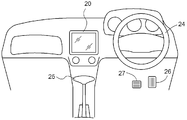
- FIG.1 and FIG.2 is the figure which showed the basic composition of the vehicle 30 provided with the vehicle periphery monitoring apparatus based on this embodiment.
- the steering 24 provided at the driver's seat interlocks with the power steering unit 33, transmits the rotational operation force to the front wheels 28f, and steers the vehicle 30.
- An engine 32 and a transmission mechanism 34 for transmitting power from the engine 32 to the front wheel 28 f and the rear wheel 28 r are disposed at the front of the vehicle 30. Power is transmitted to both or either of the front wheel 28 f and the rear wheel 28 r according to the drive system (front wheel drive, rear wheel drive, four wheel drive) of the vehicle 30.
- an accelerator pedal 26 for controlling the traveling speed and a brake pedal 27 for applying a braking force to the front wheel 28 f and the rear wheel 28 r via the brake device 31 are arranged in parallel.
- a monitor 20 (display device) is provided at an upper position of the console near the driver's seat. In the case of a vehicle 30 provided with a parking assistance device or a navigation system, the monitor 20 may be used also as a display device used for these.
- a steering sensor 14 is provided in the operation system of the steering 24, and the steering direction and the operation amount of the steering 24 are measured.
- a shift position sensor 15 is provided in the operation system of the shift lever 25 to determine the shift position.
- an accelerator sensor 16 is provided in the operation system of the accelerator pedal 26, and a brake sensor 17 is provided in the operation system of the brake pedal 27, and the amount of operation is measured.
- a wheel speed sensor 18 that measures the amount of rotation of the rear wheel 28 r is provided in the vicinity of the rear wheel 28 r. Note that these sensors are not limited to the above configuration, and other configurations may be used as long as substantially the same measurement values can be obtained.
- a camera 12 for shooting an image of a surrounding area behind the vehicle 30 is provided at the center of the rear of the vehicle 30.
- the peripheral image captured by the camera 12 is configured to be displayed on the monitor 20.
- sonars 13 are provided which detect an obstacle present behind the vehicle and measure the distance between the vehicle and the obstacle.
- an ECU Electronic Control Unit 10 10 which is a core of the vehicle periphery monitoring device of the present invention, is disposed in the vehicle 30.
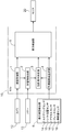
- FIG. 3 is a block diagram showing a configuration example of a vehicle periphery monitoring device according to the present invention.
- the ECU 10 is configured to include an image acquisition unit 1, an obstacle detection unit 2, a highlight display determination unit 3, a predicted track line generation unit 4 and a display control unit 5.
- the function of each functional unit of the ECU 10 is realized by cooperation of hardware such as a microprocessor and software such as a program.
- Each functional unit indicates a division as a function, and does not necessarily have to be configured physically independently.
- the traveling state detection unit 6 is a functional unit that detects a traveling state such as the speed or traveling direction of the vehicle 30, and includes the steering sensor 14, the shift position sensor 15, the accelerator sensor 16, the brake sensor 17, and the wheel speed sensor 18 described above. It is configured to be equipped.
- the configuration of the traveling state detection unit 6 is not limited to this, and may be configured of only a part of each of the above-described sensors, or may include other sensors.
- the image acquisition unit 1 is a functional unit that acquires a peripheral image of the vehicle 30 captured by the camera 12.
- the obstacle detection unit 2 is a functional unit that detects an obstacle existing around the vehicle 30 and its position based on the peripheral image acquired by the image acquisition unit 1 and the signal from the sonar 13. Note that when the obstacle detection unit 2 detects an obstacle and its position, it is not necessary to use both the peripheral image acquired by the image acquisition unit 1 and the signal from the sonar 13, and only one of them is used. It may be configured as follows.
- the predicted track line generation unit 4 is a functional unit that generates a track of the vehicle 30 (hereinafter referred to as a predicted track line) predicted from the traveling state detected by the traveling state detection unit 6.
- a predicted track line a track of the vehicle 30 predicted from the traveling state detected by the traveling state detection unit 6.
- the highlighted display determination unit 3 determines the obstacle. It is a functional unit that decides to highlight a part of the predicted travel area including the object. The predicted course line, the predicted course area, and the highlighting will be described later.
- the display control unit 5 superimposes the peripheral image of the vehicle 30 obtained by the image acquisition unit 1, the predicted course line generated by the predicted course line generation unit 4, and the highlighted display determined by the highlight display determination unit 3, It is a functional unit to be displayed on the monitor 20 in the passenger compartment.
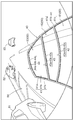
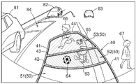
- FIG. 4 is a view showing an example of the surrounding image and the predicted course line 40 displayed on the monitor 20.
- the vehicle 30 is moved backward and parallel parking is performed in the parking space 84 between the parking vehicles 81 and 82.
- the traveling vehicle 83 is a vehicle traveling on the opposite lane.
- Such an image can be used not only for the vehicle periphery monitoring device but also for the parking assistance device.
- the predicted track line 40 includes a pair of predicted track lines 41 on the left and right that indicate the predicted track of the vehicle 30 and a distance reference line 42, 43 and 44.
- the distance reference lines 42, 43 and 44 indicate positions of 0.5 m, 1.0 m and 2.2 m from the rear end of the vehicle 30, respectively.
- the predicted track line 40 is basically drawn in yellow, but the distance reference line 42 and the predicted track line 41 on the side of the vehicle 30 from this are displayed in red in order to call the driver's attention.
- the color of the predicted course line 40, the number of the distance reference lines, the position, and the like are not limited to the above.
- the predicted course line 40 may be displayed not by a solid line but by a dotted line, a broken line or a dashed line.
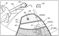
- the predicted trajectory line 41 is composed of a main line portion 41a, a side surface portion 41b and a shadowed portion 41c.
- the side surface portion 41b and the shadowed portion 41c are attached to the inner side in the vehicle width direction of the main line portion 41a.
- the distance reference lines 42, 43 and 44 are respectively constituted by main line portions 42a, 43a and 44a, side portions 42b, 43b and 44b attached to the vehicle 30 side, and shadowed portions 42c, 43c and 44c.
- the predicted course line 40 is three-dimensionally displayed by attaching the side portions 41b, 42b, 43b, 44b and the shadowed portions 41c, 42c, 43c, 44c, and the driver intuitively senses the distance to the obstacle. It becomes easy to grasp.
- the predicted track line 40 changes in accordance with the traveling state detected by the traveling state detection unit 6. For example, when the steering 24 is steered, the forecasted course line 40 moves left and right on the monitor 20 in conjunction with this. If an area defined by the left and right predicted locus lines 41 and the distance reference line 44 farthest from the vehicle 30 among the predicted track lines 40 is set as a predicted track area 50 and an obstacle is present in the predicted track area 50, Highlight a partial area that includes the obstacle. In the present embodiment, it is determined whether or not to highlight each of the areas 51, 52 and 53 obtained by dividing the predicted track area 50 into three in the perspective direction by the distance reference lines 42 and 43.
- an obstacle is a concept including a person.
- the areas 51 and 53 are highlighted.
- highlighting is performed by filling the area 51 with translucent red and filling the area 53 with translucent green.
- the area 52 where the obstacles 63 and 64 are present is filled with translucent yellow
- the area 53 where the obstacles 65 and 66 are present is filled with translucent green.
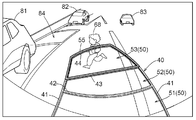
- the driver refers to the predicted track line 40 so that the driver can see the vehicle and obstacles. It is easy to grasp the sense of distance intuitively. Further, since the predicted course line 40 displayed on the monitor 20 is linked to the steering of the steering 24, it is easy to determine whether or not the obstacle can be avoided by the steering of the steering 24.
- the highlighted range becomes wider compared to the case where the obstacle itself is highlighted, so that the driver The presence of an object can be easily recognized by the monitor 20.
- the color of the fill is red
- the area 51 close to the vehicle 30 is in a strong sense of imminent warning
- the area 53 far from the vehicle 30 is pale green in color
- the middle area 52 is yellow.
- the peripheral image acquired by the image acquisition unit 1 is also displayed on the monitor 20, the peripheral image can be viewed as the background of the filled area by making the filling semi-transparent. For this reason, the driver can recognize the obstacle shown in the peripheral image, and the obstacle can be easily avoided.
- the vehicle 30 has a parking assistance function, it is also possible to make the predicted course line 40 the same as the index line displayed for parking assistance.
- the driver can easily become familiar with the predicted track line 40 by using the predicted track line 40 with a plurality of functions, and grasp the perspective of the highlighted area with reference to the predicted track line 40. Becomes easy.
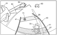
- FIG. 7 shows an example in which the outline 55 of the area 53 where the obstacle 68 is present is highlighted.
- the contour 55 is composed of distance reference lines 43 and 44 and a part of a predicted trajectory line 41 extending between them.
- the outline 55 may be filled with a specific color, displayed in a blinking manner, displayed as a thick line, or the like.
- the predicted track area 50 also includes the predicted track 40
- the area 56 points to the side closer to the obstacle 69 (in this example, the left side in FIG. 8) among the parts of the predicted trajectory line 41 that forms the outline of the area 52 including the obstacle 69.
- the area 56 may be filled with a specific color, blinked, displayed as a thick line, or the like.
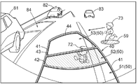
- FIG. 9 shows an example in which the predicted track line 40 does not have a distance reference line and is constituted only by the predicted track line 41.
- highlighting is performed by filling the areas 57 and 58, but the outline of the areas 57 and 58 may be highlighted.
- FIG. 11 In addition to the highlighting of the area
- the highlighting of the obstacles 73 and 74 is not limited to the filling, and other means such as a frame may be employed.
- the outline of the obstacle may be detected by image processing or the like, and the inside of the outline may not be filled.
- an obstacle may be detected by a frame, and the inside of the frame may not be filled.
- the predicted course line 40 may not be displayed partially. According to these configurations, it is easier for the driver to recognize an obstacle on the monitor 20.
- the predicted travel area 50 in the left-right direction (vehicle width direction), and the predicted travel line 40 does not have to be linked to the steering of the steering 24 and the state at a certain point It may be fixed by Further, it is possible to configure the vehicle periphery monitoring device in which the driver can intuitively grasp the sense of distance to the obstacle existing in front of the vehicle 30 by attaching the camera 12 and the sonar 13 to the front of the vehicle 30 . Furthermore, a camera 12 and a sonar 13 are attached to at least one of the left and right side portions of the vehicle 30 so that the driver can intuitively grasp the sense of distance to an obstacle present on the side of the vehicle 30 It is also possible to configure.
- the present invention can be applied to a vehicle periphery monitoring device for highlighting an obstacle on a display device provided in a vehicle cabin to alert the driver.
Landscapes
- Engineering & Computer Science (AREA)
- Physics & Mathematics (AREA)
- General Physics & Mathematics (AREA)
- Mechanical Engineering (AREA)
- Multimedia (AREA)
- Chemical & Material Sciences (AREA)
- Combustion & Propulsion (AREA)
- Transportation (AREA)
- Traffic Control Systems (AREA)
- Closed-Circuit Television Systems (AREA)
- Fittings On The Vehicle Exterior For Carrying Loads, And Devices For Holding Or Mounting Articles (AREA)
Priority Applications (3)
| Application Number | Priority Date | Filing Date | Title |
|---|---|---|---|
| US13/516,128 US8793053B2 (en) | 2010-01-19 | 2010-12-21 | Vehicle periphery monitoring device |
| EP10843976.1A EP2528330B1 (en) | 2010-01-19 | 2010-12-21 | Vehicle periphery monitoring device |
| CN201080059719.2A CN102696225B (zh) | 2010-01-19 | 2010-12-21 | 车辆周边监视装置 |
Applications Claiming Priority (2)
| Application Number | Priority Date | Filing Date | Title |
|---|---|---|---|
| JP2010-009246 | 2010-01-19 | ||
| JP2010009246A JP5071743B2 (ja) | 2010-01-19 | 2010-01-19 | 車両周辺監視装置 |
Publications (1)
| Publication Number | Publication Date |
|---|---|
| WO2011089812A1 true WO2011089812A1 (ja) | 2011-07-28 |
Family
ID=44306628
Family Applications (1)
| Application Number | Title | Priority Date | Filing Date |
|---|---|---|---|
| PCT/JP2010/072973 Ceased WO2011089812A1 (ja) | 2010-01-19 | 2010-12-21 | 車両周辺監視装置 |
Country Status (5)
| Country | Link |
|---|---|
| US (1) | US8793053B2 (enExample) |
| EP (1) | EP2528330B1 (enExample) |
| JP (1) | JP5071743B2 (enExample) |
| CN (1) | CN102696225B (enExample) |
| WO (1) | WO2011089812A1 (enExample) |
Cited By (6)
| Publication number | Priority date | Publication date | Assignee | Title |
|---|---|---|---|---|
| FR2979300A1 (fr) * | 2011-08-31 | 2013-03-01 | Peugeot Citroen Automobiles Sa | Dispositif pour estimer une trajectoire future d'un vehicule et associer a des parties qu'elle comprend des aspects differents selon leurs positions par rapport a un obstacle, pour un systeme d'aide a la conduite |
| FR2979311A1 (fr) * | 2011-08-31 | 2013-03-01 | Peugeot Citroen Automobiles Sa | Dispositif de traitement pour associer a un element graphique une couleur en fonction d'un niveau de risque de collision d'un obstacle avec une trajectoire future d'un vehicule, pour un systeme d'aide a la conduite |
| FR2979299A1 (fr) * | 2011-08-31 | 2013-03-01 | Peugeot Citroen Automobiles Sa | Dispositif de traitement pour estimer une trajectoire future d'un vehicule, associee a une couleur fonction d'un niveau de risque de collision estime, pour un systeme d'aide a la conduite |
| JP5909289B2 (ja) * | 2012-12-12 | 2016-04-26 | 本田技研工業株式会社 | 駐車スペース検出装置 |
| JP2017138660A (ja) * | 2016-02-01 | 2017-08-10 | トヨタ自動車株式会社 | 物体検出方法、物体検出装置、およびプログラム |
| JP2024129548A (ja) * | 2023-03-13 | 2024-09-27 | 株式会社慶洋エンジニアリング | 後方物体確認装置及び後方物体確認システム |
Families Citing this family (72)
| Publication number | Priority date | Publication date | Assignee | Title |
|---|---|---|---|---|
| JP2011234031A (ja) * | 2010-04-26 | 2011-11-17 | Kyocera Corp | 車載用撮像装置 |
| US20120016555A1 (en) * | 2010-07-18 | 2012-01-19 | Maher Ghneim | Method and system for parking assist |
| US8665116B2 (en) | 2010-07-18 | 2014-03-04 | Ford Global Technologies | Parking assist overlay with variable brightness intensity |
| JP5459154B2 (ja) * | 2010-09-15 | 2014-04-02 | トヨタ自動車株式会社 | 車両用周囲画像表示装置及び方法 |
| US9396401B2 (en) | 2011-11-01 | 2016-07-19 | Aisin Seiki Kabushiki Kaisha | Obstacle alarm device |
| JP5674071B2 (ja) * | 2011-11-01 | 2015-02-25 | アイシン精機株式会社 | 障害物警報装置 |
| EP2775467A4 (en) | 2011-11-01 | 2016-09-28 | Aisin Seiki | ALARM DEVICE FOR OBSTACLES |
| WO2013065122A1 (ja) * | 2011-11-01 | 2013-05-10 | アイシン精機株式会社 | 障害物警報装置 |
| JP5821622B2 (ja) * | 2011-12-26 | 2015-11-24 | アイシン精機株式会社 | 障害物警報装置 |
| JP5747847B2 (ja) * | 2012-03-14 | 2015-07-15 | トヨタ自動車株式会社 | 車両周辺監視装置 |
| CN102848980A (zh) * | 2012-10-11 | 2013-01-02 | 南京艾酷派物联网有限公司 | 环境泊车安全辅助装置 |
| US8885756B1 (en) * | 2012-10-15 | 2014-11-11 | Maritime Telecommunications Network Inc. | Multi-antenna/multilink diversity management for mobile communication platform |
| GB2546187B (en) * | 2013-01-28 | 2017-11-01 | Jaguar Land Rover Ltd | Vehicle path prediction and obstacle indication system and method |
| JP6123133B2 (ja) * | 2013-03-04 | 2017-05-10 | パナソニックIpマネジメント株式会社 | 車両用障害物検知装置および、車両用障害物検知システム |
| JP2014204361A (ja) * | 2013-04-08 | 2014-10-27 | 株式会社ビートソニック | 車載モニタリングシステムにおける車載カメラ用アダプター |
| JP2015008453A (ja) * | 2013-05-29 | 2015-01-15 | 京セラ株式会社 | カメラ装置および警告方法 |
| JP6232759B2 (ja) * | 2013-06-07 | 2017-11-22 | ソニー株式会社 | 情報処理装置、接近対象物通知方法及びプログラム |
| CN105580358B (zh) * | 2013-09-27 | 2017-07-07 | 日产自动车株式会社 | 信息提示系统 |
| JP6134668B2 (ja) * | 2014-02-18 | 2017-05-24 | 日立建機株式会社 | 作業車両の障害物検知装置 |
| DE102014003784A1 (de) * | 2014-03-15 | 2015-09-17 | Audi Ag | Verfahren zur Fahrerinformation in einem Kraftfahrzeug |
| JP6252316B2 (ja) * | 2014-03-31 | 2017-12-27 | 株式会社デンソー | 車両用表示制御装置 |
| JP5933004B2 (ja) | 2014-04-25 | 2016-06-08 | 株式会社小松製作所 | 周辺監視システム、作業車両、及び周辺監視方法 |
| JP6307383B2 (ja) * | 2014-08-07 | 2018-04-04 | 日立オートモティブシステムズ株式会社 | 行動計画装置 |
| WO2016084149A1 (ja) * | 2014-11-26 | 2016-06-02 | 三菱電機株式会社 | 運転支援装置および運転支援方法 |
| DE102015201317B4 (de) * | 2015-01-27 | 2025-03-20 | Bayerische Motoren Werke Aktiengesellschaft | Vermessen einer Abmessung auf einer Oberfläche |
| JP6437091B2 (ja) * | 2015-03-12 | 2018-12-12 | 三菱電機株式会社 | 車群管理装置、車群管理方法、車群管理プログラム及び車群表示装置 |
| DE102015216881A1 (de) * | 2015-09-03 | 2017-03-09 | Robert Bosch Gmbh | Verfahren und Vorrichtung zum fahrerlosen Führen eines Kraftfahrzeugs innerhalb eines Parkplatzes |
| US9873428B2 (en) * | 2015-10-27 | 2018-01-23 | Ford Global Technologies, Llc | Collision avoidance using auditory data |
| JP6601679B2 (ja) * | 2016-03-01 | 2019-11-06 | パナソニックIpマネジメント株式会社 | 判定装置、判定方法、および判定プログラム |
| CN108027423B (zh) * | 2016-03-14 | 2022-01-04 | 日立建机株式会社 | 矿山用作业机械 |
| CN108885839A (zh) * | 2016-03-31 | 2018-11-23 | 古河电气工业株式会社 | 监视装置和监视方法 |
| DE112016006740B4 (de) * | 2016-04-15 | 2019-09-12 | Mitsubishi Electric Corporation | Parkassistenzvorrichtung |
| JP6595401B2 (ja) * | 2016-04-26 | 2019-10-23 | 株式会社Soken | 表示制御装置 |
| JP6390035B2 (ja) * | 2016-05-23 | 2018-09-19 | 本田技研工業株式会社 | 車両制御システム、車両制御方法、および車両制御プログラム |
| CN107640147B (zh) * | 2016-07-18 | 2020-12-04 | 奥迪股份公司 | 泊车辅助方法和系统 |
| JP6776702B2 (ja) * | 2016-07-29 | 2020-10-28 | アイシン精機株式会社 | 周辺監視装置 |
| WO2018037789A1 (ja) * | 2016-08-22 | 2018-03-01 | ソニー株式会社 | 画像処理装置、および画像処理方法、並びにプログラム |
| JP6776058B2 (ja) * | 2016-08-26 | 2020-10-28 | シャープ株式会社 | 自律走行車両制御装置、自律走行車両制御システム及び自律走行車両制御方法 |
| FR3055870B1 (fr) * | 2016-09-15 | 2019-09-27 | Renault S.A.S. | Methode d'aide a la conduite, procede d'implementation d'une telle methode et dispositif d'aide a la conduite |
| CN109983305A (zh) * | 2016-11-25 | 2019-07-05 | 本田技研工业株式会社 | 车辆用显示控制装置、车辆用显示控制方法及车辆用显示控制程序 |
| EP3554062B1 (en) | 2016-12-09 | 2022-12-14 | Kyocera Corporation | Imaging apparatus |
| JP6974564B2 (ja) * | 2016-12-09 | 2021-12-01 | 京セラ株式会社 | 表示制御装置 |
| JP6565893B2 (ja) * | 2016-12-26 | 2019-08-28 | トヨタ自動車株式会社 | 運転支援装置 |
| JP2018110328A (ja) | 2017-01-04 | 2018-07-12 | 株式会社デンソーテン | 画像処理装置および画像処理方法 |
| FR3061780B1 (fr) * | 2017-01-12 | 2022-08-19 | Valeo Schalter & Sensoren Gmbh | Procede de pilotage d'un afficheur de vehicule automobile, et afficheur correspondant |
| CN110537213B (zh) * | 2017-04-24 | 2021-08-03 | 三菱电机株式会社 | 通知控制装置及通知控制方法 |
| JP6760210B2 (ja) * | 2017-06-16 | 2020-09-23 | 株式会社Jvcケンウッド | 表示制御装置、表示制御システム、表示制御方法及び表示制御プログラム |
| JP6760211B2 (ja) * | 2017-06-16 | 2020-09-23 | 株式会社Jvcケンウッド | 表示制御装置、表示制御システム、表示制御方法及び表示制御プログラム |
| WO2018230021A1 (ja) | 2017-06-16 | 2018-12-20 | 株式会社Jvcケンウッド | 表示制御装置、表示制御システム、表示制御方法及び表示制御プログラム |
| CN110914882B (zh) * | 2017-07-05 | 2022-02-08 | 三菱电机株式会社 | 显示系统和显示方法 |
| JP6741364B2 (ja) | 2017-08-03 | 2020-08-19 | 三菱電機株式会社 | 車両周辺画像表示装置および車両周辺画像表示方法 |
| JP6555599B2 (ja) * | 2017-08-04 | 2019-08-07 | 本田技研工業株式会社 | 表示システム、表示方法、およびプログラム |
| DE102017215519A1 (de) | 2017-09-05 | 2019-03-07 | Robert Bosch Gmbh | Verfahren und Vorrichtung zur Kollisionserkennung für ein Fahrzeug |
| CN110843910A (zh) * | 2018-08-21 | 2020-02-28 | 上海博泰悦臻网络技术服务有限公司 | 车辆拐弯控制装置及方法 |
| JP7088807B2 (ja) * | 2018-10-29 | 2022-06-21 | 京セラ株式会社 | 画像処理装置、カメラ、移動体および画像処理方法 |
| KR20200056497A (ko) * | 2018-11-09 | 2020-05-25 | 현대자동차주식회사 | 자율 발렛 주차를 지원하는 시스템 및 방법, 그리고 이를 위한 인프라 및 차량 |
| CN109774618A (zh) * | 2019-01-23 | 2019-05-21 | 钟辉 | 一种无盲区的车载影像系统及其显示方法 |
| CN109901575A (zh) * | 2019-02-20 | 2019-06-18 | 百度在线网络技术(北京)有限公司 | 车辆路线规划调试方法、装置、设备及计算机可读介质 |
| JP2020154369A (ja) * | 2019-03-18 | 2020-09-24 | 株式会社Jvcケンウッド | 障害物情報管理装置、障害物情報管理方法、及び障害物情報管理プログラム |
| JP7209189B2 (ja) * | 2019-03-25 | 2023-01-20 | パナソニックIpマネジメント株式会社 | 画像生成装置、カメラ、表示システム、車両及び画像生成方法 |
| JP7259698B2 (ja) * | 2019-10-17 | 2023-04-18 | トヨタ自動車株式会社 | 自動駐車システム |
| JP7284458B2 (ja) * | 2019-10-17 | 2023-05-31 | 三菱自動車工業株式会社 | 駐車支援装置 |
| CN115315738A (zh) * | 2020-03-26 | 2022-11-08 | 日产自动车株式会社 | 信息提供方法、车辆系统以及管理装置 |
| JP7007438B2 (ja) * | 2020-09-09 | 2022-01-24 | 京セラ株式会社 | 撮像装置、画像処理装置、表示装置、表示システム、および車両 |
| CN115139899B (zh) * | 2021-03-30 | 2024-06-25 | 三菱物捷仕株式会社 | 车辆接近告知装置及包括所述装置的拣货堆高机 |
| DE102021126950A1 (de) | 2021-10-18 | 2023-04-20 | Bayerische Motoren Werke Aktiengesellschaft | Steuerverfahren und steuervorrichtung für eine anzeigevorrichtung in einem kraftfahrzeuginnenraum |
| US20230256985A1 (en) * | 2022-02-14 | 2023-08-17 | Continental Advanced Lidar Solutions Us, Llc | Method and system for avoiding vehicle undercarriage collisions |
| US12097870B2 (en) | 2022-09-07 | 2024-09-24 | Toyota Motor Engineering & Manufacturing North America, Inc. | Intuitive two-dimensional warning indicator systems and methods |
| EP4588029A1 (en) * | 2022-09-16 | 2025-07-23 | Indian Motorcycle International, LLC | Vehicle proximity display on user interface |
| CN115991205A (zh) * | 2022-12-23 | 2023-04-21 | 博泰车联网科技(上海)股份有限公司 | 基于雷达监测激活全景影像的方法、系统及存储介质 |
| US20240424896A1 (en) * | 2023-06-23 | 2024-12-26 | Deere & Company | Work vehicle having speed and/or distance based decision support and intervention zones |
| CN119459523B (zh) * | 2024-12-13 | 2025-10-10 | 奇瑞汽车股份有限公司 | 一种车前全景影像显示方法、系统、存储介质和电子设备 |
Citations (8)
| Publication number | Priority date | Publication date | Assignee | Title |
|---|---|---|---|---|
| JPH07223488A (ja) | 1994-02-14 | 1995-08-22 | Mitsubishi Motors Corp | 車両用周囲情報表示装置 |
| JPH10117340A (ja) * | 1996-10-11 | 1998-05-06 | Yazaki Corp | 車両周辺監視装置、この装置に用いられる警報表示方法、及びこの表示方法を記憶した媒体 |
| JP2000177513A (ja) * | 1998-12-16 | 2000-06-27 | Toyota Autom Loom Works Ltd | 車両における後退支援装置及び車両 |
| JP2002029346A (ja) * | 2000-07-14 | 2002-01-29 | Hiroyuki Yokozawa | 自動車の運転支援システム及び運転支援プログラムを記録した記録媒体 |
| JP2004203068A (ja) * | 2002-12-24 | 2004-07-22 | Aisin Seiki Co Ltd | 移動体周辺監視装置 |
| JP2009040108A (ja) | 2007-08-06 | 2009-02-26 | Denso Corp | 画像表示制御装置及び画像表示制御システム |
| JP2009265803A (ja) * | 2008-04-23 | 2009-11-12 | Panasonic Corp | 車両視界支援装置 |
| JP2009292457A (ja) * | 2008-05-08 | 2009-12-17 | Aisin Seiki Co Ltd | 車両周辺表示装置 |
Family Cites Families (3)
| Publication number | Priority date | Publication date | Assignee | Title |
|---|---|---|---|---|
| US6411867B1 (en) * | 1999-10-27 | 2002-06-25 | Fujitsu Ten Limited | Vehicle driving support system, and steering angle detection device |
| JP3645196B2 (ja) * | 2001-02-09 | 2005-05-11 | 松下電器産業株式会社 | 画像合成装置 |
| JP4404103B2 (ja) * | 2007-03-22 | 2010-01-27 | 株式会社デンソー | 車両外部撮影表示システムおよび画像表示制御装置 |
-
2010
- 2010-01-19 JP JP2010009246A patent/JP5071743B2/ja active Active
- 2010-12-21 CN CN201080059719.2A patent/CN102696225B/zh active Active
- 2010-12-21 EP EP10843976.1A patent/EP2528330B1/en active Active
- 2010-12-21 WO PCT/JP2010/072973 patent/WO2011089812A1/ja not_active Ceased
- 2010-12-21 US US13/516,128 patent/US8793053B2/en active Active
Patent Citations (8)
| Publication number | Priority date | Publication date | Assignee | Title |
|---|---|---|---|---|
| JPH07223488A (ja) | 1994-02-14 | 1995-08-22 | Mitsubishi Motors Corp | 車両用周囲情報表示装置 |
| JPH10117340A (ja) * | 1996-10-11 | 1998-05-06 | Yazaki Corp | 車両周辺監視装置、この装置に用いられる警報表示方法、及びこの表示方法を記憶した媒体 |
| JP2000177513A (ja) * | 1998-12-16 | 2000-06-27 | Toyota Autom Loom Works Ltd | 車両における後退支援装置及び車両 |
| JP2002029346A (ja) * | 2000-07-14 | 2002-01-29 | Hiroyuki Yokozawa | 自動車の運転支援システム及び運転支援プログラムを記録した記録媒体 |
| JP2004203068A (ja) * | 2002-12-24 | 2004-07-22 | Aisin Seiki Co Ltd | 移動体周辺監視装置 |
| JP2009040108A (ja) | 2007-08-06 | 2009-02-26 | Denso Corp | 画像表示制御装置及び画像表示制御システム |
| JP2009265803A (ja) * | 2008-04-23 | 2009-11-12 | Panasonic Corp | 車両視界支援装置 |
| JP2009292457A (ja) * | 2008-05-08 | 2009-12-17 | Aisin Seiki Co Ltd | 車両周辺表示装置 |
Non-Patent Citations (1)
| Title |
|---|
| See also references of EP2528330A4 |
Cited By (10)
| Publication number | Priority date | Publication date | Assignee | Title |
|---|---|---|---|---|
| FR2979300A1 (fr) * | 2011-08-31 | 2013-03-01 | Peugeot Citroen Automobiles Sa | Dispositif pour estimer une trajectoire future d'un vehicule et associer a des parties qu'elle comprend des aspects differents selon leurs positions par rapport a un obstacle, pour un systeme d'aide a la conduite |
| FR2979311A1 (fr) * | 2011-08-31 | 2013-03-01 | Peugeot Citroen Automobiles Sa | Dispositif de traitement pour associer a un element graphique une couleur en fonction d'un niveau de risque de collision d'un obstacle avec une trajectoire future d'un vehicule, pour un systeme d'aide a la conduite |
| FR2979299A1 (fr) * | 2011-08-31 | 2013-03-01 | Peugeot Citroen Automobiles Sa | Dispositif de traitement pour estimer une trajectoire future d'un vehicule, associee a une couleur fonction d'un niveau de risque de collision estime, pour un systeme d'aide a la conduite |
| WO2013030480A1 (fr) * | 2011-08-31 | 2013-03-07 | Peugeot Citroen Automobiles Sa | Dispositif pour estimer une trajectoire future d'un véhicule et associer à des parties qu'elle comprend des aspects différents selon leurs positions par rapport à un obstacle, pour un système d'aide à la conduite |
| CN103764485A (zh) * | 2011-08-31 | 2014-04-30 | 标致·雪铁龙汽车公司 | 用于驾驶辅助系统的用于估算运输工具的未来路线并且与部件相关联的装置,所述未来路线包括根据相对于障碍物位置的不同外观 |
| CN103764485B (zh) * | 2011-08-31 | 2016-06-22 | 标致·雪铁龙汽车公司 | 用于驾驶辅助系统的装置 |
| JP5909289B2 (ja) * | 2012-12-12 | 2016-04-26 | 本田技研工業株式会社 | 駐車スペース検出装置 |
| JP2017138660A (ja) * | 2016-02-01 | 2017-08-10 | トヨタ自動車株式会社 | 物体検出方法、物体検出装置、およびプログラム |
| JP2024129548A (ja) * | 2023-03-13 | 2024-09-27 | 株式会社慶洋エンジニアリング | 後方物体確認装置及び後方物体確認システム |
| JP7611282B2 (ja) | 2023-03-13 | 2025-01-09 | 株式会社慶洋エンジニアリング | 後方物体確認装置及び後方物体確認システム |
Also Published As
| Publication number | Publication date |
|---|---|
| JP2011151479A (ja) | 2011-08-04 |
| EP2528330B1 (en) | 2020-03-25 |
| EP2528330A4 (en) | 2016-11-30 |
| US20120296523A1 (en) | 2012-11-22 |
| CN102696225A (zh) | 2012-09-26 |
| CN102696225B (zh) | 2014-10-08 |
| US8793053B2 (en) | 2014-07-29 |
| EP2528330A1 (en) | 2012-11-28 |
| JP5071743B2 (ja) | 2012-11-14 |
Similar Documents
| Publication | Publication Date | Title |
|---|---|---|
| JP5071743B2 (ja) | 車両周辺監視装置 | |
| JP2011151479A5 (enExample) | ||
| JP6806156B2 (ja) | 周辺監視装置 | |
| JP5636609B2 (ja) | 車両周辺表示装置 | |
| JP5454934B2 (ja) | 運転支援装置 | |
| JP6387369B2 (ja) | 走行制御装置 | |
| JP6897340B2 (ja) | 周辺監視装置 | |
| US8384561B2 (en) | Parking assist device | |
| JP4623395B2 (ja) | 車両周辺表示装置 | |
| JP6281289B2 (ja) | 周辺監視装置、及びプログラム | |
| JP5991112B2 (ja) | 駐車支援装置、制御方法、およびプログラム | |
| CN112644512A (zh) | 车辆警报装置 | |
| JP2017094922A (ja) | 周辺監視装置 | |
| JP2014069721A (ja) | 周辺監視装置、制御方法、及びプログラム | |
| JP2018207289A (ja) | 周辺表示装置 | |
| JP2012066615A (ja) | 運転支援装置 | |
| JP6606956B2 (ja) | 周辺監視装置 | |
| JP2013135316A (ja) | 障害物警報装置 | |
| JP6953915B2 (ja) | 周辺監視装置 |
Legal Events
| Date | Code | Title | Description |
|---|---|---|---|
| 121 | Ep: the epo has been informed by wipo that ep was designated in this application |
Ref document number: 10843976 Country of ref document: EP Kind code of ref document: A1 |
|
| WWE | Wipo information: entry into national phase |
Ref document number: 2010843976 Country of ref document: EP |
|
| WWE | Wipo information: entry into national phase |
Ref document number: 13516128 Country of ref document: US |
|
| NENP | Non-entry into the national phase |
Ref country code: DE |