WO2011089812A1 - 車両周辺監視装置 - Google Patents
車両周辺監視装置 Download PDFInfo
- Publication number
- WO2011089812A1 WO2011089812A1 PCT/JP2010/072973 JP2010072973W WO2011089812A1 WO 2011089812 A1 WO2011089812 A1 WO 2011089812A1 JP 2010072973 W JP2010072973 W JP 2010072973W WO 2011089812 A1 WO2011089812 A1 WO 2011089812A1
- Authority
- WO
- WIPO (PCT)
- Prior art keywords
- vehicle
- obstacle
- predicted
- monitoring device
- area
- Prior art date
Links
- 238000012806 monitoring device Methods 0.000 title claims abstract description 21
- 238000001514 detection method Methods 0.000 claims abstract description 19
- 230000002093 peripheral effect Effects 0.000 claims description 12
- 238000003384 imaging method Methods 0.000 claims description 9
- 238000013459 approach Methods 0.000 claims description 2
- 239000003973 paint Substances 0.000 claims 1
- 238000010586 diagram Methods 0.000 description 4
- 238000000034 method Methods 0.000 description 3
- 238000012544 monitoring process Methods 0.000 description 2
- 230000005540 biological transmission Effects 0.000 description 1
- 230000004397 blinking Effects 0.000 description 1
- 230000001939 inductive effect Effects 0.000 description 1
- 238000005259 measurement Methods 0.000 description 1
- 238000012545 processing Methods 0.000 description 1
- 230000000007 visual effect Effects 0.000 description 1
Images


Classifications
-
- B—PERFORMING OPERATIONS; TRANSPORTING
- B60—VEHICLES IN GENERAL
- B60R—VEHICLES, VEHICLE FITTINGS, OR VEHICLE PARTS, NOT OTHERWISE PROVIDED FOR
- B60R1/00—Optical viewing arrangements; Real-time viewing arrangements for drivers or passengers using optical image capturing systems, e.g. cameras or video systems specially adapted for use in or on vehicles
- B60R1/20—Real-time viewing arrangements for drivers or passengers using optical image capturing systems, e.g. cameras or video systems specially adapted for use in or on vehicles
- B60R1/22—Real-time viewing arrangements for drivers or passengers using optical image capturing systems, e.g. cameras or video systems specially adapted for use in or on vehicles for viewing an area outside the vehicle, e.g. the exterior of the vehicle
- B60R1/23—Real-time viewing arrangements for drivers or passengers using optical image capturing systems, e.g. cameras or video systems specially adapted for use in or on vehicles for viewing an area outside the vehicle, e.g. the exterior of the vehicle with a predetermined field of view
- B60R1/26—Real-time viewing arrangements for drivers or passengers using optical image capturing systems, e.g. cameras or video systems specially adapted for use in or on vehicles for viewing an area outside the vehicle, e.g. the exterior of the vehicle with a predetermined field of view to the rear of the vehicle
-
- B—PERFORMING OPERATIONS; TRANSPORTING
- B62—LAND VEHICLES FOR TRAVELLING OTHERWISE THAN ON RAILS
- B62D—MOTOR VEHICLES; TRAILERS
- B62D15/00—Steering not otherwise provided for
- B62D15/02—Steering position indicators ; Steering position determination; Steering aids
- B62D15/027—Parking aids, e.g. instruction means
- B62D15/0275—Parking aids, e.g. instruction means by overlaying a vehicle path based on present steering angle over an image without processing that image
-
- G—PHYSICS
- G08—SIGNALLING
- G08G—TRAFFIC CONTROL SYSTEMS
- G08G1/00—Traffic control systems for road vehicles
- G08G1/16—Anti-collision systems
- G08G1/166—Anti-collision systems for active traffic, e.g. moving vehicles, pedestrians, bikes
-
- G—PHYSICS
- G08—SIGNALLING
- G08G—TRAFFIC CONTROL SYSTEMS
- G08G1/00—Traffic control systems for road vehicles
- G08G1/16—Anti-collision systems
- G08G1/168—Driving aids for parking, e.g. acoustic or visual feedback on parking space
-
- B—PERFORMING OPERATIONS; TRANSPORTING
- B60—VEHICLES IN GENERAL
- B60R—VEHICLES, VEHICLE FITTINGS, OR VEHICLE PARTS, NOT OTHERWISE PROVIDED FOR
- B60R2300/00—Details of viewing arrangements using cameras and displays, specially adapted for use in a vehicle
- B60R2300/30—Details of viewing arrangements using cameras and displays, specially adapted for use in a vehicle characterised by the type of image processing
- B60R2300/301—Details of viewing arrangements using cameras and displays, specially adapted for use in a vehicle characterised by the type of image processing combining image information with other obstacle sensor information, e.g. using RADAR/LIDAR/SONAR sensors for estimating risk of collision
-
- B—PERFORMING OPERATIONS; TRANSPORTING
- B60—VEHICLES IN GENERAL
- B60R—VEHICLES, VEHICLE FITTINGS, OR VEHICLE PARTS, NOT OTHERWISE PROVIDED FOR
- B60R2300/00—Details of viewing arrangements using cameras and displays, specially adapted for use in a vehicle
- B60R2300/30—Details of viewing arrangements using cameras and displays, specially adapted for use in a vehicle characterised by the type of image processing
- B60R2300/307—Details of viewing arrangements using cameras and displays, specially adapted for use in a vehicle characterised by the type of image processing virtually distinguishing relevant parts of a scene from the background of the scene
-
- B—PERFORMING OPERATIONS; TRANSPORTING
- B60—VEHICLES IN GENERAL
- B60R—VEHICLES, VEHICLE FITTINGS, OR VEHICLE PARTS, NOT OTHERWISE PROVIDED FOR
- B60R2300/00—Details of viewing arrangements using cameras and displays, specially adapted for use in a vehicle
- B60R2300/80—Details of viewing arrangements using cameras and displays, specially adapted for use in a vehicle characterised by the intended use of the viewing arrangement
- B60R2300/806—Details of viewing arrangements using cameras and displays, specially adapted for use in a vehicle characterised by the intended use of the viewing arrangement for aiding parking
-
- B—PERFORMING OPERATIONS; TRANSPORTING
- B60—VEHICLES IN GENERAL
- B60R—VEHICLES, VEHICLE FITTINGS, OR VEHICLE PARTS, NOT OTHERWISE PROVIDED FOR
- B60R2300/00—Details of viewing arrangements using cameras and displays, specially adapted for use in a vehicle
- B60R2300/80—Details of viewing arrangements using cameras and displays, specially adapted for use in a vehicle characterised by the intended use of the viewing arrangement
- B60R2300/8066—Details of viewing arrangements using cameras and displays, specially adapted for use in a vehicle characterised by the intended use of the viewing arrangement for monitoring rearward traffic
-
- B—PERFORMING OPERATIONS; TRANSPORTING
- B60—VEHICLES IN GENERAL
- B60R—VEHICLES, VEHICLE FITTINGS, OR VEHICLE PARTS, NOT OTHERWISE PROVIDED FOR
- B60R2300/00—Details of viewing arrangements using cameras and displays, specially adapted for use in a vehicle
- B60R2300/80—Details of viewing arrangements using cameras and displays, specially adapted for use in a vehicle characterised by the intended use of the viewing arrangement
- B60R2300/8093—Details of viewing arrangements using cameras and displays, specially adapted for use in a vehicle characterised by the intended use of the viewing arrangement for obstacle warning
Definitions
- the present invention relates to a vehicle periphery monitoring device for highlighting an obstacle on a display device provided in a vehicle cabin to alert a driver.
- Patent Document 1 an apparatus of this type is known. This is to extract an obstacle existing around the vehicle based on a signal obtained from an imaging device for imaging the periphery of the vehicle and display the obstacle on the display device. By changing the display method of the obstacle according to the degree of danger determined by the attribute of the obstacle and the moving direction, etc., the driver can recognize the positional relationship between the own vehicle and the obstacle and the degree of danger There is.
- the vehicle surrounding information display device described in Patent Document 2 displays the obstacle detected by the vehicle surrounding object detecting means by adding risk information to a schematic picture display set in advance.
- the driver can easily grasp the situation around the vehicle by setting the perspective display level of the basic image indicating the surrounding situation that is the background when displaying the obstacle. It is configured.
- Each of the apparatuses described in Patent Documents 1 and 2 adopts a form in which information about the degree of risk is added to the obstacle itself and displayed. Therefore, when a plurality of obstacles exist in the target range, much information may be displayed on the display screen at one time, which may make it difficult for the driver to quickly grasp the surrounding situation. Also, by determining the degree of risk taking into consideration factors other than the distance between the vehicle and the obstacle, such as the attribute and movement direction of the obstacle, the sense of distance to the obstacle displayed on the screen is difficult to grasp Can be considered. Furthermore, it is difficult to intuitively understand whether or not the obstacle can be avoided by the steering operation only by superimposing the obstacle on the surrounding image.
- the present invention has been made in view of the above problems, and a vehicle periphery monitoring device that allows the driver to intuitively grasp the sense of distance between the vehicle and the obstacle without excessive information displayed on the display device. Intended to provide.
- the first characteristic configuration of the vehicle periphery monitoring device includes an image acquisition unit for acquiring an image of the periphery of the vehicle taken by an imaging device provided in the vehicle, an obstacle around the vehicle, and the position thereof.
- a traveling state detection unit that detects the traveling state of the vehicle
- a predicted track line generation unit that generates a predicted track based on the traveling state of the vehicle detected by the traveling state detection unit
- a highlight determining unit configured to determine highlighting of a partial area including the obstacle in the predicted course area when the obstacle is present in the predicted course area defined by the predicted course line
- a display control unit for superimposing the predicted course line and the highlighted display on a peripheral image and displaying the superimposed image on a display device provided in a vehicle compartment of the vehicle.
- the driver can refer to the predicted track by referring to the predicted track. It is easy to intuitively grasp the sense of distance between your own vehicle and an obstacle.
- the obstacle itself is not highlighted individually but the area including the obstacle is highlighted, if there are many obstacles, it is troublesome to be highlighted for each obstacle. Can be avoided.
- the driver can easily recognize the presence of the obstacle because the area including the obstacle is highlighted.
- a second feature configuration is that the highlighting is performed in each of regions obtained by dividing the predicted travel region at least in the perspective direction in advance.
- the highlighting is performed for each of the divided regions in the perspective direction, it is easy to grasp the sense of distance between the highlighted region and the vehicle. Therefore, the driver can easily grasp the distance to the obstacle, and the operation for avoiding the obstacle can be easily performed.
- a third characteristic configuration is that the display control unit displays a side surface portion on the side closer to the imaging device of the predicted course line.
- the predicted course line is three-dimensionally represented, it is easy to grasp the sense of distance between the vehicle and the obstacle with reference to the predicted course line.
- a fourth characteristic configuration is that the display control unit displays a shadowed portion on the side closer to the imaging device of the predicted course line.
- the predicted course line is three-dimensionally represented, it is easy to grasp the sense of distance between the vehicle and the obstacle with reference to the predicted course line.
- the highlighting is performed by filling the partial area.
- the driver when highlighting is performed by filling in the area, the driver can easily recognize the highlighting, so the risk of overlooking an obstacle can be reduced.
- a sixth feature resides in that the fill is translucent.
- the peripheral image to be the background of the highlighting can also be seen through. Therefore, in combination with the highlighting, the obstacle that is actually present can be recognized on the display device. As a result, the positional relationship between the vehicle and the obstacle can be easily grasped, and the operation for avoiding the obstacle can be easily performed.
- a seventh feature lies in that the color of the fill is changed according to the distance between the vehicle and the obstacle.
- the fill color is a reddish color having a warning meaning as the distance to the vehicle is closer, and a green or bluish color as the distance is longer, the self color is selected. It becomes easy to intuitively grasp the distance between the car and the obstacle.
- the eighth feature configuration is that the predicted course line is interlocked with steering of the steering.
- the predicted course area defined by the predicted course line is also interlocked with the steering of the steering. Therefore, even when an obstacle is included in the predicted travel area by steering, the driver highlights the presence of the new obstacle by highlighting the area including the obstacle. It can be easily recognized. In addition, since the predicted travel area moves in conjunction with the steering of the steering, the obstacle avoidance operation becomes easy.
- a ninth characterizing feature is to highlight the obstacle relatively approaching the predicted travel area.
- the driver can easily recognize the presence of the obstacle when the obstacle is relatively approaching the predicted travel area due to the operation of the vehicle or the movement of the obstacle. , It will be easier to avoid obstacles.
- FIG. 1 is a block diagram showing a configuration of a vehicle periphery monitoring device according to the present invention. It is a figure which shows an example of the periphery image displayed on a monitor, and a prediction course line. It is a figure which shows an example of a highlighting. It is a figure which shows an example of a highlighting. It is a figure which shows an example of the highlighting in another embodiment. It is a figure which shows an example of the highlighting in another embodiment. It is a figure which shows an example of the highlighting in another embodiment. It is a figure which shows an example of the highlighting in another embodiment. It is a figure which shows an example of the highlighting in another embodiment. It is a figure which shows an example of the highlighting in another embodiment. It is a figure which shows an example of the highlighting in another embodiment. It is a figure which shows an example of the highlighting in another embodiment. It is a figure which shows an example of the highlighting in another embodiment.
- FIGS. 1 to 6 An embodiment of a vehicle periphery monitoring apparatus according to the present invention will be described with reference to FIGS. 1 to 6.
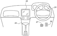
- FIG.1 and FIG.2 is the figure which showed the basic composition of the vehicle 30 provided with the vehicle periphery monitoring apparatus based on this embodiment.
- the steering 24 provided at the driver's seat interlocks with the power steering unit 33, transmits the rotational operation force to the front wheels 28f, and steers the vehicle 30.
- An engine 32 and a transmission mechanism 34 for transmitting power from the engine 32 to the front wheel 28 f and the rear wheel 28 r are disposed at the front of the vehicle 30. Power is transmitted to both or either of the front wheel 28 f and the rear wheel 28 r according to the drive system (front wheel drive, rear wheel drive, four wheel drive) of the vehicle 30.
- an accelerator pedal 26 for controlling the traveling speed and a brake pedal 27 for applying a braking force to the front wheel 28 f and the rear wheel 28 r via the brake device 31 are arranged in parallel.
- a monitor 20 (display device) is provided at an upper position of the console near the driver's seat. In the case of a vehicle 30 provided with a parking assistance device or a navigation system, the monitor 20 may be used also as a display device used for these.
- a steering sensor 14 is provided in the operation system of the steering 24, and the steering direction and the operation amount of the steering 24 are measured.
- a shift position sensor 15 is provided in the operation system of the shift lever 25 to determine the shift position.
- an accelerator sensor 16 is provided in the operation system of the accelerator pedal 26, and a brake sensor 17 is provided in the operation system of the brake pedal 27, and the amount of operation is measured.
- a wheel speed sensor 18 that measures the amount of rotation of the rear wheel 28 r is provided in the vicinity of the rear wheel 28 r. Note that these sensors are not limited to the above configuration, and other configurations may be used as long as substantially the same measurement values can be obtained.
- a camera 12 for shooting an image of a surrounding area behind the vehicle 30 is provided at the center of the rear of the vehicle 30.
- the peripheral image captured by the camera 12 is configured to be displayed on the monitor 20.
- sonars 13 are provided which detect an obstacle present behind the vehicle and measure the distance between the vehicle and the obstacle.
- an ECU Electronic Control Unit 10 10 which is a core of the vehicle periphery monitoring device of the present invention, is disposed in the vehicle 30.
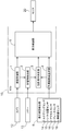
- FIG. 3 is a block diagram showing a configuration example of a vehicle periphery monitoring device according to the present invention.
- the ECU 10 is configured to include an image acquisition unit 1, an obstacle detection unit 2, a highlight display determination unit 3, a predicted track line generation unit 4 and a display control unit 5.
- the function of each functional unit of the ECU 10 is realized by cooperation of hardware such as a microprocessor and software such as a program.
- Each functional unit indicates a division as a function, and does not necessarily have to be configured physically independently.
- the traveling state detection unit 6 is a functional unit that detects a traveling state such as the speed or traveling direction of the vehicle 30, and includes the steering sensor 14, the shift position sensor 15, the accelerator sensor 16, the brake sensor 17, and the wheel speed sensor 18 described above. It is configured to be equipped.
- the configuration of the traveling state detection unit 6 is not limited to this, and may be configured of only a part of each of the above-described sensors, or may include other sensors.
- the image acquisition unit 1 is a functional unit that acquires a peripheral image of the vehicle 30 captured by the camera 12.
- the obstacle detection unit 2 is a functional unit that detects an obstacle existing around the vehicle 30 and its position based on the peripheral image acquired by the image acquisition unit 1 and the signal from the sonar 13. Note that when the obstacle detection unit 2 detects an obstacle and its position, it is not necessary to use both the peripheral image acquired by the image acquisition unit 1 and the signal from the sonar 13, and only one of them is used. It may be configured as follows.
- the predicted track line generation unit 4 is a functional unit that generates a track of the vehicle 30 (hereinafter referred to as a predicted track line) predicted from the traveling state detected by the traveling state detection unit 6.
- a predicted track line a track of the vehicle 30 predicted from the traveling state detected by the traveling state detection unit 6.
- the highlighted display determination unit 3 determines the obstacle. It is a functional unit that decides to highlight a part of the predicted travel area including the object. The predicted course line, the predicted course area, and the highlighting will be described later.
- the display control unit 5 superimposes the peripheral image of the vehicle 30 obtained by the image acquisition unit 1, the predicted course line generated by the predicted course line generation unit 4, and the highlighted display determined by the highlight display determination unit 3, It is a functional unit to be displayed on the monitor 20 in the passenger compartment.
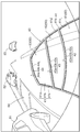
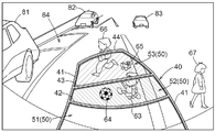
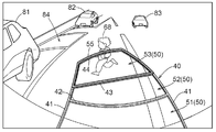
- FIG. 4 is a view showing an example of the surrounding image and the predicted course line 40 displayed on the monitor 20.
- the vehicle 30 is moved backward and parallel parking is performed in the parking space 84 between the parking vehicles 81 and 82.
- the traveling vehicle 83 is a vehicle traveling on the opposite lane.
- Such an image can be used not only for the vehicle periphery monitoring device but also for the parking assistance device.
- the predicted track line 40 includes a pair of predicted track lines 41 on the left and right that indicate the predicted track of the vehicle 30 and a distance reference line 42, 43 and 44.
- the distance reference lines 42, 43 and 44 indicate positions of 0.5 m, 1.0 m and 2.2 m from the rear end of the vehicle 30, respectively.
- the predicted track line 40 is basically drawn in yellow, but the distance reference line 42 and the predicted track line 41 on the side of the vehicle 30 from this are displayed in red in order to call the driver's attention.
- the color of the predicted course line 40, the number of the distance reference lines, the position, and the like are not limited to the above.
- the predicted course line 40 may be displayed not by a solid line but by a dotted line, a broken line or a dashed line.
- the predicted trajectory line 41 is composed of a main line portion 41a, a side surface portion 41b and a shadowed portion 41c.
- the side surface portion 41b and the shadowed portion 41c are attached to the inner side in the vehicle width direction of the main line portion 41a.
- the distance reference lines 42, 43 and 44 are respectively constituted by main line portions 42a, 43a and 44a, side portions 42b, 43b and 44b attached to the vehicle 30 side, and shadowed portions 42c, 43c and 44c.
- the predicted course line 40 is three-dimensionally displayed by attaching the side portions 41b, 42b, 43b, 44b and the shadowed portions 41c, 42c, 43c, 44c, and the driver intuitively senses the distance to the obstacle. It becomes easy to grasp.
- the predicted track line 40 changes in accordance with the traveling state detected by the traveling state detection unit 6. For example, when the steering 24 is steered, the forecasted course line 40 moves left and right on the monitor 20 in conjunction with this. If an area defined by the left and right predicted locus lines 41 and the distance reference line 44 farthest from the vehicle 30 among the predicted track lines 40 is set as a predicted track area 50 and an obstacle is present in the predicted track area 50, Highlight a partial area that includes the obstacle. In the present embodiment, it is determined whether or not to highlight each of the areas 51, 52 and 53 obtained by dividing the predicted track area 50 into three in the perspective direction by the distance reference lines 42 and 43.
- an obstacle is a concept including a person.
- the areas 51 and 53 are highlighted.
- highlighting is performed by filling the area 51 with translucent red and filling the area 53 with translucent green.
- the area 52 where the obstacles 63 and 64 are present is filled with translucent yellow
- the area 53 where the obstacles 65 and 66 are present is filled with translucent green.
- the driver refers to the predicted track line 40 so that the driver can see the vehicle and obstacles. It is easy to grasp the sense of distance intuitively. Further, since the predicted course line 40 displayed on the monitor 20 is linked to the steering of the steering 24, it is easy to determine whether or not the obstacle can be avoided by the steering of the steering 24.
- the highlighted range becomes wider compared to the case where the obstacle itself is highlighted, so that the driver The presence of an object can be easily recognized by the monitor 20.
- the color of the fill is red
- the area 51 close to the vehicle 30 is in a strong sense of imminent warning
- the area 53 far from the vehicle 30 is pale green in color
- the middle area 52 is yellow.
- the peripheral image acquired by the image acquisition unit 1 is also displayed on the monitor 20, the peripheral image can be viewed as the background of the filled area by making the filling semi-transparent. For this reason, the driver can recognize the obstacle shown in the peripheral image, and the obstacle can be easily avoided.
- the vehicle 30 has a parking assistance function, it is also possible to make the predicted course line 40 the same as the index line displayed for parking assistance.
- the driver can easily become familiar with the predicted track line 40 by using the predicted track line 40 with a plurality of functions, and grasp the perspective of the highlighted area with reference to the predicted track line 40. Becomes easy.
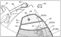
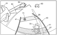
- FIG. 7 shows an example in which the outline 55 of the area 53 where the obstacle 68 is present is highlighted.
- the contour 55 is composed of distance reference lines 43 and 44 and a part of a predicted trajectory line 41 extending between them.
- the outline 55 may be filled with a specific color, displayed in a blinking manner, displayed as a thick line, or the like.
- the predicted track area 50 also includes the predicted track 40
- the area 56 points to the side closer to the obstacle 69 (in this example, the left side in FIG. 8) among the parts of the predicted trajectory line 41 that forms the outline of the area 52 including the obstacle 69.
- the area 56 may be filled with a specific color, blinked, displayed as a thick line, or the like.
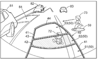
- FIG. 9 shows an example in which the predicted track line 40 does not have a distance reference line and is constituted only by the predicted track line 41.
- highlighting is performed by filling the areas 57 and 58, but the outline of the areas 57 and 58 may be highlighted.
- FIG. 11 In addition to the highlighting of the area
- the highlighting of the obstacles 73 and 74 is not limited to the filling, and other means such as a frame may be employed.
- the outline of the obstacle may be detected by image processing or the like, and the inside of the outline may not be filled.
- an obstacle may be detected by a frame, and the inside of the frame may not be filled.
- the predicted course line 40 may not be displayed partially. According to these configurations, it is easier for the driver to recognize an obstacle on the monitor 20.
- the predicted travel area 50 in the left-right direction (vehicle width direction), and the predicted travel line 40 does not have to be linked to the steering of the steering 24 and the state at a certain point It may be fixed by Further, it is possible to configure the vehicle periphery monitoring device in which the driver can intuitively grasp the sense of distance to the obstacle existing in front of the vehicle 30 by attaching the camera 12 and the sonar 13 to the front of the vehicle 30 . Furthermore, a camera 12 and a sonar 13 are attached to at least one of the left and right side portions of the vehicle 30 so that the driver can intuitively grasp the sense of distance to an obstacle present on the side of the vehicle 30 It is also possible to configure.
- the present invention can be applied to a vehicle periphery monitoring device for highlighting an obstacle on a display device provided in a vehicle cabin to alert the driver.
Landscapes
- Engineering & Computer Science (AREA)
- Mechanical Engineering (AREA)
- Physics & Mathematics (AREA)
- General Physics & Mathematics (AREA)
- Multimedia (AREA)
- Chemical & Material Sciences (AREA)
- Combustion & Propulsion (AREA)
- Transportation (AREA)
- Traffic Control Systems (AREA)
- Closed-Circuit Television Systems (AREA)
- Fittings On The Vehicle Exterior For Carrying Loads, And Devices For Holding Or Mounting Articles (AREA)
Abstract
表示装置に表示される情報が過多とならず、運転者が直感的に自車と障害物との距離感を把握可能な車両周辺監視装置を提供すべく、車両に設けられた撮影装置により撮影された車両の周辺画像を取得する画像取得部と、車両の周辺にある障害物及びその位置を検出する障害物検出部と、車両の走行状態を検出する走行状態検出部と、走行状態検出部で検出した車両の走行状態に基づいて予測進路線を生成する予測進路線生成部と、予測進路線で規定される予測進路領域に障害物が存在する場合に、予測進路領域のうち障害物を含む一部領域の強調表示を決定する強調表示決定部と、周辺画像に予測進路線及び強調表示を重畳し、重畳した画像を車両の車室内に設けられた表示装置に表示する表示制御部と、を設ける。
Description
本発明は、車室内に設けられた表示装置上で、障害物を強調表示して運転者に注意を促す車両周辺監視装置に関するものである。
従来、この種の装置として特許文献1に示すものが知られている。これは、車両周辺を撮影する撮影装置から得られる信号に基づいて、車両周辺に存在する障害物を抽出して表示装置に表示するものである。障害物の表示方法を、障害物の属性や移動方向等によって定めた危険度ごとに変えることにより、運転者が自車両と障害物との位置関係や危険の度合いを認識できるように構成されている。
特許文献2に記載の車両用周囲情報表示装置は、車両周囲物体検出手段により検出された障害物を、予め設定された模式的な絵表示に危険度情報を付加して表示するものである。この車両用周囲情報表示装置においては、上記障害物を表示する際に背景となる周囲状況を示す基本画の遠近表示レベルを設定することにより、運転者が車両周囲の状況を把握しやすいように構成されている。
特許文献1及び2に記載の装置はいずれも、障害物自体に危険度に関する情報を付加して表示する形態を採用している。したがって、対象範囲に複数の障害物が存在すると、一度に多くの情報が表示画面に表示され、運転者が迅速に周囲の状況を把握するのが困難になるおそれがある。また、自車と障害物との距離以外の要素、例えば障害物の属性や移動方向等も考慮して危険度を定めることにより、画面上に表示される障害物との距離感が把握しづらくなることが考えられる。さらに、周辺画像に障害物を重畳表示するだけでは、障害物をステアリング操作で回避可能か否かを直感的に理解することは難しい。
種々の情報を取得するために運転者が表示画面を注視しすぎると、運転に対する集中力や注意力が削がれ、事故を誘発する危険性が高くなる。このため、表示画面に過多の情報を表示するのは好ましくない。一方、車両と障害物との接触を回避するためには、運転者に自車と障害物との距離感を積極的に認識させる必要がある。本発明は以上の課題に鑑みてなされたもので、表示装置に表示される情報が過多とならず、運転者が直感的に自車と障害物との距離感を把握可能な車両周辺監視装置を提供することを目的とする。
本発明に係る車両周辺監視装置の第1特徴構成は、車両に設けられた撮影装置により撮影された前記車両の周辺画像を取得する画像取得部と、前記車両の周辺にある障害物及びその位置を検出する障害物検出部と、前記車両の走行状態を検出する走行状態検出部と、前記走行状態検出部で検出した前記車両の走行状態に基づいて予測進路線を生成する予測進路線生成部と、前記予測進路線で規定される予測進路領域に前記障害物が存在する場合に、前記予測進路領域のうち前記障害物を含む一部領域の強調表示を決定する強調表示決定部と、前記周辺画像に前記予測進路線及び前記強調表示を重畳し、重畳した画像を前記車両の車室内に設けられた表示装置に表示する表示制御部と、を備えている点にある。
第1特徴構成によれば、障害物を含むために強調表示される領域は、予測進路線によって規定される予測進路領域の一部であるから、予測進路線を参照することにより、運転者が自車と障害物との距離感を直感的に把握しやすい。また、障害物自体を個々に強調表示するのではなく、障害物が含まれる領域を強調表示するので、障害物が数多く存在する場合には、障害物ごとに強調表示がなされることによる煩わしさを回避できる。さらに、障害物が小さいために表示画面上で視認しにくい場合でも、その障害物を含む領域が強調表示されるので、運転者が障害物の存在を認識しやすくなる。
第2特徴構成は、前記強調表示を、予め前記予測進路領域を少なくとも遠近方向に複数に分割した領域ごとに行う点にある。
第2特徴構成によれば、遠近方向に分割された領域ごとに強調表示を行うので、強調表示された領域と自車との距離感の把握が容易になる。したがって、運転者が障害物までの距離を把握しやすく、障害物を回避するための操作が行いやすくなる。
第3特徴構成は、前記表示制御部は、前記予測進路線の前記撮影装置に近い側に側面部を付して表示する点にある。
第3特徴構成によれば、予測進路線が立体的に表現されるので、予測進路線を参照して、自車と障害物との距離感を把握することが容易となる。
第4特徴構成は、前記表示制御部は、前記予測進路線の前記撮影装置に近い側に影部を付して表示する点にある。
第4特徴構成によれば、予測進路線が立体的に表現されるので、予測進路線を参照して、自車と障害物との距離感を把握することが容易となる。
第5特徴構成は、前記強調表示は、前記一部領域の塗りつぶしによって行われる点にある。
第5特徴構成のごとく、強調表示が領域の塗りつぶしによって行われると、運転者が強調表示を認識しやすくなるので、障害物を見落とす危険性を低減することができる。
第6特徴構成は、前記塗りつぶしは半透明である点にある。
第6特徴構成のごとく、領域の塗りつぶしを半透明で行えば、強調表示の背景となる周辺画像も透けて見えることになる。したがって、強調表示と合わせて、実際に存在している障害物を表示装置上で認識可能となる。その結果、自車と障害物との位置関係が把握しやすく、障害物を回避するための操作を行いやすくなる。
第7特徴構成は、前記塗りつぶしの色を、前記車両と前記障害物との距離によって変更する点にある。
第7特徴構成によれば、例えば塗りつぶしの色を自車との距離が近い領域ほど警告的な意味合いを有する赤系の色、遠いほど緑あるいは青系の色にするといった形態をとれば、自車と障害物との距離を直感的に把握することが容易となる。
第8特徴構成は、前記予測進路線がステアリングの操舵に連動する点にある。
第8特徴構成によれば、予測進路線で規定される予測進路領域もステアリングの操舵に連動することになる。したがって、ステアリングを操舵したことによって障害物が予測進路領域内に含まれるようになった場合にも、当該障害物を含む領域が強調表示されることにより、運転者は新たな障害物の存在を容易に認識可能となる。また、ステアリングの操舵に連動して予測進路領域が移動するので、障害物の回避操作が容易となる。
第9特徴構成は、前記予測進路領域に相対的に近づく前記障害物を強調表示する点にある。
第9特徴構成によれば、車両の操作あるいは障害物の移動によって障害物が相対的に予測進路領域に近づいている時点で、その障害物の存在を運転者が容易に認識することができるので、障害物を回避しやすくなる。
以下、本発明に係る車両周辺監視装置の実施形態について図1~図6を用いて説明する。
図1及び図2は、本実施形態に係る車両周辺監視装置を備えた車両30の基本構成を示した図である。運転席に備えられたステアリング24は、パワーステアリングユニット33と連動し、回転操作力を前輪28fに伝えて車両30の操舵を行う。車両30の前部にはエンジン32と、このエンジン32からの動力を変速して前輪28fや後輪28rに伝える変速機構34とが配置されている。車両30の駆動方式(前輪駆動、後輪駆動、四輪駆動)に応じて、前輪28f及び後輪28rの双方もしくは何れかに動力が伝達される。
運転席の近傍には走行速度を制御するアクセルペダル26と、ブレーキ装置31を介して前輪28f及び後輪28rに制動力を作用させるブレーキペダル27とが並列配置されている。運転席の近傍のコンソールの上部位置には、モニタ20(表示装置)が備えられている。駐車支援装置やナビゲーションシステムを備えた車両30の場合は、モニタ20はこれらに利用される表示装置と兼用してもよい。
ステアリング24の操作系にはステアリングセンサ14が備えられ、ステアリング24の操舵方向と操作量とが計測される。シフトレバー25の操作系にはシフト位置センサ15が備えられ、シフト位置が判別される。また、アクセルペダル26の操作系にはアクセルセンサ16が、ブレーキペダル27の操作系にはブレーキセンサ17がそれぞれ備えられ、操作量が計測される。さらに、後輪28rの回転量を計測する車輪速センサ18が、後輪28rの近傍に設けられている。なお、これらのセンサは上記構成に限られるものではなく、実質的に同じ計測値が得られるのであれば、他の構成であっても構わない。
車両30の後部の中央部には、車両30の後方の周辺画像を撮影するカメラ12(撮影装置)が備えられている。カメラ12で撮影された周辺画像は、モニタ20で表示されるように構成されている。車両30の後部の左右両端部には、車両後方に存在する障害物を検出し、自車と障害物との距離を測定するソナー13が備えられている。また、車両30には本発明の車両周辺監視装置の中核であるECU(electronic control unit)10が配設されている。
図3は、本発明に係る車両周辺監視装置の構成例を示すブロック図である。ECU10は、画像取得部1、障害物検出部2、強調表示決定部3、予測進路線生成部4及び表示制御部5を備えて構成されている。ECU10が有する各機能部の機能は、マイクロプロセッサ等のハードウェアとプログラム等のソフトウェアとが協働することにより実現される。各機能部は、機能としての分担を示すものであり、必ずしも物理的に独立して構成される必要はない。
走行状態検出部6は、車両30の速度や走行方向等の走行状態を検出する機能部であり、上記のステアリングセンサ14、シフト位置センサ15、アクセルセンサ16、ブレーキセンサ17及び車輪速センサ18を備えて構成されている。走行状態検出部6の構成はこれに限定されるものではなく、上記各センサの一部のみから構成されてもよいし、他のセンサを備えていてもよい。
画像取得部1は、カメラ12により撮影された車両30の周辺画像を取得する機能部である。障害物検出部2は、画像取得部1で取得した周辺画像とソナー13からの信号とに基づいて、車両30の周辺に存在する障害物及びその位置を検出する機能部である。なお、障害物検出部2で障害物及びその位置を検出するに際して、必ずしも画像取得部1で取得した周辺画像とソナー13からの信号との両方を用いる必要はなく、どちらか一方のみを利用するように構成してもよい。
予測進路線生成部4は、走行状態検出部6で検出された走行状態から予測される車両30の軌跡(以降、予測進路線と称す)を生成する機能部である。強調表示決定部3は、障害物検出部2で検出された障害物の位置が、予測進路線生成部4で生成された予測進路線で規定される予測進路領域に含まれる場合に、当該障害物を含む予測進路領域の一部を強調表示することを決定する機能部である。予測進路線、予測進路領域及び強調表示については後述する。
表示制御部5は、画像取得部1で得られた車両30の周辺画像、予測進路線生成部4で生成された予測進路線及び強調表示決定部3で決定された強調表示を重畳して、車室内のモニタ20に表示させる機能部である。
図4は、モニタ20に表示される周辺画像及び予測進路線40の一例を示す図である。本実施形態では、車両30を後進させて、駐車車両81,82の間の駐車空間84に縦列駐車する状況を想定している。走行車両83は対向車線を走行する車両である。このような画像は本車両周辺監視装置に利用されるだけでなく、駐車支援装置と兼用することも可能である。
予測進路線40は、車両30の予測軌跡を示す左右一対の予測軌跡線41と距離目安線42,43,44とから構成される。本実施形態では、距離目安線42,43,44は、それぞれ車両30の後端から0.5m、1.0m、2.2mの位置を示すものとする。予測進路線40は基本的に黄色で描画されるが、距離目安線42とこれより車両30側の予測軌跡線41については、運転者に注意を喚起するため赤色で表示される。なお、予測進路線40の色や、距離目安線の本数、位置等は上記に限られるものではない。また、予測進路線40を実線ではなく、点線、破線あるいは鎖線で表示してもよい。
予測軌跡線41は、本線部41a、側面部41b及び影部41cから構成される。側面部41b及び影部41cは、本線部41aの車幅方向内側に付されている。同様に、距離目安線42,43,44もそれぞれ、本線部42a,43a,44a、車両30側に付された側面部42b,43b,44b及び影部42c,43c,44cから構成される。このように、側面部41b,42b,43b,44b及び影部41c,42c,43c,44cを付すことにより、予測進路線40が立体的に表示され、運転者が障害物との距離感を直感的に把握しやすくなる。
予測進路線40は走行状態検出部6で検出された走行状態に応じて変化する。例えば、ステアリング24を操舵すると、これに連動して予測進路線40はモニタ20上で左右に動く。予測進路線40のうち左右の予測軌跡線41と車両30から最も遠方にある距離目安線44とで規定される領域を予測進路領域50とし、予測進路領域50に障害物が存在する場合に、当該障害物を含む一部領域を強調表示する。本実施形態では、予測進路領域50を距離目安線42,43によって遠近方向に3分割した領域51,52,53ごとに強調表示するか否かを判断する。
図5及び図6は、本実施形態における強調表示の例を示したものである。なお、以下の説明において、障害物とは人も含めた概念とする。図5に示すように、領域51に障害物61が、領域53に障害物62が存在する場合には、領域51及び領域53が強調表示される。ここでは、領域51を半透明の赤色で塗りつぶし、領域53を半透明の緑色で塗りつぶすことによって、強調表示を行っている。同様に、図6に示す例は、障害物63,64が存在している領域52を半透明の黄色で塗りつぶし、障害物65,66が存在している領域53を半透明の緑色で塗りつぶすことによって、強調表示を行っている。障害物67は予測進路領域50の外に存在するので、障害物67に関連した強調表示は行われない。
強調表示される領域51,52,53は、予測進路線40によって規定される予測進路領域50の一部であるから、予測進路線40を参照することにより、運転者が自車と障害物との距離感を直感的に把握しやすい。また、モニタ20に表示される予測進路線40が、ステアリング24の操舵に連動するので、ステアリング24の操舵で障害物を回避できるか否かを判断しやすい。
図5の障害物62のように比較的小さなものが存在する場合、障害物62自体を強調表示しても、モニタ20で見落としてしまう危険性があるが、障害物62を含む領域53が強調表示されれば、見落としの危険性は大きく低減される。また、図6に示すように、多くの障害物が存在する場合に、障害物ごとに強調表示するとその数が多くなり見た目が煩わしくなるが、障害物を含む領域ごとに強調表示すれば煩わしさを回避でき、自車と障害物との距離感が把握しやすくなる。
本実施形態のように、障害物が存在する領域を塗りつぶすことによって強調表示を行えば、障害物自体を強調表示する場合と比較して、強調表示される範囲が広くなるので、運転者が障害物の存在をモニタ20で認識しやすくなる。さらに、塗りつぶしの色を上記のように、車両30との距離が近い領域51を警告的な意味合いの強い赤色、車両30から遠い領域53を警告色の薄い緑色、中間の領域52を黄色とすれば、自車と障害物との距離感を直感的に把握することが一層容易となる。さらに、モニタ20には画像取得部1で取得した周辺画像も表示されるので、塗りつぶしを半透明にすれば、塗りつぶされた領域の背景として周辺画像が見えるようになる。このため、周辺画像に映し出される障害物を、運転者が認識可能となり、障害物の回避操作が行いやすくなる。
車両30が駐車支援機能を有する場合、予測進路線40を駐車支援のために表示される指標線と同じものとすることも可能である。このように予測進路線40を複数の機能で利用することにより、運転者は予測進路線40に馴染みやすくなり、強調表示された領域の遠近感を、予測進路線40を参照して把握することが容易となる。
[別の実施形態]
以下、本発明に係る車両周辺監視装置の別の実施形態について図7~図11を用いて説明する。
以下、本発明に係る車両周辺監視装置の別の実施形態について図7~図11を用いて説明する。
図7は、障害物68が存在する領域53の輪郭55を強調表示した例である。輪郭55は、距離目安線43,44及びこれらの間に亘る予測軌跡線41の一部からなる。このときの強調表示の方法としては、輪郭55を特定の色で塗りつぶす、点滅表示する、太い線で表示する等が考えられる。このように領域53の輪郭55を強調表示することによって、背景となる周辺画像が見やすくなり、実際の障害物を認識しやすくなる。
予測進路領域50は予測進路線40をも含むと考えれば、図8のように予測進路線40の一部領域56を強調表示することも可能である。領域56は、障害物69を含む領域52の輪郭をなす予測軌跡線41の一部のうち、障害物69に近い側(本例では図8の左側)のものを指す。このような強調表示によれば、障害物69の遠近方向に関する位置を直感的に把握できるのみならず、車幅方向に関する位置についても直感的な把握が容易となる。このときの強調表示の方法としては、領域56を特定の色で塗りつぶす、点滅表示する、太い線で表示する等が考えられる。
図9は、予測進路線40が距離目安線を有さず、予測軌跡線41のみから構成される例を示す。この場合は、例えば、障害物検出部2で検出された障害物70,71の位置から遠近方向に一定距離の幅を有する帯状の領域57,58を強調表示することが考えられる。ここでは、領域57,58を塗りつぶすことによって強調表示を行っているが、領域57,58の輪郭を強調表示してもよい。
図10は、障害物72が存在する領域52の強調表示に加えて、予測進路領域50に近づいてくる障害物73を塗りつぶし59によって強調表示したものである。図11は、ステアリング24を右方向に操舵することによって、予測進路線40すなわち予測進路領域50が右に旋回し、静止している障害物74と予測進路領域50とが近づく場合に、障害物74を塗りつぶし60によって強調表示したものである。以上のように、車両30と障害物73,74との距離が相対的に近づいている段階で障害物73,74を強調表示することにより、障害物73,74の存在を運転者が容易に認識することができ、障害物73,74を回避しやすくなる。なお、障害物73,74の強調表示は塗りつぶしに限らず、枠で囲む等の他の手段を採用してもよい。
また、以上説明してきた実施形態において領域を塗りつぶす際に、障害物の輪郭を画像処理等で検出し、その輪郭の内部は塗りつぶしを行わないようにしてもよい。このほかにも、図11のように障害物を枠で検出し、当該枠の内部は塗りつぶしを行わないようにしてもよい。さらに、上記輪郭や枠の内部においては、予測進路線40を部分的に表示しないようにしてもよい。これらの構成によれば、運転者がモニタ20上で障害物を認識するのが一層容易となる。
さらに他の実施形態として、予測進路領域50を左右方向(車幅方向)に分割することも可能であるし、予測進路線40は必ずしもステアリング24の操舵に連動する必要はなく、ある時点における状態で固定してもよい。また、車両30の前部にカメラ12やソナー13を取り付け、車両30の前方に存在する障害物との距離感を運転者が直感的に把握できる車両周辺監視装置として構成することも可能である。さらに、車両30の左右の少なくとも一方の側方部にカメラ12やソナー13を取り付け、車両30の側方に存在する障害物との距離感を運転者が直感的に把握できる車両周辺監視装置として構成することも可能である。
障害物が予測進路領域50に含まれる場合に、視覚的な強調表示に加えて、車室内に設けたスピーカーから警告音を発したり、ステアリング24に振動を発生させたりすることも可能である。このとき、警告音やステアリング24の振動を段階的に変化させることによって、障害物との距離感を直感的に把握可能なように構成すると好ましい。
車室内に設けられた表示装置上で、障害物を強調表示して運転者に注意を促す車両周辺監視装置に適用できる。
1 画像取得部
2 障害物検出部
3 強調表示決定部
4 予測進路線生成部
5 表示制御部
6 走行状態検出部
12 カメラ(撮影装置)
20 モニタ(表示装置)
30 車両
40 予測進路線
50 予測進路領域
51,52,53 (遠近方向に複数に分割した)領域
2 障害物検出部
3 強調表示決定部
4 予測進路線生成部
5 表示制御部
6 走行状態検出部
12 カメラ(撮影装置)
20 モニタ(表示装置)
30 車両
40 予測進路線
50 予測進路領域
51,52,53 (遠近方向に複数に分割した)領域
Claims (9)
- 車両に設けられた撮影装置により撮影された前記車両の周辺画像を取得する画像取得部と、
前記車両の周辺にある障害物及びその位置を検出する障害物検出部と、
前記車両の走行状態を検出する走行状態検出部と、
前記走行状態検出部で検出した前記車両の走行状態に基づいて予測進路線を生成する予測進路線生成部と、
前記予測進路線で規定される予測進路領域に前記障害物が存在する場合に、前記予測進路領域のうち前記障害物を含む一部領域の強調表示を決定する強調表示決定部と、
前記周辺画像に前記予測進路線及び前記強調表示を重畳し、重畳した画像を前記車両の車室内に設けられた表示装置に表示する表示制御部と、
を備えた車両周辺監視装置。 - 前記強調表示を、予め前記予測進路領域を少なくとも遠近方向に複数に分割した領域ごとに行う請求項1に記載の車両周辺監視装置。
- 前記表示制御部は、前記予測進路線の前記撮影装置に近い側に側面部を付して表示する請求項1又は2に記載の車両周辺監視装置。
- 前記表示制御部は、前記予測進路線の前記撮影装置に近い側に影部を付して表示する請求項1~3のいずれか一項に記載の車両周辺監視装置。
- 前記強調表示は、前記一部領域の塗りつぶしによって行われる請求項1~4のいずれか一項に記載の車両周辺監視装置。
- 前記塗りつぶしは半透明である請求項5に記載の車両周辺監視装置。
- 前記塗りつぶしの色を、前記車両と前記障害物との距離によって変更する請求項5又は6に記載の車両周辺監視装置。
- 前記予測進路線がステアリングの操舵に連動する請求項1~7のいずれか一項に記載の車両周辺監視装置。
- 前記予測進路領域に相対的に近づく前記障害物を強調表示する請求項8に記載の車両周辺監視装置。
Priority Applications (3)
| Application Number | Priority Date | Filing Date | Title |
|---|---|---|---|
| US13/516,128 US8793053B2 (en) | 2010-01-19 | 2010-12-21 | Vehicle periphery monitoring device |
| EP10843976.1A EP2528330B1 (en) | 2010-01-19 | 2010-12-21 | Vehicle periphery monitoring device |
| CN201080059719.2A CN102696225B (zh) | 2010-01-19 | 2010-12-21 | 车辆周边监视装置 |
Applications Claiming Priority (2)
| Application Number | Priority Date | Filing Date | Title |
|---|---|---|---|
| JP2010009246A JP5071743B2 (ja) | 2010-01-19 | 2010-01-19 | 車両周辺監視装置 |
| JP2010-009246 | 2010-01-19 |
Publications (1)
| Publication Number | Publication Date |
|---|---|
| WO2011089812A1 true WO2011089812A1 (ja) | 2011-07-28 |
Family
ID=44306628
Family Applications (1)
| Application Number | Title | Priority Date | Filing Date |
|---|---|---|---|
| PCT/JP2010/072973 WO2011089812A1 (ja) | 2010-01-19 | 2010-12-21 | 車両周辺監視装置 |
Country Status (5)
| Country | Link |
|---|---|
| US (1) | US8793053B2 (ja) |
| EP (1) | EP2528330B1 (ja) |
| JP (1) | JP5071743B2 (ja) |
| CN (1) | CN102696225B (ja) |
| WO (1) | WO2011089812A1 (ja) |
Cited By (5)
| Publication number | Priority date | Publication date | Assignee | Title |
|---|---|---|---|---|
| FR2979299A1 (fr) * | 2011-08-31 | 2013-03-01 | Peugeot Citroen Automobiles Sa | Dispositif de traitement pour estimer une trajectoire future d'un vehicule, associee a une couleur fonction d'un niveau de risque de collision estime, pour un systeme d'aide a la conduite |
| FR2979311A1 (fr) * | 2011-08-31 | 2013-03-01 | Peugeot Citroen Automobiles Sa | Dispositif de traitement pour associer a un element graphique une couleur en fonction d'un niveau de risque de collision d'un obstacle avec une trajectoire future d'un vehicule, pour un systeme d'aide a la conduite |
| FR2979300A1 (fr) * | 2011-08-31 | 2013-03-01 | Peugeot Citroen Automobiles Sa | Dispositif pour estimer une trajectoire future d'un vehicule et associer a des parties qu'elle comprend des aspects differents selon leurs positions par rapport a un obstacle, pour un systeme d'aide a la conduite |
| JP5909289B2 (ja) * | 2012-12-12 | 2016-04-26 | 本田技研工業株式会社 | 駐車スペース検出装置 |
| JP2017138660A (ja) * | 2016-02-01 | 2017-08-10 | トヨタ自動車株式会社 | 物体検出方法、物体検出装置、およびプログラム |
Families Citing this family (64)
| Publication number | Priority date | Publication date | Assignee | Title |
|---|---|---|---|---|
| JP2011234031A (ja) * | 2010-04-26 | 2011-11-17 | Kyocera Corp | 車載用撮像装置 |
| US20120016555A1 (en) * | 2010-07-18 | 2012-01-19 | Maher Ghneim | Method and system for parking assist |
| US8665116B2 (en) | 2010-07-18 | 2014-03-04 | Ford Global Technologies | Parking assist overlay with variable brightness intensity |
| JP5459154B2 (ja) * | 2010-09-15 | 2014-04-02 | トヨタ自動車株式会社 | 車両用周囲画像表示装置及び方法 |
| JP5674071B2 (ja) * | 2011-11-01 | 2015-02-25 | アイシン精機株式会社 | 障害物警報装置 |
| US9396401B2 (en) | 2011-11-01 | 2016-07-19 | Aisin Seiki Kabushiki Kaisha | Obstacle alarm device |
| WO2013065122A1 (ja) * | 2011-11-01 | 2013-05-10 | アイシン精機株式会社 | 障害物警報装置 |
| JP5692403B2 (ja) * | 2011-11-01 | 2015-04-01 | アイシン精機株式会社 | 障害物警報装置 |
| JP5821622B2 (ja) * | 2011-12-26 | 2015-11-24 | アイシン精機株式会社 | 障害物警報装置 |
| JP5747847B2 (ja) * | 2012-03-14 | 2015-07-15 | トヨタ自動車株式会社 | 車両周辺監視装置 |
| CN102848980A (zh) * | 2012-10-11 | 2013-01-02 | 南京艾酷派物联网有限公司 | 环境泊车安全辅助装置 |
| US8885756B1 (en) * | 2012-10-15 | 2014-11-11 | Maritime Telecommunications Network Inc. | Multi-antenna/multilink diversity management for mobile communication platform |
| GB2510167B (en) | 2013-01-28 | 2017-04-19 | Jaguar Land Rover Ltd | Vehicle path prediction and obstacle indication system and method |
| JP6123133B2 (ja) * | 2013-03-04 | 2017-05-10 | パナソニックIpマネジメント株式会社 | 車両用障害物検知装置および、車両用障害物検知システム |
| JP2014204361A (ja) * | 2013-04-08 | 2014-10-27 | 株式会社ビートソニック | 車載モニタリングシステムにおける車載カメラ用アダプター |
| JP2015008453A (ja) * | 2013-05-29 | 2015-01-15 | 京セラ株式会社 | カメラ装置および警告方法 |
| BR112016006666B1 (pt) * | 2013-09-27 | 2023-04-04 | Nissan Motor Co., Ltd | Sistema de apresentação de informações |
| JP6134668B2 (ja) * | 2014-02-18 | 2017-05-24 | 日立建機株式会社 | 作業車両の障害物検知装置 |
| DE102014003784A1 (de) * | 2014-03-15 | 2015-09-17 | Audi Ag | Verfahren zur Fahrerinformation in einem Kraftfahrzeug |
| JP6252316B2 (ja) * | 2014-03-31 | 2017-12-27 | 株式会社デンソー | 車両用表示制御装置 |
| CA2863656C (en) | 2014-04-25 | 2017-04-25 | Takeshi Kurihara | Surroundings monitoring system, work vehicle, and surroundings monitoring method |
| JP6307383B2 (ja) | 2014-08-07 | 2018-04-04 | 日立オートモティブシステムズ株式会社 | 行動計画装置 |
| WO2016084149A1 (ja) * | 2014-11-26 | 2016-06-02 | 三菱電機株式会社 | 運転支援装置および運転支援方法 |
| DE102015201317A1 (de) * | 2015-01-27 | 2016-07-28 | Bayerische Motoren Werke Aktiengesellschaft | Vermessen einer Abmessung auf einer Oberfläche |
| US20180025634A1 (en) * | 2015-03-12 | 2018-01-25 | Mitsubishi Electric Corporation | Vehicle group management apparatus, vehicle group management method, computer readable medium, and vehicle group display apparatus |
| DE102015216881A1 (de) * | 2015-09-03 | 2017-03-09 | Robert Bosch Gmbh | Verfahren und Vorrichtung zum fahrerlosen Führen eines Kraftfahrzeugs innerhalb eines Parkplatzes |
| US9873428B2 (en) * | 2015-10-27 | 2018-01-23 | Ford Global Technologies, Llc | Collision avoidance using auditory data |
| JP6601679B2 (ja) * | 2016-03-01 | 2019-11-06 | パナソニックIpマネジメント株式会社 | 判定装置、判定方法、および判定プログラム |
| US10656265B2 (en) * | 2016-03-14 | 2020-05-19 | Hitachi Construction Machinery Co., Ltd. | Mining work machine |
| JP6366881B2 (ja) * | 2016-04-15 | 2018-08-01 | 三菱電機株式会社 | 駐車支援装置 |
| JP6595401B2 (ja) * | 2016-04-26 | 2019-10-23 | 株式会社Soken | 表示制御装置 |
| JP6390035B2 (ja) * | 2016-05-23 | 2018-09-19 | 本田技研工業株式会社 | 車両制御システム、車両制御方法、および車両制御プログラム |
| CN107640147B (zh) * | 2016-07-18 | 2020-12-04 | 奥迪股份公司 | 泊车辅助方法和系统 |
| JP6776702B2 (ja) * | 2016-07-29 | 2020-10-28 | アイシン精機株式会社 | 周辺監視装置 |
| US11528413B2 (en) * | 2016-08-22 | 2022-12-13 | Sony Corporation | Image processing apparatus and image processing method to generate and display an image based on a vehicle movement |
| JP6776058B2 (ja) * | 2016-08-26 | 2020-10-28 | シャープ株式会社 | 自律走行車両制御装置、自律走行車両制御システム及び自律走行車両制御方法 |
| FR3055870B1 (fr) * | 2016-09-15 | 2019-09-27 | Renault S.A.S. | Methode d'aide a la conduite, procede d'implementation d'une telle methode et dispositif d'aide a la conduite |
| JPWO2018096644A1 (ja) * | 2016-11-25 | 2019-10-17 | 本田技研工業株式会社 | 車両用表示制御装置、車両用表示制御方法、および車両用表示制御プログラム |
| EP4155128A1 (en) | 2016-12-09 | 2023-03-29 | Kyocera Corporation | Imaging apparatus, image processing apparatus, display system, and vehicle |
| JP6974564B2 (ja) * | 2016-12-09 | 2021-12-01 | 京セラ株式会社 | 表示制御装置 |
| JP6565893B2 (ja) * | 2016-12-26 | 2019-08-28 | トヨタ自動車株式会社 | 運転支援装置 |
| JP2018110328A (ja) | 2017-01-04 | 2018-07-12 | 株式会社デンソーテン | 画像処理装置および画像処理方法 |
| FR3061780B1 (fr) * | 2017-01-12 | 2022-08-19 | Valeo Schalter & Sensoren Gmbh | Procede de pilotage d'un afficheur de vehicule automobile, et afficheur correspondant |
| US10885788B2 (en) * | 2017-04-24 | 2021-01-05 | Mitsubishi Electric Corporation | Notification control apparatus and method for controlling notification |
| JP6760211B2 (ja) * | 2017-06-16 | 2020-09-23 | 株式会社Jvcケンウッド | 表示制御装置、表示制御システム、表示制御方法及び表示制御プログラム |
| WO2018230021A1 (ja) | 2017-06-16 | 2018-12-20 | 株式会社Jvcケンウッド | 表示制御装置、表示制御システム、表示制御方法及び表示制御プログラム |
| JP6760210B2 (ja) * | 2017-06-16 | 2020-09-23 | 株式会社Jvcケンウッド | 表示制御装置、表示制御システム、表示制御方法及び表示制御プログラム |
| CN110914882B (zh) * | 2017-07-05 | 2022-02-08 | 三菱电机株式会社 | 显示系统和显示方法 |
| US10960820B2 (en) | 2017-08-03 | 2021-03-30 | Mitsubishi Electric Corporation | Vehicle periphery image display device and vehicle periphery image display method |
| JP6555599B2 (ja) * | 2017-08-04 | 2019-08-07 | 本田技研工業株式会社 | 表示システム、表示方法、およびプログラム |
| DE102017215519A1 (de) | 2017-09-05 | 2019-03-07 | Robert Bosch Gmbh | Verfahren und Vorrichtung zur Kollisionserkennung für ein Fahrzeug |
| CN110843910A (zh) * | 2018-08-21 | 2020-02-28 | 上海博泰悦臻网络技术服务有限公司 | 车辆拐弯控制装置及方法 |
| JP7088807B2 (ja) * | 2018-10-29 | 2022-06-21 | 京セラ株式会社 | 画像処理装置、カメラ、移動体および画像処理方法 |
| KR20200056497A (ko) * | 2018-11-09 | 2020-05-25 | 현대자동차주식회사 | 자율 발렛 주차를 지원하는 시스템 및 방법, 그리고 이를 위한 인프라 및 차량 |
| CN109774618A (zh) * | 2019-01-23 | 2019-05-21 | 钟辉 | 一种无盲区的车载影像系统及其显示方法 |
| CN109901575A (zh) * | 2019-02-20 | 2019-06-18 | 百度在线网络技术(北京)有限公司 | 车辆路线规划调试方法、装置、设备及计算机可读介质 |
| JP2020154369A (ja) * | 2019-03-18 | 2020-09-24 | 株式会社Jvcケンウッド | 障害物情報管理装置、障害物情報管理方法、及び障害物情報管理プログラム |
| JP7209189B2 (ja) * | 2019-03-25 | 2023-01-20 | パナソニックIpマネジメント株式会社 | 画像生成装置、カメラ、表示システム、車両及び画像生成方法 |
| JP7259698B2 (ja) * | 2019-10-17 | 2023-04-18 | トヨタ自動車株式会社 | 自動駐車システム |
| JP7284458B2 (ja) * | 2019-10-17 | 2023-05-31 | 三菱自動車工業株式会社 | 駐車支援装置 |
| JP7007438B2 (ja) * | 2020-09-09 | 2022-01-24 | 京セラ株式会社 | 撮像装置、画像処理装置、表示装置、表示システム、および車両 |
| DE102021126950A1 (de) | 2021-10-18 | 2023-04-20 | Bayerische Motoren Werke Aktiengesellschaft | Steuerverfahren und steuervorrichtung für eine anzeigevorrichtung in einem kraftfahrzeuginnenraum |
| US20230256985A1 (en) * | 2022-02-14 | 2023-08-17 | Continental Advanced Lidar Solutions Us, Llc | Method and system for avoiding vehicle undercarriage collisions |
| WO2024058922A1 (en) * | 2022-09-16 | 2024-03-21 | Indian Motorcycle International, LLC | Vehicle proximity display on user interface |
Citations (8)
| Publication number | Priority date | Publication date | Assignee | Title |
|---|---|---|---|---|
| JPH07223488A (ja) | 1994-02-14 | 1995-08-22 | Mitsubishi Motors Corp | 車両用周囲情報表示装置 |
| JPH10117340A (ja) * | 1996-10-11 | 1998-05-06 | Yazaki Corp | 車両周辺監視装置、この装置に用いられる警報表示方法、及びこの表示方法を記憶した媒体 |
| JP2000177513A (ja) * | 1998-12-16 | 2000-06-27 | Toyota Autom Loom Works Ltd | 車両における後退支援装置及び車両 |
| JP2002029346A (ja) * | 2000-07-14 | 2002-01-29 | Hiroyuki Yokozawa | 自動車の運転支援システム及び運転支援プログラムを記録した記録媒体 |
| JP2004203068A (ja) * | 2002-12-24 | 2004-07-22 | Aisin Seiki Co Ltd | 移動体周辺監視装置 |
| JP2009040108A (ja) | 2007-08-06 | 2009-02-26 | Denso Corp | 画像表示制御装置及び画像表示制御システム |
| JP2009265803A (ja) * | 2008-04-23 | 2009-11-12 | Panasonic Corp | 車両視界支援装置 |
| JP2009292457A (ja) * | 2008-05-08 | 2009-12-17 | Aisin Seiki Co Ltd | 車両周辺表示装置 |
Family Cites Families (3)
| Publication number | Priority date | Publication date | Assignee | Title |
|---|---|---|---|---|
| US6411867B1 (en) * | 1999-10-27 | 2002-06-25 | Fujitsu Ten Limited | Vehicle driving support system, and steering angle detection device |
| JP3645196B2 (ja) * | 2001-02-09 | 2005-05-11 | 松下電器産業株式会社 | 画像合成装置 |
| JP4404103B2 (ja) * | 2007-03-22 | 2010-01-27 | 株式会社デンソー | 車両外部撮影表示システムおよび画像表示制御装置 |
-
2010
- 2010-01-19 JP JP2010009246A patent/JP5071743B2/ja active Active
- 2010-12-21 US US13/516,128 patent/US8793053B2/en active Active
- 2010-12-21 CN CN201080059719.2A patent/CN102696225B/zh active Active
- 2010-12-21 WO PCT/JP2010/072973 patent/WO2011089812A1/ja active Application Filing
- 2010-12-21 EP EP10843976.1A patent/EP2528330B1/en active Active
Patent Citations (8)
| Publication number | Priority date | Publication date | Assignee | Title |
|---|---|---|---|---|
| JPH07223488A (ja) | 1994-02-14 | 1995-08-22 | Mitsubishi Motors Corp | 車両用周囲情報表示装置 |
| JPH10117340A (ja) * | 1996-10-11 | 1998-05-06 | Yazaki Corp | 車両周辺監視装置、この装置に用いられる警報表示方法、及びこの表示方法を記憶した媒体 |
| JP2000177513A (ja) * | 1998-12-16 | 2000-06-27 | Toyota Autom Loom Works Ltd | 車両における後退支援装置及び車両 |
| JP2002029346A (ja) * | 2000-07-14 | 2002-01-29 | Hiroyuki Yokozawa | 自動車の運転支援システム及び運転支援プログラムを記録した記録媒体 |
| JP2004203068A (ja) * | 2002-12-24 | 2004-07-22 | Aisin Seiki Co Ltd | 移動体周辺監視装置 |
| JP2009040108A (ja) | 2007-08-06 | 2009-02-26 | Denso Corp | 画像表示制御装置及び画像表示制御システム |
| JP2009265803A (ja) * | 2008-04-23 | 2009-11-12 | Panasonic Corp | 車両視界支援装置 |
| JP2009292457A (ja) * | 2008-05-08 | 2009-12-17 | Aisin Seiki Co Ltd | 車両周辺表示装置 |
Non-Patent Citations (1)
| Title |
|---|
| See also references of EP2528330A4 |
Cited By (8)
| Publication number | Priority date | Publication date | Assignee | Title |
|---|---|---|---|---|
| FR2979299A1 (fr) * | 2011-08-31 | 2013-03-01 | Peugeot Citroen Automobiles Sa | Dispositif de traitement pour estimer une trajectoire future d'un vehicule, associee a une couleur fonction d'un niveau de risque de collision estime, pour un systeme d'aide a la conduite |
| FR2979311A1 (fr) * | 2011-08-31 | 2013-03-01 | Peugeot Citroen Automobiles Sa | Dispositif de traitement pour associer a un element graphique une couleur en fonction d'un niveau de risque de collision d'un obstacle avec une trajectoire future d'un vehicule, pour un systeme d'aide a la conduite |
| FR2979300A1 (fr) * | 2011-08-31 | 2013-03-01 | Peugeot Citroen Automobiles Sa | Dispositif pour estimer une trajectoire future d'un vehicule et associer a des parties qu'elle comprend des aspects differents selon leurs positions par rapport a un obstacle, pour un systeme d'aide a la conduite |
| WO2013030480A1 (fr) * | 2011-08-31 | 2013-03-07 | Peugeot Citroen Automobiles Sa | Dispositif pour estimer une trajectoire future d'un véhicule et associer à des parties qu'elle comprend des aspects différents selon leurs positions par rapport à un obstacle, pour un système d'aide à la conduite |
| CN103764485A (zh) * | 2011-08-31 | 2014-04-30 | 标致·雪铁龙汽车公司 | 用于驾驶辅助系统的用于估算运输工具的未来路线并且与部件相关联的装置,所述未来路线包括根据相对于障碍物位置的不同外观 |
| CN103764485B (zh) * | 2011-08-31 | 2016-06-22 | 标致·雪铁龙汽车公司 | 用于驾驶辅助系统的装置 |
| JP5909289B2 (ja) * | 2012-12-12 | 2016-04-26 | 本田技研工業株式会社 | 駐車スペース検出装置 |
| JP2017138660A (ja) * | 2016-02-01 | 2017-08-10 | トヨタ自動車株式会社 | 物体検出方法、物体検出装置、およびプログラム |
Also Published As
| Publication number | Publication date |
|---|---|
| JP2011151479A (ja) | 2011-08-04 |
| US8793053B2 (en) | 2014-07-29 |
| CN102696225B (zh) | 2014-10-08 |
| US20120296523A1 (en) | 2012-11-22 |
| CN102696225A (zh) | 2012-09-26 |
| EP2528330A4 (en) | 2016-11-30 |
| EP2528330B1 (en) | 2020-03-25 |
| JP5071743B2 (ja) | 2012-11-14 |
| EP2528330A1 (en) | 2012-11-28 |
Similar Documents
| Publication | Publication Date | Title |
|---|---|---|
| WO2011089812A1 (ja) | 車両周辺監視装置 | |
| JP2011151479A5 (ja) | ||
| JP6806156B2 (ja) | 周辺監視装置 | |
| JP5636609B2 (ja) | 車両周辺表示装置 | |
| JP6387369B2 (ja) | 走行制御装置 | |
| US8384561B2 (en) | Parking assist device | |
| JP6897340B2 (ja) | 周辺監視装置 | |
| JP5454934B2 (ja) | 運転支援装置 | |
| EP2253529B1 (en) | Driving assist apparatus | |
| EP2910423B1 (en) | Surroundings monitoring apparatus and program thereof | |
| JP4623396B2 (ja) | 車両周辺表示装置 | |
| JP5991112B2 (ja) | 駐車支援装置、制御方法、およびプログラム | |
| JP2017094922A (ja) | 周辺監視装置 | |
| JP2012147285A (ja) | バックモニタ装置 | |
| JP2018207289A (ja) | 周辺表示装置 | |
| JP2014069721A (ja) | 周辺監視装置、制御方法、及びプログラム | |
| JP6953915B2 (ja) | 周辺監視装置 | |
| JP7130923B2 (ja) | 表示制御装置 | |
| JP6606956B2 (ja) | 周辺監視装置 | |
| JP2013135316A (ja) | 障害物警報装置 |
Legal Events
| Date | Code | Title | Description |
|---|---|---|---|
| 121 | Ep: the epo has been informed by wipo that ep was designated in this application |
Ref document number: 10843976 Country of ref document: EP Kind code of ref document: A1 |
|
| WWE | Wipo information: entry into national phase |
Ref document number: 2010843976 Country of ref document: EP |
|
| WWE | Wipo information: entry into national phase |
Ref document number: 13516128 Country of ref document: US |
|
| NENP | Non-entry into the national phase |
Ref country code: DE |