WO2011089720A1 - 歩行者保護エアバッグ装置 - Google Patents
歩行者保護エアバッグ装置 Download PDFInfo
- Publication number
- WO2011089720A1 WO2011089720A1 PCT/JP2010/050847 JP2010050847W WO2011089720A1 WO 2011089720 A1 WO2011089720 A1 WO 2011089720A1 JP 2010050847 W JP2010050847 W JP 2010050847W WO 2011089720 A1 WO2011089720 A1 WO 2011089720A1
- Authority
- WO
- WIPO (PCT)
- Prior art keywords
- airbag
- door mirror
- door
- main body
- pedestrian protection
- Prior art date
- Legal status (The legal status is an assumption and is not a legal conclusion. Google has not performed a legal analysis and makes no representation as to the accuracy of the status listed.)
- Ceased
Links
Images







Classifications
-
- B—PERFORMING OPERATIONS; TRANSPORTING
- B60—VEHICLES IN GENERAL
- B60R—VEHICLES, VEHICLE FITTINGS, OR VEHICLE PARTS, NOT OTHERWISE PROVIDED FOR
- B60R21/00—Arrangements or fittings on vehicles for protecting or preventing injuries to occupants or pedestrians in case of accidents or other traffic risks
- B60R21/34—Protecting non-occupants of a vehicle, e.g. pedestrians
- B60R21/36—Protecting non-occupants of a vehicle, e.g. pedestrians using airbags
Definitions
- the present invention relates to a pedestrian protection airbag device in which an airbag is inflated and deployed outside a vehicle at the time of collision with a pedestrian or when a collision is predicted.
- Patent Document 1 Japanese Patent Laid-Open No. 2009-006957 discloses a technique for inflating and deploying an airbag in front of a front pillar when a collision with a pedestrian occurs.
- the airbag module is stored in the front edge portion of the door frame or the door mirror base portion.
- the inflator is activated and gas is supplied into the folded airbag.
- the airbag is inflated and deployed on the front surface of the front pillar.
- a small support inflating portion is provided on the outer side of the inflating body portion in the vehicle width direction, and a part of the supporting inflating portion is in contact with and supported on the inner side surface of the door mirror body in the vehicle width direction when the airbag is inflated and deployed. It is supposed to let you. This prevents the airbag after deployment from shifting outward in the vehicle width direction with respect to the front surface of the front pillar.
- the airbag since the airbag has a structure that inflates and deploys from the outer side in the vehicle width direction of the front pillar to the front surface of the front pillar, the airbag is inherently easily displaced (easily escaped) to the outer side in the vehicle width direction. For this reason, the airbag can be mounted on the vehicle by merely bringing a part of the support inflating portion into contact with the inner side surface in the vehicle width direction of the door mirror main body that protrudes outward in the vehicle width direction from the side door as in the above prior art. Insufficient to suppress shifting outward in the width direction. Therefore, the prior art has room for improvement in this respect.
- the present invention has been made in consideration of the above facts, and an object of the present invention is to provide a pedestrian protection airbag device that can suppress the airbag from shifting (escape) outward in the vehicle width direction when a pedestrian is received.
- a pedestrian protection airbag device is provided in a side door or a door mirror device, and is operated to generate a gas, and is stored in a folded state and supplied with gas from the inflator.
- An assembly of a plurality of cells is included, and a connecting portion for connecting cells adjacent to each other is positioned closer to the front pillar than the center of the cell.
- the pedestrian protection airbag device is the first aspect, wherein the airbag includes an inner base fabric portion disposed on the front pillar side and an outer base disposed on the opposite side of the front pillar.
- the circumference of the portion constituted by the inner base fabric portion is larger than the circumference of the portion constituted by the outer base fabric portion. It is characterized by being set short.
- the cell in the first or second aspect, is formed in an elongated shape whose longitudinal direction is a direction along the front pillar, and further, Adjacent cells are in contact with each other along the longitudinal direction of the cells.
- the door mirror main body when in use, is projected from the upper front end side of the side door to the outside in the vehicle width direction and stored.
- the door mirror body When applied to vehicles equipped with a door mirror device that is folded so that the door mirror body rotates about the axis and follows the longitudinal direction of the front pillar, and the door mirror body is used at the time of a collision or when a collision is predicted. It is characterized by comprising a door mirror posture changing means for forcibly moving the lens to the storage position.
- a pedestrian protection airbag apparatus is the fourth aspect.
- the door mirror device is provided in the door mirror main body and driven to drive the airbag.
- the door mirror main body is configured to include a drive motor that rotates about the axis, and the door mirror attitude changing means drives the drive motor at the time of the collision prediction to move the door mirror main body from the use position to the storage position. It is a control device that is forcibly moved.
- the door mirror attitude changing means includes a cylinder fixed to a non-movable part of the side door or the door mirror device, the inflator, and the cylinder.
- a communication member that supplies a part of the gas generated in the inflator into the cylinder, and is accommodated in the inflator so as to be axially movable, and the chamber in the cylinder is connected to the side to which the communication member is connected.
- a piston that is partitioned into a first chamber and a second chamber that is not connected to the communication member, and one end of the piston is fixed to the piston, and the door mirror main body is forcibly moved from the use position to the storage position.
- a push-up part having the other end arranged at a position where the pressing force to be applied can be applied to the door mirror main body part.
- the pedestrian protection airbag apparatus is the pedestrian protection airbag apparatus according to the fourth aspect, wherein the airbag is inflated and deployed so as to cover at least the lower part of the front surface of the front pillar, and the airbag. And an airbag branch portion that is branched from the main body portion and inflated and deployed on the lower side of the door mirror main body portion, and the door mirror attitude changing means is configured as the airbag branch portion. It is characterized by that.
- the pedestrian protection airbag device is the pedestrian protection airbag device according to any one of the first to third aspects, wherein the airbag is removed from a storage position in the side door or door mirror device at the time of collision or at the time of collision prediction.
- a moving means for moving the front pillar to an outer position in the vehicle width direction is provided.
- the pedestrian protection airbag apparatus is the eighth aspect, wherein the moving means has one end connected to the inflator and the other end communicated with a lower portion of the airbag. It is characterized by including a tube-like push-up part that extends toward the front pillar when the gas from the pipe is supplied.
- a pedestrian protection airbag apparatus is the eighth aspect, wherein the moving means includes a drive motor that is activated at the time of the collision prediction, and an airbag module that includes at least the airbag.
- the moving means includes a drive motor that is activated at the time of the collision prediction, and an airbag module that includes at least the airbag.
- a lifting mechanism that raises the front pillar to a position outside the vehicle width direction of the front pillar, and a driving force transmission mechanism that transmits the driving force of the drive motor to the lifting mechanism. Yes.
- the airbag since the gas is not generated before the inflator is activated, the airbag is stored in a folded state. When the inflator is activated from this state, gas is generated from the inflator. The generated gas is supplied into the folded airbag. Thereby, the airbag is inflated outside the side door or the door mirror device. As a result, at least the lower part of the front surface of the front pillar is covered with the airbag. Thereby, a pedestrian is protected.
- the airbag is configured to include an aggregate of a plurality of cells that are deployed along the front pillar, and the connection portion that connects the cells adjacent to each other is more than the center of the cell. Located on the front pillar side. For this reason, when gas is supplied to a plurality of cells, the cells adjacent to each other are pressed against each other, so that the plurality of cells fall to the front pillar side.
- the cell located downstream in the gas supply direction is centered on the connection part with the cell located upstream in the gas supply direction, and the cell is located from the connection part.
- a rotational moment is applied with the distance to the contact area where the cells are pressed against each other as the arm length. This rotational moment is a force that presses a cell located downstream in the gas supply direction toward the front pillar. Then, this rotational moment is sequentially and sequentially repeated with two adjacent cells as one unit.
- the plurality of cells fall to the front pillar side.
- the plurality of cells strongly pressed against the front surface of the front pillar easily move outward in the vehicle width direction. do not do.
- the airbag is configured by overlapping and sewing the inner base fabric portion disposed on the front pillar side and the outer base fabric portion disposed on the opposite side of the front pillar. Yes.
- the circumference of the portion constituted by the inner base fabric portion in the cell is set shorter than the circumference of the portion constituted by the outer base fabric portion, gas is supplied into the cell. Then, when the cell expands, the cell falls down toward the shorter circumference. In other words, it is only necessary to determine the sewing position (that is, the position of the connecting portion) so that the circumference of the portion constituted by the inner base fabric portion is shorter than the circumference of the portion constituted by the outer base fabric portion. . Therefore, the configuration is established without any increase in the number of parts.
- the cells are formed in an elongated shape whose longitudinal direction is the direction along the front pillar, and the cells adjacent to each other are in contact with each other along the longitudinal direction of the cells. For this reason, the cell located on the upstream side in the gas supply direction can support the cell located on the downstream side in the gas supply direction adjacent thereto with a large contact area. Therefore, the inflated airbag can be firmly supported.
- the door mirror main body portion when used, extends outward from the upper front end side of the side door in the vehicle width direction, and when stored, the door mirror main body portion rotates about the axis so as to follow the longitudinal direction of the front pillar.
- a vehicle including a door mirror device to be folded is an application target.
- the door mirror main body when the vehicle is running, the door mirror main body is held at the use position in a case other than a collision or a collision prediction. For this reason, the door mirror main-body part is projected from the upper front end side of the side door to the vehicle width direction outer side. From this state, when a collision occurs or when a collision is predicted, an inflator of an airbag module provided in the side door or the door mirror device is activated to generate gas. This gas is supplied into the airbag stored in a folded state. For this reason, the airbag is inflated to the outside of the side or the door mirror device, and at least the lower part of the front surface of the front pillar is covered. As a result, pedestrians are protected.
- the door mirror attitude changing means is activated.
- the door mirror main body is forcibly moved from the use position to the storage position.
- the airbag is supported from the outside in the vehicle width direction by the door mirror main body.
- the door mirror main body exists as a “wall” on the outer side of the airbag in the vehicle width direction.
- the airbag is held on the front surface of the front pillar in a stable state.
- the mirror main body serves as a wall to prevent the airbag from moving outward in the vehicle width direction even if the airbag tends to shift outward in the vehicle width direction.
- the door mirror device is configured as a so-called electric retractable door mirror device including a drive motor.
- the door mirror attitude changing means is configured as a control device that controls the drive of the drive motor. When a collision is predicted, the drive motor is automatically driven by the control device, and the door mirror main body is forcibly moved from the use position to the storage position.
- the door mirror main body is forcibly moved from the use position to the storage position by the control device at the time of collision prediction, it is necessary to add a new member or the like as the door mirror attitude changing means. There is no need to change the design of the airbag module. For this reason, the number of parts does not increase and it is not necessary to expand the vehicle mounting space.
- the inflator when the inflator is activated, a part of the gas is supplied to the first chamber of the cylinder via the communication member. For this reason, the pressure in the first chamber is increased, and the piston that divides the first chamber and the second chamber moves in the cylinder in the direction in which the second chamber is compressed. Since one end of the push-up portion is fixed to the piston, when the piston moves in the cylinder in the axial direction, the push-up member also moves in the same direction.
- the push-up member Since the other end of the push-up member is disposed at a predetermined position in the door mirror main body (that is, a position at which a pressing force for moving the door mirror main body from the use position to the storage position can be applied to the door mirror main body), the push-up member is When it moves, the door mirror body is pressed by the other end. As a result, the door mirror main body is forcibly moved from the use position to the storage position.
- the door mirror main body can be forcibly moved from the use position to the storage position in a state where the door mirror main body is completely or almost completely mechanically connected. High reliability.
- the airbag when the inflator is activated, gas is supplied into the airbag.
- the airbag is configured to include an airbag main body portion for protecting a pedestrian and an airbag branch portion functioning as a door mirror posture changing means. For this reason, when the airbag is inflated and deployed, both the airbag body portion and the airbag branch portion are inflated and deployed. That is, the airbag branch portion is inflated and deployed below the door mirror main body portion, and the airbag main body portion is inflated and deployed so as to cover at least the lower part of the front surface of the front pillar.
- a door mirror main-body part is forcedly pushed up from a use position to the storage position side by an airbag branch part. By this.
- the door mirror main body is held in the retracted position and supports the airbag main body from the outside in the vehicle width direction.
- the shape of the airbag is changed, and the door mirror main body is forcibly moved from the use position to the storage position only by making the output of the inflator commensurate with the capacity of the airbag. Can be made.
- the airbag when a collision or a collision prediction occurs, the airbag is moved from the retracted position in the side door or the door mirror device to the outer position in the vehicle width direction of the front pillar by the moving means. For this reason, the airbag is inflated and deployed from a position closer to the front surface of the front pillar. Therefore, the time until the airbag is inflated and deployed on the front surface of the front pillar is shorter than the configuration in which the airbag is inflated and deployed from within the side door or the door mirror device.
- the moving means is configured to include a tube-like push-up portion having one end connected to the inflator and the other end communicated with the lower portion of the airbag.
- the push-up portion When gas is generated from the inflator at the time of prediction, the push-up portion first expands and extends toward the front pillar. And if a tube extends to the vehicle width direction outer side position of the front surface of a front pillar, an airbag will be inflate-deployed. Thereby, at least the lower part of the front surface of the front pillar is covered with the airbag.
- the moving means can be established by the tube-shaped push-up portion, the structure can be simplified and the parts can be simplified as compared with the case where the moving means is established using another mechanical mechanism. There is no need to secure installation space.
- the drive motor of the moving means when the collision is predicted, the drive motor of the moving means is operated.
- the drive motor When the drive motor operates, the drive force is transmitted to the lifting mechanism via the drive force transmission mechanism.
- the lift mechanism raises the airbag module including at least the airbag from the retracted position to the outer position in the vehicle width direction of the front pillar.
- the airbag is inflated and deployed from that position to cover at least the lower part of the front surface of the front pillar.
- the moving means is configured to include the drive motor, the driving force transmission mechanism, and the lifting mechanism, the number of parts increases, but the airbag module is mechanically operated to move the front pillar in the vehicle width direction outside. It can be moved to a position. For this reason, the position at the start of deployment of the airbag is difficult to shift.
- the pedestrian protection airbag device has an excellent effect that the airbag can be prevented from shifting (escape) outward in the vehicle width direction when the pedestrian is received.
- the pedestrian protection airbag device has an excellent effect that the above-described effect can be obtained at low cost.
- the pedestrian protection airbag device has an excellent effect that a sufficient reaction force can be maintained when a pedestrian is received.
- the pedestrian protection airbag device has an excellent effect that the airbag can be further suppressed from shifting (escape) to the outside in the vehicle width direction when the pedestrian is received.
- the pedestrian protection airbag apparatus according to the fifth aspect is excellent in that the intended purpose can be achieved without incurring an increase in cost and an increase in vehicle mounting space. It has the effect.
- the pedestrian protection airbag device has an excellent effect that the intended purpose can be reliably achieved in addition to the effect obtained in the fourth aspect.
- the pedestrian protection airbag device according to the seventh aspect has an excellent effect that the intended purpose can be achieved with a minimum design change of the airbag module. Have.
- the pedestrian protection airbag apparatus can shorten the time from when the inflator is activated until the airbag is inflated and deployed on the front surface of the front pillar. It has an excellent effect of being able to.
- the pedestrian protection airbag apparatus takes time from when the inflator is activated with a simple configuration until the airbag is inflated and deployed on the front surface of the front pillar. It has an excellent effect that it can be shortened.
- the pedestrian protection airbag device can suppress or prevent the airbag from being inflated and deployed on the front surface of the front pillar. It has the outstanding effect that the pedestrian protection precision by an airbag can be raised.
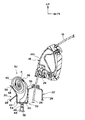
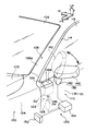
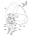
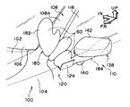
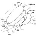
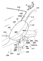
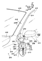
- FIG. 2 is a cross-sectional view taken along line 2-2 of FIG. 1 showing a longitudinal cross-sectional structure of the pedestrian protection airbag device shown in FIG. It is a longitudinal cross-sectional view corresponding to FIG. 2 which shows the state which the pedestrian protection airbag apparatus shown by FIG. 2 started to inflate. It is a perspective view which shows the whole structure of the pedestrian protection airbag apparatus which concerns on 2nd Embodiment. It is a perspective view which shows the state which the pedestrian protection airbag apparatus shown by FIG. 4 act
- FIG. 5 is an enlarged perspective view showing the schematic structure of the door mirror device shown in FIG.
- FIG. 6 It is an expansion perspective view corresponding to FIG. 6 which shows the principal part of the pedestrian protection airbag apparatus which concerns on 3rd Embodiment. It is a perspective view which shows the state of the expansion
- the pedestrian protection airbag apparatus which concerns on 4th Embodiment it is a perspective view which shows the deployment completion state of an airbag. It is a perspective view which shows the whole structure of the pedestrian protection airbag apparatus which concerns on 5th Embodiment. It is a perspective view which shows the state which the pedestrian protection airbag apparatus shown by FIG. 9 act
- FIG. 12 It is a longitudinal cross-sectional view of the pedestrian protection airbag apparatus shown by FIG. It is a perspective view which shows the whole structure of the pedestrian protection airbag apparatus which concerns on 6th Embodiment. It is a perspective view which shows the state which the pedestrian protection airbag apparatus shown by FIG. 12 act
- FIGS. 1-10 A first embodiment of a pedestrian protection airbag device according to the present invention will be described below with reference to FIGS.
- an arrow FR appropriately shown indicates the vehicle front side
- an arrow UP indicates the vehicle upper side
- an arrow IN indicates the vehicle width direction inner side.
- an engine hood 12 is disposed on the front upper surface of the vehicle 10 so as to be openable and closable around a hood hinge.
- a pair of left and right front fender panels 14 are disposed on both side surfaces of the front portion of the vehicle 10.
- a windshield glass 16 is disposed on the rear end side of the engine hood 12 in an inclined state.
- a pair of left and right front side doors 20 and a rear side door are disposed on both sides of the cabin of the vehicle 10.
- the front side door 20 can be moved up and down inside the door main body 22 constituting the lower part of the door, the frame-shaped door frame 24 constituting the upper part of the door, and the door frame 24.
- the door glass 26 is disposed, and a door trim (not shown) lined on the inner side in the vehicle width direction of the door body 22 is configured.
- the door main body 22 includes a door outer panel 28 that is disposed on the outer side in the vehicle width direction and forms a door outer plate, and a door inner panel 29 that is disposed on the inner side in the vehicle width direction and forms a door inner plate. It is configured.
- a pedestrian protection airbag device 30 is disposed on the upper front end side of the door main body 22 described above.
- the pedestrian protection airbag device 30 includes an airbag module 32 disposed in the door main body 22 and an airbag door 34 disposed at a front end portion on the upper edge side (belt line side) of the door outer panel 28. It is configured.
- a rectangular opening 36 in a plan view is formed at a front end portion on the upper edge side of the door outer panel 28, and the opening 36 is closed to be deployable by an airbag door 34 formed in a rectangular shape in a plan view. Has been.
- the airbag module 32 includes a columnar inflator 38 that generates gas when activated, an airbag 40 stored in a folded state above the inflator 38, and a module case 42 in which the airbag 40 is stored. , Including.
- the inflator 38 is arranged with the vehicle vertical direction as the longitudinal direction, and is fixed to the front wall portion of the door inner panel 29 via a bracket.
- a pipe-like gas ejection portion 44 is formed coaxially at the axial center position of the upper end portion of the inflator 38, and the upper end portion of the gas ejection portion 44 and the airbag 40 are mutually connected by a tube-like connecting member 46. It is communicated. As shown in FIG. 3, the airbag 40 is folded by roll folding and stored in the module case 42.
- the airbag 40 is folded by roll folding, but the present invention is not limited to this, and the airbag may be folded by bellows folding, or may be folded by combining bellows folding and roll folding.
- the module case 42 has a box shape and is fixed to the door inner panel 29 via a bracket (not shown).
- the inflator 38 is disposed outside the module case 42, but the present invention is not limited thereto, and both the inflator 38 and the airbag 40 may be accommodated in the module case 42.
- the airbag 40 is sewn by superimposing an inner base fabric portion 50 disposed on the front pillar 18 side and an outer base fabric portion 52 disposed on the opposite side of the front pillar 18. It is comprised by doing.
- the planar developed shape of the outer base fabric portion 52 is set larger than the planar developed shape of the inner base fabric portion 50.
- a planar development shape that combines both the inner base fabric portion 50 and the outer base fabric portion 52 is cut from a single base material, folded at a predetermined fold line, and overlapped into two pieces (hereinafter, this portion).
- folded portion 54 Is referred to as “folded portion 54”), and the outer peripheral portion thereof is further sewn (hereinafter, this portion is referred to as “outer peripheral sewing portion 56”), thereby forming the airbag 40.
- Another method is to cut the inner base fabric portion 50 and the outer base fabric portion 52 from a single base material, overlap the two pieces, and sew the entire circumference of the outer peripheral portion of the two, The bag 40 may be formed.
- the inner base fabric portion 50 and the outer base fabric portion 52 are sewn along the vehicle longitudinal direction at a plurality of locations (two locations in the present embodiment) between the folded portion 54 and the outer periphery sewing portion 56 in FIG. (Hereinafter, this portion is referred to as “intermediate sewing portion 58”).
- this portion is referred to as “intermediate sewing portion 58”.
- the airbag 40 is configured as an assembly of a plurality of cells 60 each formed in a cylindrical shape.
- the plurality of cells 60 are connected in the substantially vertical direction of the vehicle, and each cell 60 is formed in an elongated shape extending in the longitudinal direction of the substantially longitudinal direction of the vehicle (the direction along the front pillar 18).
- the diameter of the cell 60 arranged at the top is the largest, and the length in the longitudinal direction is also long.
- the diameter of the cell 60 arranged at the bottom is the smallest and the length in the longitudinal direction is also short.
- unsewn portions are formed at one or a plurality of locations in the longitudinal direction of each of the intermediate sewing portions 58. By forming this non-sewn portion, a communication hole 62 that connects the cells 60 adjacent to each other is formed.
- the peripheral length L1 of the portion constituted by the inner base fabric portion 50 is more outward. It is set to be shorter than the peripheral length L2 of the portion constituted by the base fabric portion 52.
- the connection part 64 which connects the mutually adjacent cells 60 is arranged offset from the center O of the cell 60 to the front pillar 18 side. Further, the cells 60 adjacent to each other are in contact with each other along the longitudinal direction of the cells 60. With this configuration, a triangular gap 68 having a contact portion 66 between adjacent cells 60 as a vertex and a connecting portion 64 as a base is formed between adjacent cells 60.
- the airbag 40 is folded by roll folding.
- the airbag 40 is roll-folded, it is wound outwardly in the vehicle width direction with the front pillar 18 as the back, that is, the vehicle width with respect to the cell 60 in which the center P of the roll is arranged at the lowermost part of the plurality of cells 60. Wind it so that it is placed outside in the direction.
- the circumferential length L ⁇ b> 1 of the portion configured by the inner base fabric portion 50 is set shorter than the peripheral length L ⁇ b> 2 of the portion configured by the outer base fabric portion 52. Therefore, as a stage before roll folding, the outer base fabric portion 52 of each cell 60 is bellows folded toward the inner base fabric portion 50 side.
- each cell 60 is bellows folded in the direction in which the cells 60 are crushed (see the cell 60 indicated by a two-dot chain line in FIG. 2), and then the airbag 40 in that state is roll-folded. Is folded into a roll.
- the airbag 40 Since the inflator 38 does not operate during normal vehicle travel, the airbag 40 is stored in the front side door 20. From this state, when a collision with a pedestrian occurs, that is, when it is detected that the vehicle has collided with a pedestrian by a detection means such as a pedestrian detection sensor disposed in a front bumper (not shown), the detection signal is sent to the control means. Is output to the airbag ECU. As a result, an ignition current is supplied from the airbag ECU to the ignition device of the inflator 38. As a result, the inflator 38 is activated to generate gas.
- This gas is supplied from the connecting member 46 into the cell 60 disposed at the lowermost part of the airbag 40, and the cell 60 is inflated.
- gas flows into the cell 60 disposed in the intermediate portion from the communication hole 62 formed in the connection portion 64 between the cell 60 disposed in the lowermost portion and the cell 60 disposed in the intermediate portion. Inflates.
- the cell 60 arranged at the uppermost stage is expanded.
- the airbag 40 is inflated to the outside of the front side door 20, and most of the front surface 18A of the front pillar 18 (excluding the upper end portion) is covered. As a result, pedestrians are protected.
- the airbag 40 is configured to include an assembly of a plurality of cells 60 that are deployed along the front pillar 18, and a connection portion 64 that connects the cells 60 adjacent to each other is provided. It is located closer to the front pillar 18 than the center O of the cell 60. For this reason, as shown in FIG. 2, when gas is supplied to the plurality of cells 60, the adjacent cells 60 are pressed against each other, so that the plurality of cells fall to the front pillar side.
- a rotational moment M is applied in which the distance from the connecting portion 64 to the contact portion 66 where the cells 60 are pressed against each other is the arm length a.
- the rotational moment M is a force that presses the cell 60 located on the downstream side in the gas supply direction toward the front pillar 18 side.
- the rotational moment M is sequentially and sequentially repeated with two adjacent cells 60 as a unit.
- the plurality of cells 60 fall to the front pillar 18 side.
- the airbag 40 receives a pedestrian, even if the airbag 40 tends to shift outward in the vehicle width direction, the plurality of cells 60 that are strongly pressed against the front surface 18A of the front pillar 18 are easily Does not move outward in the width direction. Therefore, according to this aspect, when the pedestrian is received, the airbag 40 can be prevented from being displaced (escape) to the outside in the vehicle width direction.
- the airbag 40 is configured by sewing the overlapped upper base fabric portion 50 disposed on the front pillar 18 side and the outer base fabric portion 52 disposed on the opposite side of the front pillar 18. Has been.
- the sewing position (that is, the position of the connecting portion 64) is such that the circumferential length L1 of the portion constituted by the inner base fabric portion 50 is shorter than the circumferential length L2 of the portion constituted by the outer base fabric portion 52. It is possible to define to which side the cell 60 falls (that is, the direction in which the cell 60 falls). Therefore, the configuration is established without any increase in the number of parts. As a result, according to this aspect, the above-described effect can be obtained at low cost.
- the cells 60 are formed in an elongated shape having a direction along the front pillar 18 as a longitudinal direction, and the cells 60 adjacent to each other are in contact with each other along the longitudinal direction of the cells 60. Therefore, as shown in FIG. 1, the cell 60 located on the upstream side in the gas supply direction can support the cell 60 located on the downstream side in the gas supply direction adjacent thereto with a large contact area. Therefore, the inflated airbag 40 can be firmly supported. As a result, according to this aspect, a sufficient reaction force can be maintained when a pedestrian is received.
- the pedestrian protection airbag device 30 is disposed on the door main body portion 22 of the front side door 20, but not limited thereto, the pedestrian protection airbag device is disposed on the door mirror device. You may apply this invention with respect to a thing.
- the airbag 40 is configured to cover at least the lower portion of the front surface 18A of the front pillar 18.
- the present invention is not limited thereto, and the airbag is configured to cover the entire front surface of the front pillar. Also good. The above two points also apply to the embodiments described below.
- an engine hood 102 is disposed on the front upper surface of the vehicle 100 so as to be openable and closable around the hood hinge.
- a pair of left and right front fender panels 104 are disposed on both front side surfaces of the vehicle 100.
- a windshield glass 106 is disposed on the rear end side of the engine hood 102 in an inclined state.
- a pair of left and right front pillars 108 which are vehicle body skeleton members are disposed.
- a pair of left and right front side doors 110 and a rear side door (not shown) are disposed on both sides of the cabin of the vehicle 100.
- the front side door 110 includes a door main body portion 112 constituting a lower portion of the door, a frame-shaped door frame 114 constituting an upper portion of the door, a door glass 116 disposed inside the door frame 114 so as to be movable up and down, a door main body. And a door trim (not shown) lined on the inner side of the portion 112 in the vehicle width direction.
- the door main body 112 includes a door outer panel 118 that is disposed on the outer side in the vehicle width direction and forms a door outer plate, and a door inner panel (not shown) that is disposed on the inner side in the vehicle width direction and forms a door inner plate. It consists of
- a pedestrian protection airbag device 120 is disposed on the upper front end side of the door main body 112 described above.
- the pedestrian protection airbag device 120 includes an airbag module 122 disposed in the door main body 112 and an airbag door 124 disposed at the front edge of the upper edge side (belt line side) of the door outer panel 118. It is configured.
- a rectangular opening 126 in a plan view is formed at a front end portion on the upper edge side of the door outer panel 118, and the opening 126 is closed in a deployable manner by an airbag door 124 formed in a rectangular shape in a plan view. Has been.
- the airbag module 122 includes a cylindrical inflator 128 that generates gas when activated, an airbag 40 (see FIG. 5) stored in a folded state above the inflator 128, and the airbag 40 stored therein.
- the inflator 128 is arranged with the vehicle vertical direction as the longitudinal direction, and is fixed to the front wall portion of the door inner panel via a bracket.
- a pipe-like gas ejection portion 134 is coaxially formed at the axial center position of the upper end portion of the inflator 128, and the upper end portion of the gas ejection portion 134 and the airbag 40 are mutually connected by a tube-like connecting member 136. It is communicated.
- the airbag 40 is the same as that used in the first embodiment described above.
- the airbag 40 is configured to include an assembly of a plurality of cells 60.
- the module case 132 has a box shape and is fixed to the door inner panel via a bracket (not shown).
- the inflator 128 is disposed outside the module case 132, but the present invention is not limited thereto, and both the inflator 128 and the airbag 40 may be accommodated in the module case 132.
- An electric retractable door mirror device 138 is disposed at the upper end of the door body 112 described above.
- the door mirror device 138 is erected on the vehicle rear side of the airbag door 124 in the door main body 112.
- the door mirror device 138 includes a support portion 140 as a non-movable part of the door mirror device fixed to the door main body portion 112, and a door mirror main body portion 142 supported rotatably on the support portion 140. Yes.
- the electrically retractable door mirror device 138 is in a use position where the door mirror main body 142 projects from the front side door 110 outward in the vehicle width direction (FIGS. 4 and 5). 6 and a retracted position (indicated by a two-dot chain line in FIGS. 4 and 6) where the door mirror main body 142 is extended along the upper surface of the lower portion of the front pillar 108. ing. Specifically, as shown in FIG.
- the support part 140 side of the door mirror device 138 is configured by a disk-shaped base part 144 ⁇ / b> A and a cylindrical shaft 144 ⁇ / b> B erected from the shaft core part of the base part 144 ⁇ / b> A.
- the stand 144 is fixed.
- the shaft 144B of the stand 144 is not erected with the vehicle vertical direction as the axial direction, but is erected with the axis inclined at a predetermined angle outward in the vehicle width direction when viewed from the vehicle front side.
- a clutch gear 146 is fixed to the outer periphery of the shaft 144B of the stand 144 so as not to rotate.
- the clutch gear 146 is urged downward in the axial direction by a compression coil spring (not shown) wound around the shaft 144B. For this reason, the clutch gear 146 cannot rotate around the shaft 144B. However, when an overload is applied, the clutch gear 146 moves in the axial direction and interrupts a driving force transmission path from a driving motor 148 described later.
- a drive motor 148 is disposed in the electric storage unit.
- An output gear 150 is fixed to the output shaft of the drive motor 148.
- the output gear 150 and the clutch gear 146 are connected via a reduction mechanism (not shown).
- a pre-crash sensor 152 as a collision prediction sensor is disposed at the center of a front bumper (not shown) of the vehicle 100 described above.
- the pre-crash sensor 152 detects a collision with a collision object by irradiating a millimeter wave radar to the front side of the vehicle.
- the pre-crash sensor 152 is connected to an airbag ECU 154 as a control device disposed below the console box of the vehicle 100. Further, the airbag ECU 154 is connected to an ignition device (not shown) disposed on the shaft core portion of the inflator 128.
- the airbag ECU 154 is also connected to a drive motor 148 of the door mirror device 138 and controls its operation.
- the door mirror main body 142 extends from the upper front end side of the front side door 110 to the outside in the vehicle width direction as illustrated by a solid line in FIG.
- the door mirror main body 142 rotates around the axis 144B and is folded so as to follow the longitudinal direction of the front pillar 108 as shown by a two-dot chain line in FIG.
- the door mirror main body 142 projects from the upper front end side of the front side door 110 to the outside in the vehicle width direction.
- a detection signal is output to the airbag ECU 154.
- the airbag ECU 154 determines whether or not a collision with a pedestrian is unavoidable, and if it is determined to be unavoidable, an ignition current is supplied to the ignition device of the inflator 128.
- the inflator 128 of the airbag module 122 is activated to generate gas.
- This gas is supplied into the airbag 40 stored in a folded state.
- the airbag 40 is inflated, and the airbag door 124 is deployed outward in the vehicle width direction by the inflation pressure as shown in FIG.
- the airbag 40 is inflated to the outside of the front side door 110, and most of the front surface 108A (the range excluding the upper end portion) of the front pillar 108 is covered. As a result, pedestrians are protected.
- the airbag ECU 154 drives the drive motor 148 of the door mirror device 138 in reverse.
- the door mirror main body 142 is forcibly rotated from the use position (shown by the solid line) to the storage position (shown by the two-dot chain line) around the shaft 144B. That is, the door mirror main body 142 is forcibly moved from the use position to the storage position.
- the rear side 130 ⁇ / b> A (the whole) of the airbag 40 on the outer side in the vehicle width direction is supported from the outer side in the vehicle width direction by the door mirror main body 142.
- the door mirror main body 142 exists as a “wall” on the outer side of the airbag 40 in the vehicle width direction. Accordingly, the airbag 40 is held on the front surface 108A of the front pillar 108 in a stable state. As a result, when the airbag 40 receives a pedestrian, even if the airbag 40 tends to shift outward in the vehicle width direction, the door mirror main body 142 becomes a wall and the airbag 40 moves outward in the vehicle width direction. Suppress. Therefore, according to the pedestrian protection airbag device 120 according to the present embodiment having the above-described configuration, it is possible to suppress the airbag 40 from being displaced (escaped) outward in the vehicle width direction when the pedestrian is received.
- the effects described in the first embodiment can be obtained in addition to the above-described effects. Therefore, according to this embodiment, when the pedestrian is received, the airbag 40 can be further suppressed from being displaced (escape) to the outside in the vehicle width direction.
- the door mirror device 138 is configured as a so-called electric retractable door mirror device including a drive motor 148.
- the door mirror posture changing means is configured as an airbag ECU 154 that controls the driving of the drive motor 148.
- the driving motor 148 is automatically driven by the airbag ECU 154, and the door mirror main body 142 is forcibly moved from the use position to the storage position.
- the door ECU main body 142 is forcibly moved from the use position to the storage position by the airbag ECU 154. Therefore, it is necessary to add a new member or the like as the door mirror posture changing means.
- the intended purpose can be achieved without increasing the cost and enlarging the vehicle mounting space.
- the door mirror main body 142 when the collision is predicted by the pre-crash sensor 152, the door mirror main body 142 is controlled to be forcibly moved from the use position to the storage position and the inflator 128 is operated.
- the collision prediction sensor front collision prediction
- the door mirror main body is forcibly moved from the use position to the storage position, and a collision detection sensor provided separately from the collision prediction sensor
- the inflator When a collision with a pedestrian is detected (frontal collision), the inflator is activated.
- a collision detection sensor does not detect a collision with a pedestrian (frontal collision avoidance), the inflator is not activated.
- the door mirror main body may be controlled to automatically return from the storage position to the use position.
- the second embodiment is characterized in that a push-up mechanism 164 composed of a cylinder 160, a piston 162, and the like is provided in the door mirror device 138 described in the first embodiment.
- a cylindrical cylinder 160 whose both ends in the axial direction are sealed with disc-shaped caps 166 is disposed in the support portion 140 of the door mirror device 138.
- One end of a tube 168 as a communication member is connected to the lower end of the cylinder 160.
- the other end of the tube 168 is connected to a part that can take in the gas generated by the inflator 128, such as the base of the inflator 128 or the airbag 40.
- a piston 162 is disposed in the cylinder 160 so as to be movable in the axial direction of the cylinder 160. Since the piston 162 is disposed in the cylinder 160, the chamber in the cylinder 160 is separated into a first chamber 170 connected to the tube 168 and a second chamber 172 not connected to the tube 168. Has been.
- a lower end portion of a piston rod 174 as a push-up portion is connected to the shaft core portion of the piston 162.
- the piston rod 174 is integrated with the piston 162.
- An upper end portion of the piston rod 174 passes through a cap 166 fixed to an end portion of the cylinder 160, and a hemispherical pressing portion 176 is integrally formed at the penetrating end portion. Therefore, the pressing part 176 is also a part of the pushing-up part.
- the pressing portion 176 is normally held on the cap 166 side and is opposed to the inner peripheral surface of the hemispherical concave portion 179 formed in the door mirror visor 178 of the door mirror main body portion 142 at the use position. Has been.
- the cylinder 160, the tube 168, the piston 162, and the piston rod 174 correspond to the door mirror posture changing means in the present invention.
- the pressing portion 176 of the piston rod 174 is opposed to the inner peripheral surface of the recess 179 formed in the door mirror visor 178 of the door mirror main body portion 142, the pressing portion 176 moves the door mirror when the piston rod 174 moves.
- the main body 142 is pressed in the direction of arrow A in FIG. As a result, the door mirror main body 142 is forcibly moved from the use position (shown by the solid line in FIG. 7) to the storage position (shown by the two-dot chain line in FIG. 7).
- the airbag 40 is supported from the outside in the vehicle width direction by the door mirror main body 142.
- the door mirror main body 142 exists as a “wall” on the outer side of the airbag 40 in the vehicle width direction. Accordingly, the airbag 40 is held on the front surface 108A of the front pillar 108 in a stable state.
- the door mirror main body 142 becomes a wall and the airbag 40 moves outward in the vehicle width direction. Can be suppressed. Therefore, according to the pedestrian protection airbag device 120 according to the present embodiment having the above-described configuration, it is possible to suppress the airbag 40 from being displaced (escaped) outward in the vehicle width direction when the pedestrian is received.
- the door mirror main body 142 is forcibly moved from the use position to the storage position in a state of being almost completely mechanically connected, so that the reliability is high. .
- the intended purpose can be reliably achieved.
- the pressing portion 176 is disposed opposite to the inner peripheral surface of the concave portion 179 formed in the door mirror visor 178.
- the present invention is not limited to this, and the pressing portion 176 contacts the inner peripheral surface of the concave portion 179. You may arrange in a state.
- the third embodiment is characterized in that the shape of the airbag 180 is changed to a bifurcated shape.
- the airbag 180 is branched from an airbag main body 182 that covers most of the front surface 108A of the front pillar 108 when inflated and deployed, and a lower portion (root portion) of the airbag main body 182. It is formed in a bifurcated shape including an airbag branching portion 184 as an airbag posture changing means extending rearward.
- the capacity of the airbag main body 182 is larger than the capacity of the airbag branch 184, and therefore the airbag main body 182 is formed larger than the airbag branch 184.
- the airbag branching portion 184 is formed so as to sink into the lower side of the door mirror main body 142 at the initial stage when the airbag 180 is inflated and deployed.
- the airbag body 182 has a cell structure including a plurality of cells 60 as in the first embodiment.
- the airbag 180 includes an airbag main body 182 for protecting a pedestrian and an airbag branching section 184 that functions as a door mirror posture changing means. For this reason, when the airbag 180 is inflated and deployed, both the airbag body 182 and the airbag branch 184 are inflated and deployed. That is, the airbag branch portion 184 is inflated and deployed under the door mirror main body portion 142, and the airbag main body portion 182 is inflated and deployed so as to cover most of the front surface 108A of the front pillar 108. When the airbag main body 182 bulges toward the front surface 108 ⁇ / b> A of the front pillar 108, the door mirror main body 142 is forcibly pushed up from the use position to the storage position by the airbag branch 184.
- the door mirror main body 142 is held in the retracted position and supports the airbag main body 182 from the outside in the vehicle width direction.
- the door mirror main body 142 is present as a “wall” outside the airbag main body 182 in the vehicle width direction.
- the airbag main body 182 is held on the front surface 108A of the front pillar 108 in a stable state.
- the vehicle of the airbag main body 182 becomes the door mirror main body 142 as a wall. Movement to the outside in the width direction can be suppressed. Therefore, according to the pedestrian protection airbag device 120 according to the present embodiment having the above-described configuration, it is possible to suppress the airbag main body portion 182 from shifting (escape) outward in the vehicle width direction when the pedestrian is received. .
- the present embodiment follows the configuration of the first embodiment, the effects described in the first embodiment can be obtained in addition to the above-described effects. Therefore, according to this embodiment, when the pedestrian is received, the airbag 40 can be further suppressed from being displaced (escape) to the outside in the vehicle width direction.
- the door mirror main body 142 is moved from the use position to the storage position only by changing the shape of the airbag 180 and making the output of the inflator 128 commensurate with the capacity of the airbag 180. It can be forcibly moved. Therefore, according to the present embodiment, the intended purpose can be achieved with a minimum design change of the airbag module 122.
- an engine hood 202 is disposed on the front upper surface of the vehicle 200 so as to be openable and closable around the hood hinge.
- a pair of left and right front fender panels 204 are disposed on both front side surfaces of the vehicle 200.
- a windshield glass 206 is disposed on the rear end side of the engine hood 202 in an inclined state.
- a pair of left and right front pillars 208 which are vehicle body skeleton members, are disposed.
- a pair of left and right front side doors 210 and a rear side door (not shown) are disposed on both sides of the cabin of the vehicle 200.
- the front side door 210 includes a door main body 212 that forms the lower part of the door, a frame-shaped door frame 214 that forms the upper part of the door, a door glass 216 that can be moved up and down inside the door frame 214, and a door main body And a door trim (not shown) lined on the inner side of the portion 212 in the vehicle width direction. Furthermore, the door main body 212 is arranged on the outer side in the vehicle width direction to constitute a door outer plate 218 and the door inner panel 219 arranged on the inner side in the vehicle width direction to constitute a door inner plate (see FIG. 11). And.
- a pedestrian protection airbag device 220 is disposed on the upper front end side of the door main body 212 described above.
- the pedestrian protection airbag device 220 includes an airbag module 222 disposed in the door body 212, and an airbag door 224 disposed at the front edge of the upper edge side (belt line side) of the door outer panel 218. It is configured.
- a rectangular opening 226 in a plan view is formed at a front end portion on the upper edge side of the door outer panel 218, and the opening 226 is closed in a deployable manner by an airbag door 224 formed in a rectangular shape in a plan view. Has been.
- the airbag module 222 includes a cylindrical inflator 228 that generates gas when activated, an airbag 230 stored in a folded state above the inflator 228, and a module case 232 in which the airbag 230 is stored. , Including.
- the inflator 228 is arranged with the vehicle vertical direction as the longitudinal direction, and is fixed to the front wall of the door inner panel 219 via a bracket.
- a pipe-like gas ejection portion 234 is formed coaxially at the axial center position of the upper end portion of the inflator 228, and the upper end portion of the gas ejection portion 234 and the airbag 230 are mutually connected by a tubular connection member 236. It is communicated.
- the module case 232 has a box shape and is fixed to the door inner panel 219 via a bracket (not shown).
- the inflator 228 is disposed outside the module case 232.
- the present invention is not limited to this, and both the inflator 228 and the airbag 230 may be accommodated in the module case 232.
- a door mirror device 238 including a support portion 240 and a door mirror body portion 242 is disposed at the upper end portion of the door body portion 212 described above.
- the door mirror device 238 is erected on the vehicle rear side of the airbag door 224 in the door main body 212.
- the airbag 230 in the inflated and deployed state, the airbag 230 includes an airbag main body 260 disposed on the front surface 208 ⁇ / b> A of the front pillar 208, and a vehicle lower side from the lower portion of the airbag main body 260. And a tube-like support portion 262 extending to the outside.
- the airbag main body 260 is a portion corresponding to the airbag 40 of the first embodiment described above. Therefore, the airbag main body 260 is configured as an assembly of a plurality of cells 60.
- the support part 262 is formed in a cylindrical shape.
- a circular communication hole 264 is formed at a position where the upper end portion 262A of the support portion 262 is connected to the cell 60 disposed at the lowermost portion of the airbag main body portion 260.
- the upper end portion 262A of the support portion 262 is bent outward in the radial direction of the support portion 262 and attached to the outer peripheral portion of the communication hole 264 of the cell 60 by sewing.
- the lower end portion 262B of the support portion 262 is closed and fixed to the bottom portion 232A of the module case 232. That is, the airbag main body 260 is not fixed to the module case 232 but only stored in a folded state in the module case 232, and the lower end 262 B of the support 262 is fixed to the bottom 232 A of the module case 232. As a result, the airbag 230 is supported by the module case 232. Further, a connection member 236 connected to the gas ejection portion 234 of the inflator 228 is passed through the lower end portion 262B of the support portion 262.
- a fixing plate formed in a ring shape and stud bolts standing at predetermined intervals in the circumferential direction is used as a method of fixing the lower end portion 262B of the support portion 262 to the bottom portion 232A of the module case 232. It is possible to apply a configuration in which a stud bolt is passed through the bottom portion 232A of the module case 232 and nuts are tightened on the back surface side of the bottom portion 232A of the module case 232 in advance.
- the lower end portion 262B of the support portion 262 is not necessarily closed, and the lower end portion 262B may have an open shape, and the peripheral edge portion may be bent inward and fixed with a fixing plate.
- the gas ejection part 234 of the inflator 228 is inserted from the through hole formed in the bottom part 232A of the module case 232 so as to protrude inward of the lower end part 262B of the support part 262, and the inflator 228 is fixed to the fixing plate. You may make it tighten together with a stud bolt. By doing so, the connecting member 236 is not necessary.
- a pre-crash sensor 252 that functions as a collision prediction sensor is disposed at the center of a front bumper (not shown) of the vehicle 200 described above.
- the pre-crash sensor 252 detects a collision with a collision object by irradiating the front side of the vehicle with a millimeter wave radar.
- the pre-crash sensor 252 is connected to an airbag ECU 254 that functions as a control device disposed below the console box of the vehicle 200. Further, the airbag ECU 254 is connected to an ignition device (not shown) disposed on the shaft core portion of the inflator 228.
- a vehicle speed sensor 266 that detects the traveling speed of the vehicle 200 is connected to the airbag ECU 254.
- the inflator 228 does not operate because the pre-crash sensor 152 does not detect a collision with a collision object except when a collision is predicted. For this reason, the airbag 230 maintains the state stored in the front side door 210.
- a detection signal is output to the airbag ECU 154.
- the vehicle speed sensor 266 detects the traveling speed of the vehicle 200 and outputs it to the airbag ECU 154.
- the airbag ECU 154 obtains the speed at that time based on the detection signal from the vehicle speed sensor 266, and when the collision with the colliding body is predicted by the pre-crash sensor 152 at a predetermined vehicle speed (for example, 25 km / h) or more. Then, an ignition current is applied to the ignition device of the inflator 228.
- the inflator 228 of the airbag module 222 is activated to generate gas.
- This gas is supplied into the airbag 230 stored in a folded state. Specifically, it is first ejected into the tubular support portion 262. Therefore, as shown in FIGS. 10 and 11, the support portion 262 is erected in a columnar shape before the airbag main body portion 260 is inflated or at the beginning of the inflation, and the airbag main body portion 260 is attached to the front pillar 208. Lift the vehicle outward in the width direction.
- the airbag main body 260 is inflated and deployed (in addition, the manner of inflating and deploying the airbag main body 260 is the same as that of the first embodiment described above, and the airbag main body 260 is inflated and deployed sequentially from the cell 60 arranged at the bottom. ), Most of the front surface 208A of the front pillar 208 (the range excluding the upper end portion) is covered. As a result, pedestrians are protected.
- the communication hole 264 formed in the airbag main body 260 may be closed with a circular partition wall sewn with a tear seam that is broken at a predetermined inflation pressure. If the communication hole 264 is closed by the partition wall, the effect of the rising of the support portion 262 is obtained.
- the airbag main body 260 is inflated and deployed from a position closer to the front surface 208A of the front pillar 208. Accordingly, the time until the airbag 230 is inflated and deployed on the front surface 208A of the front pillar 208 is shorter than in the configuration in which the airbag starts inflating and deploying from within the front side door. That is, according to the present embodiment, it is possible to shorten the time from when the inflator 228 is activated until the airbag 230 is inflated and deployed on the front surface 208A of the front pillar 208.
- the present embodiment follows the configuration of the first embodiment, the effects described in the first embodiment can be obtained in addition to the above-described effects. Therefore, according to the present embodiment, it is possible to shorten the time from when the inflator is activated until the airbag is inflated and deployed on the front surface of the front pillar, and when the pedestrian is received, the airbag 40 It is possible to suppress shifting (escape) to the outside in the direction.
- the moving means for lifting the airbag main body 260 is established by the tube-like support portion 262, compared to the case where the moving means is established using another mechanical mechanism, The structure can be simplified and there is no need to secure the installation space for the parts. Therefore, it is possible to shorten the time from when the inflator 228 is operated with a simple configuration until the airbag 230 is inflated and deployed on the front surface 208A of the front pillar 208.
- the pedestrian protection airbag device 220 is activated at the time of collision prediction.
- the present invention is not limited to this, and the pedestrian protection airbag device may be activated at the time of collision.
- the sixth embodiment is characterized in that the moving means is realized by a mechanical configuration.
- a rack bar 270 that is elongated along the vehicle vertical direction is fixed to the side surface of the lower end portion of the module case 232 of the airbag module 222.
- a drive motor 272 is disposed on the front side of the rack bar 270 in the vehicle.
- the drive motor 272 is fixed to the door inner panel 219 of the door main body 212 of the front side door 210 via a bracket (not shown).
- a pinion 276 is fixed to the tip of the output shaft 274 of the drive motor 272.
- the pinion 276 is arranged in mesh with the rack bar 270. Therefore, when the drive motor 272 is driven and rotated, the rack bar 270 moves up and down via the pinion 276.
- the pinion 276 is directly meshed with the rack bar 270, but a reduction mechanism including a plurality of reduction gears may be interposed between the pinion 276 and the rack bar 270.
- the position of the module case 232 illustrated by the solid line in FIG. 12 is the storage position of the module case 232 (airbag 230), and the position of the module case 232 illustrated by the two-dot chain line is the module case 232 (airbag 230).
- Ascending position that is, the outer position of the front pillar 208 in the vehicle width direction.
- the inflator 228 is fixed in a state of being hung from the bottom of the module case 232. Therefore, the inflator 228 is not fixed to the door inner panel 219, and can move integrally with the module case 232.
- the rack bar 270 corresponds to the “lifting mechanism” in the present invention
- the pinion 276 (in the case where the speed reduction mechanism is provided, the pinion 276 and the speed reduction mechanism) is the “driving force transmission mechanism” in the present invention. Is equivalent to.
- a stop signal is output from the airbag ECU 254 to the drive motor 272.
- the inflator 228 is operated by the airbag ECU 254.
- the airbag 230 is inflated, and the airbag door 224 is deployed outward in the vehicle width direction by the inflation pressure.
- the airbag 230 covers most of the front surface 208A of the front pillar 208 (the range excluding the upper end). As a result, pedestrians are protected.
- the moving means is configured to include the drive motor 272, the pinion 276, and the rack bar 270, the number of parts increases, but the module case 232 is raised from the retracted position by mechanical operation ( The front pillar 208 can be moved (lifted up) to the outer side in the vehicle width direction). For this reason, the position at the start of deployment of the airbag 230 is difficult to shift. As a result, it is possible to suppress or prevent the inflation / deployment position of the airbag 230 on the front surface 208 ⁇ / b> A of the front pillar 208 from varying, and as a result, pedestrian protection accuracy by the airbag 230 can be enhanced.
- the entire airbag module 222 including the airbag 230, the module case 232, and the inflator 228 is configured to rise.
- 230 should rise.
- the inflator 228 and the airbag 230 may be connected with a flexible tube with a surplus length, and the inflator 228 may be fixed to the door inner panel 219 with a bracket. In this case, the inflator 228 does not rise, and the module case 232 and the airbag 230 stored therein are raised.
- the module case 232 is lifted by the rack and pinion.
- the present invention is not limited to this, and other mechanisms may be used.
- the module case 232 may be lifted using a parallel link mechanism.
- the drive motor 272 when a collision is predicted by the pre-crash sensor 252, the drive motor 272 is driven to move the module case 232 from the storage position to the ascending position and the inflator 228 is operated.
- the collision prediction sensor predicts a collision with a collision object (when predicting a frontal collision)
- the drive motor is driven to forcibly move the module case from the retracted position to the raised position.
- the collision detection sensor provided separately detects the collision with the pedestrian (front collision)
- the inflator is activated and the collision detection sensor does not detect the collision with the pedestrian (when avoiding the front collision).
- the drive motor is driven in reverse to move the module case from the raised position to the retracted position. It may be controlled so as to be automatically restored.
Landscapes
- Engineering & Computer Science (AREA)
- Mechanical Engineering (AREA)
- Air Bags (AREA)
Abstract
歩行者を受け止めたときにエアバッグが車両幅方向外側へずれる(逃げる)ことを抑制する。 フロントサイドドア(20)内にはエアバッグモジュール(32)が配設されている。エアバッグモジュール(32)は、モジュールケース(42)内に折り畳み状態で格納されたエアバッグ(40)を備えている。エアバッグ(40)は、各々円筒状に形成された複数のセル(60)の集合体として構成されている。各セル(60)の内側基布部(50)の周長L1は、外側基布部(52)の周長L2よりも短く設定されている。このため、互いに隣接するセル(60)同士を連結する連結部位(64)は、当該セル(60)の中心Oよりもフロントピラー(18)側に位置されている。
Description
本発明は、歩行者との衝突時又は衝突予測時に車外にエアバッグが膨張展開される歩行者保護エアバッグ装置に関する。
下記特許文献1(特開2009-006957号公報)には、歩行者との衝突時にフロントピラーの前面にエアバッグを膨張展開させる技術が開示されている。簡単に説明すると、この先行技術では、ドアフレームの前縁部又はドアミラーベース部にエアバッグモジュールが格納されている。歩行者と衝突すると、インフレータが作動して折り畳み状態のエアバッグ内へガスが供給される。その結果、フロントピラーの前面にエアバッグが膨張展開されるようになっている。
さらに、上記先行技術では、膨張本体部の車両幅方向外側に小さめの支持膨張部を設け、エアバッグの膨張展開時に支持膨張部の一部をドアミラー本体の車両幅方向の内側面に当接支持させるようになっている。これにより、展開後のエアバッグがフロントピラーの前面に対して車両幅方向外側にずれることを防止している。
特開2009-006957号公報
特開2009-023600号公報
しかしながら、上記先行技術に開示された構成による場合、以下に説明する点で改善の余地がある。
すなわち、上記エアバッグはフロントピラーの車両幅方向外側からフロントピラーの前面に膨張展開する構造であるため、本来的にエアバッグは車両幅方向外側へずれやすい(逃げやすい)。このため、上記先行技術のようにサイドドアから車両幅方向外側に張出されたドアミラー本体における車両幅方向の内側面に、支持膨張部の一部を当接させただけでは、エアバッグが車両幅方向外側へずれるのを抑制するのに不十分である。従って、上記先行技術は、この点において改善の余地がある。
本発明は上記事実を考慮し、歩行者を受け止めたときにエアバッグが車両幅方向外側へずれる(逃げる)ことを抑制することができる歩行者保護エアバッグ装置を得ることが目的である。
第1の態様に係る歩行者保護エアバッグ装置は、サイドドア内又はドアミラー装置内に設けられ、作動することによりガスを発生するインフレータと、折り畳み状態で格納されると共に前記インフレータからガスが供給されることにより前記サイドドア外又はドアミラー装置外へ膨出してフロントピラーの前面の少なくとも下部を覆うように展開されるエアバッグと、を備え、前記エアバッグは、前記フロントピラーに沿って展開される複数のセルの集合体を含んで構成されており、さらに、互いに隣接するセル同士を連結する連結部位が、当該セルの中心よりも前記フロントピラー側に位置されている。
第2の態様に係る歩行者保護エアバッグ装置は、第1の態様において、前記エアバッグは、前記フロントピラー側に配置された内側基布部と前記フロントピラーと反対側に配置された外側基布部とを重ね合わせて縫製することにより構成されており、前記セルにおいて、前記内側基布部で構成された部分の周長が、前記外側基布部で構成された部分の周長よりも短く設定されている、ことを特徴としている。
第3の態様に係る歩行者保護エアバッグ装置は、第1又は第2の態様において、前記セルは、前記フロントピラーに沿った方向を長手方向とする細長形状に形成されており、さらに、互いに隣接するセル同士が、当該セルの長手方向に沿って接触している、ことを特徴としている。
第4の態様に係る歩行者保護エアバッグ装置は、第1~第3のいずれか一つの態様において、使用時にはドアミラー本体部がサイドドアの上部前端側から車両幅方向外側へ張出されると共に格納時にはドアミラー本体部が軸回りに回動してフロントピラーの長手方向に添うように畳まれるドアミラー装置を備えた車両に適用され、さらに、衝突時又は衝突予測時に、前記ドアミラー本体部を使用位置から格納位置へ強制的に移動させるドアミラー姿勢変更手段を備えている、ことを特徴としている。
第5の態様に係る歩行者保護エアバッグ装置は、第4の態様において、第1~第3のいずれか一つの態様において、前記ドアミラー装置は、前記ドアミラー本体部内に設けられ駆動することにより当該ドアミラー本体部を前記軸回りに回動させる駆動モータを含んで構成されており、前記ドアミラー姿勢変更手段は、前記衝突予測時に当該駆動モータを駆動させて前記ドアミラー本体部を使用位置から格納位置へ強制的に移動させる制御装置である、ことを特徴としている。
第6の態様に係る歩行者保護エアバッグ装置は、第4の態様において、前記ドアミラー姿勢変更手段は、前記サイドドア又はドアミラー装置の非可動部分に固定されたシリンダと、前記インフレータと前記シリンダとを連通し、当該インフレータで発生したガスの一部を当該シリンダ内へ供給する連通部材と、前記インフレータ内に軸方向移動可能に収容され、前記シリンダ内の室を前記連通部材が接続された側の第1室と、前記連通部材が接続されない側の第2室とに区画するピストンと、一端部が前記ピストンに固定されると共に、前記ドアミラー本体部を使用位置から格納位置へ強制的に移動させる押圧力を当該ドアミラー本体部に付与可能な位置に他端部が配置された押し上げ部と、を含んで構成されている、ことを特徴としている。
第7の態様に係る歩行者保護エアバッグ装置は、第4の態様において、前記エアバッグは、前記フロントピラーの前面の少なくとも下部を覆うように膨張展開されるエアバッグ本体部と、当該エアバッグ本体部から枝分かれして前記ドアミラー本体部の下側で膨張展開されるエアバッグ分岐部と、を含んで構成されており、前記ドアミラー姿勢変更手段は、当該エアバッグ分岐部として構成されている、ことを特徴としている。
第8の態様に係る歩行者保護エアバッグ装置は、第1~第3のいずれか一つの態様において、衝突時又は衝突予測時に、前記エアバッグを前記サイドドア内又はドアミラー装置内の格納位置から前記フロントピラーの車両幅方向外側位置まで移動させる移動手段を備えている、ことを特徴としている。
第9の態様に係る歩行者保護エアバッグ装置は、第8の態様において、前記移動手段は、一端部が前記インフレータに接続されると共に他端部が前記エアバッグの下部と連通され、前記インフレータからのガスが供給されると前記フロントピラーに向って延び上がるチューブ状の押し上げ部を含んで構成されている、ことを特徴としている。
第10の態様に係る歩行者保護エアバッグ装置は、第8の態様において、前記移動手段は、前記衝突予測時に作動される駆動モータと、少なくとも前記エアバッグを含んで構成されたエアバッグモジュールを格納位置から前記フロントピラーの車両幅方向外側位置まで上昇させる持ち上げ機構と、前記駆動モータの駆動力を前記持ち上げ機構に伝達する駆動力伝達機構と、を含んで構成されている、ことを特徴としている。
第1の態様によれば、インフレータが作動する前の状態では、ガスは発生しないので、エアバッグは折り畳み状態で格納されている。この状態から、インフレータが作動すると、インフレータからガスが発生する。発生したガスは、折り畳み状態のエアバッグ内へ供給される。これにより、エアバッグは、サイドドア外又はドアミラー装置外へ膨出される。その結果、フロントピラーの前面の少なくとも下部がエアバッグによって覆われる。これにより、歩行者が保護される。
ここで、本態様では、上記エアバッグがフロントピラーに沿って展開される複数のセルの集合体を含んで構成されていると共に、互いに隣接するセル同士を連結する連結部位がセルの中心よりもフロントピラー側に位置されている。このため、複数のセルにガスが供給されると、互いに隣接するセル同士が押し合うことで複数のセルはフロントピラー側へ倒れ込む。つまり、隣接する二個のセルに着目して考えると、ガス供給方向の下流側に位置するセルには、ガス供給方向の上流側に位置するセルとの連結部位を中心とし、当該連結部位からセル同士が押し合う接触部位までの距離をアーム長とする回転モーメントが作用する。この回転モーメントは、ガス供給方向の下流側に位置するセルをフロントピラー側へ押し付ける力である。そして、この回転モーメントが、隣接する二個のセルを一単位として連鎖的に順次繰り返される。
その結果、上記のように複数のセルは、フロントピラー側へ倒れ込む。これにより、エアバッグが歩行者を受け止めた際に、当該エアバッグが車両幅方向外側へずれようとしても、フロントピラーの前面に強く押し付けられた複数のセルは容易には車両幅方向外側へ移動しない。
第2の態様によれば、上記エアバッグは、フロントピラー側に配置された内側基布部とフロントピラーと反対側に配置された外側基布部とを重ね合わせて縫製することにより構成されている。
ここで、本態様では、セルにおいて内側基布部で構成された部分の周長が、外側基布部で構成された部分の周長よりも短く設定されているので、セル内にガスが供給されてセルが膨張すると、そのセルは周長が短い方へ倒れ込む。換言すれば、内側基布部で構成された部分の周長が外側基布部で構成された部分の周長よりも短くなるように縫製位置(即ち、連結部位の位置)を決めるだけでよい。従って、何ら部品点数が増加することなく、構成が成立する。
第3の態様によれば、セルがフロントピラーに沿った方向を長手方向とする細長形状に形成されており、さらに互いに隣接するセル同士がセルの長手方向に沿って接触している。このため、ガス供給方向の上流側に位置するセルが、これに隣接するガス供給方向の下流側に位置するセルを大きな接触面積で支えることができる。従って、膨張展開したエアバッグをしっかりと支えることができる。
第4の態様では、使用時にはドアミラー本体部がサイドドアの上部前端側から車両幅方向外側へ張出されると共に格納時にはドアミラー本体部が軸回りに回動してフロントピラーの長手方向に添うように畳まれるドアミラー装置を備えた車両が適用対象となる。
ここで、車両走行時において、衝突時又は衝突予測時以外の場合には、ドアミラー本体部は使用位置に保持される。このため、ドアミラー本体部は、サイドドアの上部前端側から車両幅方向外側へ張出されている。この状態から、衝突時又は衝突予測時になると、サイドドア内又はドアミラー装置内に設けられたエアバッグモジュールのインフレータが作動してガスを発生する。このガスは折り畳み状態で格納されたエアバッグ内へ供給される。このため、エアバッグがサイド外又はドアミラー装置外へ膨出されて、フロントピラーの前面の少なくとも下部が覆われる。その結果、歩行者が保護される。
さらに、衝突時又は衝突予測時になると、ドアミラー姿勢変更手段が作動される。これにより、ドアミラー本体部は使用位置から格納位置に強制的に移動される。その結果、エアバッグは、ドアミラー本体部によって車両幅方向外側から支持される。換言すれば、ドアミラー本体部がエアバッグの車両幅方向外側に「壁」として存在する。これにより、エアバッグは安定した状態でフロントピラーの前面に保持される。その結果、エアバッグが歩行者を受け止めた際に、当該エアバッグが車両幅方向外側へずれようとしても、ミラー本体部が壁となってエアバッグの車両幅方向外側への移動を抑制する。
第5の態様によれば、ドアミラー装置は、駆動モータを含んで構成された所謂電動格納式ドアミラー装置として構成されている。また、ドアミラー姿勢変更手段は、この駆動モータの駆動を制御する制御装置として構成されている。衝突予測時になると、制御装置によって駆動モータが自動的に駆動され、ドアミラー本体部は使用位置から格納位置に強制的に移動される。
このように本態様によれば、衝突予測時に制御装置によってドアミラー本体部が使用位置から格納位置へ強制的に移動される構成としたので、ドアミラー姿勢変更手段として新たな部材等を追加する必要がなく、エアバッグモジュールを設計変更する必要もない。このため、部品点数が増加せず、車両搭載スペースを拡大する必要もない。
第6の態様によれば、インフレータが作動すると、ガスの一部が連通部材を介してシリンダの第1室に供給される。このため、第1室の圧力が高まり、第1室と第2室とを区画しているピストンが第2室を圧縮する方向へシリンダ内を移動する。ピストンには押し上げ部の一端部が固定されているため、ピストンがシリンダ内を軸方向移動すると、それに伴って押し上げ部材も同一方向へ移動する。押し上げ部材の他端部はドアミラー本体部における所定位置(即ち、ドアミラー本体部を使用位置から格納位置へ移動させる押圧力をドアミラー本体部に付与可能な位置)に配置されているため、押し上げ部材が移動すると、他端部によってドアミラー本体部が押圧される。これにより、ドアミラー本体部が使用位置から格納位置へ強制的に移動される。
このように本態様によれば、部品点数が増加するものの、完全に又はほぼ完全に機械的に連結された状態でドアミラー本体部を使用位置から格納位置へ強制的に移動させることができるので、信頼性が高い。
第7の態様によれば、インフレータが作動すると、エアバッグ内にガスが供給される。ここで、本態様では、エアバッグが歩行者を保護するためのエアバッグ本体部とドアミラー姿勢変更手段として機能するエアバッグ分岐部とを含んで構成されている。このため、エアバッグが膨張展開するときには、エアバッグ本体部とエアバッグ分岐部の両方が膨張展開される。すなわち、エアバッグ分岐部にあってはドアミラー本体部の下側で膨張展開され、エアバッグ本体部にあってはフロントピラーの前面の少なくとも下部を覆うように膨張展開される。そして、エアバッグ本体部がフロントピラーの前面側へ向けて膨出していく際に、エアバッグ分岐部によってドアミラー本体部が使用位置から格納位置側へ強制的に押し上げられる。これにより。ドアミラー本体部は格納位置に保持されて、エアバッグ本体部を車両幅方向外側から支える。
このように本態様によれば、エアバッグの形状を変更すると共に、インフレータの出力を当該エアバッグの容量に見合ったものにするのみで、ドアミラー本体部を使用位置から格納位置へ強制的に移動させることができる。
第8の態様によれば、衝突時又は衝突予測時になると、移動手段によってエアバッグがサイドドア内又はドアミラー装置内の格納位置からフロントピラーの車両幅方向外側位置まで移動される。このため、エアバッグはフロントピラーの前面により近い位置から膨張展開されることになる。従って、サイドドア内又はドアミラー装置内からエアバッグが膨張展開を開始する構成に比し、エアバッグがフロントピラーの前面に膨張展開するまでの時間が短くなる。
第9の態様によれば、移動手段が一端部がインフレータに接続されると共に他端部がエアバッグの下部と連通されたチューブ状の押し上げ部を含んで構成されているため、衝突時又は衝突予測時にインフレータからガスが発生すると、最初に押し上げ部が膨張してフロントピラーに向って延び上がる。そして、チューブがフロントピラーの前面の車両幅方向外側位置まで延び上がると、エアバッグが膨張展開される。これにより、フロントピラーの前面の少なくとも下部がエアバッグによって覆われる。
ここで、本態様では、移動手段をチューブ状の押し上げ部で成立させることができるので、他の機械的な機構を使って移動手段を成立させる場合に比し、構造を簡素にできると共に部品の設置スペースを確保する必要がない。
第10の態様によれば、衝突予測時になると、移動手段の駆動モータが作動される。駆動モータが作動すると、その駆動力が駆動力伝達機構を介して持ち上げ機構に伝達される。これにより、持ち上げ機構によって、少なくともエアバッグを含んで構成されたエアバッグモジュールが格納位置からフロントピラーの車両幅方向外側位置まで上昇される。そして、エアバッグは、その位置から膨張展開されてフロントピラーの前面の少なくとも下部を覆う。
ここで、本態様では、移動手段を駆動モータ、駆動力伝達機構及び持ち上げ機構を含んで構成したので、部品点数が多くなるものの、エアバッグモジュールを機械的な作動でフロントピラーの車両幅方向外側位置まで移動させることができる。このため、エアバッグの展開開始時の位置がずれ難い。
以上説明したように、第1の態様に係る歩行者保護エアバッグ装置は、歩行者を受け止めたときにエアバッグが車両幅方向外側へずれる(逃げる)ことを抑制することができるという優れた効果を有する。
第2の態様に係る歩行者保護エアバッグ装置は、低コストで上記の効果を得ることができるという優れた効果を有する。
第3の態様に係る歩行者保護エアバッグ装置は、歩行者を受け止めたときに十分な反力を保持することができるという優れた効果を有する。
第4の態様に係る歩行者保護エアバッグ装置は、歩行者を受け止めたときにエアバッグが車両幅方向外側へずれる(逃げる)ことをより一層抑制することができるという優れた効果を有する。
第5の態様に係る歩行者保護エアバッグ装置は、第4の態様で得られる効果に加え、コストの増加及び車両搭載スペースの拡大を招くことなく所期の目的を達成することができるという優れた効果を有する。
第6の態様に係る歩行者保護エアバッグ装置は、第4の態様で得られる効果に加え、確実に所期の目的を達成することができるという優れた効果を有する。
第7の態様に係る歩行者保護エアバッグ装置は、第4の態様で得られる効果に加え、エアバッグモジュールの最小限の設計変更で所期の目的を達成することができるという優れた効果を有する。
第8の態様に係る歩行者保護エアバッグ装置は、第1の態様で得られる効果に加え、インフレータが作動してからエアバッグがフロントピラーの前面に膨張展開するまでの時間を短縮することができるという優れた効果を有する。
第9の態様に係る歩行者保護エアバッグ装置は、第8の態様で得られる効果に加え、簡単な構成でインフレータが作動してからエアバッグがフロントピラーの前面に膨張展開するまでの時間を短縮することができるという優れた効果を有する。
第10の態様に係る歩行者保護エアバッグ装置は、第8の態様で得られる効果に加え、フロントピラーの前面上におけるエアバッグの膨張展開位置がばらつくのを抑制又は防止することができ、ひいてはエアバッグによる歩行者保護精度を高めることができるという優れた効果を有する。
〔第1実施形態〕
以下、図1~図3を用いて、本発明に係る歩行者保護エアバッグ装置の第1実施形態について説明する。なお、これらの図において適宜示される矢印FRは車両前方側を示しており、矢印UPは車両上方側を示しており、矢印INは車両幅方向内側を示している。
以下、図1~図3を用いて、本発明に係る歩行者保護エアバッグ装置の第1実施形態について説明する。なお、これらの図において適宜示される矢印FRは車両前方側を示しており、矢印UPは車両上方側を示しており、矢印INは車両幅方向内側を示している。
図1に示されるように、車両10の前部上面には、エンジンフード12がフードヒンジ回りに開閉可能に配設されている。また、車両10の前部両側面には、左右一対のフロントフェンダパネル14が配設されている。さらに、エンジンフード12の後端側にはウインドシールドガラス16が傾斜した状態で配設されている。ウインドシールドガラス16の両側部には、車体骨格部材である左右一対のフロントピラー18が配設されている。また、車両10のキャビンの両側部には、左右一対のフロントサイドドア20及び図示しないリヤサイドドアが配設されている。
図2及び図3に示されるように、フロントサイドドア20は、ドア下部を構成するドア本体部22と、ドア上部を構成する枠状のドアフレーム24と、ドアフレーム24の内側に昇降可能に配設されたドアガラス26と、ドア本体部22の車両幅方向内側に内張りされた図示しないドアトリムと、を含んで構成されている。さらに、ドア本体部22は、車両幅方向外側に配置されてドア外板を構成するドアアウタパネル28と、車両幅方向内側に配置されてドア内板を構成するドアインナパネル29と、を含んで構成されている。
上述したドア本体部22の上部前端側には、歩行者保護エアバッグ装置30が配設されている。歩行者保護エアバッグ装置30は、ドア本体部22内に配設されたエアバッグモジュール32と、ドアアウタパネル28における上縁側(ベルトライン側)の前端部に配置されたエアバッグドア34と、によって構成されている。ドアアウタパネル28における上縁側の前端部には、平面視で矩形状の開口部36が形成されており、この開口部36が平面視で矩形状に形成されたエアバッグドア34によって展開可能に閉止されている。
エアバッグモジュール32は、作動することによりガスを発生する円柱形状のインフレータ38と、このインフレータ38の上方に折り畳み状態で格納されたエアバッグ40と、このエアバッグ40が収納されたモジュールケース42と、を含んで構成されている。インフレータ38は車両上下方向を長手方向として配置されており、ドアインナパネル29の前壁部等にブラケットを介して固定されている。インフレータ38の上端部の軸芯位置にはパイプ状のガス噴出部44が同軸上に形成されており、更にガス噴出部44の上端部とエアバッグ40とがチューブ状の接続部材46によって相互に連通されている。また、図3に示されるように、エアバッグ40は、ロール折りによって折り畳まれてモジュールケース42内に格納されている。なお、本態様では、エアバッグ40をロール折りで折り畳んでいるが、これに限らず、エアバッグを蛇腹折りで折り畳んでもよいし、蛇腹折りとロール折りを組み合わせて折り畳んでもよい。モジュールケース42は、箱体形状を成しており、図示しないブラケットを介してドアインナパネル29に固定されている。なお、図1では、インフレータ38をモジュールケース42の外部に配置しているが、これに限らず、モジュールケース42内にインフレータ38とエアバッグ40の両方を収納するようにしてもよい。
ここで、上述したエアバッグ40の構造について詳細に説明する。図2に示されるように、エアバッグ40は、フロントピラー18側に配置された内側基布部50と、フロントピラー18と反対側に配置された外側基布部52と、を重ね合わせて縫製することにより構成されている。外側基布部52の平面展開形状は内側基布部50の平面展開形状よりも大きく設定されている。なお、本実施形態では、内側基布部50と外側基布部52の両方を合わせた平面展開形状を一枚の母材から裁断し、所定の折り線で折り返して二枚重ねにし(以下、この部位を「折り返し部54」と称す。)、更にその外周部を縫製することにより(以下、この部位を「外周縫製部56」と称す。)、エアバッグ40を形成している。別の手法としては、一枚の母材から内側基布部50と外側基布部52とをそれぞれ裁断し、二枚を重ね合わせて、両者の外周部の全周を縫製することにより、エアバッグ40を形成してもよい。
また、内側基布部50及び外側基布部52は、図2において折り返し部54と外周縫製部56との間の複数個所(本実施形態では、二箇所)で略車両前後方向に沿って縫製されている(以下、この部位を「中間縫製部58」と称す。)。これらの中間縫製部58が形成されたことにより、エアバッグ40は各々円筒形状に形成された複数のセル60の集合体として構成されている。複数のセル60は略車両上下方向に沿って連接されており、又各セル60は略車両前後方向(フロントピラー18に沿った方向)を長手方向として延在する細長形状に形成されている。さらに、複数のセル60の中では、最上部に配置されるセル60の径が最も大きく、又長手方向の長さも長い。逆に、最下部に配置されるセル60の径が最も小さく、又長手方向の長さも短い。また、図1に示されるように、上記各中間縫製部58の長手方向の一箇所又は複数箇所には、未縫製部が形成されている。この未縫製部が形成されたことにより、互いに隣接するセル60同士を連通する連通孔62が形成されている。
図2に戻り、各セル60を縦断面形状(長手方向に対して直交する平面で切断した形状)で見た場合、内側基布部50で構成された部分の周長L1の方が、外側基布部52で構成された部分の周長L2よりも短く設定されている。これにより、互いに隣接するセル60同士を連結する連結部位64が、セル60の中心Oよりもフロントピラー18側にオフセットして配置されている。また、互いに隣接するセル60同士は、当該セル60の長手方向に沿って接触されている。この構成により、互いに隣接するセル60同士の接触部位66を頂点とし、連結部位64を底辺とする三角形状の隙間68が、互いに隣接するセル60同士の間に形成されている。
図3に示されるように、上記エアバッグ40は、ロール折りによって折り畳まれている。エアバッグ40をロール折りするに際しては、フロントピラー18を背にして車両幅方向外側に巻いていく、つまりロールの中心Pが複数のセル60の最下部に配置されたセル60に対して車両幅方向外側に配置されるように巻いていく。また、既に図2を用いて説明したように、内側基布部50で構成された部分の周長L1の方が、外側基布部52で構成された部分の周長L2よりも短く設定されているため、ロール折りする前段階として、各セル60の外側基布部52が内側基布部50側へ蛇腹折りされるようになっている。すなわち、最初にセル60が潰れる方向に各セル60を蛇腹折りし(図2に二点鎖線で示したセル60参照)、次にその状態のエアバッグ40をロール折りすることにより、エアバッグ40がロール状に折り畳まれている。
(本実施形態の作用・効果)
次に、本実施形態の作用並びに効果を説明する。
通常の車両走行時においては、インフレータ38は作動しないので、エアバッグ40はフロントサイドドア20内に格納されている。この状態から、歩行者との衝突時になると、即ち図示しないフロントバンパ内に配設された歩行者検知センサ等の検出手段によって歩行者と衝突したことが検知されると、その検出信号が制御手段であるエアバッグECUに出力される。これにより、エアバッグECUからインフレータ38の点火装置に点火電流が通電される。これにより、インフレータ38が作動してガスが発生する。このガスは接続部材46からエアバッグ40の最下部に配置されたセル60内へ供給されて、このセル60を膨張させる。次いで、最下部に配置されたセル60と中間部に配置されたセル60との連結部位64に形成された連通孔62からガスが中間部に配置されたセル60内へ流入され、このセル60を膨張させる。同様にして、最上段に配置されたセル60を膨張させる。これにより、エアバッグ40は、フロントサイドドア20外へ膨出されて、フロントピラー18の前面18Aの大半(上端部を除いた範囲)が覆われる。その結果、歩行者が保護される。
次に、本実施形態の作用並びに効果を説明する。
通常の車両走行時においては、インフレータ38は作動しないので、エアバッグ40はフロントサイドドア20内に格納されている。この状態から、歩行者との衝突時になると、即ち図示しないフロントバンパ内に配設された歩行者検知センサ等の検出手段によって歩行者と衝突したことが検知されると、その検出信号が制御手段であるエアバッグECUに出力される。これにより、エアバッグECUからインフレータ38の点火装置に点火電流が通電される。これにより、インフレータ38が作動してガスが発生する。このガスは接続部材46からエアバッグ40の最下部に配置されたセル60内へ供給されて、このセル60を膨張させる。次いで、最下部に配置されたセル60と中間部に配置されたセル60との連結部位64に形成された連通孔62からガスが中間部に配置されたセル60内へ流入され、このセル60を膨張させる。同様にして、最上段に配置されたセル60を膨張させる。これにより、エアバッグ40は、フロントサイドドア20外へ膨出されて、フロントピラー18の前面18Aの大半(上端部を除いた範囲)が覆われる。その結果、歩行者が保護される。
ここで、本態様では、上記エアバッグ40がフロントピラー18に沿って展開される複数のセル60の集合体を含んで構成されていると共に、互いに隣接するセル60同士を連結する連結部位64がセル60の中心Oよりもフロントピラー18側に位置されている。このため、図2に示されるように、複数のセル60にガスが供給されると、互いに隣接するセル60同士が押し合うことで複数のセルはフロントピラー側へ倒れ込む。つまり、隣接する二個のセル60に着目して考えると、ガス供給方向の下流側に位置するセル60には、ガス供給方向の上流側に位置するセル60との連結部位64を中心とし、当該連結部位64からセル60同士が押し合う接触部位66までの距離をアーム長aとする回転モーメントMが作用する。この回転モーメントMは、ガス供給方向の下流側に位置するセル60をフロントピラー18側へ押し付ける力である。そして、この回転モーメントMが、隣接する二個のセル60を一単位として連鎖的に順次繰り返される。
その結果、上記のように複数のセル60は、フロントピラー18側へ倒れ込む。これにより、エアバッグ40が歩行者を受け止めた際に、当該エアバッグ40が車両幅方向外側へずれようとしても、フロントピラー18の前面18Aに強く押し付けられた複数のセル60は容易には車両幅方向外側へ移動しない。よって、本態様によれば、歩行者を受け止めたときにエアバッグ40が車両幅方向外側へずれる(逃げる)ことを抑制することができる。
また、本態様では、エアバッグ40が、フロントピラー18側に配置された内側基布部50とフロントピラー18と反対側に配置された外側基布部52とを重ね合わせて縫製することにより構成されている。
ここで、本態様では、セル60において内側基布部50で構成された部分の周長L1が、外側基布部52で構成された部分の周長L2よりも短く設定されているので、セル60内にガスが供給されてセル60が膨張すると、そのセル60は周長が短い方へ倒れ込む。換言すれば、内側基布部50で構成された部分の周長L1が外側基布部52で構成された部分の周長L2よりも短くなるように縫製位置(即ち、連結部位64の位置)を決めるだけで、セル60がどちら側に倒れ込むか(即ち、セル60の倒れ込み方向)を規定することができる。従って、何ら部品点数が増加することなく、構成が成立する。その結果、本態様によれば、低コストで上記の効果を得ることができる。
さらに、本態様では、セル60がフロントピラー18に沿った方向を長手方向とする細長形状に形成されており、さらに互いに隣接するセル60同士がセル60の長手方向に沿って接触している。このため、図1に示されるように、ガス供給方向の上流側に位置するセル60が、これに隣接するガス供給方向の下流側に位置するセル60を大きな接触面積で支えることができる。従って、膨張展開したエアバッグ40をしっかりと支えることができる。その結果、本態様によれば、歩行者を受け止めたときに十分な反力を保持することができる。
〔上記実施形態の補足説明〕
上述した実施形態では、歩行者保護エアバッグ装置30がフロントサイドドア20のドア本体部22に配設されていたが、これに限らず、歩行者保護エアバッグ装置がドアミラー装置に配設されるものに対して本発明を適用してもよい。
上述した実施形態では、歩行者保護エアバッグ装置30がフロントサイドドア20のドア本体部22に配設されていたが、これに限らず、歩行者保護エアバッグ装置がドアミラー装置に配設されるものに対して本発明を適用してもよい。
また、上述した実施形態では、エアバッグ40がフロントピラー18の前面18Aの少なくとも下部を覆うように構成したが、これに限らず、エアバッグがフロントピラーの前面の全部を覆うように構成してもよい。上記二点は、以下に説明する実施形態でも、同様に当てはまる。
〔第2実施形態〕
次に、図4~図6を用いて、本発明に係る歩行者保護エアバッグ装置の第2実施形態について説明する。
次に、図4~図6を用いて、本発明に係る歩行者保護エアバッグ装置の第2実施形態について説明する。
図4に示されるように、車両100の前部上面には、エンジンフード102がフードヒンジ回りに開閉可能に配設されている。また、車両100の前部両側面には、左右一対のフロントフェンダパネル104が配設されている。さらに、エンジンフード102の後端側にはウインドシールドガラス106が傾斜した状態で配設されている。ウインドシールドガラス106の両側部には、車体骨格部材である左右一対のフロントピラー108が配設されている。また、車両100のキャビンの両側部には、左右一対のフロントサイドドア110及び図示しないリヤサイドドアが配設されている。
フロントサイドドア110は、ドア下部を構成するドア本体部112と、ドア上部を構成する枠状のドアフレーム114と、ドアフレーム114の内側に昇降可能に配設されたドアガラス116と、ドア本体部112の車両幅方向内側に内張りされた図示しないドアトリムと、を含んで構成されている。さらに、ドア本体部112は、車両幅方向外側に配置されてドア外板を構成するドアアウタパネル118と、車両幅方向内側に配置されてドア内板を構成する図示しないドアインナパネルと、を含んで構成されている。
上述したドア本体部112の上部前端側には、歩行者保護エアバッグ装置120が配設されている。歩行者保護エアバッグ装置120は、ドア本体部112内に配設されたエアバッグモジュール122と、ドアアウタパネル118における上縁側(ベルトライン側)の前端部に配置されたエアバッグドア124と、によって構成されている。ドアアウタパネル118における上縁側の前端部には、平面視で矩形状の開口部126が形成されており、この開口部126が平面視で矩形状に形成されたエアバッグドア124によって展開可能に閉止されている。
エアバッグモジュール122は、作動することによりガスを発生する円柱形状のインフレータ128と、このインフレータ128の上方に折り畳み状態で格納されたエアバッグ40(図5参照)と、このエアバッグ40が収納されたモジュールケース132と、を含んで構成されている。インフレータ128は車両上下方向を長手方向として配置されており、ドアインナパネルの前壁部等にブラケットを介して固定されている。インフレータ128の上端部の軸芯位置にはパイプ状のガス噴出部134が同軸上に形成されており、更にガス噴出部134の上端部とエアバッグ40とがチューブ状の接続部材136によって相互に連通されている。エアバッグ40は、前述した第1実施形態で用いたものと同一のものが用いられている。従って、エアバッグ40は複数のセル60の集合体を含んで構成されている。モジュールケース132は、箱体形状を成しており、図示しないブラケットを介してドアインナパネルに固定されている。なお、図4では、インフレータ128をモジュールケース132の外部に配置しているが、これに限らず、モジュールケース132内にインフレータ128とエアバッグ40の両方を収納するようにしてもよい。
上述したドア本体部112の上端部には、電動格納式のドアミラー装置138が配設されている。ドアミラー装置138は、ドア本体部112におけるエアバッグドア124の車両後方側に立設されている。ドアミラー装置138は、ドア本体部112に固定されたドアミラー装置の非可動部分としての支持部140と、この支持部140に回動可能に支持されたドアミラー本体部142と、を含んで構成されている。
図4及び図6に示されるように、本実施形態の電動格納式のドアミラー装置138は、フロントサイドドア110からドアミラー本体部142が車両幅方向外側へ張出された使用位置(図4及び図6の実線図示位置)と、フロントピラー108の下部上面に添ってドアミラー本体部142が延在された格納位置(図4及び図6の二点鎖線図示位置)との間を移動可能に構成されている。具体的には、図6に示されるように、ドアミラー装置138の支持部140側には、円板状の基部144A及び基部144Aの軸芯部から立設された筒状の軸144Bによって構成されたスタンド144が固定されている。スタンド144の軸144Bは車両上下方向を軸方向として立設されているのではなく、車両前方側から見て軸線が車両幅方向外側へ所定角度傾斜した状態で立設されている。また、スタンド144の軸144Bの外周部には、クラッチギヤ146が回転不能に固定されている。クラッチギヤ146は、軸144Bに巻装された図示しない圧縮コイルスプリングによって軸方向下側に押圧付勢されている。このため、クラッチギヤ146は軸144B回りに回転不能であるが、過負荷が加わったときには軸方向移動して後述する駆動モータ148からの駆動力伝達経路を遮断するようになっている。
一方、電動格納ユニット内には駆動モータ148が配設されている。駆動モータ148の出力軸には出力ギヤ150が固定されている。そして、この出力ギヤ150とクラッチギヤ146とが図示しない減速機構を介して連結されている。これにより、駆動モータ148が駆動回転すると、出力ギヤ150及び図示しない減速機構を介してクラッチギヤ146に駆動力が伝達され、電動格納ユニットひいてはドアミラー本体部142が軸144B周りに回動するようになっている。
さらに、図4に示されるように、上述した車両100の図示しないフロントバンパの中央部には、衝突予測センサとしてのプリクラッシュセンサ152が配設されている。プリクラッシュセンサ152は、ミリ波レーダを車両前方側へ照射することにより衝突体との衝突を検知するようになっている。プリクラッシュセンサ152は、車両100のコンソールボックス下方等に配設された制御装置としてのエアバッグECU154に接続されている。さらに、エアバッグECU154はインフレータ128の軸芯部に配設された図示しない点火装置と接続されている。また、エアバッグECU154はドアミラー装置138の駆動モータ148とも接続されており、その作動を制御している。
(本実施形態の作用・効果)
次に、本実施形態の作用並びに効果を説明する。
本実施形態が適用される車両100のドアミラー装置138は、使用時には図4に実線で図示されるようにドアミラー本体部142がフロントサイドドア110の上部前端側から車両幅方向外側へ張出されると共に、格納時には図4に二点鎖線で図示されるようにドアミラー本体部142が軸144B回りに回動してフロントピラー108の長手方向に添うように畳まれる。
次に、本実施形態の作用並びに効果を説明する。
本実施形態が適用される車両100のドアミラー装置138は、使用時には図4に実線で図示されるようにドアミラー本体部142がフロントサイドドア110の上部前端側から車両幅方向外側へ張出されると共に、格納時には図4に二点鎖線で図示されるようにドアミラー本体部142が軸144B回りに回動してフロントピラー108の長手方向に添うように畳まれる。
ここで、車両走行時において、衝突予測時以外の場合には、プリクラッシュセンサ152で衝突体との衝突が検知されることはないので、ドアミラー本体部142は使用位置に保持される。このため、ドアミラー本体部142は、フロントサイドドア110の上部前端側から車両幅方向外側へ張出されている。この状態から、歩行者との衝突予測時になると、即ちプリクラッシュセンサ152によって衝突体として歩行者が検知された場合には、その検出信号がエアバッグECU154に出力される。エアバッグECU154では、歩行者との衝突が不可避であるか否かを判断し、不可避であると判断した場合には、インフレータ128の点火装置に点火電流を通電する。これにより、エアバッグモジュール122のインフレータ128が作動してガスを発生する。このガスは折り畳み状態で格納されたエアバッグ40内へ供給される。このため、エアバッグ40が膨張し、その膨張圧によって図5に示されるようにエアバッグドア124が車両幅方向外側へ展開される。その結果、エアバッグ40がフロントサイドドア110外へ膨出されて、フロントピラー108の前面108Aの大半(上端部を除いた範囲)が覆われる。その結果、歩行者が保護される。
さらに本実施形態では、衝突予測時になると、エアバッグECU154によってドアミラー装置138の駆動モータ148が逆転駆動される。これにより、ドアミラー本体部142が軸144B回りに使用位置(実線図示位置)から格納位置(二点鎖線図示位置)へ強制的に回動される。すなわち、ドアミラー本体部142は使用位置から格納位置に強制的に移動される。その結果、図5に示されるように、エアバッグ40は、その車両幅方向外側の側部の後部側130A(の全体)が、ドアミラー本体部142によって車両幅方向外側から支持される。換言すれば、ドアミラー本体部142がエアバッグ40の車両幅方向外側に「壁」として存在する。これにより、エアバッグ40は安定した状態でフロントピラー108の前面108Aに保持される。その結果、エアバッグ40が歩行者を受け止めた際に、当該エアバッグ40が車両幅方向外側へずれようとしても、ドアミラー本体部142が壁となってエアバッグ40の車両幅方向外側への移動を抑制する。よって、上記構成の本実施形態に係る歩行者保護エアバッグ装置120によれば、歩行者を受け止めたときにエアバッグ40が車両幅方向外側へずれる(逃げる)ことを抑制することができる。
本実施形態は第1実施形態の構成を踏襲しているので、上記作用効果に加えて、第1実施形態で説明した効果も得られる。従って、本実施形態によれば、歩行者を受け止めたときにエアバッグ40が車両幅方向外側へずれる(逃げる)ことをより一層抑制する抑制することができる。
また、本実施形態では、ドアミラー装置138は、駆動モータ148を含んで構成された所謂電動格納式ドアミラー装置として構成されている。また、ドアミラー姿勢変更手段は、この駆動モータ148の駆動を制御するエアバッグECU154として構成されている。そして、衝突予測時になると、エアバッグECU154によって駆動モータ148が自動的に駆動され、ドアミラー本体部142は使用位置から格納位置に強制的に移動される。このように本実施形態によれば、エアバッグECU154によってドアミラー本体部142が使用位置から格納位置へ強制的に移動される構成としたので、ドアミラー姿勢変更手段として新たな部材等を追加する必要がなく、エアバッグモジュール122を設計変更する必要もない。このため、部品点数が増加せず、車両搭載スペースを拡大する必要もない。その結果、本実施形態によれば、コストの増加及び車両搭載スペースの拡大を招くことなく所期の目的を達成することができる。
なお、本実施形態では、プリクラッシュセンサ152で衝突を予測した場合に、ドアミラー本体部142を使用位置から格納位置へ強制的に移動させると共にインフレータ128を作動させるように制御したが、これに限らず、衝突予測センサで衝突体との衝突を予測した場合(前面衝突予測時)にドアミラー本体部を使用位置から格納位置へ強制的に移動させ、衝突予測センサとは別に設けた衝突検知センサによって歩行者との衝突を検知した場合(前面衝突時)にインフレータを作動させ、衝突検知センサによって歩行者との衝突を検知しなかった場合(前面衝突回避時)にはインフレータを作動させることなく、ドアミラー本体部を格納位置から使用位置に自動的に復帰させるように制御してもよい。
〔第3実施形態〕
以下、図7を用いて、本発明に係る歩行者保護エアバッグ装置の第3実施形態について説明する。なお、前述した第2実施形態と同一の構成部分には同一番号を付してその説明を省略する。
以下、図7を用いて、本発明に係る歩行者保護エアバッグ装置の第3実施形態について説明する。なお、前述した第2実施形態と同一の構成部分には同一番号を付してその説明を省略する。
図7に示されるように、この第2実施形態では、第1実施形態で説明したドアミラー装置138にシリンダ160及びピストン162等によって構成された押し上げ機構164を設けた点に特徴がある。
具体的に説明すると、ドアミラー装置138の支持部140内には、軸方向の両端部が円盤状のキャップ166で封止された円筒状のシリンダ160が配設されている。シリンダ160の下端部には連通部材としてのチューブ168の一端部が接続されている。チューブ168の他端部は、インフレータ128又はエアバッグ40の根元等、インフレータ128で発生したガスを取り込み可能な部位に接続されている。また、シリンダ160内には、ピストン162がシリンダ160の軸方向に移動可能に配設されている。シリンダ160内にピストン162が配設されたことにより、シリンダ160内の室はチューブ168と接続された方の第1室170とチューブ168が接続されていない方の第2室172とに隔成されている。
上記ピストン162の軸芯部には、押し上げ部としてのピストンロッド174の下端部が接続されている。これにより、ピストンロッド174はピストン162と一体化されており、ピストン162が移動するとそれに伴ってピストンロッド174が同一方向へ同一ストロークだけ移動するようになっている。ピストンロッド174の上端部はシリンダ160の端部に固定されたキャップ166を貫通しており、かつ貫通端部には半球形状の押圧部176が一体に形成されている。従って、押圧部176も押し上げ部の一部である。押圧部176は、通常時はキャップ166側に保持されており、かつ使用位置にあるドアミラー本体部142のドアミラーバイザー178に形成された半球状の凹部179の内周面に近接した状態で対向配置されている。
なお、上記構成において、シリンダ160、チューブ168、ピストン162及びピストンロッド174(押し上げ部176を含む。)が、本発明におけるドアミラー姿勢変更手段に相当する。
(作用・効果)
前面衝突時又は前面衝突予測時に、インフレータ128が作動すると、ガスの一部がチューブ168を介してシリンダ160の第1室170に供給される。このため、第1室170の圧力が高まり、第1室170と第2室172とを区画しているピストン162が第2室172を圧縮する方向(図7の矢印A方向)へシリンダ160内を軸方向移動する。ピストン162が上昇すると、ピストン162と一体化されたピストンロッド174も同一方向へ同一ストロークだけ上昇する。ピストンロッド174の押圧部176はドアミラー本体部142のドアミラーバイザー178に形成された凹部179の内周面に近接した状態で対向配置されているので、ピストンロッド174が移動すると、押圧部176によってドアミラー本体部142が図7の矢印A方向へ押圧される。これにより、ドアミラー本体部142が使用位置(図7の実線図示位置)から格納位置(図7の二点鎖線図示位置)へ強制的に移動される。
前面衝突時又は前面衝突予測時に、インフレータ128が作動すると、ガスの一部がチューブ168を介してシリンダ160の第1室170に供給される。このため、第1室170の圧力が高まり、第1室170と第2室172とを区画しているピストン162が第2室172を圧縮する方向(図7の矢印A方向)へシリンダ160内を軸方向移動する。ピストン162が上昇すると、ピストン162と一体化されたピストンロッド174も同一方向へ同一ストロークだけ上昇する。ピストンロッド174の押圧部176はドアミラー本体部142のドアミラーバイザー178に形成された凹部179の内周面に近接した状態で対向配置されているので、ピストンロッド174が移動すると、押圧部176によってドアミラー本体部142が図7の矢印A方向へ押圧される。これにより、ドアミラー本体部142が使用位置(図7の実線図示位置)から格納位置(図7の二点鎖線図示位置)へ強制的に移動される。
そして、エアバッグ40は、ドアミラー本体部142によって車両幅方向外側から支持される。換言すれば、ドアミラー本体部142がエアバッグ40の車両幅方向外側に「壁」として存在する。これにより、エアバッグ40は安定した状態でフロントピラー108の前面108Aに保持される。その結果、エアバッグ40が歩行者を受け止めた際に、当該エアバッグ40が車両幅方向外側へずれようとしても、ドアミラー本体部142が壁となってエアバッグ40の車両幅方向外側への移動を抑制することができる。よって、上記構成の本実施形態に係る歩行者保護エアバッグ装置120によれば、歩行者を受け止めたときにエアバッグ40が車両幅方向外側へずれる(逃げる)ことを抑制することができる。
このように本実施形態によれば、部品点数が増加するものの、ほぼ完全に機械的に連結された状態でドアミラー本体部142を使用位置から格納位置へ強制的に移動させるので、信頼性が高い。その結果、本実施形態によれば、確実に所期の目的を達成することができる。
なお、本実施形態では、押圧部176をドアミラーバイザー178に形成された凹部179の内周面に近接した状態で対向配置させたが、これに限らず、凹部179の内周面に当接した状態で配置してもよい。
〔第4実施形態〕
以下、図8を用いて、本発明に係る歩行者保護エアバッグ装置の第4実施形態について説明する。なお、前述した第2実施形態等と同一の構成部分には同一番号を付してその説明を省略する。
以下、図8を用いて、本発明に係る歩行者保護エアバッグ装置の第4実施形態について説明する。なお、前述した第2実施形態等と同一の構成部分には同一番号を付してその説明を省略する。
図8A及び図8Bに示されるように、この第3実施形態では、エアバッグ180の形状を二股形状に変更した点に特徴がある。
具体的に説明すると、エアバッグ180は、膨張展開したときにフロントピラー108の前面108Aの大半を覆うエアバッグ本体部182と、このエアバッグ本体部182の下部(根元部分)から枝分かれして車両後方側へ延びるエアバッグ姿勢変更手段としてのエアバッグ分岐部184と、を含んで構成された二股形状に形成されている。エアバッグ本体部182の容量はエアバッグ分岐部184の容量よりも大きく、したがってエアバッグ本体部182の方がエアバッグ分岐部184よりも大きく形成されている。また、エアバッグ分岐部184は、エアバッグ180が膨張展開する初期に、ドアミラー本体部142の下側へ潜り込むように形成されている。なお、エアバッグ本体部182は、前述した第1実施形態と同様に複数のセル60を備えたセル構造とされている。
(作用・効果)
前面衝突時又は前面衝突予測時に、インフレータ128が作動すると、エアバッグ180内にガスが供給される。ここで、本実施形態では、エアバッグ180が歩行者を保護するためのエアバッグ本体部182とドアミラー姿勢変更手段として機能するエアバッグ分岐部184とを含んで構成されている。このため、エアバッグ180が膨張展開するときには、エアバッグ本体部182とエアバッグ分岐部184の両方が膨張展開される。すなわち、エアバッグ分岐部184にあってはドアミラー本体部142の下側で膨張展開され、エアバッグ本体部182にあってはフロントピラー108の前面108Aの大半を覆うように膨張展開される。そして、エアバッグ本体部182がフロントピラー108の前面108A側へ向けて膨出していく際に、エアバッグ分岐部184によってドアミラー本体部142が使用位置から格納位置側へ強制的に押し上げられる。
前面衝突時又は前面衝突予測時に、インフレータ128が作動すると、エアバッグ180内にガスが供給される。ここで、本実施形態では、エアバッグ180が歩行者を保護するためのエアバッグ本体部182とドアミラー姿勢変更手段として機能するエアバッグ分岐部184とを含んで構成されている。このため、エアバッグ180が膨張展開するときには、エアバッグ本体部182とエアバッグ分岐部184の両方が膨張展開される。すなわち、エアバッグ分岐部184にあってはドアミラー本体部142の下側で膨張展開され、エアバッグ本体部182にあってはフロントピラー108の前面108Aの大半を覆うように膨張展開される。そして、エアバッグ本体部182がフロントピラー108の前面108A側へ向けて膨出していく際に、エアバッグ分岐部184によってドアミラー本体部142が使用位置から格納位置側へ強制的に押し上げられる。
これにより、ドアミラー本体部142は格納位置に保持されて、エアバッグ本体部182を車両幅方向外側から支える。換言すれば、ドアミラー本体部142がエアバッグ本体部182の車両幅方向外側に「壁」として存在する。これにより、エアバッグ本体部182は安定した状態でフロントピラー108の前面108Aに保持される。その結果、エアバッグ本体部182が歩行者を受け止めた際に、当該エアバッグ本体部182が車両幅方向外側へずれようとしても、ドアミラー本体部142が壁となってエアバッグ本体部182の車両幅方向外側への移動を抑制することができる。よって、上記構成の本実施形態に係る歩行者保護エアバッグ装置120によれば、歩行者を受け止めたときにエアバッグ本体部182が車両幅方向外側へずれる(逃げる)ことを抑制することができる。
また、本実施形態も第1実施形態の構成を踏襲しているので、上記作用効果に加えて、第1実施形態で説明した効果が得られる。従って、本実施形態によれば、歩行者を受け止めたときにエアバッグ40が車両幅方向外側へずれる(逃げる)ことをより一層抑制する抑制することができる。
さらに、本実施形態によれば、エアバッグ180の形状を変更すると共に、インフレータ128の出力を当該エアバッグ180の容量に見合ったものにするのみで、ドアミラー本体部142を使用位置から格納位置へ強制的に移動させることができる。よって、本実施形態によれば、エアバッグモジュール122の最小限の設計変更で所期の目的を達成することができる。
〔第5実施形態〕
次に、図9~図11を用いて、本発明に係る歩行者保護エアバッグ装置の第5実施形態について説明する。
次に、図9~図11を用いて、本発明に係る歩行者保護エアバッグ装置の第5実施形態について説明する。
図9に示されるように、車両200の前部上面には、エンジンフード202がフードヒンジ回りに開閉可能に配設されている。また、車両200の前部両側面には、左右一対のフロントフェンダパネル204が配設されている。さらに、エンジンフード202の後端側にはウインドシールドガラス206が傾斜した状態で配設されている。ウインドシールドガラス206の両側部には、車体骨格部材である左右一対のフロントピラー208が配設されている。また、車両200のキャビンの両側部には、左右一対のフロントサイドドア210及び図示しないリヤサイドドアが配設されている。
フロントサイドドア210は、ドア下部を構成するドア本体部212と、ドア上部を構成する枠状のドアフレーム214と、ドアフレーム214の内側に昇降可能に配設されたドアガラス216と、ドア本体部212の車両幅方向内側に内張りされた図示しないドアトリムと、を含んで構成されている。さらに、ドア本体部212は、車両幅方向外側に配置されてドア外板を構成するドアアウタパネル218と、車両幅方向内側に配置されてドア内板を構成するドアインナパネル219(図11参照)と、を含んで構成されている。
上述したドア本体部212の上部前端側には、歩行者保護エアバッグ装置220が配設されている。歩行者保護エアバッグ装置220は、ドア本体部212内に配設されたエアバッグモジュール222と、ドアアウタパネル218における上縁側(ベルトライン側)の前端部に配置されたエアバッグドア224と、によって構成されている。ドアアウタパネル218における上縁側の前端部には、平面視で矩形状の開口部226が形成されており、この開口部226が平面視で矩形状に形成されたエアバッグドア224によって展開可能に閉止されている。
エアバッグモジュール222は、作動することによりガスを発生する円柱形状のインフレータ228と、このインフレータ228の上方に折り畳み状態で格納されたエアバッグ230と、このエアバッグ230が収納されたモジュールケース232と、を含んで構成されている。インフレータ228は車両上下方向を長手方向として配置されており、ドアインナパネル219の前壁部等にブラケットを介して固定されている。インフレータ228の上端部の軸芯位置にはパイプ状のガス噴出部234が同軸上に形成されており、更にガス噴出部234の上端部とエアバッグ230とがチューブ状の接続部材236によって相互に連通されている。モジュールケース232は、箱体形状を成しており、図示しないブラケットを介してドアインナパネル219に固定されている。なお、図9では、インフレータ228をモジュールケース232の外部に配置しているが、これに限らず、モジュールケース232内にインフレータ228とエアバッグ230の両方を収納するようにしてもよい。
上述したドア本体部212の上端部には、支持部240及びドアミラー本体部242から成るドアミラー装置238が配設されている。ドアミラー装置238は、ドア本体部212におけるエアバッグドア224の車両後方側に立設されている。
ここで、本実施形態の要部に係るエアバッグ230について詳細に説明する。図10及び図11に示されるように、エアバッグ230は、膨張展開状態において、フロントピラー208の前面208Aに配置されるエアバッグ本体部260と、このエアバッグ本体部260の下部から車両下方側へ延出されたチューブ状の支持部262と、によって構成されている。エアバッグ本体部260は、前述した第1実施形態のエアバッグ40に相当する部分である。従って、エアバッグ本体部260は、複数のセル60の集合体として構成されている。支持部262は円筒状に形成されている。エアバッグ本体部260の最下部に配置されたセル60には、支持部262の上端部262Aが接続される位置に円形の連通孔264が形成されている。支持部262の上端部262Aは、支持部262の半径方向外側へ折り曲げられて、セル60の連通孔264の外周部に縫製により取り付けられている。
また、支持部262の下端部262Bは閉止されており、モジュールケース232の底部232Aに固定されている。すなわち、エアバッグ本体部260はモジュールケース232に固定されることなく、モジュールケース232内に折り畳み状態で格納されているのみとされ、支持部262の下端部262Bがモジュールケース232の底部232Aに固定されることにより、エアバッグ230がモジュールケース232に支持されている。さらに、支持部262の下端部262Bには、インフレータ228のガス噴出部234と接続された接続部材236が貫通されている。
なお、支持部262の下端部262Bのモジュールケース232の底部232Aへの固定の仕方としては、リング状に形成されかつ周方向に所定の間隔でスタッドボルトが立設された固定プレートを、支持部262の下端部262Bの内側に予め装着しておき、スタッドボルトをモジュールケース232の底部232Aに貫通させて、モジュールケース232の底部232Aの裏面側でナット締めする等の構成が適用可能である。なお、その場合、支持部262の下端部262Bは必ずしも閉止しておく必要はなく、下端部262Bを開放形状とし、周縁部を内側に折り曲げて固定プレートで固定するようにしてもよい。また、その場合、インフレータ228のガス噴出部234をモジュールケース232の底部232Aに形成された貫通孔から挿入して支持部262の下端部262Bの内方へ突出させ、かつインフレータ228を固定プレートのスタッドボルトで共締めするようにしてもよい。そのようにすれば、接続部材236は不要になる。
また、図1に示されるように、上述した車両200の図示しないフロントバンパの中央部には、衝突予測センサとして機能するプリクラッシュセンサ252が配設されている。プリクラッシュセンサ252は、ミリ波レーダを車両前方側へ照射することにより衝突体との衝突を検知するようになっている。プリクラッシュセンサ252は、車両200のコンソールボックス下方等に配設された制御装置として機能するエアバッグECU254に接続されている。さらに、エアバッグECU254はインフレータ228の軸芯部に配設された図示しない点火装置と接続されている。また、エアバッグECU254には、車両200の走行速度を検出する車速センサ266が接続されている。
(本実施形態の作用・効果)
次に、本実施形態の作用並びに効果を説明する。
車両走行時において、衝突予測時以外の場合には、プリクラッシュセンサ152で衝突体との衝突が検知されることはないので、インフレータ228は作動しない。このため、エアバッグ230は、フロントサイドドア210内に格納された状態を維持する。
次に、本実施形態の作用並びに効果を説明する。
車両走行時において、衝突予測時以外の場合には、プリクラッシュセンサ152で衝突体との衝突が検知されることはないので、インフレータ228は作動しない。このため、エアバッグ230は、フロントサイドドア210内に格納された状態を維持する。
この状態から、歩行者との衝突予測時になると、即ちプリクラッシュセンサ152によって衝突体として歩行者が検知された場合には、その検出信号がエアバッグECU154に出力される。また、車速センサ266によって、車両200の走行中の速度が検出され、エアバッグECU154に出力されている。エアバッグECU154では、車速センサ266からの検出信号に基づいてそのときの時速を求め、所定の車速(例えば、時速25km)以上でかつプリクラッシュセンサ152によって衝突体との衝突が予測された場合に、インフレータ228の点火装置に点火電流を通電する。
これにより、エアバッグモジュール222のインフレータ228が作動してガスを発生する。このガスは折り畳み状態で格納されたエアバッグ230内へ供給される。具体的には、最初にチューブ状の支持部262内へ噴出される。このため、図10及び図11に示されるように、エアバッグ本体部260が膨張する前或いは膨張し始めのときに支持部262が柱状に立設され、エアバッグ本体部260をフロントピラー208の車両幅方向外側に持ち上げる。続いて、エアバッグ本体部260が膨張展開し(なお、エアバッグ本体部260の膨張展開の仕方は前述した第1実施形態と同様であり、最下部に配置されたセル60から順次膨張展開される。)、フロントピラー208の前面208Aの大半(上端部を除いた範囲)が覆われる。その結果、歩行者が保護される。なお、エアバッグ本体部260に形成された連通孔264を、所定の膨張圧で破断するティアシームで縫製した円形の隔壁で閉塞してもよい。隔壁で連通孔264を閉止しておくと、支持部262の立ち上がりが早くなる効果が得られる。
このように本実施形態では、エアバッグ本体部260はフロントピラー208の前面208Aにより近い位置から膨張展開されることになる。従って、フロントサイドドア内からエアバッグが膨張展開を開始する構成に比し、エアバッグ230がフロントピラー208の前面208Aに膨張展開するまでの時間が短くなる。すなわち、本実施形態によれば、インフレータ228が作動してからエアバッグ230がフロントピラー208の前面208A上に膨張展開するまでの時間を短縮することができる。
また、本実施形態も第1実施形態の構成を踏襲しているので、上記作用効果に加えて、第1実施形態で説明した効果が得られる。従って、本実施形態によれば、インフレータが作動してからエアバッグがフロントピラーの前面に膨張展開するまでの時間を短縮することができると共に、歩行者を受け止めたときにエアバッグ40が車両幅方向外側へずれる(逃げる)ことを抑制することができる。
さらに、本実施形態では、エアバッグ本体部260をリフトアップさせる移動手段をチューブ状の支持部262で成立させたので、他の機械的な機構を使って移動手段を成立させる場合に比し、構造を簡素にできると共に部品の設置スペースを確保する必要がない。従って、簡単な構成でインフレータ228が作動してからエアバッグ230がフロントピラー208の前面208Aに膨張展開するまでの時間を短縮することができる。
なお、上述した本実施形態では、衝突予測時に歩行者保護エアバッグ装置220を作動させるようにしたが、これに限らず、衝突時に歩行者保護エアバッグ装置を作動させるようにしてもよい。
〔第6実施形態〕
以下、図12及び図13を用いて、本発明に係る歩行者保護エアバッグ装置の第6実施形態について説明する。
以下、図12及び図13を用いて、本発明に係る歩行者保護エアバッグ装置の第6実施形態について説明する。
図12及び図13に示されるように、この第6実施形態では、移動手段を機械的な構成で成立させた点に特徴がある。
具体的に説明すると、エアバッグモジュール222のモジュールケース232の下端部の側面には、車両上下方向に沿って長尺状とされたラックバー270の上端部が固定されている。これに対応して、ラックバー270の車両前方側には、駆動モータ272が配置されている。駆動モータ272は、フロントサイドドア210のドア本体部212のドアインナパネル219に図示しないブラケットを介して固定されている。駆動モータ272の出力軸274の先端部には、ピニオン276が固定されている。ピニオン276はラックバー270と噛み合った状態で配置されている。従って、駆動モータ272が駆動回転すると、ピニオン276を介してラックバー270が上下動する構成である。なお、図12では、ピニオン276をラックバー270に直接噛み合わせているが、ピニオン276とラックバー270との間に複数の減速ギヤから成る減速機構を介在させてもよい。
ちなみに、図12に実線で図示されたモジュールケース232の位置がモジュールケース232(エアバッグ230)の格納位置であり、二点鎖線で図示されたモジュールケース232の位置がモジュールケース232(エアバッグ230)の上昇位置(即ち、フロントピラー208の車両幅方向外側位置)である。また、本実施形態では、第1実施形態と異なり、インフレータ228はモジュールケース232の底部から吊り下げられた状態で固定されている。従って、インフレータ228は、ドアインナパネル219には固定されておらず、モジュールケース232と一体的に移動可能とされている。
また、上述した構成において、ラックバー270が本発明における「持ち上げ機構」に相当し、ピニオン276(減速機構を配設する場合には、ピニオン276及び減速機構)が本発明における「駆動力伝達機構」に相当する。
(作用・効果)
上記構成によれば、エアバッグECU254によって、プリクラッシュセンサ252からの出力信号に基づいて歩行者との衝突が予測されかつ車速センサ266によって走行速度が時速25km以上であると判断されると、エアバッグECU254によって駆動モータ272に駆動信号が出力される。これにより、駆動モータ272が正転駆動され、ピニオン276を介してラックバー270が車両上方側へ移動される。このため、モジュールケース232が格納位置(図12の実線図示位置)から上昇位置(図12の二点鎖線図示位置)まで上昇される。なお、モジュールケース232が上昇位置まで上昇すると、エアバッグECU254から駆動モータ272に停止信号が出力される。続いて、エアバッグECU254によってインフレータ228が作動される。これにより、図13に示されるように、エアバッグ230が膨張し、その膨張圧でエアバッグドア224が車両幅方向外側へ展開される。そして、エアバッグ230によってフロントピラー208の前面208Aの大半(上端部を除いた範囲)が覆われる。その結果、歩行者が保護される。
上記構成によれば、エアバッグECU254によって、プリクラッシュセンサ252からの出力信号に基づいて歩行者との衝突が予測されかつ車速センサ266によって走行速度が時速25km以上であると判断されると、エアバッグECU254によって駆動モータ272に駆動信号が出力される。これにより、駆動モータ272が正転駆動され、ピニオン276を介してラックバー270が車両上方側へ移動される。このため、モジュールケース232が格納位置(図12の実線図示位置)から上昇位置(図12の二点鎖線図示位置)まで上昇される。なお、モジュールケース232が上昇位置まで上昇すると、エアバッグECU254から駆動モータ272に停止信号が出力される。続いて、エアバッグECU254によってインフレータ228が作動される。これにより、図13に示されるように、エアバッグ230が膨張し、その膨張圧でエアバッグドア224が車両幅方向外側へ展開される。そして、エアバッグ230によってフロントピラー208の前面208Aの大半(上端部を除いた範囲)が覆われる。その結果、歩行者が保護される。
ここで、本実施形態では、移動手段を駆動モータ272、ピニオン276及びラックバー270を含んで構成したので、部品点数が多くなるものの、モジュールケース232を機械的な作動で格納位置から上昇位置(フロントピラー208の車両幅方向外側位置)まで移動(リフトアップ)させることができる。このため、エアバッグ230の展開開始時の位置がずれ難い。その結果、フロントピラー208の前面208A上におけるエアバッグ230の膨張展開位置がばらつくのを抑制又は防止することができ、ひいてはエアバッグ230による歩行者保護精度を高めることができる。
なお、本実施形態では、駆動モータ272が駆動回転すると、エアバッグ230、モジュールケース232、インフレータ228を含むエアバッグモジュール222の全体が上昇するように構成したが、これに限らず、少なくともエアバッグ230が上昇すればよい。例えば、インフレータ228とエアバッグ230との接続を可撓性のあるチューブで余長を持って接続し、インフレータ228をドアインナパネル219にブラケットで固定してもよい。この場合には、インフレータ228は上昇せず、モジュールケース232とその内部に格納されたエアバッグ230が上昇される。
また、本実施形態では、ラックアンドピニオンによってモジュールケース232を持ち上げるようにしたが、これに限らず、他の機構を用いてもよい。例えば、平行リンク機構を用いてモジュールケース232を持ち上げてもよい。
さらに、本実施形態では、プリクラッシュセンサ252で衝突を予測した場合に、駆動モータ272を駆動させてモジュールケース232を格納位置から上昇位置まで移動させると共にインフレータ228を作動させるように制御したが、これに限らず、衝突予測センサで衝突体との衝突を予測した場合(前面衝突予測時)に駆動モータを駆動させてモジュールケースを格納位置から上昇位置へ強制的に移動させ、衝突予測センサとは別に設けた衝突検知センサによって歩行者との衝突を検知した場合(前面衝突時)にインフレータを作動させ、衝突検知センサによって歩行者との衝突を検知しなかった場合(前面衝突回避時)にはインフレータを作動させることなく、駆動モータを逆転駆動させてモジュールケースを上昇位置から格納位置に自動的に復帰させるように制御してもよい。
Claims (10)
- サイドドア内又はドアミラー装置内に設けられ、作動することによりガスを発生するインフレータと、
折り畳み状態で格納されると共に前記インフレータからガスが供給されることにより前記サイドドア外又はドアミラー装置外へ膨出してフロントピラーの前面の少なくとも下部を覆うように展開されるエアバッグと、
を備え、
前記エアバッグは、前記フロントピラーに沿って展開される複数のセルの集合体を含んで構成されており、
さらに、互いに隣接するセル同士を連結する連結部位が、当該セルの中心よりも前記フロントピラー側に位置されている、
歩行者保護エアバッグ装置。 - 前記エアバッグは、前記フロントピラー側に配置された内側基布部と前記フロントピラーと反対側に配置された外側基布部とを重ね合わせて縫製することにより構成されており、
前記セルにおいて、前記内側基布部で構成された部分の周長が、前記外側基布部で構成された部分の周長よりも短く設定されている、
ことを特徴とする請求項1記載の歩行者保護エアバッグ装置。 - 前記セルは、前記フロントピラーに沿った方向を長手方向とする細長形状に形成されており、
さらに、互いに隣接するセル同士が、当該セルの長手方向に沿って接触している、
ことを特徴とする請求項1又は請求項2記載の歩行者保護エアバッグ装置。 - 使用時にはドアミラー本体部がサイドドアの上部前端側から車両幅方向外側へ張出されると共に格納時にはドアミラー本体部が軸回りに回動してフロントピラーの長手方向に添うように畳まれるドアミラー装置を備えた車両に適用され、
さらに、衝突時又は衝突予測時に、前記ドアミラー本体部を使用位置から格納位置へ強制的に移動させるドアミラー姿勢変更手段を備えている、
ことを特徴とする請求項1~請求項3のいずれか1項に記載の歩行者保護エアバッグ装置。 - 前記ドアミラー装置は、前記ドアミラー本体部内に設けられ駆動することにより当該ドアミラー本体部を前記軸回りに回動させる駆動モータを含んで構成されており、
前記ドアミラー姿勢変更手段は、前記衝突予測時に当該駆動モータを駆動させて前記ドアミラー本体部を使用位置から格納位置へ強制的に移動させる制御装置である、
ことを特徴とする請求項4記載の歩行者保護エアバッグ装置。 - 前記ドアミラー姿勢変更手段は、
前記サイドドア又はドアミラー装置の非可動部分に固定されたシリンダと、
前記インフレータと前記シリンダとを連通し、当該インフレータで発生したガスの一部を当該シリンダ内へ供給する連通部材と、
前記インフレータ内に軸方向移動可能に収容され、前記シリンダ内の室を前記連通部材が接続された側の第1室と、前記連通部材が接続されない側の第2室とに区画するピストンと、
一端部が前記ピストンに固定されると共に、前記ドアミラー本体部を使用位置から格納位置へ強制的に移動させる押圧力を当該ドアミラー本体部に付与可能な位置に他端部が配置された押し上げ部と、
を含んで構成されている、
ことを特徴とする請求項4記載の歩行者保護エアバッグ装置。 - 前記エアバッグは、前記フロントピラーの前面の少なくとも下部を覆うように膨張展開されるエアバッグ本体部と、当該エアバッグ本体部から枝分かれして前記ドアミラー本体部の下側で膨張展開されるエアバッグ分岐部と、を含んで構成されており、
前記ドアミラー姿勢変更手段は、当該エアバッグ分岐部として構成されている、
ことを特徴とする請求項4記載の歩行者保護エアバッグ装置。 - 衝突時又は衝突予測時に、前記エアバッグを前記サイドドア内又はドアミラー装置内の格納位置から前記フロントピラーの車両幅方向外側位置まで移動させる移動手段を備えている、
ことを特徴とする請求項1~請求項3のいずれか1項に記載の歩行者保護エアバッグ装置。 - 前記移動手段は、一端部が前記インフレータに接続されると共に他端部が前記エアバッグの下部と連通され、前記インフレータからのガスが供給されると前記フロントピラーに向って延び上がるチューブ状の押し上げ部を含んで構成されている、
ことを特徴とする請求項8記載の歩行者保護エアバッグ装置。 - 前記移動手段は、
前記衝突予測時に作動される駆動モータと、
少なくとも前記エアバッグを含んで構成されたエアバッグモジュールを格納位置から前記フロントピラーの車両幅方向外側位置まで上昇させる持ち上げ機構と、
前記駆動モータの駆動力を前記持ち上げ機構に伝達する駆動力伝達機構と、
を含んで構成されている、
ことを特徴とする請求項8記載の歩行者保護エアバッグ装置。
Priority Applications (1)
| Application Number | Priority Date | Filing Date | Title |
|---|---|---|---|
| PCT/JP2010/050847 WO2011089720A1 (ja) | 2010-01-22 | 2010-01-22 | 歩行者保護エアバッグ装置 |
Applications Claiming Priority (1)
| Application Number | Priority Date | Filing Date | Title |
|---|---|---|---|
| PCT/JP2010/050847 WO2011089720A1 (ja) | 2010-01-22 | 2010-01-22 | 歩行者保護エアバッグ装置 |
Publications (1)
| Publication Number | Publication Date |
|---|---|
| WO2011089720A1 true WO2011089720A1 (ja) | 2011-07-28 |
Family
ID=44306543
Family Applications (1)
| Application Number | Title | Priority Date | Filing Date |
|---|---|---|---|
| PCT/JP2010/050847 Ceased WO2011089720A1 (ja) | 2010-01-22 | 2010-01-22 | 歩行者保護エアバッグ装置 |
Country Status (1)
| Country | Link |
|---|---|
| WO (1) | WO2011089720A1 (ja) |
Cited By (2)
| Publication number | Priority date | Publication date | Assignee | Title |
|---|---|---|---|---|
| CN115709696A (zh) * | 2022-11-30 | 2023-02-24 | 均胜汽车安全系统研发(上海)有限公司 | 远端气囊 |
| US11987201B2 (en) * | 2022-03-03 | 2024-05-21 | Honda Motor Co., Ltd. | Airbag system, object protection method, and program |
Citations (10)
| Publication number | Priority date | Publication date | Assignee | Title |
|---|---|---|---|---|
| JP2002308028A (ja) * | 2001-04-17 | 2002-10-23 | Mazda Motor Corp | 車両用歩行者保護装置 |
| JP2003327064A (ja) * | 2002-05-09 | 2003-11-19 | Toyota Motor Corp | 歩行者保護用エアバッグ装置 |
| JP2005096686A (ja) * | 2003-09-26 | 2005-04-14 | Toyota Motor Corp | ピラーエアバッグ装置 |
| JP2006219116A (ja) * | 2005-01-13 | 2006-08-24 | Takata Corp | 歩行者等の保護装置及びそのエアバッグ |
| JP2007253923A (ja) * | 2006-02-27 | 2007-10-04 | Mazda Motor Corp | エアバッグ装置 |
| JP2008149785A (ja) * | 2006-12-14 | 2008-07-03 | Mazda Motor Corp | 車両用エアバッグ装置 |
| JP2008222110A (ja) * | 2007-03-14 | 2008-09-25 | Nippon Plast Co Ltd | 車外用エアバッグ装置 |
| JP2009006957A (ja) * | 2007-06-29 | 2009-01-15 | Toyoda Gosei Co Ltd | エアバッグ装置 |
| JP2009023600A (ja) * | 2007-07-23 | 2009-02-05 | Toyota Motor Corp | 車外用エアバッグ装置 |
| JP2009160985A (ja) * | 2007-12-28 | 2009-07-23 | Mazda Motor Corp | 歩行者保護装置 |
-
2010
- 2010-01-22 WO PCT/JP2010/050847 patent/WO2011089720A1/ja not_active Ceased
Patent Citations (10)
| Publication number | Priority date | Publication date | Assignee | Title |
|---|---|---|---|---|
| JP2002308028A (ja) * | 2001-04-17 | 2002-10-23 | Mazda Motor Corp | 車両用歩行者保護装置 |
| JP2003327064A (ja) * | 2002-05-09 | 2003-11-19 | Toyota Motor Corp | 歩行者保護用エアバッグ装置 |
| JP2005096686A (ja) * | 2003-09-26 | 2005-04-14 | Toyota Motor Corp | ピラーエアバッグ装置 |
| JP2006219116A (ja) * | 2005-01-13 | 2006-08-24 | Takata Corp | 歩行者等の保護装置及びそのエアバッグ |
| JP2007253923A (ja) * | 2006-02-27 | 2007-10-04 | Mazda Motor Corp | エアバッグ装置 |
| JP2008149785A (ja) * | 2006-12-14 | 2008-07-03 | Mazda Motor Corp | 車両用エアバッグ装置 |
| JP2008222110A (ja) * | 2007-03-14 | 2008-09-25 | Nippon Plast Co Ltd | 車外用エアバッグ装置 |
| JP2009006957A (ja) * | 2007-06-29 | 2009-01-15 | Toyoda Gosei Co Ltd | エアバッグ装置 |
| JP2009023600A (ja) * | 2007-07-23 | 2009-02-05 | Toyota Motor Corp | 車外用エアバッグ装置 |
| JP2009160985A (ja) * | 2007-12-28 | 2009-07-23 | Mazda Motor Corp | 歩行者保護装置 |
Cited By (2)
| Publication number | Priority date | Publication date | Assignee | Title |
|---|---|---|---|---|
| US11987201B2 (en) * | 2022-03-03 | 2024-05-21 | Honda Motor Co., Ltd. | Airbag system, object protection method, and program |
| CN115709696A (zh) * | 2022-11-30 | 2023-02-24 | 均胜汽车安全系统研发(上海)有限公司 | 远端气囊 |
Similar Documents
| Publication | Publication Date | Title |
|---|---|---|
| JP5846192B2 (ja) | 車両用歩行者保護エアバッグ装置 | |
| JP6364700B2 (ja) | エアバッグ装置 | |
| JP6294963B2 (ja) | 巻き付け型側面衝突エアバッグシステムおよび方法 | |
| JP5983663B2 (ja) | 歩行者保護エアバッグ装置 | |
| JP2016509977A (ja) | カーテンエアバッグのためのトップテザー | |
| US8128122B2 (en) | Mounting structure of knee airbag device and electric power steering drive motor | |
| JP6269524B2 (ja) | 歩行者保護エアバッグ装置 | |
| JP2007112183A (ja) | 車外用エアバッグ装置 | |
| JP2015136978A (ja) | フード付け車両用歩行者保護エアバッグ装置の搭載構造 | |
| WO2011089720A1 (ja) | 歩行者保護エアバッグ装置 | |
| JP2020050085A (ja) | サイドエアバッグ装置 | |
| JP6052158B2 (ja) | 歩行者保護エアバッグ装置 | |
| JP6137075B2 (ja) | 歩行者保護エアバッグ装置 | |
| JP2011148456A (ja) | 歩行者保護エアバッグ装置 | |
| JP2018043635A (ja) | 歩行者保護エアバッグ装置 | |
| JP2011148457A (ja) | 歩行者保護エアバッグ装置 | |
| JP5226030B2 (ja) | 車両用ポップアップフード装置 | |
| JP4760682B2 (ja) | コラム付けニーエアバッグ装置 | |
| JP4715730B2 (ja) | コラム付けニーエアバッグ装置 | |
| JP6107687B2 (ja) | 歩行者保護エアバッグ装置のフード搭載構造 | |
| JP5226028B2 (ja) | 車両用ポップアップフード装置 | |
| JP2015067183A (ja) | 歩行者用エアバッグ装置 | |
| JP2015214310A (ja) | 歩行者保護エアバッグ装置 | |
| JP2015147477A (ja) | 歩行者保護エアバッグ装置 | |
| JP2017109655A (ja) | 歩行者保護エアバッグ装置 |
Legal Events
| Date | Code | Title | Description |
|---|---|---|---|
| 121 | Ep: the epo has been informed by wipo that ep was designated in this application |
Ref document number: 10843885 Country of ref document: EP Kind code of ref document: A1 |
|
| NENP | Non-entry into the national phase |
Ref country code: DE |
|
| 122 | Ep: pct application non-entry in european phase |
Ref document number: 10843885 Country of ref document: EP Kind code of ref document: A1 |
|
| NENP | Non-entry into the national phase |
Ref country code: JP |