WO2011077694A1 - リアクトル及びその製造方法 - Google Patents
リアクトル及びその製造方法 Download PDFInfo
- Publication number
- WO2011077694A1 WO2011077694A1 PCT/JP2010/007369 JP2010007369W WO2011077694A1 WO 2011077694 A1 WO2011077694 A1 WO 2011077694A1 JP 2010007369 W JP2010007369 W JP 2010007369W WO 2011077694 A1 WO2011077694 A1 WO 2011077694A1
- Authority
- WO
- WIPO (PCT)
- Prior art keywords
- powder
- soft magnetic
- reactor
- core
- inorganic insulating
- Prior art date
Links
Images


Classifications
-
- H—ELECTRICITY
- H01—ELECTRIC ELEMENTS
- H01F—MAGNETS; INDUCTANCES; TRANSFORMERS; SELECTION OF MATERIALS FOR THEIR MAGNETIC PROPERTIES
- H01F1/00—Magnets or magnetic bodies characterised by the magnetic materials therefor; Selection of materials for their magnetic properties
- H01F1/01—Magnets or magnetic bodies characterised by the magnetic materials therefor; Selection of materials for their magnetic properties of inorganic materials
- H01F1/03—Magnets or magnetic bodies characterised by the magnetic materials therefor; Selection of materials for their magnetic properties of inorganic materials characterised by their coercivity
- H01F1/12—Magnets or magnetic bodies characterised by the magnetic materials therefor; Selection of materials for their magnetic properties of inorganic materials characterised by their coercivity of soft-magnetic materials
- H01F1/14—Magnets or magnetic bodies characterised by the magnetic materials therefor; Selection of materials for their magnetic properties of inorganic materials characterised by their coercivity of soft-magnetic materials metals or alloys
- H01F1/20—Magnets or magnetic bodies characterised by the magnetic materials therefor; Selection of materials for their magnetic properties of inorganic materials characterised by their coercivity of soft-magnetic materials metals or alloys in the form of particles, e.g. powder
- H01F1/22—Magnets or magnetic bodies characterised by the magnetic materials therefor; Selection of materials for their magnetic properties of inorganic materials characterised by their coercivity of soft-magnetic materials metals or alloys in the form of particles, e.g. powder pressed, sintered, or bound together
- H01F1/24—Magnets or magnetic bodies characterised by the magnetic materials therefor; Selection of materials for their magnetic properties of inorganic materials characterised by their coercivity of soft-magnetic materials metals or alloys in the form of particles, e.g. powder pressed, sintered, or bound together the particles being insulated
- H01F1/26—Magnets or magnetic bodies characterised by the magnetic materials therefor; Selection of materials for their magnetic properties of inorganic materials characterised by their coercivity of soft-magnetic materials metals or alloys in the form of particles, e.g. powder pressed, sintered, or bound together the particles being insulated by macromolecular organic substances
-
- C—CHEMISTRY; METALLURGY
- C22—METALLURGY; FERROUS OR NON-FERROUS ALLOYS; TREATMENT OF ALLOYS OR NON-FERROUS METALS
- C22C—ALLOYS
- C22C1/00—Making non-ferrous alloys
- C22C1/04—Making non-ferrous alloys by powder metallurgy
- C22C1/05—Mixtures of metal powder with non-metallic powder
-
- H—ELECTRICITY
- H01—ELECTRIC ELEMENTS
- H01F—MAGNETS; INDUCTANCES; TRANSFORMERS; SELECTION OF MATERIALS FOR THEIR MAGNETIC PROPERTIES
- H01F1/00—Magnets or magnetic bodies characterised by the magnetic materials therefor; Selection of materials for their magnetic properties
- H01F1/01—Magnets or magnetic bodies characterised by the magnetic materials therefor; Selection of materials for their magnetic properties of inorganic materials
- H01F1/03—Magnets or magnetic bodies characterised by the magnetic materials therefor; Selection of materials for their magnetic properties of inorganic materials characterised by their coercivity
- H01F1/12—Magnets or magnetic bodies characterised by the magnetic materials therefor; Selection of materials for their magnetic properties of inorganic materials characterised by their coercivity of soft-magnetic materials
- H01F1/33—Magnets or magnetic bodies characterised by the magnetic materials therefor; Selection of materials for their magnetic properties of inorganic materials characterised by their coercivity of soft-magnetic materials mixtures of metallic and non-metallic particles; metallic particles having oxide skin
-
- H—ELECTRICITY
- H01—ELECTRIC ELEMENTS
- H01F—MAGNETS; INDUCTANCES; TRANSFORMERS; SELECTION OF MATERIALS FOR THEIR MAGNETIC PROPERTIES
- H01F27/00—Details of transformers or inductances, in general
- H01F27/24—Magnetic cores
- H01F27/255—Magnetic cores made from particles
-
- H—ELECTRICITY
- H01—ELECTRIC ELEMENTS
- H01F—MAGNETS; INDUCTANCES; TRANSFORMERS; SELECTION OF MATERIALS FOR THEIR MAGNETIC PROPERTIES
- H01F37/00—Fixed inductances not covered by group H01F17/00
-
- H—ELECTRICITY
- H01—ELECTRIC ELEMENTS
- H01F—MAGNETS; INDUCTANCES; TRANSFORMERS; SELECTION OF MATERIALS FOR THEIR MAGNETIC PROPERTIES
- H01F41/00—Apparatus or processes specially adapted for manufacturing or assembling magnets, inductances or transformers; Apparatus or processes specially adapted for manufacturing materials characterised by their magnetic properties
- H01F41/02—Apparatus or processes specially adapted for manufacturing or assembling magnets, inductances or transformers; Apparatus or processes specially adapted for manufacturing materials characterised by their magnetic properties for manufacturing cores, coils, or magnets
- H01F41/0206—Manufacturing of magnetic cores by mechanical means
- H01F41/0246—Manufacturing of magnetic circuits by moulding or by pressing powder
-
- C—CHEMISTRY; METALLURGY
- C22—METALLURGY; FERROUS OR NON-FERROUS ALLOYS; TREATMENT OF ALLOYS OR NON-FERROUS METALS
- C22C—ALLOYS
- C22C2202/00—Physical properties
- C22C2202/02—Magnetic
-
- C—CHEMISTRY; METALLURGY
- C22—METALLURGY; FERROUS OR NON-FERROUS ALLOYS; TREATMENT OF ALLOYS OR NON-FERROUS METALS
- C22C—ALLOYS
- C22C33/00—Making ferrous alloys
- C22C33/02—Making ferrous alloys by powder metallurgy
-
- H—ELECTRICITY
- H01—ELECTRIC ELEMENTS
- H01F—MAGNETS; INDUCTANCES; TRANSFORMERS; SELECTION OF MATERIALS FOR THEIR MAGNETIC PROPERTIES
- H01F1/00—Magnets or magnetic bodies characterised by the magnetic materials therefor; Selection of materials for their magnetic properties
- H01F1/01—Magnets or magnetic bodies characterised by the magnetic materials therefor; Selection of materials for their magnetic properties of inorganic materials
- H01F1/03—Magnets or magnetic bodies characterised by the magnetic materials therefor; Selection of materials for their magnetic properties of inorganic materials characterised by their coercivity
- H01F1/12—Magnets or magnetic bodies characterised by the magnetic materials therefor; Selection of materials for their magnetic properties of inorganic materials characterised by their coercivity of soft-magnetic materials
- H01F1/14—Magnets or magnetic bodies characterised by the magnetic materials therefor; Selection of materials for their magnetic properties of inorganic materials characterised by their coercivity of soft-magnetic materials metals or alloys
- H01F1/20—Magnets or magnetic bodies characterised by the magnetic materials therefor; Selection of materials for their magnetic properties of inorganic materials characterised by their coercivity of soft-magnetic materials metals or alloys in the form of particles, e.g. powder
- H01F1/22—Magnets or magnetic bodies characterised by the magnetic materials therefor; Selection of materials for their magnetic properties of inorganic materials characterised by their coercivity of soft-magnetic materials metals or alloys in the form of particles, e.g. powder pressed, sintered, or bound together
- H01F1/24—Magnets or magnetic bodies characterised by the magnetic materials therefor; Selection of materials for their magnetic properties of inorganic materials characterised by their coercivity of soft-magnetic materials metals or alloys in the form of particles, e.g. powder pressed, sintered, or bound together the particles being insulated
Definitions
- the present invention relates to a reactor in which a reactor core made of a dust core is used and wound around the outer periphery of the reactor core, and a manufacturing method thereof.
- a choke coil is used as an electronic device for a control power source such as an OA device, a solar power generation system, an automobile, or an uninterruptible power supply, and a ferrite magnetic core or a dust core is used as its core.
- a control power source such as an OA device, a solar power generation system, an automobile, or an uninterruptible power supply
- a ferrite magnetic core or a dust core is used as its core.
- the ferrite core has a defect that the saturation magnetic flux density is small.
- a dust core produced by molding metal powder has a higher saturation magnetic flux density than soft magnetic ferrite, and thus has excellent DC superposition characteristics.
- the powder magnetic core is required to have a magnetic characteristic capable of obtaining a large magnetic flux density with a small applied magnetic field and a magnetic characteristic that an energy loss due to a change in the magnetic flux density is small due to demands such as improvement of energy exchange efficiency and low heat generation.
- iron loss There is an energy loss called iron loss (Pc) that occurs when a dust core is used in an alternating magnetic field.
- This iron loss (Pc) is represented by the sum of hysteresis loss (Ph) and eddy current loss (Pe) as shown in [Formula 1]. As shown in [Equation 2], this hysteresis loss is proportional to the operating frequency, and the eddy current loss (Pe) is proportional to the square of the operating frequency.
- Such a powder magnetic core is used for a switching power supply for electronic equipment and the like, and is used as a core of a reactor for removing an AC component (noise) superimposed on a DC output.
- a high saturation magnetic flux density is required for the effect of noise removal.
- the dust core that is the core of the reactor is required to have a low iron loss.
- the current value for saturating the magnetic core is increased, and the saturation of the magnetic flux density is suppressed even when a large current is passed, and the core of the reactor is ensured to ensure the function as the reactor magnetic core.
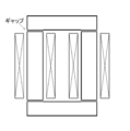
- a method is known in which a plurality of gaps are formed perpendicular to the magnetic path of the dust core and, for example, a resinous insulating material (nonmagnetic) is disposed in the gap (see, for example, References 1 to 3).
- the present invention has been made to solve the above-described problems, and its purpose is to uniformly disperse the periphery of soft magnetic powder with insulating fine powder and to form a magnetic core produced by high-pressure molding as a reactor.
- a dust core that maintains a high density and has a low permeability by using it as a magnetic core, the DC superposition characteristics of the reactor core can be improved. It is to provide a manufacturing method.
- the reactor of the present invention includes a soft magnetic powder and a soft magnetic powder obtained by mixing 0.4 to 1.5 wt% of an inorganic insulating powder with respect to the soft magnetic powder and performing heat treatment.
- the inorganic insulating powder is mixed with a binder insulating resin and granulated, and the mixture is mixed with a lubricating resin, and the mixture is pressure-molded to produce a molded body.
- a powder magnetic core is produced by annealing, a conductive wire is wound around the powder magnetic core, and a gap is not provided perpendicular to the magnetic path of the powder magnetic core serving as the core of the reactor.
- the powder magnetic core to be used and the reactor described below are also one embodiment of the present invention.
- (1) One prepared by mixing a soft magnetic powder and an inorganic insulating powder and then performing a heat treatment in a non-oxidizing atmosphere at a temperature of 1000 ° C. or higher and below the temperature at which the soft magnetic powder starts sintering.
- the inorganic insulating powder has an average particle size of 7 to 500 nm, or a soft component having a silicon component of 0.0 to 6.5 wt%. Using powder.
- the reactor of the present invention the following effects can be achieved by using a dust core excellent in DC superposition characteristics.
- the core of the reactor without the gap can prevent the winding and the core from generating heat due to the leakage magnetic flux in the vicinity of the gap, thereby preventing the circuit efficiency from being lowered.
- Noise to peripheral devices due to leakage magnetic flux in the vicinity of the gap can be prevented, and eddy current loss of peripheral conductors can be reduced.
- Since no gap is formed in the core, the assembly of the core is simple and inexpensive.
- Noise is generated by collision and separation of the gap and the magnetic body in each gap portion during driving. Further, the present invention can improve the direct current superposition characteristics of the powder magnetic core, so that the reactor can be downsized.
- the flowchart which shows the manufacturing method of the powder magnetic core of an Example The figure which showed the sum total of the half value width of each surface of (110), (200), (211) in the 1st characteristic comparison.
- the figure which showed the direct current BH characteristic of the dust core in the 2nd characteristic comparison The figure which showed the relation between differential permeability and magnetic flux density from the direct current BH characteristic in the second characteristic comparison.
- the figure which showed the direct current BH characteristic of the dust core in the 4th characteristic comparison The figure which showed the relation between differential permeability and magnetic flux density from direct current BH characteristic in the 4th characteristic comparison.
- the figure which shows the relationship between direct current superposition current and an inductance in the 4th characteristic comparison The figure which shows the relationship between direct current superposition current and an inductance in the 4th characteristic comparison.
- the figure which shows the relationship between direct current superposition current and an inductance in the 4th characteristic comparison The figure which shows the relationship between direct current superposition current and an inductance in the 4th characteristic comparison.
- the method for manufacturing a dust core according to the present invention having a reactor core includes the following steps as shown in FIG. (1) A first mixing step (step 1) in which an inorganic insulating powder is mixed with a soft magnetic powder. (2) A heat treatment step (step 2) in which heat treatment is performed on the mixture that has undergone the first mixing step. (3) A granulation step (step 3) in which a binder insulating resin is mixed with the soft magnetic powder and the inorganic insulating powder that have undergone the heat treatment step. (4) A second mixing step (step 4) in which a lubricating resin is mixed with the soft magnetic powder granulated with the binding insulating resin.
- step 5 A molding step in which the mixture that has undergone the second mixing step is pressure-molded to produce a molded body.
- An annealing process step 6) of annealing the molded body that has undergone the molding process.
- soft magnetic powder mainly composed of iron and inorganic insulating powder are mixed.
- a soft magnetic powder having an average particle diameter of 5 to 30 ⁇ m and a silicon component of 0.0 to 6.5 wt% prepared by a gas atomizing method, a water gas atomizing method and a water atomizing method is used.
- the average particle size is larger than the range of 5 to 30 ⁇ m, the eddy current loss (Pe) increases.
- the average particle size is smaller than the range of 5 to 30 ⁇ m, the hysteresis loss (Ph) due to density reduction increases.
- the silicon component of the soft magnetic powder is preferably 6.5 wt% or less with respect to the soft magnetic powder, and if it is more than this, the moldability is poor, and the density of the powder magnetic core is lowered and the magnetic properties are lowered. Will occur.
- the shape of the soft magnetic powder is indefinite, and the surface of the powder becomes uneven. For this reason, it is difficult to uniformly form the inorganic insulating powder on the surface of the soft magnetic powder. Furthermore, stress concentrates on the convex part of the powder surface during molding, and dielectric breakdown is likely to occur. Therefore, for mixing the soft magnetic powder and the inorganic insulating powder, an apparatus that develops mechanochemical effects in the powder, such as a V-type mixer, a W-type mixer, or a pot mill, is used. In addition, mixing and surface modification may be performed simultaneously by using a mixer of a type that gives mechanical energy such as compressive force and shear force to the particles.
- the mixed powder in which the inorganic insulating powder is mixed with the soft magnetic powder is subjected to a flattening process for uniformly dispersing the inorganic insulating powder on the surface and making the powder surface uneven.
- the direct current superimposition characteristic depends on the aspect ratio of the powder, and the aspect ratio may be set to 1.0 to 1.5 by this treatment.
- This method is performed by mechanically plastically deforming the surface. Examples include mechanical alloying, ball mills, and attritors.
- the average particle size of the inorganic insulating powder mixed here is 7 to 500 nm. If the average particle size is less than 7 nm, granulation is difficult, and if it exceeds 500 nm, it cannot be uniformly dispersed on the surface of the soft magnetic powder, and insulation cannot be maintained.
- the addition amount is preferably 0.4 to 1.5 wt%. When the content is less than 0.4 wt%, the performance cannot be sufficiently exhibited. When the content exceeds 1.5 wt%, the density is remarkably lowered, and thus the magnetic properties are lowered. Examples of such an inorganic insulating material, MgO (mp 2800 °) a melting point of 1500 ° C. greater, Al 2 O 3 (melting point 2046 °), TiO 2 (melting point 1640 °), among the CaO powder (melting point 2572 °) It is desirable to use at least one kind.
- an insulating powder such as talc or calcium carbonate can be used regardless of the melting point temperature.
- the temperature after the first mixing step is 1000 ° C. or higher and the temperature at which the soft magnetic powder starts sintering.
- Heat treatment is performed in the following non-oxidizing atmosphere.
- the non-oxidizing atmosphere may be a reducing atmosphere such as a hydrogen atmosphere, an inert atmosphere, or a vacuum atmosphere. That is, it is preferably not an oxidizing atmosphere.
- the inorganic insulating powder uniformly dispersed on the surface of the soft magnetic alloy powder in the first mixing step serves to prevent the soft magnetic powder from being fused with each other during the heat treatment.
- the domain wall can be obtained by removing strain existing in the soft magnetic powder, removing defects such as crystal grain boundaries, and growing (enlarging) crystal grains in the soft magnetic powder particles. The movement becomes easy, the coercive force can be reduced, and the hysteresis loss can be reduced.
- heat treatment is performed at a temperature at which the soft magnetic powder sinters, the soft magnetic powder sinters and hardens, which makes it impossible to use as a material for the dust core. Therefore, it is necessary to perform the heat treatment at a temperature below the temperature at which the soft magnetic powder starts sintering.
- This heat treatment step can be omitted depending on the type of inorganic insulating powder used.
- a uniform dispersion on the surface of the soft magnetic powder and a flattening process for making the unevenness of the powder surface uniform are performed. Therefore, the lower the hardness of the inorganic insulating powder, Therefore, hysteresis loss can be reduced.
- a double-structured insulating coating is formed for the purpose of uniformly dispersing the inorganic insulating powder and the purpose of improving adhesion.
- an adhesion strengthening layer is formed by a silane coupling agent on the surface of the soft magnetic alloy powder. This silane coupling agent is added to increase the adhesion between the inorganic insulating powder and the soft magnetic powder, and the optimum additive is 0.1 to 0.5 wt%. If the amount is less than this, the adhesion amount effect is insufficient, and if it is more than this, the molding density is lowered and the magnetic properties after annealing are deteriorated.
- a binder layer made of silicone resin is formed on the surface of the soft magnetic alloy powder on which an adhesion layer made of a silane coupling agent is formed.
- This silicone resin is added to improve the binding performance and to prevent the occurrence of vertical streaks on the core wall surface due to the contact between the mold and the powder during molding, and the amount added is 0.5 to 2.0 wt%. Is optimal. If the amount is less than this, the insulation performance is lowered, and vertical streaks to the core wall surface occur during molding. If the amount is too large, the molding density is lowered and the magnetic properties after annealing are deteriorated.
- Second mixing step In the second mixing step, the mixture having undergone the granulation step for the purpose of reducing the punching pressure of the upper punch at the time of molding and preventing the occurrence of vertical stripes on the core wall surface due to contact between the mold and the powder.
- Lubricating resin is mixed with
- waxes such as stearic acid, stearate, stearic acid soap, and ethylene bisstearamide can be used. By adding these, it is possible to improve the slippage between the granulated powders, so that the density during mixing can be improved and the molding density can be increased. Furthermore, it is possible to prevent the powder from being baked into the mold.
- the amount of the lubricating resin to be mixed is 0.2 to 0.8 wt% with respect to the soft magnetic powder. If it is less than this, a sufficient effect cannot be obtained, and vertical stripes are generated on the wall surface of the forming core, and the punching pressure increases, and in the worst case, the upper punch cannot be removed. If the amount is too large, the molding density is lowered and the magnetic properties after annealing are deteriorated.
- the soft magnetic powder bound by the binder as described above is put into a mold and uniaxially molded by a die floating method to form a molded body.
- the pressure-dried binding insulating resin acts as a binder during molding.
- the pressure at the time of molding may be the same as in the prior art, and is preferably about 1500 MPa in the present invention.
- the powder magnetic core is formed by performing an annealing process at a temperature exceeding 600 ° C. in N 2 gas or N 2 + H 2 gas non-oxidizing atmosphere. Produced. This is because if the annealing temperature is raised too much, the magnetic characteristics deteriorate due to the deterioration of the insulation performance, and in particular, the eddy current loss greatly increases, thereby suppressing the iron loss from increasing.
- the binding insulating resin is thermally decomposed when it reaches a certain temperature during the annealing process.
- the binding insulating resin adheres to the surface of the soft magnetic powder. Therefore, even if heat treatment is performed at a high temperature, the insulation does not deteriorate and hysteresis loss due to oxidation does not increase. It also serves to improve mechanical strength.
- Measurement item As measurement items, permeability, maximum magnetic flux density, and direct current superimposition are measured by the following method. The magnetic permeability was calculated from the inductance at 20 kHz and 0.5 V by applying a primary winding (20 turns) to the produced dust core and using an impedance analyzer (Agilent Technology: 4294A).
- the core loss is obtained by applying a primary winding (20 turns) and a secondary winding (3 turns) to the dust core, and using a BH analyzer (Iwatori Measurement Co., Ltd .: SY-8232) as a magnetic measurement instrument.
- the direct current superimposition property was measured by using an LCR meter for the produced reactor.
- Example 1 an Fe-Si alloy powder having an average particle diameter of 22 ⁇ m and having an average particle diameter of 22 ⁇ m prepared by gas atomization was added to an inorganic insulating powder as an average particle diameter of 13 nm (specific surface area of 100 m 2 / g) Add 0.4 wt% of Al 2 O 3 Thereafter, the samples of Examples 1 to 3 are reduced to 950 ° C. to 1150 ° C. in 25% hydrogen (the remaining 75% is nitrogen) in a reducing atmosphere for 2 hours. Holding and heat treatment were performed.
- Table 1 shows the half width evaluation of the peaks of each of (110), (200), and (211) in XRD for Examples 1 to 3 and Comparative Example 1
- FIG. FIG. 6 is a diagram showing the total half width of each surface of (110), (200), and (211) for Examples 1 to 3 and Comparative Example 1.
- the surface of the soft magnetic powder can be modified by heat-treating the soft magnetic powder at 1000 ° C. or higher.
- irregularities on the surface of the magnetic powder can be removed, and magnetic flux concentrates where the gap between the magnetic powders is small, preventing the magnetic flux density near the contact from increasing and hysteresis loss from increasing. Can do.
- the gap between the magnetic powders uniform, the gap provided between the magnetic powders becomes a dispersive gap, and the direct current superimposition characteristics can be improved.
- heat treatment is performed at a temperature at which the soft magnetic powder sinters, the soft magnetic powder sinters and hardens, which makes it impossible to use as a powder magnetic core material. Therefore, it is necessary to perform the heat treatment at a temperature below the temperature at which the soft magnetic powder starts sintering.
- the heat treatment temperature of the powder magnetic core used in the reactor is set to 1000 ° C. or higher and below the temperature at which the soft magnetic powder starts sintering. Accordingly, it is possible to provide a reactor and a reactor manufacturing method using a dust core that can effectively reduce hysteresis loss without being sintered and hardened during heat treatment of the soft magnetic powder.
- a sample used in this characteristic comparison was prepared by adding an inorganic insulating powder as described below to an Fe—Si alloy powder having an average particle diameter of 22 ⁇ m and a silicon component of 3.0 wt% prepared by a gas atomization method.
- Comparative Example 2 of Item A no inorganic insulating powder is added.
- Comparative Examples 3 and 4 of Item B 0.20 to 0.25 wt% of Al 2 O 3 having a thickness of 13 nm (specific surface area 100 m 2 / g) is added as the inorganic insulating powder.
- Al 2 O 3 having a thickness of 13 nm (specific surface area 100 m 2 / g) is added as an inorganic insulating powder in an amount of 0.40 to 1.50 wt%.
- Comparative Example 5 and Examples 11 to 13 of Item C 0.25 to 1.00 wt% of Al 2 O 3 with a thickness of 60 nm (specific surface area 25 m 2 / g) is added as the inorganic insulating powder.
- Comparative Example 6 and Example 14 of Item D 0.20 to 0.70 wt% of MgO having a thickness of 230 nm (specific surface area of 160 m 2 / g) is added as the inorganic insulating powder.
- Table 2 shows the relationship between soft magnetic powder, inorganic insulating powder type and addition amount, first heat treatment temperature, magnetic permeability, and iron loss per unit volume (core loss) for Examples 4 to 14 and Comparative Examples 2 to 6. It is the table
- FIG. 3 is a graph showing the relationship of DC superposition characteristics with respect to the amount of fine powder added in Examples 4 to 14 and Comparative Examples 2 to 6.
- 4 is a diagram showing the DC BH characteristics of Examples 4 and 7 and Comparative Example 2.
- FIG. 5 shows the relationship between the differential permeability and the magnetic flux density based on the DC BH characteristics of FIG. It is a thing.
- The% of the direct current BH characteristics in Table 2 is the ratio ( ⁇ (1T) / ⁇ (0T)) of the magnetic permeability ⁇ (0T) at the magnetic flux density 0T and the magnetic permeability ⁇ (1T) at the 1T.
- a large value means excellent DC superposition characteristics. That is, as can be seen from Table 2, in the soft magnetic powder produced by the gas atomization method with Si of 3.0 wt%, Comparative Examples 3 and 4 and Examples 4 to 10 in Item B, Comparative Example 5 and Example in Item C In Comparative Examples 6 and 14 of Items 11 to 13 and Item D, it is understood that the DC BH characteristics are improved by adding 0.4 wt% or more of fine powder in all items.
- the higher the density the smaller the hysteresis loss.
- the density is reduced, but the hysteresis loss (Ph) is reduced.
- the fine powder is uniformly dispersed to make the gap between the magnetic powders uniform, and the hysteresis loss due to the concentration of magnetic flux in the gap between the magnetic powders is reduced.
- a hysteresis loss (Ph) can be reduced.
- the gap provided between the magnetic powders becomes a dispersive gap, and the direct current superimposition characteristics can be improved.
- the amount of the inorganic insulating material added to the soft magnetic powder of the Fe-Si alloy powder of 3.0 wt% silicon component of the powder magnetic core used for the reactor is 0.4% with respect to the soft magnetic powder. It is good that it is ⁇ 1.5 wt%. If it is less than this, a sufficient effect cannot be obtained, and if it exceeds 1.5 wt%, it becomes a factor of direct current BH characteristics due to density reduction. Accordingly, there is provided a reactor and a reactor manufacturing method using a dust core that can effectively reduce hysteresis loss without sintering and hardening even during soft magnetic powder having a silicon component of 3.0 wt%. Can be provided.
- the sample used in this characteristic comparison was prepared by adding an inorganic insulating powder to a Fe-Si alloy powder having an average particle size of 22 ⁇ m and having an average particle diameter of 22 ⁇ m and having an average particle diameter of 22 ⁇ m as described below. And was mixed for 30 minutes.
- Comparative Example 7 of Item E no inorganic insulating powder is added.
- Comparative Examples 8 and 9 of Item F 0.15 to 0.25 wt% of Al 2 O 3 having a thickness of 13 nm (specific surface area 100 m 2 / g) is added as the inorganic insulating powder.
- 0.42 to 1.00 wt% of Al 2 O 3 having a thickness of 13 nm (specific surface area 100 m 2 / g) is added as the inorganic insulating powder.
- Table 3 shows the relationship between soft magnetic powder, inorganic insulating powder type and addition amount, first heat treatment temperature, magnetic permeability, and iron loss per unit volume (core loss) for Examples 15 to 18 and Comparative Examples 7 to 9. It is the table
- FIG. 6 is a graph showing the relationship of DC superposition characteristics with respect to the amount of fine powder added in Examples 15 to 18 and Comparative Examples 8 and 9.
- The% of DC BH characteristics in Table 3 is the ratio ( ⁇ (1T) / ⁇ (0T)) of magnetic permeability ⁇ (0T) at magnetic flux density 0T and magnetic permeability ⁇ (1T) at 1T.
- a large value means excellent DC superposition characteristics. That is, as can be seen from Table 3 and FIG. 6, in the soft magnetic powders produced by the gas atomization method with Si of 6.5 wt%, the fine powders of 0. 9 and Comparative Examples 8 and 9 and Examples 15 to 18 were reduced to 0. It can be seen that the DC BH characteristics are improved by adding 4 wt% or more.
- the higher the density the smaller the hysteresis loss.
- the density is reduced, but the hysteresis loss (Ph) is reduced.
- the fine powder is uniformly dispersed to make the gap between the magnetic powders uniform, and the hysteresis loss due to the concentration of magnetic flux in the gap between the magnetic powders is reduced.
- a hysteresis loss (Ph) can be reduced.
- the gap provided between the magnetic powders becomes a dispersive gap, and the direct current superimposition characteristics can be improved.
- the amount of the inorganic insulating material added to the soft magnetic powder of the Fe-Si alloy powder of 6.5 wt% silicon component of the dust core used for the reactor is 0.4% with respect to the soft magnetic powder. It is good that it is ⁇ 1.5 wt%. If it is less than this, a sufficient effect cannot be obtained, and if it exceeds 1.5 wt%, it becomes a factor of direct current BH characteristics due to density reduction. Accordingly, there is provided a reactor and a reactor manufacturing method using a dust core that can effectively reduce hysteresis loss without sintering and hardening even during soft magnetic powder having a silicon component of 6.5 wt%. Can be provided.
- Example 19 of Item G 13 nm of Al 2 O 3 (specific surface area 100 m 2 / g) was added as an inorganic insulating material to pure iron having a particle size of 75 ⁇ m or less prepared by a water atomization method, and a V-type mixer was used. And mix for 30 minutes.
- Example 20 of Item H pure iron with a particle size of 75 ⁇ m or less produced by the water atomization method is flattened, and pure iron with a circularity of 0.85 is mixed with 13 nm (ratio of Al 2 O 3 as an inorganic insulating substance).
- Example 21 of Item I 13 nm of Al 2 O 3 (specific surface area of 100 m 2 / g) was added as an inorganic insulating material to Fe—Si alloy powder having a particle size of 63 ⁇ m or less and having a particle size of 63 ⁇ m or less prepared by water atomization. And mix for 30 minutes using a V-type mixer.
- Table 4 is a table showing the relationship between the types and addition amounts of the soft magnetic powder and the inorganic insulating powder, the first heat treatment temperature, the magnetic permeability, and the iron loss (core loss) per unit volume for Examples 19 to 21.
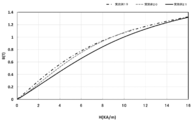
- FIG. 7 is a diagram showing the DC BH characteristics of Examples 19 to 21, and FIG. 8 shows the relationship between the differential magnetic permeability and the magnetic flux density based on the DC BH characteristics of FIG.
- The% of the direct current BH characteristics in Table 4 is the ratio ( ⁇ (1T) / ⁇ (0T)) of the magnetic permeability ⁇ (0T) at a magnetic flux density of 0T and the magnetic permeability ⁇ (1T) at 1T.
- a large value means excellent DC superposition characteristics. That is, as can be seen from Table 4, also in Examples 19 and 20 in which the Si component is 0 and Example 21 in which the Si component is 1.0 wt%, the gas atomization method with Si of 3.0 to 6.5 wt% is used. It can be seen that the direct current BH characteristics are improved by adding the inorganic insulating powder in the same manner as the produced soft magnetic powder. Further, comparing Examples 20 and 21 of FIG. 8, it can be seen that those subjected to the flattening process are excellent in DC superposition characteristics.
- the example 20 in which the flattening process is performed is superior to the example 19 in which the flattening process is not performed on the soft magnetic powder, and the relative permeability in the applied magnetic field is superior.
- the dust core has a characteristic that the DC superposition characteristic is excellent when the density is high, and the DC superposition characteristic is improved by increasing the density of the dust core.
- the soft magnetic alloy powder of the powder magnetic core used for the reactor is a low loss powder magnetic core by using soft magnetic powder of Fe-Si alloy powder with a silicon component of 0 to 6.5 wt%.
- by performing the flattening process together it is possible to provide a reactor and a reactor manufacturing method using a dust core having a higher density and excellent DC superposition characteristics.
- a sample used in this characteristic comparison was prepared by adding an inorganic insulating powder as described below to an Fe—Si alloy powder having an average particle diameter of 22 ⁇ m and a silicon component of 3.0 wt% prepared by a gas atomization method.
- an inorganic insulating powder as described below to an Fe—Si alloy powder having an average particle diameter of 22 ⁇ m and a silicon component of 3.0 wt% prepared by a gas atomization method.
- 0.25 to 1.00 wt% of Al 2 O 3 having a thickness of 13 nm (specific surface area 100 m 2 / g) is added as an inorganic insulating powder.
- Samples of items J, K, and M were pressure-molded at a pressure of 1500 MPa at room temperature, and samples of item L were pressure-molded at a pressure of 1200 MPa at room temperature. Thereafter, a dust core having a ring shape with an outer diameter of 60 mm, an inner diameter of 30 mm, and a height of 25 mm was produced. And these powder magnetic cores were annealed at 625 ° C. for 30 minutes in a nitrogen atmosphere (N 2 + H 2 ). For these samples, a copper wire having a wire diameter of 2.2 mm was wound (turned) for 60 turns, and a reactor was prepared. The direct current superposition characteristics were measured with an LCR meter.
- Table 5 is a table showing the relationship between the added amount of the inorganic insulating powder, the density, the density of the magnetic part, and the magnetic permeability for Examples 22 to 24 and Comparative Examples 10 to 12. From Table 2, it can be seen that the density, the density of the magnetic portion, and the magnetic permeability decrease as the amount of the inorganic insulating powder added is increased.
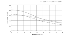
- FIG. 9 is a diagram showing the relationship between the DC superimposed current and the inductance for Example 22 and Comparative Example 10. Compared to Example 22, Comparative Example 10 in FIG. 9 shows that the inductance of Comparative Example 10 is larger at 12 A or less, but the inductance of Comparative Example 10 is reduced when the current exceeds 12 A. That is, it can be seen that the reduction rate of the inductance is larger in Comparative Example 10 and the reactor is more affected by the inductance.
- FIG. 10 is a diagram showing the relationship between the DC superimposed current and the inductance in each example and comparative example for Example 22 and Comparative Examples 11 and 12. From FIG. 10, comparing Example 22 and Comparative Example 12, it can be seen that Comparative Example 12 having a gap in the reactor has a lower inductance reduction rate at 25 A or more. That is, it can be seen that excellent superposition characteristics can be obtained by providing a gap in the reactor even if the amount of inorganic insulating powder added is small.
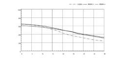
- FIG. 11 is a diagram showing the relationship between the DC superimposed current and the inductance in each of Examples and Comparative Examples for Examples 23 and 24 and Comparative Example 11. From FIG. 11, when Examples 23 and 24 are compared with Comparative Example 12, even in Examples 23 and 24 in which no gap is provided in the reactor, the DC superimposition characteristics are the same as in Comparative Example 12 in which a gap is provided in the reactor. I understand that. *
- FIG. 12 is a diagram showing the relationship between the superimposed DC current and the inductance in Examples and Comparative Examples for Examples 23 and 24 and Comparative Example 12.
- Comparative Example 12 the density was reduced by lowering the pressure during molding, and the L value was adjusted to that of Examples 23 and 24. However, it can be seen that the L value greatly decreases at 10 A or more. That is, it can be seen that the direct current superposition characteristics can be improved by adding insulating powder and molding at a predetermined pressure as in Examples 23 and 24. *
- the soft magnetic powder of the powder magnetic core used for the reactor and the inorganic insulating powder of 0.4 wt% to 1.5 wt% are mixed, and the first heat treatment temperature is 1000 ° C or higher and the soft magnetic powder starts sintering.
- a reactor using a dust core produced by heat treatment in a non-oxidizing atmosphere at a temperature lower than the temperature to be used as a reactor core a reactor with excellent DC superposition characteristics that does not significantly reduce the L value (inductance) at a high magnetic field And the manufacturing method can be provided.
Landscapes
- Engineering & Computer Science (AREA)
- Power Engineering (AREA)
- Chemical & Material Sciences (AREA)
- Dispersion Chemistry (AREA)
- Manufacturing & Machinery (AREA)
- Spectroscopy & Molecular Physics (AREA)
- Physics & Mathematics (AREA)
- Materials Engineering (AREA)
- Mechanical Engineering (AREA)
- Metallurgy (AREA)
- Organic Chemistry (AREA)
- Soft Magnetic Materials (AREA)
- Powder Metallurgy (AREA)
Abstract
Description
[式1]Pc=Ph+Pe・・・(1)
[式2]Ph=Kh×f Pe=Ke×f2・・・(2)
Kh:ヒステリシス損係数 Ke=渦電流損係数 f=周波数
[式3]Ke=k1Bm2t2/ρ・・・(3)
k1:係数、Bm:磁束密度、t:粒子径(板材の場合厚さ)、ρ:比抵抗
(1)軟磁性粉末と無機絶縁粉末とを混合した後に、1000℃以上且つ軟磁性粉末が焼結を開始する温度以下での非酸化性雰囲気で熱処理を行うことにより作製したもの。
(2)軟磁性粉末の表面に均一に分散し、絶縁性を保持するために、無機絶縁粉末の平均粒子径が7~500nmとしたり、珪素成分が0.0~6.5wt%の軟磁性粉末を使用したもの。
(3)珪素成分が0~6.5%の前記軟磁性合金粉末を使用したもの。
(1)ギャップのないリアクトルのコアにより、ギャップ付近の漏れ磁束による巻き線及びコアの発熱を防止し、回路効率が低下を防止することできる。
(2)ギャップ付近の漏れ磁束による周辺機器に対するノイズを防止し、周辺の導体の渦電流損失を低減できる。
(3)コアにギャップを形成しないので、コアの組み立てが簡易であり、安価である。
(4)駆動時に各ギャップ部において、ギャップと磁性体が衝突、離反することで騒音が発生する。さらに、本発明は圧粉磁心の直流重畳特性を改善できるため、リアクトルの小型化が可能となる。
本発明のリアクトルコアとする圧粉磁心の製造方法は、図1に示すような次のような各工程を有する。
(1)軟磁性粉末に無機絶縁粉末を混合する第1混合工程(ステップ1)。
(2)第1混合工程を経た混合物に対して熱処理を施す熱処理工程(ステップ2)。
(3)熱処理工程を経た軟磁性粉末と無機絶縁粉末とに結着性絶縁樹脂を混合する造粒工程(ステップ3)。
(4)結着性絶縁樹脂で造粒した軟磁性粉末に対して、潤滑性樹脂を混合する第2混合工程(ステップ4)。
(5)第2混合工程を経た混合物を、加圧成形処理して成形体を作製する成形工程(ステップ5)。
(6)成形工程を経た成形体を焼鈍処理する焼鈍工程(ステップ6)。
以下、各工程を具体的に説明する。
第1混合工程では、鉄を主とする軟磁性粉末と無機絶縁粉末とを混合する。
[軟磁性粉末について]
軟磁性粉末は、ガスアトマイズ法、水ガスアトマイズ法及び水アトマイズ法で作製した平均粒径が5~30μmで、珪素成分が0.0~6.5wt%の軟磁性粉末を使用する。平均粒径が、5~30μmの範囲より大きいと渦電流損失(Pe)が増大し、一方、平均粒径が5~30μmの範囲より小さいと、密度低下によるヒステリシス損失(Ph)が増加する。また、軟磁性粉末の珪素成分は、前記軟磁性粉末に対して6.5wt%以下が良く、これより多いと成形性が悪く、圧粉磁心の密度が低下して磁気特性が低下するという問題が発生する。
ここで混合する無機絶縁粉末の平均粒径は、7~500nmとする。平均粒径が7nm未満であると、造粒が困難であり、500nm超であると、軟磁性粉末の表面に均一に分散することができず、絶縁性を保持することができない。また、添加量としては、0.4~1.5wt%が好適である。0.4wt%未満であると、性能が充分に発揮できず、1.5wt%を超えると、密度が著しく低下するために、磁気特性を低下させる。このような無機絶縁物質としては、融点が1500℃超であるMgO(融点2800度)、Al2O3(融点2046度)、TiO2(融点1640度)、CaO粉末(融点2572度)のうち少なくとも1種類以上を使用することが望ましい。
熱処理工程では、ヒステリシス損失を低減する目的と成形後の焼鈍温度を高くする目的で、前記第1混合工程を経た混合物を1000℃以上且つ軟磁性粉末が焼結を開始する温度以下の非酸化性雰囲気中で熱処理を行う。非酸化性雰囲気は、水素雰囲気等の還元雰囲気でも、不活性雰囲気でも、真空雰囲気でもよい。つまり、酸化雰囲気でないことが好ましい。
造粒工程では、前記無機絶縁粉末を均一に分散させる目的と密着性を向上させる目的のために、2重構造の絶縁被膜を構成する。第1層目として、軟磁性合金粉末の表面にシランカップリング剤による密着強化層を形成する。このシランカップリング剤は無機絶縁粉末と軟磁性粉末の密着力を高めるために添加し、添加料は、0.1~0.5wt%が最適である。これより量が少ないと密着量効果が不十分であり、多いと成形密度の低下を引き起こし焼鈍後の磁気特性を劣化させる。第2層目としては、シランカップリング剤による密着層を形成した軟磁性合金粉末の表面に、シリコーンレジンによる結着層を形成する。このシリコーンレジンは、結着性能を向上させるとともに、成形時、金型と粉末の接触によるコア壁面の縦筋の発生を防止するために添加し、添加量は0.5~2.0wt%が最適である。これより量が少ないと絶縁性能の低下、成形時コア壁面への縦筋が発生する。多いと成形密度の低下を引き起こし焼鈍後の磁気特性を劣化させる。
第2混合工程では、成形時の上パンチの抜き圧低減、金型と粉末の接触によるコア壁面の縦筋の発生を防止する目的で、前記造粒工程を経た混合物に潤滑性樹脂を混合する。ここで混合する潤滑性樹脂としては、ステアリン酸、ステアリン酸塩、ステアリン酸石鹸、エチレンビスステアラマイドなどのワックスが使用できる。これらを添加することにより、造粒粉同士の滑りを良くすることができるので、混合時の密度を向上することができ成形密度を高くすることができる。さらに、粉末が金型へ焼き付くことも防止することが可能である。混合する潤滑性樹脂の量は、前記軟磁性粉末に対して0.2~0.8wt%とする。これよりも少なければ、十分な効果を得ることができず、形時コア壁面への縦筋の発生、抜き圧が高くなり最悪の場合、上パンチが抜けなくなる。多いと成形密度の低下を引き起こし焼鈍後の磁気特性を劣化させる。
成形工程では、前記のようにして結着剤により結着した軟磁性粉末を金型に投入しダイ・フローティング法による1軸成形を行なうことにより、成形体を形成する。この時、加圧乾燥された結着性絶縁樹脂は、成形時のバインダーとして作用する。成形時の圧力は従来技術と同様で良く、本発明においては1500MPa程度が好ましい。
焼鈍工程では、前記成形体に対して、N2ガス中やN2+H2ガス非酸化性雰囲気中にて、600℃を超える温度で焼鈍処理を行うことで圧粉磁心が作製される。焼鈍温度を上げ過ぎると絶縁性能の劣化から磁気特性が劣化するため、特に渦電流損失が大きく増加してしまうことにより、鉄損が増加するのを抑制するためである。
測定項目として、透磁率と最大磁束密度と直流重畳性を次のような手法により測定する。透磁率は、作製された圧粉磁心に1次巻線(20ターン)を施し、インピーダンスアナライザー(アジレントテクノロジー:4294A)を使用することで、20kHz、0.5Vにおけるインダクタンスから算出した。
Pc=Kh×f+Ke×f2
Ph=Kh×f
Pe=Ke×f2
Pc:鉄損
Kh:ヒステリシス損係数
Ke:渦電流損係数
f:周波数
Ph:ヒステリシス損失
Pe:渦電流損失
第1の特性比較では、熱処理工程の熱処理による軟磁性粉末の表面の改質の比較を行った。表1では、実施例1~3及び比較例1として熱処理工程において粉末に加える温度の比較を行った。表1は、軟磁性粉末に加えた温度と軟磁性粉末をX線回折法(以下、XRDとする)における評価を示した表である。

第2の特性比較では、珪素成分3.0wt%のFe-Si合金粉末に添加する無機絶縁物質の添加量の比較を行った。表2は、比較例2~6及び実施例4~14として軟磁性粉末に添加した無機絶縁物質の種類と成分を示した表である。各無機絶縁物質の平均粒径は、Al2O3が13nm(比表面積100m2/g)及び60nm,(比表面積25m2/g),MgOが230nm(比表面積160m2/g)である。
項目Aの比較例2では、無機絶縁粉末を添加しない。
項目Bの比較例3、4では、無機絶縁粉末として、13nm(比表面積100m2/g)のAl2O3を0.20~0.25wt%添加する。
また、実施例4~10では、無機絶縁粉末として、13nm(比表面積100m2/g)のAl2O3を0.40~1.50wt%添加する。
項目Dの比較例6及び実施例14では、無機絶縁粉末として、230nm(比表面積160m2/g)のMgOを0.20~0.70wt%添加する。

表2の直流BH特性の%とは、磁束密度が0Tでの透磁率μ(0T)と1Tでの透磁率μ(1T)の比(μ(1T)/μ(0T))である、この値が大きいと直流重畳特性が優れている意味である。すなわち、表2から判るように、Siが3.0wt%のガスアトマイズ法で作製した軟磁性粉末では、項目Bの比較例3,4と実施例4~10、項目Cの比較例5と実施例11~13、項目Dの比較例6と実施例14では、すべての項目において、微粉末を0.4wt%以上添加することにより直流BH特性が良くなることが判る。
表2のヒステリシス損失(Ph)では、無機絶縁体としてAl2O3を添加した実施例4~14及び比較3~6の場合、無機絶縁粉末を添加していない比較例1よりも、10kHzにおけるヒステリシス損失(Ph)が低下している。それにより、全体での磁気特性が向上していることが判る。
第3の特性比較では、軟磁性の粉末として、珪素成分6.5wt%のFe-Si合金粉末に添加する無機絶縁物質の添加量の比較を行った。表3は、比較例7~9及び実施例15~18として軟磁性粉末に添加した無機絶縁物質の種類と成分を示した表である。無機絶縁物質の平均粒径は、Al2O3が13nm(比表面積100m2/g)である。
項目Eの比較例7では、無機絶縁粉末を添加しない。
項目Fの比較例8,9では、無機絶縁粉末として、13nm(比表面積100m2/g)のAl2O3を0.15~0.25wt%添加する。
また、実施例15~18では、無機絶縁粉末として、13nm(比表面積100m2/g)のAl2O3を0.40~1.00wt%添加する。

表3の直流BH特性の%とは、磁束密度が0Tでの透磁率μ(0T)と1Tでの透磁率μ(1T)の比(μ(1T)/μ(0T))である、この値が大きいと直流重畳特性が優れている意味である。すなわち、表3及び図6から判るように、Siが6.5wt%のガスアトマイズ法で作製した軟磁性粉末では、項目Fの比較例8,9と実施例15~18では、微粉末を0.4wt%以上添加することにより直流BH特性が良くなることが判る。
表3のヒステリシス損失(Ph)では、無機絶縁体としてAl2O3を添加した実施例15~18及び比較例8,9の場合、無機絶縁粉末を添加していない比較例7よりも、10kHzにおけるヒステリシス損失(Ph)が低下している。それにより、全体での磁気特性が向上していることが判る。
第3の特性比較では、無機絶縁粉末を添加する軟磁性粉末の種類の比較を行った。本特性比較で使用する軟磁性粉末は、水アトマイズ法で作製した粒度75μm以下の純鉄、水アトマイズ法で作製した粒度75μm以下の純鉄を平坦化処理し、円形度を0.85とした純鉄及び、水アトマイズ法で作製した粒度63μm以下の珪素成分1wt%のFe-Si合金粉末である。
項目Gの実施例19では、水アトマイズ法で作製した粒度75μm以下の純鉄に、無機絶縁物質としてAl2O3が13nm(比表面積100m2/g)を添加し、V型混合機を使用し30分混合する。
項目Hの実施例20では、水アトマイズ法で作製した粒度75μm以下の純鉄を平坦化処理し、円形度を0.85とした純鉄に、無機絶縁物質としてAl2O3が13nm(比表面積100m2/g)を添加し、V型混合機を使用し30分混合する。
項目Iの実施例21では、水アトマイズ法で作製した粒度63μm以下の珪素成分1wt%のFe-Si合金粉末に、無機絶縁物質としてAl2O3が13nm(比表面積100m2/g)を添加し、V型混合機を使用し30分混合する。

表4の直流BH特性の%とは、磁束密度が0Tでの透磁率μ(0T)と1Tでの透磁率μ(1T)の比(μ(1T)/μ(0T))である、この値が大きいと直流重畳特性が優れている意味である。すなわち、表4から判るように、Si成分が0である実施例19,20及びSi成分が1.0wt%である実施例21においても、Siが3.0~6.5wt%のガスアトマイズ法で作製した軟磁性粉末と同様に、無機絶縁粉末を添加することにより、直流BH特性が良くなることが判る。また、図8の実施例20,21とを比較すると、平坦化処理を行ったものは、直流重畳特性が優れることがわかる。
第3の特性比較では、軟磁性粉末に添加する無機絶縁物質の添加量を変化させたリアクトル磁心の比較を行った。表5は、比較例10~12及び実施例22~24として軟磁性粉末に添加した無機絶縁物質の添加量を示した表である。無機絶縁物質の平均粒径は、Al2O3が13nm(比表面積100m2/g)である。
項目J~Mの比較例10~12及び実施例22~24は、無機絶縁粉末として、13nm(比表面積100m2/g)のAl2O3を0.25~1.00wt%添加する。

Claims (8)
- 軟磁性粉末と軟磁性粉末に対して0.4wt%~1.5wt%の無機絶縁粉末を混合し、
その混合物と結着性絶縁樹脂を混合して造粒し、その混合物に対して潤滑性樹脂を混合し、
その混合物を加圧成形処理して成形体を作製し、その成形体を焼鈍処理することにより作製した圧粉磁心に導線を巻回したリアクトルにおいて、
リアクトルのコアとなる圧粉磁心の磁路に直交してギャップを設けないことを特徴とするリアクトル。 - 前記軟磁性粉末と前記無機絶縁粉末とを混合した後、その混合物に対して1000℃以上且つ軟磁性粉末が焼結を開始する温度以下での非酸化性雰囲気で熱処理を行うことにより作製した圧粉磁心に導線を巻回したことを特徴とする請求項1に記載のリアクトル。
- 前記無機絶縁粉末の平均粒子径が7~500nmであることを特徴とする請求項1または2に記載のリアクトル。
- 前記軟磁性粉末の珪素成分が0~6.5wt%であることを特徴とする請求項1~3のいずれか1項に記載のリアクトル。
- 軟磁性粉末と前記軟磁性粉末に対して0.4wt%~1.5wt%の無機絶縁粉末とを混合する第1混合工程と、
前記第1混合工程を経た軟磁性粉末と無機絶縁粉末に結着性絶縁樹脂を混合して結着する結着工程と、
前記結着工程を経た混合物に対して、潤滑性樹脂を混合する第2混合工程と、
前記第2混合工程を経た混合物を、加圧成形処理して成形体を作製する成形工程と、
前記成形工程を経た成形体を焼鈍処理し圧粉磁心を作製する焼鈍工程と、
前記焼鈍工程を経た圧粉磁心に導線を巻回する実装工程とを備えるリアクトルの製造方法において、
リアクトルのコアとなる圧粉磁心の磁路に直交してギャップを設けないことを特徴とするリアクトルの製造方法。 - 前記軟磁性粉末と前記無機絶縁粉末とを混合する第1混合工程の後、その混合物に対して1000℃以上且つ軟磁性粉末が焼結を開始する温度以下での非酸化性雰囲気で熱処理を行う熱処理工程を備えることを特徴とする請求項5に記載のリアクトルの製造方法。
- 前記無機絶縁粉末の平均粒子径が7~500nmであることを特徴とする請求項5または6に記載のリアクトルの製造方法。
- 前記軟磁性粉末の珪素成分が0~6.5wt%であることを特徴とする請求項5~7のいずれか1項に記載のリアクトルの製造方法。
Priority Applications (5)
| Application Number | Priority Date | Filing Date | Title |
|---|---|---|---|
| KR1020127019388A KR101527268B1 (ko) | 2009-12-25 | 2010-12-20 | 리액터 및 그의 제조 방법 |
| EP10838933.9A EP2518740B1 (en) | 2009-12-25 | 2010-12-20 | Method for producing a reactor |
| CN201080058746.8A CN102667977B (zh) | 2009-12-25 | 2010-12-20 | 电抗器和电抗器的制造方法 |
| US13/519,101 US8810353B2 (en) | 2009-12-25 | 2010-12-20 | Reactor and method for manufacturing same |
| JP2011547295A JP5739348B2 (ja) | 2009-12-25 | 2010-12-20 | リアクトル及びその製造方法 |
Applications Claiming Priority (2)
| Application Number | Priority Date | Filing Date | Title |
|---|---|---|---|
| JP2009296417 | 2009-12-25 | ||
| JP2009-296417 | 2009-12-25 |
Publications (1)
| Publication Number | Publication Date |
|---|---|
| WO2011077694A1 true WO2011077694A1 (ja) | 2011-06-30 |
Family
ID=44195248
Family Applications (1)
| Application Number | Title | Priority Date | Filing Date |
|---|---|---|---|
| PCT/JP2010/007369 WO2011077694A1 (ja) | 2009-12-25 | 2010-12-20 | リアクトル及びその製造方法 |
Country Status (6)
| Country | Link |
|---|---|
| US (1) | US8810353B2 (ja) |
| EP (2) | EP3252786A1 (ja) |
| JP (1) | JP5739348B2 (ja) |
| KR (1) | KR101527268B1 (ja) |
| CN (1) | CN102667977B (ja) |
| WO (1) | WO2011077694A1 (ja) |
Cited By (4)
| Publication number | Priority date | Publication date | Assignee | Title |
|---|---|---|---|---|
| CN102658367A (zh) * | 2012-05-16 | 2012-09-12 | 上海大学 | 稳恒磁场下粉末烧结法制备高硅硅钢片的方法及其装置 |
| JP2014072478A (ja) * | 2012-10-01 | 2014-04-21 | Panasonic Corp | 圧粉磁心の製造方法とその製造方法で作製された圧粉磁心を用いた磁性素子の製造方法 |
| JP2015095570A (ja) * | 2013-11-12 | 2015-05-18 | 株式会社タムラ製作所 | 低騒音リアクトル、圧粉磁心およびその製造方法 |
| KR20220158841A (ko) | 2020-06-15 | 2022-12-01 | 가부시키가이샤 고베 세이코쇼 | 압분자심용 분말 |
Families Citing this family (13)
| Publication number | Priority date | Publication date | Assignee | Title |
|---|---|---|---|---|
| EP2492031B1 (en) * | 2009-12-25 | 2017-10-18 | Tamura Corporation | Dust core and process for producing same |
| US10840005B2 (en) | 2013-01-25 | 2020-11-17 | Vishay Dale Electronics, Llc | Low profile high current composite transformer |
| EP2811495B1 (en) * | 2013-06-05 | 2017-01-11 | Delphi Automotive Systems Luxembourg SA | Transformer |
| CN105268975B (zh) * | 2014-07-11 | 2017-08-29 | 台耀科技股份有限公司 | 高密度粉末冶金金属软磁材料的制备方法 |
| WO2016039267A1 (ja) | 2014-09-08 | 2016-03-17 | トヨタ自動車株式会社 | 圧粉磁心、磁心用粉末およびそれらの製造方法 |
| CN105149581B (zh) * | 2015-09-16 | 2017-10-31 | 江苏佰迪凯磁性材料有限公司 | 避免es磁芯烧结过程中变形开裂的方法 |
| CN108028131B (zh) * | 2015-09-16 | 2021-11-12 | 日立金属株式会社 | 压粉磁芯的制造方法 |
| JP6378156B2 (ja) * | 2015-10-14 | 2018-08-22 | トヨタ自動車株式会社 | 圧粉磁心、圧粉磁心用粉末、および圧粉磁心の製造方法 |
| US10998124B2 (en) | 2016-05-06 | 2021-05-04 | Vishay Dale Electronics, Llc | Nested flat wound coils forming windings for transformers and inductors |
| CN105993053B (zh) * | 2016-05-13 | 2018-02-02 | 深圳顺络电子股份有限公司 | 复合软磁材料及其制备方法 |
| EP3507816A4 (en) | 2016-08-31 | 2020-02-26 | Vishay Dale Electronics, LLC | INDUCTANCE COIL COMPRISING A HIGH CURRENT COIL HAVING LOW DIRECT CURRENT RESISTANCE |
| JP6858158B2 (ja) * | 2018-06-13 | 2021-04-14 | 株式会社タムラ製作所 | コア、リアクトル、コアの製造方法及びリアクトルの製造方法 |
| US11948724B2 (en) | 2021-06-18 | 2024-04-02 | Vishay Dale Electronics, Llc | Method for making a multi-thickness electro-magnetic device |
Citations (15)
| Publication number | Priority date | Publication date | Assignee | Title |
|---|---|---|---|---|
| JP2002033211A (ja) * | 2000-07-17 | 2002-01-31 | Tokin Corp | 圧粉磁芯及びその製造方法 |
| JP2003217919A (ja) * | 2002-01-17 | 2003-07-31 | Nec Tokin Corp | 圧粉磁芯及びこれを用いた高周波リアクトル |
| JP2003332116A (ja) * | 2002-05-15 | 2003-11-21 | Hitachi Powdered Metals Co Ltd | 圧粉磁心およびその製造方法 |
| JP2004095935A (ja) | 2002-09-02 | 2004-03-25 | Jfe Steel Kk | 分割鉄心 |
| JP2005217289A (ja) * | 2004-01-30 | 2005-08-11 | Sumitomo Electric Ind Ltd | 圧粉磁心およびその製造方法 |
| JP2005336513A (ja) * | 2004-05-24 | 2005-12-08 | Sumitomo Electric Ind Ltd | 軟磁性材料の製造方法、軟磁性材料、圧粉磁心の製造方法、および圧粉磁心 |
| JP2006344867A (ja) | 2005-06-10 | 2006-12-21 | Sumitomo Electric Ind Ltd | リアクトル |
| JP2006344868A (ja) | 2005-06-10 | 2006-12-21 | Sumitomo Electric Ind Ltd | リアクトル及びトランス |
| JP2007012866A (ja) | 2005-06-30 | 2007-01-18 | Daido Steel Co Ltd | リアクトル用圧粉磁心 |
| JP2007214366A (ja) * | 2006-02-09 | 2007-08-23 | Toyota Motor Corp | 圧粉磁心用粉末、圧粉磁心およびそれらの製造方法 |
| JP2008112935A (ja) * | 2006-10-31 | 2008-05-15 | Sumitomo Electric Ind Ltd | リアクトル |
| JP2009224584A (ja) | 2008-03-17 | 2009-10-01 | Toyota Motor Corp | リアクトル装置 |
| JP2009302165A (ja) * | 2008-06-11 | 2009-12-24 | Tamura Seisakusho Co Ltd | 圧粉磁心及びその製造方法 |
| JP2010245459A (ja) * | 2009-04-09 | 2010-10-28 | Tamura Seisakusho Co Ltd | 圧粉磁心及びその製造方法 |
| JP2010251474A (ja) * | 2009-04-14 | 2010-11-04 | Tamura Seisakusho Co Ltd | 圧粉磁心及びその製造方法 |
Family Cites Families (9)
| Publication number | Priority date | Publication date | Assignee | Title |
|---|---|---|---|---|
| JPH0837107A (ja) * | 1994-07-22 | 1996-02-06 | Tdk Corp | 圧粉コア |
| US6284060B1 (en) | 1997-04-18 | 2001-09-04 | Matsushita Electric Industrial Co., Ltd. | Magnetic core and method of manufacturing the same |
| TW428183B (en) | 1997-04-18 | 2001-04-01 | Matsushita Electric Ind Co Ltd | Magnetic core and method of manufacturing the same |
| JP4596697B2 (ja) | 2001-07-19 | 2010-12-08 | ローム株式会社 | 積分型a/dコンバータ |
| US6964811B2 (en) * | 2002-09-20 | 2005-11-15 | Hitachi Maxell, Ltd. | Magnetic powder, method for producing the same and magnetic recording medium comprising the same |
| CA2452234A1 (en) * | 2002-12-26 | 2004-06-26 | Jfe Steel Corporation | Metal powder and powder magnetic core using the same |
| US8048191B2 (en) * | 2005-12-28 | 2011-11-01 | Advanced Technology & Material Co., Ltd. | Compound magnetic powder and magnetic powder cores, and methods for making them thereof |
| WO2010082486A1 (ja) * | 2009-01-16 | 2010-07-22 | パナソニック株式会社 | 複合磁性材料の製造方法とそれを用いた圧粉磁芯及びその製造方法 |
| CN102341869A (zh) * | 2009-03-09 | 2012-02-01 | 松下电器产业株式会社 | 压粉磁芯及使用该压粉磁芯的磁性元件 |
-
2010
- 2010-12-20 CN CN201080058746.8A patent/CN102667977B/zh active Active
- 2010-12-20 JP JP2011547295A patent/JP5739348B2/ja active Active
- 2010-12-20 US US13/519,101 patent/US8810353B2/en active Active
- 2010-12-20 EP EP17173906.3A patent/EP3252786A1/en not_active Ceased
- 2010-12-20 WO PCT/JP2010/007369 patent/WO2011077694A1/ja active Application Filing
- 2010-12-20 KR KR1020127019388A patent/KR101527268B1/ko active IP Right Grant
- 2010-12-20 EP EP10838933.9A patent/EP2518740B1/en active Active
Patent Citations (15)
| Publication number | Priority date | Publication date | Assignee | Title |
|---|---|---|---|---|
| JP2002033211A (ja) * | 2000-07-17 | 2002-01-31 | Tokin Corp | 圧粉磁芯及びその製造方法 |
| JP2003217919A (ja) * | 2002-01-17 | 2003-07-31 | Nec Tokin Corp | 圧粉磁芯及びこれを用いた高周波リアクトル |
| JP2003332116A (ja) * | 2002-05-15 | 2003-11-21 | Hitachi Powdered Metals Co Ltd | 圧粉磁心およびその製造方法 |
| JP2004095935A (ja) | 2002-09-02 | 2004-03-25 | Jfe Steel Kk | 分割鉄心 |
| JP2005217289A (ja) * | 2004-01-30 | 2005-08-11 | Sumitomo Electric Ind Ltd | 圧粉磁心およびその製造方法 |
| JP2005336513A (ja) * | 2004-05-24 | 2005-12-08 | Sumitomo Electric Ind Ltd | 軟磁性材料の製造方法、軟磁性材料、圧粉磁心の製造方法、および圧粉磁心 |
| JP2006344867A (ja) | 2005-06-10 | 2006-12-21 | Sumitomo Electric Ind Ltd | リアクトル |
| JP2006344868A (ja) | 2005-06-10 | 2006-12-21 | Sumitomo Electric Ind Ltd | リアクトル及びトランス |
| JP2007012866A (ja) | 2005-06-30 | 2007-01-18 | Daido Steel Co Ltd | リアクトル用圧粉磁心 |
| JP2007214366A (ja) * | 2006-02-09 | 2007-08-23 | Toyota Motor Corp | 圧粉磁心用粉末、圧粉磁心およびそれらの製造方法 |
| JP2008112935A (ja) * | 2006-10-31 | 2008-05-15 | Sumitomo Electric Ind Ltd | リアクトル |
| JP2009224584A (ja) | 2008-03-17 | 2009-10-01 | Toyota Motor Corp | リアクトル装置 |
| JP2009302165A (ja) * | 2008-06-11 | 2009-12-24 | Tamura Seisakusho Co Ltd | 圧粉磁心及びその製造方法 |
| JP2010245459A (ja) * | 2009-04-09 | 2010-10-28 | Tamura Seisakusho Co Ltd | 圧粉磁心及びその製造方法 |
| JP2010251474A (ja) * | 2009-04-14 | 2010-11-04 | Tamura Seisakusho Co Ltd | 圧粉磁心及びその製造方法 |
Cited By (4)
| Publication number | Priority date | Publication date | Assignee | Title |
|---|---|---|---|---|
| CN102658367A (zh) * | 2012-05-16 | 2012-09-12 | 上海大学 | 稳恒磁场下粉末烧结法制备高硅硅钢片的方法及其装置 |
| JP2014072478A (ja) * | 2012-10-01 | 2014-04-21 | Panasonic Corp | 圧粉磁心の製造方法とその製造方法で作製された圧粉磁心を用いた磁性素子の製造方法 |
| JP2015095570A (ja) * | 2013-11-12 | 2015-05-18 | 株式会社タムラ製作所 | 低騒音リアクトル、圧粉磁心およびその製造方法 |
| KR20220158841A (ko) | 2020-06-15 | 2022-12-01 | 가부시키가이샤 고베 세이코쇼 | 압분자심용 분말 |
Also Published As
| Publication number | Publication date |
|---|---|
| EP2518740A4 (en) | 2014-01-29 |
| US20120326830A1 (en) | 2012-12-27 |
| EP2518740B1 (en) | 2017-11-08 |
| JPWO2011077694A1 (ja) | 2013-05-02 |
| US8810353B2 (en) | 2014-08-19 |
| KR20120098921A (ko) | 2012-09-05 |
| EP2518740A1 (en) | 2012-10-31 |
| CN102667977B (zh) | 2015-11-25 |
| JP5739348B2 (ja) | 2015-06-24 |
| KR101527268B1 (ko) | 2015-06-08 |
| CN102667977A (zh) | 2012-09-12 |
| EP3252786A1 (en) | 2017-12-06 |
Similar Documents
| Publication | Publication Date | Title |
|---|---|---|
| JP5739348B2 (ja) | リアクトル及びその製造方法 | |
| JP5501970B2 (ja) | 圧粉磁心及びその製造方法 | |
| WO2012131872A1 (ja) | 複合軟磁性粉末及びその製造方法、並びにそれを用いた圧粉磁心 | |
| EP1710815A1 (en) | Dust core and method for producing same | |
| KR101470513B1 (ko) | 대전류 직류중첩특성 및 코어손실 특성이 우수한 연자성 코어 및 그의 제조방법 | |
| WO2014068928A1 (ja) | 複合磁性体およびその製造方法 | |
| KR101385756B1 (ko) | Fe계 비정질 금속분말의 제조방법 및 이를 이용한 비정질 연자성 코어의 제조방법 | |
| JP2007019134A (ja) | 複合磁性材料の製造方法 | |
| JP3964213B2 (ja) | 圧粉磁芯及び高周波リアクトルの製造方法 | |
| JP2008277775A (ja) | 圧粉磁心およびその製造方法 | |
| JP4908546B2 (ja) | 圧粉磁心及びその製造方法 | |
| JP4995222B2 (ja) | 圧粉磁心及びその製造方法 | |
| JP6578083B2 (ja) | 低騒音リアクトル、圧粉磁心およびその製造方法 | |
| JP5150535B2 (ja) | 圧粉磁心及びその製造方法 | |
| JP2012222062A (ja) | 複合磁性材料 | |
| JP4723609B2 (ja) | 圧粉磁心、圧粉磁心の製造方法、チョークコイル及びその製造方法 | |
| JP2014116527A (ja) | 圧粉磁心の製造方法 | |
| JP5232717B2 (ja) | 圧粉磁心及びその製造方法 | |
| JP2019195068A (ja) | 低騒音リアクトル、圧粉磁心およびその製造方法 | |
| JP4568691B2 (ja) | 圧粉磁芯用マグネタイト−鉄−コバルト複合粉末、その製造方法およびこれを用いた圧粉磁芯 | |
| WO2019044132A1 (ja) | Fe基合金組成物、軟磁性材料、圧粉磁心、電気・電子関連部品および機器 | |
| JP2023069772A (ja) | 圧粉磁心 |
Legal Events
| Date | Code | Title | Description |
|---|---|---|---|
| WWE | Wipo information: entry into national phase |
Ref document number: 201080058746.8 Country of ref document: CN |
|
| 121 | Ep: the epo has been informed by wipo that ep was designated in this application |
Ref document number: 10838933 Country of ref document: EP Kind code of ref document: A1 |
|
| WWE | Wipo information: entry into national phase |
Ref document number: 2011547295 Country of ref document: JP |
|
| NENP | Non-entry into the national phase |
Ref country code: DE |
|
| REEP | Request for entry into the european phase |
Ref document number: 2010838933 Country of ref document: EP |
|
| WWE | Wipo information: entry into national phase |
Ref document number: 2010838933 Country of ref document: EP |
|
| ENP | Entry into the national phase |
Ref document number: 20127019388 Country of ref document: KR Kind code of ref document: A |
|
| WWE | Wipo information: entry into national phase |
Ref document number: 13519101 Country of ref document: US |