WO2011070799A1 - シート処理装置、及びそれを備えた画像形成装置 - Google Patents
シート処理装置、及びそれを備えた画像形成装置 Download PDFInfo
- Publication number
- WO2011070799A1 WO2011070799A1 PCT/JP2010/052560 JP2010052560W WO2011070799A1 WO 2011070799 A1 WO2011070799 A1 WO 2011070799A1 JP 2010052560 W JP2010052560 W JP 2010052560W WO 2011070799 A1 WO2011070799 A1 WO 2011070799A1
- Authority
- WO
- WIPO (PCT)
- Prior art keywords
- sheet
- sheets
- rotating body
- discharge roller
- processing apparatus
- Prior art date
- Legal status (The legal status is an assumption and is not a legal conclusion. Google has not performed a legal analysis and makes no representation as to the accuracy of the status listed.)
- Ceased
Links
Images









Classifications
-
- B—PERFORMING OPERATIONS; TRANSPORTING
- B65—CONVEYING; PACKING; STORING; HANDLING THIN OR FILAMENTARY MATERIAL
- B65H—HANDLING THIN OR FILAMENTARY MATERIAL, e.g. SHEETS, WEBS, CABLES
- B65H31/00—Pile receivers
- B65H31/30—Arrangements for removing completed piles
- B65H31/3027—Arrangements for removing completed piles by the nip between moving belts or rollers
-
- B—PERFORMING OPERATIONS; TRANSPORTING
- B65—CONVEYING; PACKING; STORING; HANDLING THIN OR FILAMENTARY MATERIAL
- B65H—HANDLING THIN OR FILAMENTARY MATERIAL, e.g. SHEETS, WEBS, CABLES
- B65H31/00—Pile receivers
- B65H31/34—Apparatus for squaring-up piled articles
- B65H31/36—Auxiliary devices for contacting each article with a front stop as it is piled
-
- B—PERFORMING OPERATIONS; TRANSPORTING
- B65—CONVEYING; PACKING; STORING; HANDLING THIN OR FILAMENTARY MATERIAL
- B65H—HANDLING THIN OR FILAMENTARY MATERIAL, e.g. SHEETS, WEBS, CABLES
- B65H31/00—Pile receivers
- B65H31/34—Apparatus for squaring-up piled articles
- B65H31/38—Apparatus for vibrating or knocking the pile during piling
-
- B—PERFORMING OPERATIONS; TRANSPORTING
- B65—CONVEYING; PACKING; STORING; HANDLING THIN OR FILAMENTARY MATERIAL
- B65H—HANDLING THIN OR FILAMENTARY MATERIAL, e.g. SHEETS, WEBS, CABLES
- B65H39/00—Associating, collating, or gathering articles or webs
- B65H39/10—Associating articles from a single source, to form, e.g. a writing-pad
-
- G—PHYSICS
- G03—PHOTOGRAPHY; CINEMATOGRAPHY; ANALOGOUS TECHNIQUES USING WAVES OTHER THAN OPTICAL WAVES; ELECTROGRAPHY; HOLOGRAPHY
- G03G—ELECTROGRAPHY; ELECTROPHOTOGRAPHY; MAGNETOGRAPHY
- G03G15/00—Apparatus for electrographic processes using a charge pattern
- G03G15/65—Apparatus which relate to the handling of copy material
- G03G15/6538—Devices for collating sheet copy material, e.g. sorters, control, copies in staples form
-
- G—PHYSICS
- G03—PHOTOGRAPHY; CINEMATOGRAPHY; ANALOGOUS TECHNIQUES USING WAVES OTHER THAN OPTICAL WAVES; ELECTROGRAPHY; HOLOGRAPHY
- G03G—ELECTROGRAPHY; ELECTROPHOTOGRAPHY; MAGNETOGRAPHY
- G03G15/00—Apparatus for electrographic processes using a charge pattern
- G03G15/65—Apparatus which relate to the handling of copy material
- G03G15/6538—Devices for collating sheet copy material, e.g. sorters, control, copies in staples form
- G03G15/6547—Shifting sets of sheets in the discharge tray
-
- B—PERFORMING OPERATIONS; TRANSPORTING
- B42—BOOKBINDING; ALBUMS; FILES; SPECIAL PRINTED MATTER
- B42B—PERMANENTLY ATTACHING TOGETHER SHEETS, QUIRES OR SIGNATURES OR PERMANENTLY ATTACHING OBJECTS THERETO
- B42B4/00—Permanently attaching together sheets, quires or signatures by discontinuous stitching with filamentary material, e.g. wire
-
- B—PERFORMING OPERATIONS; TRANSPORTING
- B65—CONVEYING; PACKING; STORING; HANDLING THIN OR FILAMENTARY MATERIAL
- B65H—HANDLING THIN OR FILAMENTARY MATERIAL, e.g. SHEETS, WEBS, CABLES
- B65H2301/00—Handling processes for sheets or webs
- B65H2301/40—Type of handling process
- B65H2301/42—Piling, depiling, handling piles
- B65H2301/421—Forming a pile
- B65H2301/4213—Forming a pile of a limited number of articles, e.g. buffering, forming bundles
-
- B—PERFORMING OPERATIONS; TRANSPORTING
- B65—CONVEYING; PACKING; STORING; HANDLING THIN OR FILAMENTARY MATERIAL
- B65H—HANDLING THIN OR FILAMENTARY MATERIAL, e.g. SHEETS, WEBS, CABLES
- B65H2301/00—Handling processes for sheets or webs
- B65H2301/40—Type of handling process
- B65H2301/42—Piling, depiling, handling piles
- B65H2301/421—Forming a pile
- B65H2301/4219—Forming a pile forming a pile in which articles are offset from each other, e.g. forming stepped pile
- B65H2301/42194—Forming a pile forming a pile in which articles are offset from each other, e.g. forming stepped pile forming a pile in which articles are offset from each other in the delivery direction
-
- B—PERFORMING OPERATIONS; TRANSPORTING
- B65—CONVEYING; PACKING; STORING; HANDLING THIN OR FILAMENTARY MATERIAL
- B65H—HANDLING THIN OR FILAMENTARY MATERIAL, e.g. SHEETS, WEBS, CABLES
- B65H2403/00—Power transmission; Driving means
- B65H2403/70—Clutches; Couplings
- B65H2403/72—Clutches, brakes, e.g. one-way clutch +F204
-
- B—PERFORMING OPERATIONS; TRANSPORTING
- B65—CONVEYING; PACKING; STORING; HANDLING THIN OR FILAMENTARY MATERIAL
- B65H—HANDLING THIN OR FILAMENTARY MATERIAL, e.g. SHEETS, WEBS, CABLES
- B65H2404/00—Parts for transporting or guiding the handled material
- B65H2404/10—Rollers
- B65H2404/14—Roller pairs
- B65H2404/144—Roller pairs with relative movement of the rollers to / from each other
- B65H2404/1441—Roller pairs with relative movement of the rollers to / from each other involving controlled actuator
-
- B—PERFORMING OPERATIONS; TRANSPORTING
- B65—CONVEYING; PACKING; STORING; HANDLING THIN OR FILAMENTARY MATERIAL
- B65H—HANDLING THIN OR FILAMENTARY MATERIAL, e.g. SHEETS, WEBS, CABLES
- B65H2404/00—Parts for transporting or guiding the handled material
- B65H2404/10—Rollers
- B65H2404/14—Roller pairs
- B65H2404/147—Roller pairs both nip rollers being driven
-
- B—PERFORMING OPERATIONS; TRANSPORTING
- B65—CONVEYING; PACKING; STORING; HANDLING THIN OR FILAMENTARY MATERIAL
- B65H—HANDLING THIN OR FILAMENTARY MATERIAL, e.g. SHEETS, WEBS, CABLES
- B65H2404/00—Parts for transporting or guiding the handled material
- B65H2404/10—Rollers
- B65H2404/15—Roller assembly, particular roller arrangement
- B65H2404/152—Arrangement of roller on a movable frame
- B65H2404/1521—Arrangement of roller on a movable frame rotating, pivoting or oscillating around an axis, e.g. parallel to the roller axis
-
- B—PERFORMING OPERATIONS; TRANSPORTING
- B65—CONVEYING; PACKING; STORING; HANDLING THIN OR FILAMENTARY MATERIAL
- B65H—HANDLING THIN OR FILAMENTARY MATERIAL, e.g. SHEETS, WEBS, CABLES
- B65H2408/00—Specific machines
- B65H2408/10—Specific machines for handling sheet(s)
- B65H2408/12—Specific machines for handling sheet(s) stapler arrangement
- B65H2408/122—Specific machines for handling sheet(s) stapler arrangement movable stapler
- B65H2408/1222—Specific machines for handling sheet(s) stapler arrangement movable stapler movable transversely to direction of transport
-
- B—PERFORMING OPERATIONS; TRANSPORTING
- B65—CONVEYING; PACKING; STORING; HANDLING THIN OR FILAMENTARY MATERIAL
- B65H—HANDLING THIN OR FILAMENTARY MATERIAL, e.g. SHEETS, WEBS, CABLES
- B65H2513/00—Dynamic entities; Timing aspects
- B65H2513/10—Speed
-
- B—PERFORMING OPERATIONS; TRANSPORTING
- B65—CONVEYING; PACKING; STORING; HANDLING THIN OR FILAMENTARY MATERIAL
- B65H—HANDLING THIN OR FILAMENTARY MATERIAL, e.g. SHEETS, WEBS, CABLES
- B65H2601/00—Problem to be solved or advantage achieved
- B65H2601/20—Avoiding or preventing undesirable effects
- B65H2601/27—Other problems
- B65H2601/273—Adhering of handled material to another handled material or to part of the handling machine
-
- B—PERFORMING OPERATIONS; TRANSPORTING
- B65—CONVEYING; PACKING; STORING; HANDLING THIN OR FILAMENTARY MATERIAL
- B65H—HANDLING THIN OR FILAMENTARY MATERIAL, e.g. SHEETS, WEBS, CABLES
- B65H2701/00—Handled material; Storage means
- B65H2701/10—Handled articles or webs
- B65H2701/18—Form of handled article or web
- B65H2701/182—Piled package
- B65H2701/1826—Arrangement of sheets
- B65H2701/18262—Ordered set of articles forming one batch
- B65H2701/18263—Ordered set of articles forming one batch wherein each article is offset from its neighbour in the pile
-
- B—PERFORMING OPERATIONS; TRANSPORTING
- B65—CONVEYING; PACKING; STORING; HANDLING THIN OR FILAMENTARY MATERIAL
- B65H—HANDLING THIN OR FILAMENTARY MATERIAL, e.g. SHEETS, WEBS, CABLES
- B65H2801/00—Application field
- B65H2801/24—Post -processing devices
- B65H2801/27—Devices located downstream of office-type machines
Definitions
- the present invention relates to a sheet processing apparatus that performs sheet processing on a sheet conveyed on a tray, and an image forming apparatus including the sheet processing apparatus, and more particularly, to a sheet processing apparatus that has a buffering mechanism that temporarily buffers sheets.
- a sheet processing apparatus that performs sheet processing such as binding processing, punching processing, and sorting processing on an image-formed sheet is connected downstream in the sheet conveying direction. Some sheets are subjected to additional processing.
- the sheet processing apparatus when performing sheet processing that requires a long processing time, such as binding processing, the subsequent sheet conveyed from the image forming apparatus during processing of the preceding sheet bundle in order to avoid a decrease in productivity. Is temporarily stored (hereinafter referred to as buffering).
- the necessary number of succeeding sheets for buffering the processing time of the preceding sheet bundle is buffered, and after the preceding sheet bundle is discharged from the sheet processing unit, the buffering sheets are stacked and conveyed to the sheet processing unit.
- the processing time required for sheet processing is secured. In this way, while the sheet processing is being performed on the preceding sheet bundle, the subsequent sheet is buffered by the buffering mechanism, and the image forming operation in the image forming apparatus during this time is not stopped. It is improving.
- the subsequent sheet conveyed during the sheet processing of the preceding sheet bundle on the processing tray is buffered in the buffer path, and the subsequent sheet is discharged to the processing tray after the sheet processing is completed.
- sheet attribute detection means for detecting the attribute of the sheet, and when the sheet attribute detection means detects that the attribute of the conveyed sheet is different from that of a normal sheet, buffering for conveying a plurality of sheets in a stacked manner There is one that prohibits the operation (see Patent Document 2).
- the conventional buffering operation it is difficult to stack the sheets without deviation, and it is necessary to align the sheets again on the processing tray.
- a plurality of sheets may be used. This is because it is sometimes difficult to collectively align the stacked bundles.
- FIG. 20 shows data relating to sticking force acting between sheets having different surface properties, such as plain paper and surface-coated coated paper (five types).
- This sticking force indicates a force required to move the stacked sheets in the sheet transport direction and then separate them after the sheets are transported in a stacked state. From FIG. 20, it can be seen that the sticking force of the coated paper is much larger than that of the plain paper. In this way, it is difficult to align the sheet bundle in a state where the sheets are adhered to each other with a large adhesion force on the processing tray.
- the control is switched, so that stable conveyance performance, processing performance, and sheet processing efficiency of the entire system can be improved.
- the purpose was to balance improvement.
- JP-A-11-322165 Japanese Patent Laid-Open No. 2003-300658
- the present invention reduces the sticking between sheets being conveyed in a stacked state, even with a coated sheet with good surface properties, or a film sheet such as an OHT sheet, and the sheet is excellent on the processing tray.
- An object of the present invention is to provide a sheet processing apparatus that realizes alignment.
- the present invention is directed to a pair of conveyance rotating bodies capable of conveying a plurality of sheets in a stacked state, a stacking tray on which sheets conveyed by the pair of conveyance rotating bodies are stacked, and a sheet conveyed to the stacking tray.
- a regulating member for regulating is provided, and the pair of conveying rotators conveys the stacked sheets toward the regulating member after causing a shift in the sheet conveying direction between the stacked sheets.
- the sheets are aligned by causing a shift in the sheet conveyance direction between the stacked sheets by the conveyance rotation body pair. Can be eliminated and good alignment can be realized.
- FIG. 1 is a configuration diagram of an image forming apparatus and a sheet processing apparatus according to an embodiment.
- FIG. 2 is a block diagram of an image forming apparatus control unit according to the present embodiment.
- the block diagram of the finisher control part which concerns on this embodiment. 1 is a configuration diagram of a sheet processing apparatus according to an embodiment.
- the flowchart figure of the finisher control part which concerns on this embodiment. Sectional drawing explaining operation
- the block diagram of the return means which concerns on this embodiment.
- FIG. 6 is a diagram for explaining sheet flow and processing tray operation in a staple sort mode.
- FIG. 6 is a diagram for explaining sheet flow and processing tray operation in a staple sort mode.
- FIG. 6 is a diagram for explaining sheet flow and processing tray operation in a staple sort mode.
- FIG. 6 is a diagram for explaining the operation of a sheet during sheet bundle conveyance.
- FIG. 10 is a configuration diagram of a sheet processing apparatus according to a third embodiment.
- FIG. 10 is a view for explaining sheet flow and processing tray operation in the staple sort mode according to the third embodiment.
- the flowchart figure of the finisher control part which concerns on 3rd Embodiment. The figure showing the sticking force of a sheet
- FIG. 1 is a configuration diagram of an image forming apparatus and a sheet processing apparatus.
- the image forming apparatus shown in FIG. 1 is an image forming apparatus main body 600 that performs monochrome / color image formation, and a sheet that is connected online to the image forming apparatus main body 600 and that processes sheets discharged from the image forming apparatus main body 600.
- a processing apparatus (hereinafter referred to as a finisher) 100 is provided. Note that the image forming apparatus main body 600 can be used alone without connecting the finisher 100 to the discharge port. Further, the image forming apparatus main body 600 may be integrated with the finisher 100 as a sheet discharge apparatus.
- FIG. 1 shows the configuration of the image forming apparatus viewed from the front side of the apparatus.
- the finisher 100 is connected to a side portion of the image forming apparatus main body 600.
- the sheets S supplied from the cassettes 909a and 909b in the image forming apparatus main body 600 are overlapped with toner images of four colors by yellow, magenta, cyan, and black photoconductive drums 914a to 914d constituting the image forming unit, respectively. Transcribed.
- the fixing device 904 the toner image on the conveyed sheet is fixed, and if it is in the single-sided image formation mode, it is directly discharged from the discharge roller pair 907 to the outside of the apparatus main body.
- the sheet S is delivered from the fixing device 904 to the reversing roller 905, and the reversing roller 905 is reversed at the timing when the upstream end (rear end) of the sheet S in the sheet conveyance direction exceeds the switching unit P. Transported to transport rollers 906a to 906f. Then, the toner image is conveyed again to the image forming unit, and toner images of four colors are superimposed and transferred onto the back surface by the photosensitive drums 914a to 914d of yellow, magenta, cyan, and black. The sheet S on which the toner image is transferred to the back surface is again fixed with the toner image in the fixing device 904 and is discharged from the discharge roller pair 907 to the outside of the apparatus main body.
- FIG. 2 is a block diagram of an image forming apparatus control unit that controls the image forming apparatus.
- the CPU circuit unit 630 includes a CPU 629, a ROM 631, and a RAM 655.
- the CPU circuit unit 630 controls the document feeder control unit 632, the image reader control unit 633, the image signal control unit 634, the printer control unit 635, the finisher control unit 636, and the external interface 637.
- the CPU circuit unit 630 performs control according to the program stored in the ROM 631 and the setting of the operation unit 601.
- the document feeder control unit 632 controls the document feeder 750.
- the image reader control unit 633 controls the image reader.
- the printer control unit 635 controls the image forming apparatus main body 600.
- the finisher control unit 636 controls the finisher 100. In the present embodiment, a configuration in which the finisher control unit 636 is mounted on the finisher 100 will be described. However, the present invention is not limited to this, and the image forming apparatus main body 600 may be provided integrally with the CPU circuit unit 630 so that the finisher 100 is controlled from the image forming apparatus main body 600 side.
- the RAM 655 is used as an area for temporarily storing control data and a work area for operations associated with control.
- An external interface 637 is an interface from a computer (PC) 620, which develops print data into an image and outputs the image to the image signal control unit 634.
- An image read by the image sensor is output from the image reader control unit 633 to the image signal control unit 634, and an image output from the image signal control unit 634 to the printer control unit 635 is input to the exposure control unit.
- FIG. 3 is a block diagram of the finisher control unit 636 that controls the finisher 100.
- the finisher control unit has a microcomputer (CPU) 701, a RAM 702, a ROM 703, an input / output unit (I / O) 705, a communication interface 706, and a network interface 704.
- CPU microcomputer
- RAM random access memory
- ROM read-only memory
- I / O input / output unit
- communication interface 706 communication interface 706
- the conveyance control unit 707 performs sheet lateral registration detection control, buffering control, and conveyance control.
- the alignment plate operation control, the pull-in paddle operation control, the swing guide opening / closing control, and the bundle discharge control are controlled by a home position (HP) sensor and a moving motor, respectively.
- Various sensor signals are input to the input port of the I / O 705.
- the output port of the I / O 705 is connected to each drive system connected through various drivers.
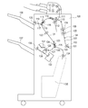
- FIG. 4 is a configuration diagram of a finisher 100 as a sheet processing apparatus.
- the finisher 100 includes a processing tray 138 as a second sheet stacking tray and a stapler 132 as a sheet processing unit.
- the finisher 100 further includes a lower discharge roller pair 128 as a sheet discharge unit and a pull-in paddle 131 as a return unit.
- the sheet S discharged from the image forming apparatus main body 600 is delivered to the entrance roller pair 102 of the finisher 100. At this time, the sheet delivery timing is simultaneously detected by the entrance sensor 101.
- the sheet S conveyed by the pair of entrance rollers 102 is detected by the edge detection sensor 104 while passing through the conveyance path 103 and the position of the edge in the width direction orthogonal to the sheet conveyance direction. Thus, it is detected how much the width direction error of the conveyed sheet S has occurred with respect to the conveyance center position in the width direction of the sheet processing apparatus.
- the sheet S is moved by a predetermined amount including the error in front / back of the width direction while the sheet S is being conveyed by the pair of shift rollers 105 and 106, and the sheet S A shift operation is performed.
- the sheet S conveyed by the conveying roller 110 and the separation roller 111 is conveyed by the second buffer roller pair 115.
- the switching member 118 is switched to a broken line state in the drawing by a driving unit such as a solenoid (not shown), and the sheet S is guided to the upper path conveyance path 117, and the upper discharge roller pair 120 is discharged to the upper discharge tray 136.
- the sheet S conveyed by the second buffer roller pair 115 is guided to the bundle conveyance path 121 by the switching member 118. Thereafter, the third buffer roller pair 122 and the bundle transport roller pair 124 sequentially pass through the transport path.
- the switching member 125 is switched to a broken line state by driving means such as a solenoid (not shown). Then, the sheet is conveyed to a saddle path 133 and guided to a saddle unit 135 by a pair of saddle entrance rollers 134 and subjected to saddle stitching (saddle) processing.
- the sheet S conveyed by the bundle conveying roller pair 124 is guided to the lower path 126 by the switching member 125. Thereafter, the sheet S discharged to the processing tray 138 as the second stacking tray by the lower discharge roller pair 128 is processed in the processing tray 138, and the lower discharge tray 137 is discharged by the discharge roller pair 130 as the conveying rotating body pair. To be discharged.
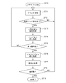
- FIG. 5 is a flowchart when a staple job in the finisher control unit is selected by the operation unit 601 of the image forming apparatus main body.
- a staple job (JOB) is selected (S710)
- printing is started in the image forming apparatus main body 600 (S711).
- S712 every time sheet discharge to the processing tray 138 of the finisher 100 is completed one by one (S712, YES), alignment processing by the front alignment plate 340 and the back alignment plate 341 is performed (S713).
- the paddle return process S714 by the pull-in paddle 131 is started.
- the stapler performs a binding process (S716), and the bundle is discharged (S717). If it is not the last sheet in the bundle (S715, NO), the operation of discharging the next sheet to the processing tray 138 is performed. This operation is repeated until the final bundle (S718, NO). If it is the final bundle (S718, YES), the staple job is terminated (S719).
- the first sheet S 1 conveyed by the conveying roller 110 and the separation roller 111 is guided to the bundle conveying path 121 by the second buffer roller pair 115.
- the leading edge of the sheet S1 is detected by the second buffer sensor 116, and the second buffer roller pair 115 is stopped so that the sheet stops when the trailing edge reaches the position A from the size information of the sheet recognized in advance.
- the stop control is performed (see FIG. 6A).
- the switching member 114 is switched to a broken line state by a driving means such as a solenoid (not shown), and the second buffer roller pair 115 performs the reverse rotation operation, whereby the upstream end (rear end) of the sheet S1 in the sheet conveyance direction before the reverse rotation operation. Guided to buffer path 113. Then, the sheet S1 is conveyed in the reverse direction until the downstream end (front end) in the sheet conveying direction of the sheet S1 before the reverse operation reaches the B point (see FIG. 6B).
- a driving means such as a solenoid
- the leading edge of the second sheet S2 being conveyed is detected by the first buffer sensor 109, the leading edge of the sheet S2 becomes the same position when the stopped sheet S1 reaches the conveying speed. Then, the first buffer roller pair 112 starts to be driven. As a result, the sheet S1 and the sheet S2 are in a state where the leading ends are aligned (see FIG. 6C).
- the second buffer roller pair 115 is driven until the trailing ends of the sheets S1 and S2 reach the A point. Thereafter, the above-described process is repeated to execute the third sheet superimposition process.
- a plurality of sheet bundles are conveyed to the processing tray unit or the saddle unit by the third buffer roller pair 122 and the bundle conveyance roller pair 124 downstream in the sheet conveyance direction. To go.
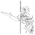
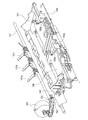
- the processing tray 138 as the second stacking tray has the downstream side (left side in FIG. 7) upward and the upstream side (right side in FIG. 7) downward with respect to the sheet conveyance direction of the sheet bundle. Inclined.
- a rear end stopper (regulating member) 150 is disposed at the upstream end of the processing tray 138 in the sheet conveying direction.
- a lower discharge roller 130 a of the discharge roller pair 130 is disposed at the downstream end of the processing tray 138 in the sheet conveyance direction.
- a guide guide 151 In the swing guide 149, a guide guide 151, a first static elimination needle 152, and a second static elimination needle 153 are arranged over the entire area in the axial direction.
- the swing guide 149 is rotatably supported by a support shaft 154 and can be swung in the vertical direction by a swing motor M149.
- the upper discharge roller 130b of the discharge roller pair 130 is disposed at the open end of the swingable guide 149 that can be opened and closed.
- the upper discharge roller 130b is moved relative to the lower discharge roller 130a as the swing guide 149 is opened and closed.
- the pair of discharge rollers 130 can be rotated forward and backward by rotational driving from the bundle sheet discharge drive motor M130 serving as drive means on the respective upper and lower discharge roller shafts.
- the discharge roller pair 130 can be discharged and conveyed in the discharge direction for discharging onto the lower discharge tray 137 and in the sheet conveyance direction for conveying onto the processing tray 138 opposite to the discharge direction.
- a belt roller 158 as a sheet conveying unit and a rear end lever 159 as a sheet pressing member are disposed on the upstream side of the processing tray 138 in the sheet conveying direction.
- the sheet hits the trailing edge stopper 150 while being guided by the trailing edge lever 159 by the rotation in the direction of moving the sheet in the direction opposite to the discharging direction of the lower discharging roller pair 128 of the belt roller 158, and the sheet conveying direction is aligned. Is done.
- the belt roller 158 is wound around the outer periphery of the discharge roller 128a constituting the lower discharge roller pair 128 as the sheet discharge means, and rotates following the rotation of the discharge roller 128a. Further, the belt roller 158 is provided above the processing tray 138 in such a positional relationship that the lower portion thereof is in contact with the uppermost sheet stacked on the processing tray 138.
- the stapler 132 is fixed on the slide abutment 303.
- rolling rollers 304 and 305 are provided at the lower part of the slide support 303.
- the slide support 303 is guided by the rolling rollers 304 and 305 and the guide rail groove 307 on the stapler moving table 306, and along the rear edge of the sheet S stacked on the processing tray 138 (in the direction of arrow Y). To).
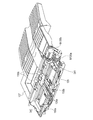
- FIG. 9 is a top view of the processing tray section. As shown in FIG. 9, the front side alignment plate 340 (first alignment member) and the back side alignment plate 341 (second alignment member) constituting the alignment unit are used to convey sheets stored in the processing tray 138. Align both ends in the width direction orthogonal to the direction.
- the first and second alignment members 340 and 341 are arranged on both sides of the sheet S on the processing tray 138.
- the first and second alignment members 340 and 341 have alignment surfaces 340a and 341a perpendicular to the stacking surface of the processing tray 138, and press the sheet side end.
- Alignment means has first and second alignment motors M340 and M341 that can drive the first and second alignment members 340 and 341 independently of each other.
- the driving force is transmitted from the leading pulleys of the alignment motors M340 and M341 to the first and second alignment members 340 and 341 via the timing belts B340 and B341.
- the alignment motors M340 and M341, the tip pulley, and the timing belts B340 and B341 constitute a driving unit.
- the first and second alignment members 340 and 341 can move independently along the sheet width direction with respect to the processing tray 138.
- the alignment surfaces 340a and 341a are arranged on the stacking surface of the processing tray 138 so as to face each other, and the driving means are assembled on the opposite side of the stacking surface so as to be able to move forward and backward in the width direction. .
- HP sensors S340 and S341 for detecting respective home positions are arranged for the first and second alignment members 340 and 341, respectively.
- the first and second alignment members 340 and 341 stand by at their respective home positions (both ends in the width direction of the processing tray 138).
- a plurality of lead-in paddles 131 (131a, 131b, 131c) are disposed above the processing tray 138, and a plurality of retractable paddles 131 are fixed on a rotating shaft 157 that is driven and connected by a gear train from the paddle drive motor M155. It is installed.
- the pull-in paddle 131 is a rotating body that rotates counterclockwise in FIG. 7 at an appropriate timing by the paddle drive motor M155.
- a plurality of drawing paddles 131 are provided along the axial direction of the rotating shaft 157.
- the plurality of pull-in paddles 131 contact the surface of the sheet evenly. There is nothing. Therefore, the sheet can be reliably abutted against the rear end stoppers 150a and 150b without being conveyed obliquely.
- sheets from the first page S11 of the first set discharged from the image forming apparatus main body 600 to a predetermined page thereafter are shifted by the shift unit 108 in either the front or back direction.
- One of them is sequentially conveyed while being shifted by a predetermined amount.
- the sheets S11 and S12 of the first and second pages are stacked so that the two sheets are stacked in a state where the end portions are shifted by the buffering process in the buffer path.
- the buffered sheets S11 and S12 are conveyed from the lower discharge roller pair 128 to the discharge roller pair 130.
- the two sheets have their rear ends passed through the lower discharge roller pair 128, and then the conveyance speed of the sheets contacting the upper discharge roller 130b and the lower discharge roller 130a is made constant by the forward rotation of the discharge roller pair 130, respectively. (FIG. 11A).
- the discharge roller pair 130 is rotated in the reverse direction, and is conveyed at a conveyance speed Vb in the direction opposite to the discharge direction of the discharge roller pair 130 so that the trailing edge of the sheet comes into contact with the trailing edge stopper 150.
- the swing guide 149 is raised to separate the upper discharge roller 130b and the lower discharge roller 130a.
- the conveyed sheet S11 slides toward the trailing edge stopper 150 due to the inclination of the stacking surface of the processing tray 138 and the inertial force of the conveyance speed Vb, and prevents the occurrence of buckling that is likely to occur particularly with a thin sheet. (FIG. 11B).
- the buffered sheet bundle is conveyed from the lower discharge roller pair 128 to the discharge roller pair 130, and is generated between the sheet bundles when the discharge roller pair 130 is abutted and aligned with the rear end stopper 150 by reverse conveyance. Details of the operation will be described later.
- the alignment in the width direction orthogonal to the sheet conveyance direction is performed by the first and second alignment members 340 and 341 ((FIG. 12 (a)).
- the sheet S13 of the third page of the first copy is discharged from the lower discharge roller pair 128 to the processing tray 138.
- the swing guide 149 is in the raised position, and the sheet S13 is greeted with the upper discharge roller 130b and the lower discharge roller 130a separated.
- the sheet S13 is discharged onto the processing tray 138.
- the sheet S13 discharged onto the processing tray 138 rotates in a direction in which the drawing paddle 131 moves the sheet in the direction opposite to the discharge direction of the lower discharge roller pair 128, so that the sheet end of the sheet S13 is moved to the trailing end stopper 150. (Fig. 12 (b)).
- the sheet S13 is further drawn to the rear end stopper 150 by the belt roller 158 that rotates in a direction to move the sheet in the direction opposite to the discharge direction, and abuts against the abutting surface of the rear end stopper 150 to be aligned.
- the alignment in the width direction is performed by the first and second alignment members 340 and 341 as in the sheets of S11 and S12. This series of operations is repeated until the final sheet S1n of the first copy hits the rear end stopper 150.
- the trailing edge of the sheet bundle S1T is stapled by the stapler 132. Then, as shown in FIG. 13A, the swing guide 149 is lowered, the sheet bundle S1T is sandwiched between the discharge roller pair 130, and discharged to the lower discharge tray 137 (FIG. 13B).
- the time required for the stapling operation after the last sheet S1n of the first part hits the trailing end stopper 150 and the bundle discharging operation to the lower discharge tray 137 of the first sheet bundle require extra processing time than the normal sheet processing. It is. During this time, the sheet S21 of the first page of the second copy cannot be received on the processing tray 138.
- the sheet discharged from the image forming apparatus main body 600 is buffered during the first sheet processing in the processing tray 138.
- a process of not discharging the sheet to the processing tray 138 is performed while sequentially receiving the next sheet from the image forming apparatus main body 600.
- the buffering processing that is originally necessary for transport control for the second and subsequent copies is performed on the first page and the second page of the first copy because the common transport control is performed in all the sections. is there.
- the conveyance of the sheet forming the first sheet bundle is started, if the sheet bundle is not being processed on the processing tray 138, it is necessary to buffer the first page and the second page sheet. Absent.
- the first page of the first page and the sheet of the second page are not buffered, it is necessary to change the conveyance control for the first part and the conveyance control for the second and subsequent copies in the buffering process.
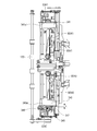
- FIG. 14 is a perspective view illustrating a detailed configuration of the discharge roller pair 130.
- the upper discharge roller 130b incorporates a one-way clutch 161, and is drivingly connected to the bundle discharge drive motor M130 together with the lower discharge roller 130a via a transmission gear provided on the rotating shaft.
- the one-way clutch 161 is locked only when the sheet is conveyed toward the trailing end stopper 150 by the discharge roller pair 130, and the rotational drive is directly transmitted to the upper discharge roller 130b by the bundle discharge drive motor M130. ing. Therefore, when the sheet is conveyed in the direction of the lower discharge tray 137 (first direction), the one-way clutch 161 is idled with respect to the rotation shaft, so that the upper discharge roller 130b has a clamping pressure with the lower discharge roller 130a. A rotational force with a dynamic friction coefficient ⁇ through the sheet is applied.
- FIG. 15 is an operation diagram when the sheet bundle is conveyed.
- the sheet conveyance speed of the upper discharge roller 130b and the lower discharge roller 130a has a speed difference of 5% due to the difference in roller diameter. That is, the movement distance per unit time of the sheet S12 that contacts the upper discharge roller 130b of the sheet bundle is larger than the movement distance per unit time of the sheet S11 that contacts the lower discharge roller 130a. Therefore, when the sheet bundle is conveyed in the direction of the trailing edge stopper 150 (second direction) by the discharge roller pair 130, a deviation in the sheet conveyance direction occurs between the sheets S11 and S12.
- the discharge roller pair 130 is reversed, and the distance at which the rear end of the sheet bundle contacts the rear end stopper 150 is set to about 100 mm.
- the distance at which the rear end of the sheet bundle contacts the rear end stopper 150 is set to about 100 mm.
- the conveyance speed of the abutting sheet is different, and no deviation occurs.
- the sheet conveyance speed difference between the upper discharge roller 130b and the lower discharge roller 130a is set to 5%, but any difference between the speed difference exceeding 5% or the speed difference below 5% is more than a certain value.
- a whispering effect can be expected. That is, the effect of the present invention can be obtained by conveying the sheet so as to have a speed difference between the conveying speed of the sheet contacting one of the discharge roller pair 130 and the speed of the sheet contacting the other.
- the amount of shift between the sheets subjected to the buffering process may affect the alignment at the time of abutting alignment with the trailing end stopper 150 of the sheet bundle, and depending on the sheet size, the basis weight of the sheet, the surface property, etc.
- the optimum shift amount is different. Therefore, in this embodiment, the shift amount during the buffering process and the shift amount due to the difference in the sheet conveyance amount between the upper discharge roller 130b and the lower discharge roller 130a can be changed. For example, as a method of changing the shift amount depending on the difference in the sheet conveyance amount, the discharge roller pair 130 is reversed, and the distance (in this embodiment, 100 mm) until the rear end of the sheet bundle contacts the rear end stopper 150 is changed. Thus, the shift amount can be changed.
- the roller diameter of the upper discharge roller 130b may be smaller than the roller diameter of the lower discharge roller 130a.
- the one-way clutch 161 is provided on the rotation shaft of the lower discharge roller 130a, and when the sheet is conveyed in the direction of the lower discharge tray 137, the lower discharge roller 130a is rotated so as to match the conveyance speed of the upper discharge roller 130b. If it is, the same effect will be acquired.
- FIG. 16 shows an embodiment according to the present invention.
- the first embodiment has a difference in roller diameter between the upper discharge roller and the lower discharge roller, and a one-way clutch is built in one of the discharge roller pair.
- the discharge roller pair is driven independently.
- the configuration different from that of the first embodiment will be described in detail, and the other configuration and operation are the same as those of the first embodiment, and thus description thereof will be omitted.
- the bundle discharge motors M130a and M130b of the upper discharge roller 130b and the lower discharge roller 130a are provided independently, and the conveyance speed is changed according to the conveyance direction. . That is, when the sheet is conveyed in the direction of the lower discharge tray 137 (first direction) by the discharge roller pair 130, the sheet conveyance speed by the upper discharge roller 130b and the lower discharge roller 130a is made equal. On the other hand, when the sheet bundle is conveyed by the discharge roller pair 130 in the direction of the trailing edge stopper 150 (second direction), a difference in conveyance speed between the upper discharge roller 130b and the lower discharge roller 130a is generated. Deviation in the sheet conveyance direction is generated.
- the upper discharge roller 130b and the lower discharge roller are also used when the trailing end of the two sheet bundles passes through the lower discharge roller pair 128 and then is conveyed by a predetermined amount by the discharge roller pair 130. It is possible to cause a difference in the sheet conveyance amount of 130a. Accordingly, it is possible to provide a rolling effect when the sheet bundle is conveyed in either the first direction or the second direction, and sticking between sheets can be prevented.
- FIG. 17 is a view of the moving mechanism of the swing guide 149 as viewed from the upstream side in the sheet conveying direction.
- a contact member 155 is provided on the same axis as the support shaft 154 of the swing guide 149, and moves in the slider 162 depending on the rotational position of the eccentric cam 156 that can be rotated by the discharge angle changing motor M160. It is possible. And it is always urged
- the abutting member 155 moves in the slider 162 together with the support shaft 154, and moves the swing guide 149.
- the contact member 155, the eccentric cam 156, and the discharge angle changing motor M160 constitute changing means.
- the roller nip position formed by the upper discharge roller 130b and the lower discharge roller 130a moves along the peripheral surface of the lower discharge roller 130a, and the discharge angle of the discharge roller pair 130 is variable. That is, the changing means can change the inclination of the line connecting the rotation centers of the upper discharge roller 130b and the lower discharge roller 130a.
- the first static elimination needle 152, the second static elimination needle 153, and the guide guide 151 attached to the swing guide 149 move together as the swing guide 149 moves. Therefore, the positional relationship between the first static elimination needle 152, the second static elimination needle 153, and the upper discharge roller 130b is not changed by the movement of the swing guide 149.
- the eccentric cam 156 is rotated and the contact member 155 is slid until the first sheet of the first copy of the job is discharged from the image forming apparatus 300.
- the swing guide 149 is moved.
- the operation of changing the discharge angle to the standby position is performed after the swing guide 149 is rotated upward about the support shaft 154 to bring the upper discharge roller 130b and the lower discharge roller 130a into a non-contact state. As shown in FIG.
- the swing guide 149 is rotated downward to bring the upper discharge roller 130b and the lower discharge roller 130a into contact with each other. That is, the discharge roller pair 130 stands by in a state where the angle (discharge nip angle) of the line connecting the rotation centers of the upper discharge roller 130b and the lower discharge roller 130a is ⁇ , and the first sheet of the job is the image forming apparatus. Wait for 300 to drain.
- the sheets subsequent to the sheet S11 forming the first copy discharged from the image forming apparatus main body 600 are shifted by a predetermined amount in the width direction orthogonal to the sheet conveying direction (to one side in the front / back direction in FIG. 2). It is conveyed sequentially.
- the second sheet S12 is placed on the first sheet S11, and the downstream end of the sheet S12 in the sheet conveying direction is 10 mm ahead of the downstream end of the sheet S11 in the sheet conveying direction, so-called roof tile. They are stacked to form a stack.
- the buffered sheets S ⁇ b> 11 and S ⁇ b> 12 are conveyed from the lower discharge roller pair 128 to the discharge roller pair 130 while being overlapped with a displacement of 10 mm.
- the two sheets S ⁇ b> 11 and S ⁇ b> 12 are conveyed by a predetermined distance by the discharge roller pair 130 after the upstream end (rear end) in the sheet conveyance direction passes through the lower discharge roller pair 128.
- the sheet S12 that comes into contact with the upper discharge roller 130b of the sheet bundle is shifted to the rear end stopper 150 side by 5 mm, so the amount of deviation between the sheets S11 and S12 when buffered 10mm becomes 5mm.
- the amount of deviation 10 mm between the sheets S11 and S12 when buffered is an error in the conveyance direction and even if a deviation amount of 5 mm due to the change in the discharge angle is added, the leading edge of the upper sheet S12 is more than the leading edge of the lower sheet S11. The preceding state does not reverse.
- the alignment in the sheet conveying direction is performed by maintaining the state where the leading edge of the upper sheet S12 is ahead of the leading edge of the lower sheet S11 and the inertia force after the separation between the upper discharge roller 130b and the lower discharge roller 130a and the processing tray 138.
- the pull-in paddle 131 and the belt roller 158 act on the upper sheet S12, and first abut the rear end of the lower sheet S11 against the rear end stopper 150, and then the upper sheet. Good matching is achieved by hitting S12.
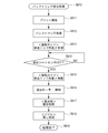
- FIG. 19 is a flowchart for explaining buffering sheet discharge control according to the third embodiment.
- the buffering discharge processing of the first sheet S11 and the second sheet S12 forming the sheet bundle is set (S810), printing from the image forming apparatus main body 600 starts ( S811) and buffering processing is performed (S812). Meanwhile, the upper discharge roller 130b and the lower discharge roller 130a stand by at a discharge nip angle ⁇ (S813), and sheet discharge to the processing tray portion of the finisher 100 is started.
- the changing means is provided in the upper discharge roller 130b, but the present invention is not limited to this.
- it is possible to shift the stacked sheets by providing a changing means in the lower discharge roller 130a and changing the contact position of the lower discharge roller 130a until the reverse rotation of the discharge roller pair 130 starts. is there. Further, while the driving of the discharge roller pair 130 is reversed and the two overlapped sheets are conveyed in the direction of the trailing edge stopper 150, the contact position of either the upper or lower discharge roller is set in the direction opposite to the sheet discharge direction. By changing, it is possible to shift the stacked sheets.
- the stacked sheets can be shifted by changing the contact position of either the upper or lower discharge roller in the same direction as the sheet discharge direction before the drive of the discharge roller pair 130 is reversed. Further, while the drive of the discharge roller pair 130 is reversed and conveyed in the direction of the trailing edge stopper 150, the contact position of either the upper or lower discharge roller is changed to the same direction as the sheet discharge direction, and the sheet is overlapped. It is possible to shift the sheets.
- the configuration in which the discharge roller pair is driven independently has been described. However, if at least one roller that moves along the other circumferential surface is driven by the bundle discharge drive motor, the stack is overlapped. It is possible to cause a shift in the sheet conveyance direction between the sheets.
Landscapes
- Engineering & Computer Science (AREA)
- Mechanical Engineering (AREA)
- Physics & Mathematics (AREA)
- General Physics & Mathematics (AREA)
- Pile Receivers (AREA)
- Folding Of Thin Sheet-Like Materials, Special Discharging Devices, And Others (AREA)
Abstract
Description
以下、本発明を実施するための形態について図面を用いて詳細に説明する。
図1は画像形成装置及びシート処理装置の構成図である。図1に示される画像形成装置は、白黒/カラー画像形成を行う画像形成装置本体600と、画像形成装置本体600にオンラインに接続され、画像形成装置本体600から排出されるシートに処理を施すシート処理装置(以下、フィニッシャという)100を備える。なお、画像形成装置本体600は、フィニッシャ100を排出口に接続せずに、単独でも使用できる。また、画像形成装置本体600は、フィニッシャ100をシート排出装置として一体に組み込んでもよい。
図2は画像形成装置を制御する画像形成装置制御部のブロック図である。
図2に示すように、CPU回路部630は、CPU629、ROM631、RAM655を有している。CPU回路部630は、原稿給送装置制御部632、イメージリーダ制御部633、画像信号制御部634、プリンタ制御部635、フィニッシャ制御部636、外部インターフェイス637を制御している。CPU回路部630は、ROM631に格納されているプログラム及び操作部601の設定に従って制御する。
図4はシート処理装置としてのフィニッシャ100の構成図である。図4に示すように、フィニッシャ100は、第二シート積載トレイとしての処理トレイ138とシート処理手段としてのステイプラ132を有している。フィニッシャ100は、さらに、シート排出手段としての下排出ローラ対128、戻し手段としての引き込みパドル131を有している。
図5はフィニッシャ制御部におけるステイプルジョブが画像形成装置本体の操作部601で選択された時のフローチャートである。図5に示すように、ステイプルジョブ(JOB)が選択されると(S710)、画像形成装置本体600でプリントが開始される(S711)。そして、フィニッシャ100の処理トレイ138へのシート排出が一枚ずつ完了される毎に(S712、YES)、手前側整合板340と奥側整合板341による整合処理が行われる(S713)。シートに対して幅方向の整合処理が終了すると、引き込みパドル131によるパドルの戻し処理(S714)が開始される。排出されたシートが束内の最終紙であれば(S715、YES)、ステイプラによる綴じ処理が行われ(S716)、束排出処理される(S717)。束内最終紙でなければ(S715、NO)、次のシートの処理トレイ138への排出動作が行われる。この動作を最終束まで繰り返し(S718、NO)、最終束であれば(S718、YES)、ステイプルJOBを終了する(S719)。
ステイプル処理やサドル処理を行う場合には、通常、ある一定の処理時間が必要となる。この処理時間は、画像形成装置における画像形成速度にも依存する部分はあるが、シート処理をシート排紙間隔の間で完了させることは困難であり、シート排紙間隔を超えるのが一般的である。このため、画像形成装置における画像形成動作を止めること無くシート処理を行うためにバッファリング(一時貯留)処理が行われる。
次に、処理トレイ部について図7~図10を用いて説明する。
ステイプルソートモードにおける、シートの流れを、図11を用いて説明する。
図16に、本発明に係る実施形態を表す。上述した第1の実施形態との違いは、第1の実施形態では上部排出ローラと下部排出ローラのローラ径に差をもたせるとともに、排出ローラ対の一方に一方向クラッチを内蔵させたのに対し、本実施の形態においては排出ローラ対を独立駆動とした点である。なお、ここでは、第1の実施形態と異なる構成を詳細に説明し、その他の構成及び動作は第1の実施形態と同じであるため説明は省略する。
次に、本発明に係る第3の実施形態について説明する。上述した第1及び第2の実施形態との違いは、第1及び第2の実施形態では排出ローラ対130の各ローラの速度差によりシート間にズレを発生させたのに対し、本実施の形態では排出ローラ対130のニップ角度の変更によりシート間にズレを発生させる点である。本実施の形態に係るシート処理装置においても、第2の実施形態と同様に、上部排出ローラ130bと下部排出ローラ130aの束排紙駆動モータM130a、M130bをそれぞれ独立に備え、搬送方向に応じて搬送速度を変えるようになっている。
図17は、揺動ガイド149の移動機構をシート搬送方向上流側から見た図である。図17に示すように、揺動ガイド149の支持軸154の同軸上には当接部材155が設けられ、排出角変更モータM160によって回転可能な偏芯カム156の回転位置によってスライダー162内で移動可能になっている。そして、不図示の付勢バネによって、常時、偏芯カム156に当接するように付勢されている。偏芯カム156の回転位置によって、当接部材155は支持軸154とともにスライダー162内を移動し、揺動ガイド149を移動させる。当接部材155、偏芯カム156、排出角変更モータM160は変更手段を構成する。
上記変更手段の動作により、上部排出ローラ130bと下部排出ローラ130aによって形成されるローラニップ位置が下部排出ローラ130aの周面に沿って移動し、排出ローラ対130の排出角度を可変にしている。つまり、変更手段は上部排出ローラ130bと下部排出ローラ130aの各回転中心を結ぶ線の傾きを変更可能である。揺動ガイド149に取り付けられている第一除電針152、第二除電針153、案内ガイド151は、揺動ガイド149の移動に伴って一体で移動する。よって、第一除電針152、第二除電針153と上部排出ローラ130bとの位置関係は揺動ガイド149の移動によって変わることがない。
次に、本実施形態におけるステイプルソートモード時のシートの流れを、図18(a)、図18(b)を用いて説明する。
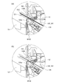
ステイプルソートモードのジョブが選択されると、ジョブの1部目の最初のシートが画像形成装置300から排出されるまでに、偏芯カム156を回転させて、当接部材155をスライドさせることにより揺動ガイド149を移動させる。待機位置への排出角度の変更動作は、支持軸154中心に揺動ガイド149を上方へ回動させ、上部排出ローラ130bと下部排出ローラ130aを非接触状態にしてから行われる。
図18(a)に示すように、待機位置への排出角度変更動作が終了すると、揺動ガイド149を下方に回動させて、上部排出ローラ130bと下部排出ローラ130aを当接させる。すなわち、排出ローラ対130は、上部排出ローラ130bと下部排出ローラ130aを各々の回転中心を結んだ線の角度(排出ニップ角度)がβの状態で待機し、ジョブの最初のシートが画像形成装置300から排出されるのを待つ。
画像形成装置本体600から排出された1部目を形成するシートS11以降のシートは、シフトユニット108によりシート搬送方向と直交する幅方向に(図2の前/奥方向片側に)所定量シフトされながら順次搬送される。そして、バッファパス内で、1枚目のシートS11の上に2枚目のシートS12を、シートS12のシート搬送方向下流端がシートS11のシート搬送方向下流端よりも10mm先行した状態、いわゆる瓦積みになるように重ね合わされる。バッファリングされたシートS11、S12は、ズレ量10mmの状態で重なったまま下排出ローラ対128から排出ローラ対130に搬送される。
図18(b)に示すように、2枚のシートS11とS12はシート搬送方向上流端(後端)が下排出ローラ対128を抜けてから排出ローラ対130によって所定距離、搬送される。具体的には、シートS11は下部排出ローラ130aの搬送速度VI=300m/s、シートS12は上部排出ローラ130bの搬送速度VII=300m/sで時間T=100msの間、距離L1=30mmを搬送される。
排出ローラ対130によってシートS11とS12を搬送する間に、揺動ガイド149は変更手段によって排出角度変更の動作を行う。上部排出ローラ130bは移動速度VIII=100m/sで時間T=50msの間に、下部排出ローラ130aの外周円上を距離L2=5mm移動しながら排出ニップ角度をβからγの状態にする。揺動ガイド149の排出角度変更の動作により、シート束の上部排出ローラ130bに当接するシートS12は、5mm後端ストッパ150側へずらされるため、バッファリングされたときのシートS11とS12のズレ量10mmは5mmになる。バッファリングされたときのシートS11とS12のズレ量10mmは搬送方向の誤差、及び排出角度変更による5mmのズレ量が加わったとしても上側のシートS12の先端が下側のシートS11の先端よりも先行する状態が逆転することはない。表面性の良いコート紙や、フィルム同士をバッファリングによって重ね合わせて処理トレイ138へ搬送中にシート間で貼り付きが発生した場合でも、後端ストッパ150に当接する前にシート間で5mmのずらすことによって捌き効果を付与することができる。
このように、上部排出ローラ130bと下部排出ローラ130aにより重ねたシートを搬送している間に、各々の回転中心を結んだ線の傾きを変更することにより重ねたシートをシート搬送方向にずらすことができる。そして、手前側/奥側の整合板340、341による整合、後端ストッパ150への当接の前に貼り付きを解消することによって、重ね合わされたシートの端部を容易に整合することが可能となる。シート搬送方向の整合は、上側のシートS12の先端が下側のシートS11の先端よりも先行する状態を保ったまま、上部排出ローラ130bと下部排出ローラ130aの離間後の慣性力と処理トレイ138の積載面の傾斜により後端ストッパ150に向かう。シート搬送方向の整合を行う際は、引き込みパドル131とベルトローラ158が上側のシートS12に作用して、まず下側のシートS11の後端を後端ストッパ150に突き当てた後、上側のシートS12を突き当てることによって良好な整合が行われる。
その後は、実施形態1と同様、1部目の3ページ以降のシートの整合積載、さらに、必要に応じて綴じ処理を行って下排出トレイ137に束排出する。
(バッファリングシート排出制御)
図19は第3の実施形態に係るバッファリングシートの排出制御を説明するフローチャートである。図19に示すように、シート束を形成する1枚目のシートS11と2枚目のシートS12のバッファリング排出処理が設定される(S810)と、画像形成装置本体600からのプリントが開始(S811)され、バッファリング処理が行われる(S812)。その間、上部排出ローラ130bと下部排出ローラ130aは排出ニップ角度βの状態で待機(S813)し、フィニッシャ100の処理トレイ部へのシート排出が開始される。シートS11、S12が排出シート検知センサ127(図4)を通過(S814、YES)し、後端が下排出ローラ対128を抜けると、排出角変更手段によってニップ角度γの位置に移動する(S815)。シートの処理トレイ138への排出が完了されると上部排出ローラ130bと下部排出ローラ130aは離間(S816)し、手前側整合板340と奥側整合板341による幅整合処理が行われる(S817)。シートS11、S12に対して幅方向の整合処理が終了すると引き込みパドル131による、パドルの戻し処理(S818)が開始される。シートS11、S12の後端が後端ストッパ150へ当接して処理が完了(S819)する。
本実施の形態においては、上部排出ローラ130bに変更手段を設けたが、これに限らない。例えば、下部排出ローラ130aに変更手段を設け、排出ローラ対130の逆回転が開始するまでに、下部排出ローラ130aの当接位置を変更することで、重ねられたシート同士をずらすことが可能である。
また、排出ローラ対130の駆動が逆転し、重ねられた2枚のシートを後端ストッパ150の方向に搬送する間に、上下いずれかの排出ローラの当接位置をシート排出方向と逆方向に変更することで、重ねられたシートをずらすことが可能である。
また、排出ローラ対130の駆動が逆転するまでに、上下いずれかの排出ローラの当接位置をシートの排出方向と同じ方向に変更することで、重ねられたシートをずらすことが可能である。
さらに、排出ローラ対130の駆動が逆転し、後端ストッパ150方向に搬送する間に、上下いずれかの排出ローラの当接位置をシートの排出方向と同じ方向に変更することで、重ねられたシート同士をずらすことが可能である。
本実施の形態においては排出ローラ対を独立駆動とした構成について説明したが、少なくとも他方の周面に沿って移動する一方のローラが束排紙駆動モータによって駆動される構成であれば、重ねたシート間にシート搬送方向のズレを生じさせることが可能である。
105、106 シフトローラ対
108 シフトユニット
109 第1バッファセンサ
110 搬送ローラ
111 離間ローラ
112 第1バッファローラ対
113 バッファパス
114 切替部材
115 第2バッファローラ対
116 第2バッファセンサ
122 第3バッファローラ対
130 排出ローラ対
131 パドル
132 ステイプラ
136 上排出トレイ
137 下排出トレイ
138 処理トレイ
149 揺動ガイド
150 後端ストッパ
600 画像形成装置本体
Claims (11)
- 複数のシートを重ねた状態で搬送可能な搬送回転体対と、
前記搬送回転体対により搬送されたシートを積載する積載トレイと、
前記積載トレイに搬送されたシートを突き当てて規制する規制部材を備え、
前記搬送回転体対は、重ねたシート間にシート搬送方向のズレを生じさせた後、重ねたシートを前記規制部材に向かって搬送することを特徴とするシート処理装置。 - 前記搬送回転体対は、重ねて搬送されるシートのうち前記搬送回転体対の一方の回転体に当接するシートと他方の回転体に当接するシートに速度差が生ずるよう搬送して重ねたシート間にズレを生じさせることを特徴とする請求項1に記載のシート処理装置。
- 前記搬送回転体対の一方の回転体と他方の回転体は各々異なる径を有し、前記搬送回転体対の一方の回転体と他方の回転体のいずれかに一方向クラッチを備えたことを特徴とする請求項2に記載のシート処理装置。
- 前記搬送回転体対は各々独立に駆動されることを特徴とする請求項2に記載のシート処理装置。
- 前記搬送回転体対の各々の回転中心を結ぶ線の傾きを変更する変更手段を備え、前記変更手段は、前記回転中心を結ぶ線の傾きを変更して重ねたシート間にズレを生じさせることを特徴とする請求項1に記載のシート処理装置。
- 前記変更手段は、前記搬送回転体対の一方の回転体を他方の回転体の周面に沿って移動させることにより重ねたシート同士をずらすことを特徴とする請求項5に記載のシート処理装置。
- 前記搬送回転体対は正逆回転可能であり、正回転により前記積載トレイに重ねて搬送されたシートを逆回転により前記規制部材に向かって搬送することを特徴とする請求項1乃至6のいずれか1項にシート処理装置。
- 前記搬送回転体対は、重ねたシートの前記規制部材に当接する端部のうち、下側のシートの端部が上側のシートの端部よりも前記規制部材に近くなるようずらした状態で前記規制部材に向かって搬送することを特徴とした請求項1乃至7のいずれか1項に記載のシート束搬送装置
- 前記搬送回転体対は、重ねたシートが前記規制部材に突き当てられる前に、互いに離間することを特徴とする請求項1乃至8のいずれか1項に記載のシート処理装置。
- 前記積載トレイに積載されたシートを処理するシート処理手段を備え、前記シート処理手段は、前記規制部材に規制されたシートに処理を施すことを特徴とする請求項1乃至9のいずれか1項に記載のシート処理装置。
- シートに画像を形成する画像形成手段と、
画像形成されたシートを処理する請求項1乃至10のいずれか1項に記載のシート処理装置と、を備えたことを特徴とする画像形成装置。
Priority Applications (4)
| Application Number | Priority Date | Filing Date | Title |
|---|---|---|---|
| CN201080055055.2A CN102639419B (zh) | 2009-12-08 | 2010-02-19 | 片材处理装置及装备有片材处理装置的成像装置 |
| JP2011545100A JP5451777B2 (ja) | 2009-12-08 | 2010-02-19 | シート処理装置、及びそれを備えた画像形成装置 |
| US12/960,360 US8267399B2 (en) | 2009-12-08 | 2010-12-03 | Sheet processing apparatus and image forming apparatus including same |
| US13/588,433 US8616547B2 (en) | 2009-12-08 | 2012-08-17 | Sheet processing apparatus and image forming apparatus including same |
Applications Claiming Priority (2)
| Application Number | Priority Date | Filing Date | Title |
|---|---|---|---|
| JP2009070572 | 2009-12-08 | ||
| JPPCT/JP2009/070572 | 2009-12-08 |
Publications (1)
| Publication Number | Publication Date |
|---|---|
| WO2011070799A1 true WO2011070799A1 (ja) | 2011-06-16 |
Family
ID=44145355
Family Applications (1)
| Application Number | Title | Priority Date | Filing Date |
|---|---|---|---|
| PCT/JP2010/052560 Ceased WO2011070799A1 (ja) | 2009-12-08 | 2010-02-19 | シート処理装置、及びそれを備えた画像形成装置 |
Country Status (3)
| Country | Link |
|---|---|
| US (2) | US8267399B2 (ja) |
| CN (1) | CN102639419B (ja) |
| WO (1) | WO2011070799A1 (ja) |
Cited By (1)
| Publication number | Priority date | Publication date | Assignee | Title |
|---|---|---|---|---|
| JP2013060304A (ja) * | 2011-08-23 | 2013-04-04 | Canon Inc | シート処理装置及び画像形成装置 |
Families Citing this family (13)
| Publication number | Priority date | Publication date | Assignee | Title |
|---|---|---|---|---|
| CN102639419B (zh) * | 2009-12-08 | 2015-02-25 | 佳能株式会社 | 片材处理装置及装备有片材处理装置的成像装置 |
| US11220409B2 (en) * | 2011-10-31 | 2022-01-11 | Ncr Corporation | Single item removal |
| JP6019606B2 (ja) * | 2012-02-14 | 2016-11-02 | 富士ゼロックス株式会社 | 後処理装置および画像形成装置 |
| JP6318696B2 (ja) | 2013-06-07 | 2018-05-09 | 株式会社リコー | 用紙処理装置、画像形成システム及び用紙搬送方法 |
| JP6235900B2 (ja) * | 2013-12-27 | 2017-11-22 | キヤノンファインテックニスカ株式会社 | シート綴じ処理装置及びこれを用いた画像形成システム |
| JP2015182883A (ja) * | 2014-03-26 | 2015-10-22 | 富士ゼロックス株式会社 | 記録材排出装置及びこれを用いた記録材処理装置 |
| JP6486017B2 (ja) * | 2014-05-27 | 2019-03-20 | 理想科学工業株式会社 | 排紙装置 |
| US10197961B2 (en) * | 2016-02-16 | 2019-02-05 | Canon Kabushiki Kaisha | Image forming apparatus |
| JP6731274B2 (ja) * | 2016-04-18 | 2020-07-29 | シャープ株式会社 | 駆動伝達機構、シート排出装置及び画像形成装置 |
| JP6493294B2 (ja) * | 2016-04-27 | 2019-04-03 | 京セラドキュメントソリューションズ株式会社 | シート整合装置、画像形成装置 |
| JP6847640B2 (ja) | 2016-11-25 | 2021-03-24 | 株式会社東芝 | シートさばき装置、シート後処理装置、および画像形成装置 |
| US10604369B2 (en) * | 2016-12-09 | 2020-03-31 | Canon Finetech Nisca Inc. | Apparatus for processing sheets and apparatus for forming images provided with the apparatus |
| US10042305B2 (en) * | 2016-12-28 | 2018-08-07 | Kabushiki Kaisha Toshiba | Sheet processing device and sheet processing method |
Citations (3)
| Publication number | Priority date | Publication date | Assignee | Title |
|---|---|---|---|---|
| JPS60236969A (ja) * | 1984-05-08 | 1985-11-25 | Ishikawajima Harima Heavy Ind Co Ltd | パイラにおけるオ−バ−ラツプ板分離方法及び装置 |
| JP2002037512A (ja) * | 2000-07-21 | 2002-02-06 | Canon Aptex Inc | シート後処理装置とこの装置を備えた画像形成装置 |
| JP2002187663A (ja) * | 2000-12-22 | 2002-07-02 | Nippon Signal Co Ltd:The | 複数枚媒体の分離機構 |
Family Cites Families (23)
| Publication number | Priority date | Publication date | Assignee | Title |
|---|---|---|---|---|
| JPH06179546A (ja) * | 1992-12-15 | 1994-06-28 | Ace Denken:Kk | 紙片幅寄せ機構及び紙片搬送装置 |
| US6241234B1 (en) * | 1996-12-27 | 2001-06-05 | Canon Kabushiki Kaisha | Sheet processing apparatus and image forming apparatus using same |
| KR200156004Y1 (ko) * | 1997-10-07 | 1999-09-01 | 윤종용 | 양면인쇄장치의 용지가이드 |
| JPH11322165A (ja) | 1998-05-13 | 1999-11-24 | Canon Aptex Inc | シート処理装置及び画像形成装置 |
| JP3774613B2 (ja) * | 2000-02-29 | 2006-05-17 | キヤノン株式会社 | 記録装置 |
| TW581740B (en) * | 2002-02-28 | 2004-04-01 | Canon Denshi Kk | Sheet feeding apparatus and image forming apparatus and image reading apparatus provided with the same |
| JP2003300658A (ja) | 2002-04-11 | 2003-10-21 | Canon Inc | シート処理装置 |
| US6909872B2 (en) * | 2002-10-30 | 2005-06-21 | Hewlett-Packard Development Company, L.P. | Multipath printers |
| WO2004069709A1 (en) * | 2003-02-03 | 2004-08-19 | Hewlett-Packard Development Company, L.P. | Print media flipping mechanism and method |
| JP4298360B2 (ja) * | 2003-03-07 | 2009-07-15 | キヤノンファインテック株式会社 | シート処理装置及び該装置を備えた画像形成装置 |
| US7258335B2 (en) * | 2004-08-24 | 2007-08-21 | Lexmark International, Inc. | Eliminating drag of media sensor in printer media transport |
| EP1930262B1 (de) * | 2006-12-08 | 2011-08-03 | Adolf Mohr Maschinenfabrik GmbH & Co. KG | Vorrichtung zum Aufbrechen und Belüften eines aus Blättern gebildeten Materialstapels |
| US20080317530A1 (en) * | 2007-06-19 | 2008-12-25 | Kabushiki Kaisha Toshiba | Fastening structure for rotating member |
| US7717423B2 (en) * | 2007-09-27 | 2010-05-18 | Lexmark International, Inc. | Duplex ADF mechanism |
| JP5031522B2 (ja) * | 2007-11-07 | 2012-09-19 | キヤノン株式会社 | シート排出装置、シート処理装置、画像形成装置 |
| JP5301975B2 (ja) * | 2008-12-11 | 2013-09-25 | ニスカ株式会社 | シート集積方法、シート集積装置および後処理装置並びに画像形成システム |
| JP2010260680A (ja) * | 2009-05-01 | 2010-11-18 | Konica Minolta Business Technologies Inc | 画像形成装置 |
| CN102639419B (zh) * | 2009-12-08 | 2015-02-25 | 佳能株式会社 | 片材处理装置及装备有片材处理装置的成像装置 |
| JP5282755B2 (ja) * | 2010-03-29 | 2013-09-04 | 富士ゼロックス株式会社 | シート処理装置およびシート処理システム |
| JP5499910B2 (ja) * | 2010-05-31 | 2014-05-21 | ブラザー工業株式会社 | 搬送装置及びこの搬送装置を備えた画像記録装置 |
| JP5240243B2 (ja) * | 2010-06-17 | 2013-07-17 | ブラザー工業株式会社 | 画像記録装置 |
| JP4998600B2 (ja) * | 2010-06-17 | 2012-08-15 | ブラザー工業株式会社 | 画像記録装置 |
| JP5921128B2 (ja) * | 2011-10-07 | 2016-05-24 | コニカミノルタ株式会社 | シート収納装置及びこれを用いた画像形成システム |
-
2010
- 2010-02-19 CN CN201080055055.2A patent/CN102639419B/zh not_active Expired - Fee Related
- 2010-02-19 WO PCT/JP2010/052560 patent/WO2011070799A1/ja not_active Ceased
- 2010-12-03 US US12/960,360 patent/US8267399B2/en not_active Expired - Fee Related
-
2012
- 2012-08-17 US US13/588,433 patent/US8616547B2/en not_active Expired - Fee Related
Patent Citations (3)
| Publication number | Priority date | Publication date | Assignee | Title |
|---|---|---|---|---|
| JPS60236969A (ja) * | 1984-05-08 | 1985-11-25 | Ishikawajima Harima Heavy Ind Co Ltd | パイラにおけるオ−バ−ラツプ板分離方法及び装置 |
| JP2002037512A (ja) * | 2000-07-21 | 2002-02-06 | Canon Aptex Inc | シート後処理装置とこの装置を備えた画像形成装置 |
| JP2002187663A (ja) * | 2000-12-22 | 2002-07-02 | Nippon Signal Co Ltd:The | 複数枚媒体の分離機構 |
Cited By (1)
| Publication number | Priority date | Publication date | Assignee | Title |
|---|---|---|---|---|
| JP2013060304A (ja) * | 2011-08-23 | 2013-04-04 | Canon Inc | シート処理装置及び画像形成装置 |
Also Published As
| Publication number | Publication date |
|---|---|
| US8267399B2 (en) | 2012-09-18 |
| US8616547B2 (en) | 2013-12-31 |
| CN102639419A (zh) | 2012-08-15 |
| CN102639419B (zh) | 2015-02-25 |
| US20110133392A1 (en) | 2011-06-09 |
| US20120313311A1 (en) | 2012-12-13 |
Similar Documents
| Publication | Publication Date | Title |
|---|---|---|
| WO2011070799A1 (ja) | シート処理装置、及びそれを備えた画像形成装置 | |
| JP5031522B2 (ja) | シート排出装置、シート処理装置、画像形成装置 | |
| JP5344571B2 (ja) | シート積載装置及びこれを備えるシート処理装置 | |
| US8651480B2 (en) | Sheet stacking apparatus and image forming apparatus | |
| US7887037B2 (en) | Sheet process apparatus | |
| JP5812749B2 (ja) | シート処理装置及び画像形成装置 | |
| JP6041587B2 (ja) | シート処理装置及び画像形成装置 | |
| US8205867B2 (en) | Sheet processing apparatus and image forming apparatus | |
| JP5566509B2 (ja) | シート処理装置及び画像形成装置 | |
| US9139396B2 (en) | Sheet processing apparatus and image forming apparatus | |
| JP5295326B2 (ja) | シート処理装置及び画像形成装置 | |
| JP4827646B2 (ja) | シート積載装置とシート処理装置、及びそれらを備えた画像形成装置 | |
| JP2013060303A (ja) | シート処理装置及び画像形成装置 | |
| JP5451777B2 (ja) | シート処理装置、及びそれを備えた画像形成装置 | |
| JP5506862B2 (ja) | シート排出装置、シート処理装置、画像形成装置 | |
| JP5804829B2 (ja) | シート処理装置及び画像形成装置 | |
| JP5987458B2 (ja) | 用紙処理装置及び画像形成システム | |
| JP2009113924A (ja) | シート排出装置、シート処理装置、画像形成装置 | |
| JP2009126659A (ja) | シート排出装置、シート処理装置及び画像形成装置 | |
| JP2013159443A (ja) | シート処理装置及び画像形成装置 | |
| JP2009051578A (ja) | シート整合装置、シート処理装置、及び画像形成装置 |
Legal Events
| Date | Code | Title | Description |
|---|---|---|---|
| WWE | Wipo information: entry into national phase |
Ref document number: 201080055055.2 Country of ref document: CN |
|
| 121 | Ep: the epo has been informed by wipo that ep was designated in this application |
Ref document number: 10835722 Country of ref document: EP Kind code of ref document: A1 |
|
| WWE | Wipo information: entry into national phase |
Ref document number: 2011545100 Country of ref document: JP |
|
| NENP | Non-entry into the national phase |
Ref country code: DE |
|
| 122 | Ep: pct application non-entry in european phase |
Ref document number: 10835722 Country of ref document: EP Kind code of ref document: A1 |