WO2011068154A1 - 蓄電ユニット、発電システムおよび充放電システム - Google Patents
蓄電ユニット、発電システムおよび充放電システム Download PDFInfo
- Publication number
- WO2011068154A1 WO2011068154A1 PCT/JP2010/071563 JP2010071563W WO2011068154A1 WO 2011068154 A1 WO2011068154 A1 WO 2011068154A1 JP 2010071563 W JP2010071563 W JP 2010071563W WO 2011068154 A1 WO2011068154 A1 WO 2011068154A1
- Authority
- WO
- WIPO (PCT)
- Prior art keywords
- power
- storage unit
- power storage
- converter
- unit
- Prior art date
- Legal status (The legal status is an assumption and is not a legal conclusion. Google has not performed a legal analysis and makes no representation as to the accuracy of the status listed.)
- Ceased
Links
Images
Classifications
-
- H—ELECTRICITY
- H02—GENERATION; CONVERSION OR DISTRIBUTION OF ELECTRIC POWER
- H02J—ELECTRIC POWER NETWORKS; CIRCUIT ARRANGEMENTS OR SYSTEMS FOR SUPPLYING OR DISTRIBUTING ELECTRIC POWER; SYSTEMS FOR STORING ELECTRIC ENERGY
- H02J3/00—Circuit arrangements for AC mains or AC distribution networks
- H02J3/28—Arrangements for balancing of the load in networks by storage of energy
- H02J3/32—Arrangements for balancing of the load in networks by storage of energy using batteries or super capacitors with converting means
-
- H—ELECTRICITY
- H01—ELECTRIC ELEMENTS
- H01M—PROCESSES OR MEANS, e.g. BATTERIES, FOR THE DIRECT CONVERSION OF CHEMICAL ENERGY INTO ELECTRICAL ENERGY
- H01M10/00—Secondary cells; Manufacture thereof
- H01M10/60—Heating or cooling; Temperature control
- H01M10/61—Types of temperature control
- H01M10/613—Cooling or keeping cold
-
- H—ELECTRICITY
- H01—ELECTRIC ELEMENTS
- H01M—PROCESSES OR MEANS, e.g. BATTERIES, FOR THE DIRECT CONVERSION OF CHEMICAL ENERGY INTO ELECTRICAL ENERGY
- H01M10/00—Secondary cells; Manufacture thereof
- H01M10/60—Heating or cooling; Temperature control
- H01M10/65—Means for temperature control structurally associated with the cells
- H01M10/656—Means for temperature control structurally associated with the cells characterised by the type of heat-exchange fluid
- H01M10/6561—Gases
- H01M10/6563—Gases with forced flow, e.g. by blowers
-
- H—ELECTRICITY
- H01—ELECTRIC ELEMENTS
- H01M—PROCESSES OR MEANS, e.g. BATTERIES, FOR THE DIRECT CONVERSION OF CHEMICAL ENERGY INTO ELECTRICAL ENERGY
- H01M14/00—Electrochemical current or voltage generators not provided for in groups H01M6/00 - H01M12/00; Manufacture thereof
- H01M14/005—Photoelectrochemical storage cells
-
- H—ELECTRICITY
- H01—ELECTRIC ELEMENTS
- H01M—PROCESSES OR MEANS, e.g. BATTERIES, FOR THE DIRECT CONVERSION OF CHEMICAL ENERGY INTO ELECTRICAL ENERGY
- H01M16/00—Structural combinations of different types of electrochemical generators
-
- H—ELECTRICITY
- H05—ELECTRIC TECHNIQUES NOT OTHERWISE PROVIDED FOR
- H05K—PRINTED CIRCUITS; CASINGS OR CONSTRUCTIONAL DETAILS OF ELECTRIC APPARATUS; MANUFACTURE OF ASSEMBLAGES OF ELECTRICAL COMPONENTS
- H05K7/00—Constructional details common to different types of electric apparatus
- H05K7/20—Modifications to facilitate cooling, ventilating, or heating
- H05K7/2089—Modifications to facilitate cooling, ventilating, or heating for power electronics, e.g. for inverters for controlling motor
- H05K7/20909—Forced ventilation, e.g. on heat dissipaters coupled to components
-
- H—ELECTRICITY
- H02—GENERATION; CONVERSION OR DISTRIBUTION OF ELECTRIC POWER
- H02J—ELECTRIC POWER NETWORKS; CIRCUIT ARRANGEMENTS OR SYSTEMS FOR SUPPLYING OR DISTRIBUTING ELECTRIC POWER; SYSTEMS FOR STORING ELECTRIC ENERGY
- H02J2101/00—Supply or distribution of decentralised, dispersed or local electric power generation
- H02J2101/20—Dispersed power generation using renewable energy sources
- H02J2101/28—Wind energy
-
- H—ELECTRICITY
- H02—GENERATION; CONVERSION OR DISTRIBUTION OF ELECTRIC POWER
- H02J—ELECTRIC POWER NETWORKS; CIRCUIT ARRANGEMENTS OR SYSTEMS FOR SUPPLYING OR DISTRIBUTING ELECTRIC POWER; SYSTEMS FOR STORING ELECTRIC ENERGY
- H02J3/00—Circuit arrangements for AC mains or AC distribution networks
- H02J3/38—Arrangements for feeding a single network from two or more generators or sources in parallel; Arrangements for feeding already energised networks from additional generators or sources in parallel
- H02J3/381—Dispersed generators
-
- Y—GENERAL TAGGING OF NEW TECHNOLOGICAL DEVELOPMENTS; GENERAL TAGGING OF CROSS-SECTIONAL TECHNOLOGIES SPANNING OVER SEVERAL SECTIONS OF THE IPC; TECHNICAL SUBJECTS COVERED BY FORMER USPC CROSS-REFERENCE ART COLLECTIONS [XRACs] AND DIGESTS
- Y02—TECHNOLOGIES OR APPLICATIONS FOR MITIGATION OR ADAPTATION AGAINST CLIMATE CHANGE
- Y02E—REDUCTION OF GREENHOUSE GAS [GHG] EMISSIONS, RELATED TO ENERGY GENERATION, TRANSMISSION OR DISTRIBUTION
- Y02E10/00—Energy generation through renewable energy sources
- Y02E10/70—Wind energy
- Y02E10/76—Power conversion electric or electronic aspects
-
- Y—GENERAL TAGGING OF NEW TECHNOLOGICAL DEVELOPMENTS; GENERAL TAGGING OF CROSS-SECTIONAL TECHNOLOGIES SPANNING OVER SEVERAL SECTIONS OF THE IPC; TECHNICAL SUBJECTS COVERED BY FORMER USPC CROSS-REFERENCE ART COLLECTIONS [XRACs] AND DIGESTS
- Y02—TECHNOLOGIES OR APPLICATIONS FOR MITIGATION OR ADAPTATION AGAINST CLIMATE CHANGE
- Y02E—REDUCTION OF GREENHOUSE GAS [GHG] EMISSIONS, RELATED TO ENERGY GENERATION, TRANSMISSION OR DISTRIBUTION
- Y02E60/00—Enabling technologies; Technologies with a potential or indirect contribution to GHG emissions mitigation
- Y02E60/10—Energy storage using batteries
-
- Y—GENERAL TAGGING OF NEW TECHNOLOGICAL DEVELOPMENTS; GENERAL TAGGING OF CROSS-SECTIONAL TECHNOLOGIES SPANNING OVER SEVERAL SECTIONS OF THE IPC; TECHNICAL SUBJECTS COVERED BY FORMER USPC CROSS-REFERENCE ART COLLECTIONS [XRACs] AND DIGESTS
- Y02—TECHNOLOGIES OR APPLICATIONS FOR MITIGATION OR ADAPTATION AGAINST CLIMATE CHANGE
- Y02E—REDUCTION OF GREENHOUSE GAS [GHG] EMISSIONS, RELATED TO ENERGY GENERATION, TRANSMISSION OR DISTRIBUTION
- Y02E70/00—Other energy conversion or management systems reducing GHG emissions
- Y02E70/30—Systems combining energy storage with energy generation of non-fossil origin
Definitions
- the present invention relates to a power storage unit, a power generation system, and a charge / discharge system, and more particularly, to a power storage unit, a power generation system, and a charge / discharge system including a power storage unit capable of storing power.
- a power generation system including a storage battery capable of storing electric power is known.
- Such a power generation system is disclosed in, for example, Japanese Patent Application Laid-Open No. 11-127546.
- the photovoltaic power generation module is linked to the power system.
- a storage battery is connected to the solar power generation module so that the power generated by the solar power generation module can be stored.
- the storage battery is configured to be able to be charged from the power system. Further, the storage battery can be discharged in a predetermined case to supply power to a predetermined load.
- One object of the present invention is to provide a power storage unit, a power generation system, and a charge / discharge system capable of suppressing adverse effects on the power storage unit itself even when the power storage unit is housed in a housing. It is.
- a power storage unit includes a power storage unit that stores power, a converter that converts power, a first temperature detection unit disposed in the vicinity of the converter, at least a converter, a first temperature detection unit, and A housing for storing the power storage unit.
- the vicinity of the converter represents the range of a distance half the longest of the distances from the converter to the inner wall of the housing with the converter as the center.
- a power generation system is arranged in the vicinity of a power generation module that is connected to a power system and generates power using natural energy, a power storage unit that stores power, a converter that converts power, and a converter. And a power storage unit including at least a converter, a housing for storing the first temperature detection unit, and the power storage unit.
- a charge / discharge system includes a power storage unit that stores electric power, a converter that converts electric power, a first temperature detection unit disposed in the vicinity of the converter, at least a converter, and a first temperature detection unit. And a storage unit including a housing for storing the storage unit, and a control unit that controls a converter included in the storage unit, wherein the control unit detects a temperature detected by the first temperature detection unit equal to or higher than a predetermined first threshold value. When it is determined that it has become, the converter drive is stopped.
- the increase in temperature of the power storage unit can be suppressed, so that the function of the power storage unit can be prevented from being lowered and the power storage unit can be adversely affected. Can be suppressed.
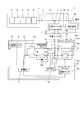
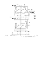
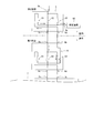
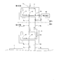
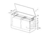
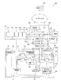
- FIG. 1st Embodiment of this invention It is a block diagram which shows the structure of the electric power generation system by 1st Embodiment of this invention. It is a figure for demonstrating the detailed structure (1st state and 4th state) of the changeover switch of the electric power generation system by 1st Embodiment shown in FIG. It is a figure for demonstrating the detailed structure (2nd state and 3rd state) of the changeover switch of the electric power generation system by 1st Embodiment shown in FIG. It is a figure for demonstrating the detailed structure (2nd state and 4th state) of the changeover switch of the electric power generation system by 1st Embodiment shown in FIG. It is a perspective view which shows the electrical storage unit of the electric power generation system by 1st Embodiment of this invention.
- the solar power generation system 1 is connected to a power generation output unit 2 that outputs power generated using sunlight and the power system 50 so that the power output by the power generation output unit 2 can be reversely flowed.
- Inverter 3 for output to power system 50 side, selector switch 5 and selector switch 6 connected to bus 4 connecting inverter 3 and power system 50, and power storage unit 7 connected to selector switch 6. Yes.
- the inverter 3 has a function of converting DC power output from the generated power output unit 2 into AC.
- the generated power output unit 2 is linked to the power system 50 via the inverter 3.
- a specific load 60 is connected to the changeover switch 5.
- the specific load 60 is a device driven by an AC power supply.
- the specific load 60 is desired to be always supplied with power from a power source, and includes a device that needs to operate constantly.
- the generated power output unit 2 includes a plurality of photovoltaic power generation modules 21 connected in series with each other.
- the photovoltaic power generation module 21 can be configured using various types of solar cells such as a thin film silicon system, a crystalline silicon system, or a compound semiconductor system.
- the solar power generation module 21 is an example of the “power generation module” in the present invention.
- the changeover switch 5 is connected to the bus 4 via the wiring 5a and is connected to the specific load 60 via the wiring 5b.
- the changeover switch 5 is connected to the changeover switch 6 via wirings 5c and 5d and wirings 6a and 6b.
- the change-over switch 5 includes three change-over switches 51, 52, and 53, and the three change-over switches 51 to 53 are simultaneously turned on / off by a user operation. That is, by the user's operation, the changeover switches 51, 52, and 53 are switched between the first state in which the changeover switches 51, 52, and 53 are off, and the second state in which the changeover switches 51, 52, and 53 are on, on, and off, respectively.
- the wiring 5a and the wiring 5b are connected via the switch 53 that is turned on, and the wiring 5a and the wiring 5c are disconnected by the switching switch 52 that is turned off. 5d and the wiring 5b are disconnected by the changeover switch 51 which is turned off.
- the bus 4 and the specific load 60 are connected without passing through the power storage unit 7.
- the bus 4 and the power storage unit 7 are electrically disconnected. Therefore, when the changeover switch 5 is in the first state, it is possible to supply power from the bus 4 to the specific load 60.
- the wiring 5a and the wiring 5b are disconnected by the change-over switch 53 that is turned off, and the wiring 5a and the wiring 5c are connected via the change-over switch 52 that is turned on.
- the wiring 5d and the wiring 5b are connected via a changeover switch 51 that is turned on.
- the changeover switch 5 and the changeover switch 6 are electrically connected. As a result, the connection destination of the bus 4 is switched according to switching of the selector switch 6 described later.
- the changeover switch 5 is provided in the switchboard 8 installed indoors.
- the specific load 60 and the inverter 3 are also installed indoors.
- An AC-DC converter 72 is electrically connected to the changeover switch 6 via a wiring 6 c and a wiring 7 a of the power storage unit 7.
- the changeover switch 6 is connected to the inverter 74 a in the power storage unit 7 via the wiring 6 d and the wiring 7 b of the power storage unit 7.
- the changeover switch 6 is also changed by the user's manual operation, similarly to the changeover switch 5.
- the change-over switch 6 includes three change-over switches 61, 62, and 63, and the three change-over switches 61 to 63 are simultaneously turned on / off by a user operation. That is, by the user's operation, the changeover switches 61, 62, and 63 are respectively switched between the third state in which the changeover switches 61, 62, and 63 are off, and the fourth state in which the changeover switches 61, 62, and 63 are respectively on, on, and off.
- the wiring 6a and the wiring 6b are connected via the switch 63 that is turned on, and the wiring 6a and the wiring 6c are disconnected by the switch 62 that is turned off.
- the wiring 6b is disconnected by the switch 61 which is turned off. Since the electrical connection between the changeover switch 6 and the power storage unit 7 is disconnected, the bus 4 and the power storage unit 7 are electrically disconnected.
- the wiring 6a and the wiring 6b are disconnected by the switch 63 which is turned off, and the wiring 6a and the wiring 6c are connected via the switch 62 which is turned on.
- the wiring 6d and the wiring 6b are connected via a switch 61 that is turned on. Since the changeover switch 6 and the power storage unit 7 are electrically connected, the bus bar 4 and the power storage unit 7 are electrically connected via the changeover switch 5 in the second state.
- the changeover switch 5 and the changeover switch 6 can switch the current path independently of each other.
- the changeover switch 5 is switched to the first state with the power storage unit 7 removed, either the power system 50 or the generated power output unit 2 is connected to the specific load 60 via the current path passing through the wires 5a and 5b. Power is supplied directly to the specific load 60 from both.
- the bus 4 and the power storage unit 7 are electrically connected via the changeover switch 5 and the changeover switch 6.
- the bus 4 and the power storage unit 71 of the power storage unit 7 are connected, and the power storage unit 71 and the specific load 60 are connected.
- the power from the power system 50 or the generated power output unit 2 can be stored in the power storage unit 71, and the power from the power storage unit 71 can be supplied to the specific load 60.
- the power from the power system 50 or the generated power output unit 2 is not supplied to the power storage unit 71, and the power is supplied to the specific load 60. It is also possible to supply
- the power storage unit 7 includes a power storage unit 71 that stores power from the power system 50, an AC-DC converter 72 that converts power from alternating current to direct current, and a charge / discharge control box 73 that controls charging / discharging of the power storage unit 71.
- the power storage unit 7 and the control box 75 provided in the power storage unit 7 constitute a charge / discharge system of the solar power generation system 1.
- the electrical storage unit 7 is comprised so that it may function as a charging / discharging system of the solar power generation system 1 with the apparatus accommodated in the inside of the housing
- the AC-DC converter 72, the charge / discharge control box 73, the inverter unit 74, and the control box 75 are examples of the “storage unit device” of the present invention, and the AC-DC converter 72 is the “converter” of the present invention. It is an example.
- the control box 75 is an example of the “control unit” in the present invention.
- the power storage unit 7 is installed outdoors.
- the power storage unit 7 includes a wiring 7 a for receiving power from the power system 50 and a wiring 7 b for supplying power to the specific load 60.
- the power from the power system 50 and / or the generated power output unit 2 is stored in the power storage unit 71.
- a power generation system capable of supplying the stored power to the specific load 60 is configured.
- a secondary battery for example, a lithium ion storage battery that has a low spontaneous discharge and a high charge / discharge efficiency is used.
- the lithium ion storage battery has a characteristic of absorbing heat during storage.
- the charge / discharge control box 73 includes three switches 73 a, 73 b and 73 c that can be switched on / off by the control box 75.
- Switches 73 a and 73 b are connected in series in a charging path between AC-DC converter 72 and power storage unit 71.
- a diode 73d that rectifies current in a direction from the AC-DC converter 72 toward the power storage unit 71 is provided on a bypass path provided in parallel with the switch 73a.
- the switch 73 c is provided in the discharge path between the power storage unit 71 and the inverter unit 74.
- the switch 73b When charging the power storage unit 71 from one or both of the power system 50 and the generated power output unit 2, the switch 73b is first turned on, and then the switch 73a is turned on. As a result, the reverse flow from the power storage unit 71 to the AC-DC converter 72, which occurs when the AC-DC converter 72 is just started and its output voltage is low, can be prevented by the diode 73d.
- the switch 73c when discharging from the power storage unit 71 to the specific load 60 via the inverter unit 74, the switch 73c is turned on. Further, the switch 73a is turned off, and then the switch 73b is turned off. In this case as well, backflow from the power storage unit 71 to the AC-DC converter 72 can be prevented by the diode 73d. When all of switches 73a, 73b, and 73c are turned on, both charging and discharging of power storage unit 71 can be performed.
- the inverter unit 74 includes an inverter 74a as a DC-AC converter for supplying power of the power storage unit 71 that outputs DC power to a specific load 60 driven by an AC power source, and a switch that can be switched on / off 74b.
- the switch 74b is provided between the wiring 7a and the wiring 7b.
- the switch 74b is normally turned on, and the inverter 74a turns off the switch 74b when power is supplied to the inverter 74a, preferably when power of a predetermined voltage or higher is supplied to the inverter 74a. It is configured as follows.
- a switch 77 that can be switched on / off is provided in a portion closer to the AC-DC converter 72 than the contact with the switch 74b. ing.
- the switch 77 is configured to be turned on / off according to the temperature of a temperature sensor 75a provided in the control box 75. That is, when the temperature of the temperature sensor 75a is equal to or lower than a predetermined temperature (for example, about 70 degrees), the switch 77 is turned on and power from the bus 4 side is supplied to the AC-DC converter 72. When the temperature of the temperature sensor 75a exceeds a predetermined temperature, the switch 77 is turned off, and the electrical connection between the bus 4 side and the AC-DC converter 72 is disconnected. On / off of the switch 77 is controlled by the control box 75.
- the temperature sensor 75a is an example of the “first temperature detector” in the present invention.
- 70 ° C. is an example of the “first threshold value” in the present invention.
- the control box 75 Since the power of the control box 75 is taken from the wiring between the switch 77 and the AC-DC converter 72, when the switch 77 is turned off, the control box 75 is also driven by the power supply being lost. It is configured to stop automatically. When the control box 75 is stopped, the output from the AC-DC converter 72 is turned off (the power supply to the AC-DC converter 72 is also cut off), and the switches 73a and 73c are turned off. When the switch 73c is turned off, the power supply to the inverter 74a is cut off. Since the power supply to the inverter 74a is cut off, the switch 74b is turned on as described above.
- the switch 74b By turning on the switch 74b, when the changeover switch 5 and the changeover switch 6 are in the second state and the fourth state, respectively, from the bus 4 side through the current path through the wiring 7a, the switch 74b, and the wiring 7b. Can be supplied to the specific load 60 without going through the power storage unit 71.
- the current path through the wiring 7a, the switch 74b, and the wiring 7b is an example of the “second power supply path” in the present invention.
- the switch 74b and the switch 77 are turned off and on, respectively, and the inside of the casing 76 (particularly, the AC-DC converter 72) is in an abnormal heat generation state (for example, When the temperature inside the control box 75 reaches about 70 ° C. or higher), the switch 74b and the switch 77 are turned on and off, respectively.
- an abnormal heat generation state occurs, the AC-DC converter 72, the power storage unit 71, the inverter 74a, and the control box 75, which are heat sources, are maintained while maintaining the power supply from the bus 4 side to the specific load 60. It is possible to stop. For this reason, when the inside of the casing 76 (particularly, the AC-DC converter 72) is in an abnormal heat generation state, a further increase in temperature can be suppressed. Damage can be reduced.
- a temperature sensor 78 and an exhaust fan 79 are further provided in the housing 76.
- the exhaust fan 79 is driven, so that the heat inside the housing 76 can be discharged.
- the temperature sensor 78 and the exhaust fan 79 are not connected to other devices (such as the power storage unit 71 and the control box 75) in the casing 76, and the power source is driven from the wiring 7a. Therefore, the temperature sensor 78 and the exhaust fan 79 operate independently from other devices (such as the power storage unit 71 and the control box 75) in the housing 76 even when the switch 77 is turned off. Configured to do.
- the temperature sensor 78 and the exhaust fan 79 are examples of the “second temperature detection unit” and the “exhaust unit” of the present invention, respectively. Further, 40 ° C. is an example of the “second threshold value” in the present invention.
- control box 75 is configured to output the AC-DC converter 72, the charge / discharge control box based on the charge amount of the power storage unit 71, the detection result of the temperature sensor 75a, the current time (whether or not it is the midnight time zone), and the like.
- 73 has a function of controlling on / off of the switches 73a to 73c of the switch 73, the switch 74b of the inverter unit 74, the switch 77, and the like.
- the temperature inside the casing 76 (in particular, the AC-DC converter 72) is a predetermined temperature (for example, the temperature inside the control box 75). Is about 70 ° C.
- each switch such as the charge / discharge control box 73, the AC-DC converter 72, and the switch 74b of the inverter unit 74 is controlled based on a predetermined program. .
- the control box 75 charges the power storage unit 71 from the power system 50 during normal operation, for example, at midnight, and when it is necessary to supply power to the specific load 60, the control box 75 sends the specific load 60 from the power storage unit 71 regardless of day or night.
- Each switch is controlled so as to supply power.
- a current path for charging the power storage unit 71 by supplying power from the bus 4 side to the power storage unit 71 is a path passing through the wiring 7a, the switch 77, the AC-DC converter 72, the switch 73a, and the switch 73b.
- the current path when the power storage unit 71 discharges and supplies power to the specific load 60 is a path that passes through the switch 73c, the inverter 74a, and the wiring 7b.
- the power stored in the power storage unit 71 is not supplied to the power system 50.
- the path passing through the switch 73c, the inverter 74a, and the wiring 7b is an example of the “first power supply path” in the present invention.
- the control box 75 even when the control box 75 discharges the power storage unit 71 during normal operation, the capacity of the power storage unit 71 does not fall below a predetermined threshold (for example, 50% of the fully charged state). In this way, the discharge of the power storage unit 71 is controlled.
- the control box 75 determines that the capacity of the power storage unit 71 has become equal to or less than the threshold value, the control box 75 stops supplying power from the power storage unit 71 to the specific load 60 and directly supplies power to the specific load 60 from the bus 4.
- each switch to supply. Specifically, the switch 73c of the charge / discharge control box 73 is turned off and the switch 74b of the inverter unit 74 is turned on. At this time, the output of the AC-DC converter 72 is turned off, and power charging is not performed during the daytime. However, if it exceeds the allowable voltage of the distribution line due to the reverse power flow from the customer side, or if it falls on a specific day when the power demand is expected to be significantly lower than the power generation, go to the power storage unit 71 The AC-DC converter 72 and each switch are controlled so as to be charged.
- the supply of power from the power system 50 is stopped, so that the control box 75 is stopped. Further, the switch 77 and the switches 73a and 73b are turned off. As a result, no power is supplied to the AC-DC converter 72, and the driving of the AC-DC converter 72 is also stopped. Further, the voltage line signal of the wiring 7a is input to the switch 73c. When a power failure occurs, the switch 73c is turned on by detecting that no voltage is applied to the wiring 7a. . In addition, the inverter 74 a is configured to operate by power supply from the power storage unit 71.
- the discharge is controlled so that the remaining capacity of the power storage unit 71 does not fall below a predetermined threshold (for example, 50%) during normal operation.
- a predetermined threshold for example, 50%
- the control box 75 is charged and discharged so as to discharge even when the amount of power stored in the power storage unit 71 falls below a predetermined threshold (50% of the fully charged state).
- 73 is controlled. In an emergency, the power supply to the control box 75 is cut off, and the switch 73c cannot be turned on / off during the operation.
- a lithium ion storage battery is used to store power. Electric power can be used effectively.
- the power storage unit 7 includes a box-shaped casing 76 and five box-shaped lithium ion storage batteries 711, a box-shaped charge / discharge control box 73, A box-shaped control box 75 and a box-shaped power conversion unit 700 in which the inverter unit 74 and the AC-DC converter 72 are integrally configured are accommodated.
- the lithium ion storage battery 711 is a pack-shaped storage battery unit in which a large number of lithium ion storage battery cells are arranged.
- a power storage unit 71 is composed of five lithium ion storage batteries 711.
- These eight devices are arranged side by side so as to be adjacent in the horizontal direction.
- the control box 75 and the power conversion unit 700 are adjacent to each other. That is, the temperature sensor 75a of the control box 75 is disposed in the vicinity of the power conversion unit 700 (particularly, the AC-DC converter 72).
- the inverter unit 74 is arranged on the control box 75 side. That is, the AC-DC converter 72 is disposed at a position separated from the control box 75 via the inverter unit 74.
- the power conversion unit 700 and the control box 75 are examples of the “first housing portion” and the “second housing portion” in the present invention.
- the temperature sensor 75a of the control box 75 is arranged on the inverter unit 74 side.
- the exhaust fan 79 is provided on the side surface of the upper portion of the housing 76, and the temperature sensor 78 is disposed at a position adjacent to the exhaust fan 79 on the upper portion of the housing 76.
- an air inlet 76 a is formed in the upper portion of the housing 76.
- the intake port 76a is formed on a side surface facing the side surface of the casing 76 in which the exhaust fan 79 and the temperature sensor 78 are arranged. That is, the temperature sensor 78 is disposed at a position separated from the intake port 76a, and the temperature sensor 78 is disposed at a position closer to the exhaust fan 79 than the intake port 76a.
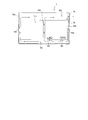
- Two heat dissipating fans 701 for discharging heat generated by driving the AC-DC converter 72 and the inverter 74a from the power conversion unit 700 are integrally provided at the lower part of the power conversion unit 700.
- the heat radiating fan 701 is disposed so as to blow downward from the lower surface of the power conversion unit 700 toward the lower side of the housing 76.
- the heat radiating fan 701 is an example of the “blower” in the present invention.
- an air flow path 761 is provided between the inner bottom surface of the casing 76 and each device (the lithium ion storage battery 711, the charge / discharge control box 73, the control box 75, the power conversion unit 700, etc.). Further, between the inner surface of the housing 76 and each device, and between each device (center portion in the housing 76), the air flow path 761 communicates and extends vertically to the exhaust fan 79. An air flow path 762 is provided. As a result, the air containing the heat sent by the heat radiating fan 701 flows through the case 76 through the air flow path 761 at the bottom of the case 76.
- the air sent by the heat radiating fan 701 passes along the air flow path 762, rises along the side surface of each device, and is sent to the exhaust fan 79 at the top of the housing 76.
- the local heat in the casing 76 is effectively diffused by the heat radiating fan 701, and is efficiently discharged by the exhaust fan 79 through the air circulation path 762.
- the air circulation path 762 is an example of the “venting path” in the present invention.
- the power storage unit 7 is configured such that the lithium ion storage battery 711 is heated using heat discharged from the power conversion unit 700 into the housing 76. Further, in order to suppress the temperature inside the casing 76 from excessively rising due to the heat released from the power conversion unit 700 or direct sunlight, the heat stored inside the casing 76 is the temperature inside the casing 76. When the temperature detected by the temperature sensor 78 is higher than a predetermined temperature (about 40 ° C.), the exhaust fan 79 exhausts the air from the upper portion of the housing 76.
- Each lithium ion storage battery 711, charge / discharge control box 73, and power conversion unit 700 is provided with a communication unit (not shown) for communicating the state of each device (for example, temperature state) to the control box 75. It has been.
- the communication units of each lithium ion storage battery 711 are connected in series in a daisy chain, and are configured so that five lithium ion storage batteries 711 are handled as a unit.
- the temperature sensor 75a for detecting the temperature inside the casing 76
- the temperature in the casing 76 increases
- casing 76 can be started rapidly.
- the temperature rise of the power storage unit 71 can be suppressed, so that the function of the power storage unit 71 can be suppressed from being lowered.
- the driving of the AC-DC converter 72 is stopped, so that the temperature inside the casing 76 is reduced.
- the temperature rises to 70 ° C. or higher it is possible to stop driving the AC-DC converter 72 that generates the largest amount of heat among the devices stored in the case 76, so that the temperature in the case 76 is excessive. The rise can be effectively suppressed.
- the driving of the AC-DC converter 72 is stopped and the AC-DC converter 72 of the power storage unit 71 is stopped.
- the drive for performing the charging operation via the switch and the discharging operation via the path passing through the switch 73c, the inverter 74a and the wiring 7b is stopped.
- the driving of the device for performing the discharging operation is stopped, the driving of the power storage unit 71 itself can also be stopped. As a result, charging / discharging at a high temperature is suppressed, and deterioration of the power storage unit 71 is suppressed. can do.
- the current path through the wiring 7a, the switch 74b, and the wiring 7b in the devices of the power storage unit 7 The driving of at least one device other than the upper device is stopped.
- the driving of devices such as the AC-DC converter 72 serving as a heat source is stopped to suppress the generation of heat, and the wiring 7a from the power storage unit 71, the switch 74b, and the wiring 7b are connected.
- the power supply to a predetermined load via the current path can be continued.
- the exhaust fan 79 is driven when it is determined based on the detection result of the temperature sensor 78 that the temperature inside the housing 76 has become a predetermined 40 ° C. lower than 70 ° C. With this configuration, exhaust by the exhaust fan 79 is started when the internal temperature of the casing 76 reaches a predetermined 40 ° C. lower than 70 ° C. Therefore, the temperature inside the casing 76 is 70 ° C. It is possible to suppress the rise to ° C.
- the temperature sensor 78 that is housed in the housing 76 and disposed on the top of the housing 76, the heat in the housing 76 moves upward, so the temperature sensor 78 disposed on the top of the housing 76. Thus, the temperature rise in the casing 76 can be detected quickly.
- an exhaust fan 79 that operates to exhaust the air inside the casing 76 to the outside based on the detection result of the temperature sensor 78, it is automatically performed when the temperature inside the casing 76 rises.
- the heat in the housing 76 can be exhausted by the exhaust fan 79, an increase in the temperature in the housing 76 can be effectively suppressed.
- the temperature inside the casing 76 is lowered by the outside air, and the exhaust fan 79.
- the temperature sensor 78 can be separated from the vicinity of the intake port 76a where the temperature decreases the fastest when exhausting is performed. As a result, the temperature in the casing 76 can be accurately detected by the temperature sensor 78, so that the exhaust by the exhaust fan 79 is stopped in a state where the temperature in the casing 76 is not actually lowered sufficiently. Can be suppressed.
- the capacity of the power storage unit 71 when the capacity of the power storage unit 71 is 7.85 kWh, the output of the AC / DC converter 72 is 1.5 kW, and the power storage unit 71 is charged from a state where the power storage amount is 0 to a fully charged state, It is designed to charge over half of the time zone (for example, 8 hours from 23:00 to 7:00). In this case, the charging time is 5 hours or more by simple calculation. In the lithium ion storage battery, since it is necessary to control the charging speed to be slow in the vicinity of full charge, the actual charging time is further increased.
- the capacity of the power storage unit 71 is also required to be about 3 kWh or more. Control is performed to stop discharging at 50% of the capacity of the power storage unit 71, and a capacity of about 6 kWh or more is required to continue driving the specific load 60 at a power failure of 5 hours with a capacity of 50% of full charge. Become. The value of 7.85 kWh is a value determined with a margin for this 6 kWh.
- the specific load 60 has a power consumption that is less than the storage capacity of the day and that can be driven for, for example, 5 hours or more by the stored power of the power storage unit 71.
- the specific load 60 is not used, it is difficult to set the load amount, and it is also difficult to set an appropriate capacity of the power storage unit 71.
- the rated power of the inverter 74a is 1 kW, and the power consumption of the specific load 60 is about 1 kW at the maximum.
- the volume energy density of the lead storage battery is about 50 Wh / L to 100 Wh / L, and the volume energy density of the lithium ion storage battery is about 400 Wh / L to 600 Wh / L. Therefore, when the volume energy densities of the lead storage battery and the lithium ion storage battery are 100 Wh / L and 500 Wh / L, respectively, a difference of 5 times occurs. That is, when storing the storage battery in the casing 76, the lead storage battery requires a casing 76 having a volume approximately five times that of the lithium ion storage battery. Further, the surface area of the casing 76 in this case has a difference of about twice.
- the amount of heat required to raise the inside of the casing 76 by the same temperature is the volume ratio of the casing 76 (about 5 times). And from the surface area ratio (about 2 times) there is a difference of about 10 times.
- the heat generation amount of the AC-DC converter 72 serving as a heat generation source is proportional to the output value of the AC-DC converter 72, and the output value of the AC-DC converter 72 is the capacity of the storage battery 71 as described above. Therefore, if the storage battery capacity is the same, the calorific value is the same. Therefore, regarding the temperature rise effect in the casing 76 due to the heat generated by the AC-DC converter 72, the lead storage battery is about one-tenth of the lithium ion storage battery.
- the temperature in the housing 76 is easily increased by heat discharged from a device such as the AC-DC converter 72 than when a lead storage battery is used. Since it rises, temperature detection by the temperature sensors 75a and 78 is more important.
- the generated power output unit 101 connects the plurality of solar power generation modules 21a connected to each other and the generated power of the solar power generation module 21a to the inverter 3 side or the power storage unit 71 side of the power storage unit 7 in a switchable manner. Switching circuit unit 101a.
- the switching circuit unit 101a When the generated power output unit 101 is connected to the inverter 3 side, the switching circuit unit 101a electrically disconnects the generated power output unit 101 and the power storage unit 71 and connects the generated power output unit 101 to the power storage unit 71. When connecting to the side, the connection between the generated power output unit 101 and the inverter 3 is electrically disconnected. Further, when the switching circuit unit 101a connects the generated power output unit 101 to the inverter 3 side, the connection state of the five solar power generation modules 21a is connected to each other in series with the five solar power generation modules 21a. It is possible to switch to a serial connection state.
- the switching circuit unit 101a connects the generated power output unit 101 to the power storage unit 71 side, the five solar power generation modules 21a are connected in parallel to each other in the connection state of the five solar power generation modules 21a. It is possible to switch to a parallel connection state.
- the control unit 102 transmits a control command to the control box 75 of the power storage unit 7 based on the power generation amount of the generated power output unit 101, the charge amount of the power storage unit 71, the operation status of the inverter 3, preset setting information, and the like. In addition, it has a function of receiving information related to the power storage unit 7 such as the amount of power stored in the power storage unit 71 from the control box 75. Further, the control unit 102 switches the switching circuit unit 101a of the generated power output unit 101 based on the power generation amount of the generated power output unit 101, the charge amount of the power storage unit 71, the operation status of the inverter 3, preset setting information, and the like. And the like.
- control unit 102 determines whether the system is in normal operation or in an emergency based on the amount of charge in power storage unit 71, the operating status of inverter 3, and preset setting information. .
- the power storage unit 7 and the control box 75 constitute a charge / discharge system of the solar power generation system 1, and the power storage unit 7 and the control unit 102 also constitute a charge / discharge system of the solar power generation system 1. Yes.
- control unit 102 When the control unit 102 determines that it is during normal operation, the control unit 102 switches the connection state of the photovoltaic power generation module 21a to the serial connection state and switches the connection destination of the generated power output unit 101 to the inverter 3 side.
- the circuit unit 101a is controlled. During normal operation, the output power of the generated power output unit 101 is consumed by the specific load 60 or the like, and the surplus power is reversely flowed to the power system 50.
- control unit 102 changes the connection state of the photovoltaic power generation module 21a to the parallel connection state and switches the connection destination of the generated power output unit 101 to the power storage unit 71 side.
- the switching circuit unit 101a is controlled.
- the output power of the generated power output unit 101 is supplied to the power storage unit 71, and the specific load 60 is driven by the charging power of the power storage unit 71 and the output power of the generated power output unit 101.
- control unit 102 generates solar power based on the detection results of the current detection unit 103 provided on the generated power output unit 101 side of the inverter 3 and the current detection unit 104 provided on the power system 50 side of the inverter 3. It is possible to detect the amount of power generated by the module 21a, the amount of reverse power flow, the amount of power consumed by the specific load 60, and the like. In addition, the control unit 102 controls the power generation amount of the solar power generation module 21a, the reverse power flow amount, the power consumption at the specific load 60, the state of the power storage unit 71 (charge amount, temperature state, etc.), and other solar power generation systems 100. This information is transmitted to the external server 150 via the Internet.
- This external server 150 is a server of a maintenance company of the photovoltaic power generation system 100, for example. Thereby, the maintenance company can grasp the state of the photovoltaic power generation system 100 at any time.
- the external server 150 can be accessed from the user's PC (personal computer) 160 or the like via the Internet, and the user can check the state of the solar power generation system 100 using the PC 160. Is possible.
- the specific load 60 can be driven for a longer time.
- the present invention is not limited thereto, and other DC power generation devices or wind power generation devices may be used as power generation modules.
- a power generation module that generates power using natural energy of may be used.
- the lithium ion storage battery 711 is used as the power storage unit 71 .
- the present invention is not limited to this, and other secondary batteries may be used.
- a storage battery such as a nickel hydride storage battery or a lead storage battery may be used.
- a capacitor may be used instead of the storage battery.
- the device driven by the AC power source is shown as an example of the specific load 60, but a device driven by the DC power source may be used.
- a DC-DC converter that performs voltage conversion between direct current and direct current is used between the power storage unit 71 and the specific load 60 in place of the inverter 74a that converts direct current to alternating current.
- the power storage unit 71 and the specific load 60 are directly connected.
- a DC load and an AC load may be mixed.
- the temperature sensor 78 and the exhaust fan 79 are provided in the power storage unit 7.
- the present invention is not limited to this, and the temperature sensor 78 and the exhaust fan 79 are not provided. Also good.
- the present invention is not limited to this, and the arrangement is appropriately changed. May be.
- the AC-DC converter 72 and the inverter unit 74 may be separated, and the control box 75 having the temperature sensor 75 a may be disposed between the AC-DC converter 72 and the inverter unit 74.
- the present invention is not limited to this, and the power storage unit 7 may be installed indoors.
- the example in which the temperature sensor 75a as the “first temperature detection unit” is provided in the control unit 75 has been described.
- the present invention is not limited to this, and the control unit 75 It may be provided outside.
- the “first threshold value” and the “second threshold value” are 70 ° C. and 40 ° C., respectively.
- the present invention is not limited thereto, and 70 ° C. and 40 ° C. It may be a temperature other than ° C.
- the temperature is 70 ° C. or higher in a configuration in which no device is provided on the current path (second power supply path) via the wiring 7a, the switch 74b, and the wiring 7b.
- the present invention is not limited to this. That is, in a configuration in which devices are provided on the second power supply path, devices other than the devices on the second power supply path may be stopped when the temperature reaches 70 ° C. or higher. Thereby, even when a device such as the AC-DC converter 72 is stopped, it is possible to continue supplying power to the load via the second power supply path.
Landscapes
- Engineering & Computer Science (AREA)
- Chemical Kinetics & Catalysis (AREA)
- Electrochemistry (AREA)
- General Chemical & Material Sciences (AREA)
- Chemical & Material Sciences (AREA)
- Manufacturing & Machinery (AREA)
- Microelectronics & Electronic Packaging (AREA)
- Physics & Mathematics (AREA)
- Thermal Sciences (AREA)
- Power Engineering (AREA)
- Secondary Cells (AREA)
- Charge And Discharge Circuits For Batteries Or The Like (AREA)
- Battery Mounting, Suspending (AREA)
- Supply And Distribution Of Alternating Current (AREA)
Abstract
Description
まず、図1~図7を参照して、本発明の第1実施形態による発電システム(太陽光発電システム1)の構造を説明する。
次に、図8を参照して、本発明の第2実施形態による発電システム(太陽光発電システム100)について説明する。この第2実施形態では、上記第1実施形態と異なり、太陽光発電モジュール21aによる発電電力を蓄電部71に直接供給する構成の例について説明する。
Claims (16)
- 電力を蓄電する蓄電部と、
電力を変換するコンバータと、
前記コンバータの近傍に配置された第1温度検知部と、
少なくとも前記コンバータ、前記第1温度検知部および前記蓄電部を収納する筐体とを備える、蓄電ユニット。 - 前記筐体に収納され、前記コンバータを制御する制御部をさらに備え、
前記制御部は、前記第1温度検知部による検知温度が所定の第1閾値以上になったと判断した場合に、前記コンバータの駆動を停止する、請求項1に記載の蓄電ユニット。 - 前記筐体に収納されるインバータをさらに備え、
前記制御部は、前記第1温度検知部による検知温度が前記第1閾値以上になったと判断した場合に、前記コンバータおよび前記インバータの駆動を停止する、請求項2に記載の蓄電ユニット。 - 前記蓄電部から所定の負荷に電力を供給する第1電力供給経路をさらに備え、
前記制御部は、前記第1温度検知部による検知温度が前記第1閾値以上になったと判断した場合に、前記コンバータの駆動を停止するとともに、前記蓄電部の前記コンバータを介した充電動作と前記第1電力供給経路を介した放電動作とを行うための機器の駆動を停止する、請求項2に記載の蓄電ユニット。 - 電力系統から前記蓄電部を介さずに所定の負荷に電力を供給する第2電力供給経路をさらに備え、
前記制御部は、前記第1温度検知部による検知温度が前記第1閾値以上になったと判断した場合に、前記蓄電ユニットの機器のうちの前記第2電力供給経路上の機器以外の少なくとも1つの機器の駆動を停止する、請求項2に記載の蓄電ユニット。 - 前記筐体に収納され、前記筐体の内部の温度を検知するための第2温度検知部と、
前記筐体の内部の空気を外部へ排気するための排気部とをさらに備え、
前記制御部は、前記第2温度検知部による検知温度が前記第1閾値よりも低い所定の第2閾値以上になったと判断した場合に、前記排気部を駆動する、請求項2に記載の蓄電ユニット。 - 前記排気部は、前記コンバータの駆動が停止された場合にも、独立して動作を行うように構成されている、請求項6に記載の蓄電ユニット。
- 前記筐体に収納されるとともに前記筐体の上部に配置され、前記筐体の内部の温度を検知するための第2温度検知部をさらに備える、請求項1に記載の蓄電ユニット。
- 前記第2温度検知部の検知結果に基づいて、前記筐体の内部の空気を外部へ排気するように動作する排気部をさらに備える、請求項8に記載の蓄電ユニット。
- 前記筐体は、外部の空気を取り入れる吸気口をさらに備え、
前記第2温度検知部と前記排気部との間の距離は、前記第2温度検知部と前記吸気口との間の距離よりも短い、請求項9に記載の蓄電ユニット。 - 前記吸気口は、前記筐体内において、前記排気部が設けられた前記筐体の一方側面に対して対向する他方側面に設けられている、請求項10に記載の蓄電ユニット。
- 前記排気部は、前記筐体内において、前記筐体の上部に配置されている、請求項9に記載の蓄電ユニット。
- 前記筐体内には、前記筐体内に収納される機器の少なくともいずれかの側面を通過して、前記排気部へと接続される通気経路が設けられている、請求項9に記載の蓄電ユニット。
- 前記コンバータは、箱状の第1収容部内に収容され、
前記第1温度検知部は、箱状の第2収容部内に収容され、
前記第1収容部と前記第2収容部とは前記筐体内で隣接するように配置されている、請求項1に記載の蓄電ユニット。 - 電力系統に連系され、自然エネルギーを用いて発電する発電モジュールと、
電力を蓄電する蓄電部と、電力を変換するコンバータと、前記コンバータの近傍に配置された第1温度検知部と、少なくとも前記コンバータ、前記第1温度検知部および前記蓄電部を収納する筐体とを含む蓄電ユニットとを備える、発電システム。 - 電力を蓄電する蓄電部と、電力を変換するコンバータと、前記コンバータの近傍に配置された第1温度検知部と、少なくとも前記コンバータ、前記第1温度検知部および前記蓄電部を収納する筐体とを含む蓄電ユニットと、
前記蓄電ユニットに含まれるコンバータを制御する制御部とを備え、
前記制御部は、前記第1温度検知部による検知温度が所定の第1閾値以上になったと判断した場合に、前記コンバータの駆動を停止する、充放電システム。
Priority Applications (3)
| Application Number | Priority Date | Filing Date | Title |
|---|---|---|---|
| JP2011544283A JP5673551B2 (ja) | 2009-12-04 | 2010-12-02 | 蓄電ユニット、発電システムおよび充放電システム |
| CN2010900014673U CN202997003U (zh) | 2009-12-04 | 2010-12-02 | 蓄电单元、发电系统及充放电系统 |
| US13/486,176 US20120235631A1 (en) | 2009-12-04 | 2012-06-01 | Storage Unit, Power Generation System, and Charge/Discharge System |
Applications Claiming Priority (6)
| Application Number | Priority Date | Filing Date | Title |
|---|---|---|---|
| JP2009276103 | 2009-12-04 | ||
| JP2009-276103 | 2009-12-04 | ||
| JP2009276351 | 2009-12-04 | ||
| JP2009-276351 | 2009-12-04 | ||
| JP2009282588 | 2009-12-14 | ||
| JP2009-282588 | 2009-12-14 |
Related Child Applications (1)
| Application Number | Title | Priority Date | Filing Date |
|---|---|---|---|
| US13/486,176 Continuation US20120235631A1 (en) | 2009-12-04 | 2012-06-01 | Storage Unit, Power Generation System, and Charge/Discharge System |
Publications (1)
| Publication Number | Publication Date |
|---|---|
| WO2011068154A1 true WO2011068154A1 (ja) | 2011-06-09 |
Family
ID=44115000
Family Applications (1)
| Application Number | Title | Priority Date | Filing Date |
|---|---|---|---|
| PCT/JP2010/071563 Ceased WO2011068154A1 (ja) | 2009-12-04 | 2010-12-02 | 蓄電ユニット、発電システムおよび充放電システム |
Country Status (4)
| Country | Link |
|---|---|
| US (1) | US20120235631A1 (ja) |
| JP (1) | JP5673551B2 (ja) |
| CN (1) | CN202997003U (ja) |
| WO (1) | WO2011068154A1 (ja) |
Cited By (8)
| Publication number | Priority date | Publication date | Assignee | Title |
|---|---|---|---|---|
| WO2013076956A1 (ja) * | 2011-11-21 | 2013-05-30 | パナソニック株式会社 | 電力供給システム |
| JP2013191772A (ja) * | 2012-03-14 | 2013-09-26 | Omron Corp | 電気機器、プログラム、およびファン制御方法 |
| JP2013240156A (ja) * | 2012-05-14 | 2013-11-28 | Mk Seiko Co Ltd | 電源装置 |
| JP2014063577A (ja) * | 2012-09-20 | 2014-04-10 | Kansai Electric Power Co Inc:The | 二次電池の冷却方法 |
| JP2014137979A (ja) * | 2013-01-18 | 2014-07-28 | Mitsubishi Heavy Ind Ltd | 二次電池システムの制御装置及び方法、それを備えた二次電池システム |
| WO2014122690A1 (ja) * | 2013-02-07 | 2014-08-14 | 三洋電機株式会社 | 蓄電システム |
| WO2015115087A1 (ja) * | 2014-01-31 | 2015-08-06 | 三洋電機株式会社 | 蓄電システム |
| JP2017199413A (ja) * | 2013-07-29 | 2017-11-02 | 京セラ株式会社 | 電力変換装置、電力変換装置の制御方法、及び電力変換システム |
Families Citing this family (18)
| Publication number | Priority date | Publication date | Assignee | Title |
|---|---|---|---|---|
| EP2454796A4 (en) | 2009-07-16 | 2017-11-22 | General Cybernation Group, Inc. | Smart and scalable power inverters |
| JP5786568B2 (ja) * | 2011-09-01 | 2015-09-30 | ソニー株式会社 | 蓄電装置および蓄電システム |
| CN103036288B (zh) * | 2012-12-10 | 2015-03-11 | 上海空间电源研究所 | 一种锂离子蓄电池补充充电控制系统 |
| US9240112B2 (en) * | 2013-03-15 | 2016-01-19 | Cyboenergy, Inc. | Online surveillance system to protect solar power plants |
| US20140268563A1 (en) * | 2013-03-15 | 2014-09-18 | Finsix Corporation | Method and apparatus for controlling heat in power conversion systems |
| CN105493645A (zh) | 2013-03-15 | 2016-04-13 | 芬斯克斯有限公司 | 用于控制电源转换系统中的热的方法和装置 |
| JP5447723B1 (ja) | 2013-07-19 | 2014-03-19 | パナソニック株式会社 | 充電器及び電子機器システム |
| JP5467553B1 (ja) * | 2013-10-24 | 2014-04-09 | パナソニック株式会社 | 充電器および電子機器システム |
| JP6183383B2 (ja) * | 2015-01-13 | 2017-08-23 | トヨタ自動車株式会社 | 車両 |
| JP6248962B2 (ja) | 2015-02-10 | 2017-12-20 | トヨタ自動車株式会社 | 車両の制動力発生装置 |
| US10477724B2 (en) * | 2015-03-09 | 2019-11-12 | Datalogic IP Tech, S.r.l. | Efficient heat exchange systems and methods |
| JP6728735B2 (ja) * | 2016-02-08 | 2020-07-22 | 株式会社ダイフク | 物品搬送設備 |
| US10236711B1 (en) * | 2016-03-28 | 2019-03-19 | Adam Brett Miller | Solar-charging storage container apparatus |
| IT201600121062A1 (it) * | 2016-11-29 | 2018-05-29 | Une Srl | Apparato di gestione di fonti di energia e di utenze collegate e metodo di gestione dell'apparato |
| WO2019059084A1 (ja) * | 2017-09-19 | 2019-03-28 | 日本電産株式会社 | 無人移動体 |
| JP7578016B2 (ja) * | 2021-02-16 | 2024-11-06 | トヨタ自動車株式会社 | 車載ソーラー充電制御システム、車載ソーラー充電制御方法及びプログラム |
| CN113949141B (zh) * | 2021-11-25 | 2022-09-09 | 深圳市宏成想科技有限公司 | 一种电池充放电控制器件 |
| US11621566B1 (en) * | 2022-10-05 | 2023-04-04 | 8Me Nova, Llc | Seasonal electrical resource allocation |
Citations (6)
| Publication number | Priority date | Publication date | Assignee | Title |
|---|---|---|---|---|
| JPH04293610A (ja) * | 1991-03-25 | 1992-10-19 | Suzuki Motor Corp | 車両用換気装置 |
| JPH04372537A (ja) * | 1991-06-21 | 1992-12-25 | Sanyo Electric Co Ltd | 複合入力装置 |
| JPH0983167A (ja) * | 1995-09-20 | 1997-03-28 | Fujitsu Ltd | 屋外設置電子装置筐体 |
| JPH0993834A (ja) * | 1995-09-26 | 1997-04-04 | Nippon Telegr & Teleph Corp <Ntt> | 無停電電源システム |
| JPH11178244A (ja) * | 1997-12-17 | 1999-07-02 | Hitachi Ltd | 無停電電源装置の切換スイッチの制御装置 |
| JP2002101570A (ja) * | 2000-09-20 | 2002-04-05 | Toshiba Battery Co Ltd | 電子機器装置 |
Family Cites Families (44)
| Publication number | Priority date | Publication date | Assignee | Title |
|---|---|---|---|---|
| US4229687A (en) * | 1979-05-07 | 1980-10-21 | Utah Research & Development Corporation | Temperature maintained battery system |
| DE3312810C2 (de) * | 1983-04-09 | 1986-06-19 | Danfoss A/S, Nordborg | Gerätekasten für eine Stromrichteranordnung |
| US4531511A (en) * | 1983-07-14 | 1985-07-30 | Hochberg Nelson D | Means for controlling heat flux |
| GB2153136B (en) * | 1984-01-20 | 1987-03-18 | Lilliwyte Sa | Temperature controlled na-s cell |
| US4926106A (en) * | 1986-07-22 | 1990-05-15 | Tanis Peter G | Aircraft battery charging device |
| US5185691A (en) * | 1991-03-15 | 1993-02-09 | Compaq Computer Corporation | Thermal packaging for natural convection cooled electronics |
| US5423045A (en) * | 1992-04-15 | 1995-06-06 | International Business Machines Corporation | System for distributed power management in portable computers |
| JP2928431B2 (ja) * | 1993-01-13 | 1999-08-03 | 富士通株式会社 | 補助バッテリ装置および充放電制御方法 |
| JP3157686B2 (ja) * | 1994-11-08 | 2001-04-16 | 松下電器産業株式会社 | 組電池の充電制御装置 |
| US5783872A (en) * | 1996-07-25 | 1998-07-21 | Northrop Grumman Corporation | Auxiliary battery voltage/temperature compensation for automotive 12 volt system for electric vehicles |
| US5793185A (en) * | 1997-06-10 | 1998-08-11 | Deltona Transformer Corporation | Jump starter |
| JPH11325557A (ja) * | 1998-05-15 | 1999-11-26 | Daikin Ind Ltd | 蓄電ユニット及び該蓄電ユニットを備えた蓄電式空気調和装置 |
| JP2001095179A (ja) * | 1999-09-17 | 2001-04-06 | Hitachi Ltd | 蓄電システム及び電力供給システム |
| US6700214B2 (en) * | 2000-02-14 | 2004-03-02 | Aura Systems, Inc. | Mobile power generation system |
| JP2001240323A (ja) * | 2000-02-28 | 2001-09-04 | Mitsubishi Electric Corp | エレベーターの制御装置 |
| JP3566252B2 (ja) * | 2001-12-12 | 2004-09-15 | 本田技研工業株式会社 | ハイブリット車両及びその制御方法 |
| JP2003259508A (ja) * | 2002-02-26 | 2003-09-12 | Sanyo Electric Co Ltd | 電気自動車用の電源装置 |
| TW553500U (en) * | 2002-04-24 | 2003-09-11 | Asia Pacific Fuel Cell Tech | Liquid cooling type fuel battery device |
| JP2003339118A (ja) * | 2002-05-22 | 2003-11-28 | My Way Giken Kk | 分散電源システム |
| JP4395316B2 (ja) * | 2003-04-16 | 2010-01-06 | パナソニックEvエナジー株式会社 | 電池パック |
| JP3801164B2 (ja) * | 2003-10-31 | 2006-07-26 | ソニー株式会社 | 電池パック |
| JP4427355B2 (ja) * | 2004-02-27 | 2010-03-03 | 三菱重工業株式会社 | 電力貯蔵システム |
| JP2005268258A (ja) * | 2004-03-16 | 2005-09-29 | Kyocera Corp | 電力変換装置 |
| JP4673019B2 (ja) * | 2004-09-10 | 2011-04-20 | 日立コンピュータ機器株式会社 | 情報処理装置 |
| US7245109B2 (en) * | 2005-11-30 | 2007-07-17 | Parailax Power Supply, Llc | Temperature sensitive power converter |
| JP4641507B2 (ja) * | 2006-03-17 | 2011-03-02 | シャープ株式会社 | 給電システム |
| ITMI20061296A1 (it) * | 2006-07-04 | 2008-01-05 | Campagnolo Srl | Metodo di controllo e sistema di carica di una unita' di alimentazione a batteria |
| US7808212B2 (en) * | 2006-07-24 | 2010-10-05 | Research In Motion Limited | Temperature-based charge and discharge control for a battery |
| JP4535039B2 (ja) * | 2006-07-25 | 2010-09-01 | トヨタ自動車株式会社 | 電源システムおよびそれを備えた車両、蓄電装置の昇温制御方法、ならびに蓄電装置の昇温制御をコンピュータに実行させるためのプログラムを記録したコンピュータ読取可能な記録媒体 |
| US20080084645A1 (en) * | 2006-10-04 | 2008-04-10 | Ahmad Nemer Jr | Emergency solar power supply |
| JP4600390B2 (ja) * | 2006-12-14 | 2010-12-15 | トヨタ自動車株式会社 | 電源システムおよびそれを備える車両、ならびにその制御方法 |
| US7656129B2 (en) * | 2007-01-30 | 2010-02-02 | Won-Door Corporation | Method and apparatus for battery-backed power supply and battery charging |
| JP5015649B2 (ja) * | 2007-04-13 | 2012-08-29 | 本田技研工業株式会社 | バッテリ及び電装機器の冷却構造 |
| US20080297136A1 (en) * | 2007-05-30 | 2008-12-04 | Ford Global Technologies, Llc | System and method to detect, in a vehicle, blockage of an airflow passage to a power storage unit |
| US8390248B2 (en) * | 2007-07-30 | 2013-03-05 | Kyocera Corporation | Electric power conversion apparatus and manufacturing method for the apparatus |
| DE102007050812A1 (de) * | 2007-10-24 | 2009-04-30 | Robert Bosch Gmbh | Elektrochemischer Energiespeicher |
| JP5081596B2 (ja) * | 2007-12-04 | 2012-11-28 | シャープ株式会社 | 電力供給システム |
| JP5018448B2 (ja) * | 2007-12-18 | 2012-09-05 | パナソニック株式会社 | 蓄電装置 |
| US9800074B2 (en) * | 2008-02-14 | 2017-10-24 | Fernando Emilio Adames | Portable battery charger |
| JP4911531B2 (ja) * | 2008-03-04 | 2012-04-04 | シャープ株式会社 | 電力変換装置およびそれを用いた発電システム |
| CN102165684B (zh) * | 2008-09-29 | 2014-02-12 | 丰田自动车株式会社 | 车辆的电源装置 |
| EP2330678B1 (en) * | 2008-09-30 | 2017-11-01 | NGK Insulators, Ltd. | Secondary battery power control method |
| JP2010119236A (ja) * | 2008-11-13 | 2010-05-27 | Kawamoto Pump Mfg Co Ltd | 太陽光発電電源装置 |
| US9960634B2 (en) * | 2010-12-10 | 2018-05-01 | Gem Corporation | Intelligent function installing power storage and generation package system |
-
2010
- 2010-12-02 JP JP2011544283A patent/JP5673551B2/ja not_active Expired - Fee Related
- 2010-12-02 WO PCT/JP2010/071563 patent/WO2011068154A1/ja not_active Ceased
- 2010-12-02 CN CN2010900014673U patent/CN202997003U/zh not_active Expired - Fee Related
-
2012
- 2012-06-01 US US13/486,176 patent/US20120235631A1/en not_active Abandoned
Patent Citations (6)
| Publication number | Priority date | Publication date | Assignee | Title |
|---|---|---|---|---|
| JPH04293610A (ja) * | 1991-03-25 | 1992-10-19 | Suzuki Motor Corp | 車両用換気装置 |
| JPH04372537A (ja) * | 1991-06-21 | 1992-12-25 | Sanyo Electric Co Ltd | 複合入力装置 |
| JPH0983167A (ja) * | 1995-09-20 | 1997-03-28 | Fujitsu Ltd | 屋外設置電子装置筐体 |
| JPH0993834A (ja) * | 1995-09-26 | 1997-04-04 | Nippon Telegr & Teleph Corp <Ntt> | 無停電電源システム |
| JPH11178244A (ja) * | 1997-12-17 | 1999-07-02 | Hitachi Ltd | 無停電電源装置の切換スイッチの制御装置 |
| JP2002101570A (ja) * | 2000-09-20 | 2002-04-05 | Toshiba Battery Co Ltd | 電子機器装置 |
Cited By (9)
| Publication number | Priority date | Publication date | Assignee | Title |
|---|---|---|---|---|
| WO2013076956A1 (ja) * | 2011-11-21 | 2013-05-30 | パナソニック株式会社 | 電力供給システム |
| JP2013191772A (ja) * | 2012-03-14 | 2013-09-26 | Omron Corp | 電気機器、プログラム、およびファン制御方法 |
| JP2013240156A (ja) * | 2012-05-14 | 2013-11-28 | Mk Seiko Co Ltd | 電源装置 |
| JP2014063577A (ja) * | 2012-09-20 | 2014-04-10 | Kansai Electric Power Co Inc:The | 二次電池の冷却方法 |
| JP2014137979A (ja) * | 2013-01-18 | 2014-07-28 | Mitsubishi Heavy Ind Ltd | 二次電池システムの制御装置及び方法、それを備えた二次電池システム |
| WO2014122690A1 (ja) * | 2013-02-07 | 2014-08-14 | 三洋電機株式会社 | 蓄電システム |
| JP2017199413A (ja) * | 2013-07-29 | 2017-11-02 | 京セラ株式会社 | 電力変換装置、電力変換装置の制御方法、及び電力変換システム |
| WO2015115087A1 (ja) * | 2014-01-31 | 2015-08-06 | 三洋電機株式会社 | 蓄電システム |
| JPWO2015115087A1 (ja) * | 2014-01-31 | 2017-03-23 | 三洋電機株式会社 | 蓄電システム |
Also Published As
| Publication number | Publication date |
|---|---|
| JPWO2011068154A1 (ja) | 2013-04-18 |
| CN202997003U (zh) | 2013-06-12 |
| US20120235631A1 (en) | 2012-09-20 |
| JP5673551B2 (ja) | 2015-02-18 |
Similar Documents
| Publication | Publication Date | Title |
|---|---|---|
| JP5673551B2 (ja) | 蓄電ユニット、発電システムおよび充放電システム | |
| JP5824614B2 (ja) | 充放電システム | |
| WO2011068151A1 (ja) | 蓄電ユニットおよび発電システム | |
| JP4367251B2 (ja) | 電源装置及び電子機器 | |
| US9124103B2 (en) | Electrical storage apparatus | |
| JP5660130B2 (ja) | 蓄電ユニット、蓄電池の容量値の補正方法および蓄電システム | |
| US20170331325A1 (en) | Modular microgrid unit and method of use | |
| KR102391119B1 (ko) | 배터리 냉각 시스템 및 그 제어 방법 | |
| WO2011068133A1 (ja) | 充放電システム、発電システムおよび充放電制御装置 | |
| CN102460890A (zh) | 电力设施互连系统 | |
| CN102906951A (zh) | 配电装置及使用该配电装置的配电系统 | |
| CN105375644A (zh) | 能量存储设备和包括该能量存储设备的能量存储系统 | |
| JP5975314B2 (ja) | 蓄電システム | |
| CN109845011B (zh) | 燃料电池系统和燃料电池系统的运行方法 | |
| KR102639780B1 (ko) | 에너지 저장장치 | |
| CN103367831A (zh) | 电池系统 | |
| CN117223133A (zh) | 具有冷却系统的电池动力设备 | |
| KR20230052034A (ko) | 에너지 저장장치 | |
| JP5857200B2 (ja) | コンテナ利用の独立電源装置 | |
| WO2014155410A1 (ja) | 蓄電池システム | |
| JP5903645B2 (ja) | 蓄電池管理システム | |
| JP6062699B2 (ja) | パワーコンディショナ及びこれを備える蓄電システム | |
| JP2015065770A (ja) | 蓄電システム | |
| WO2012133186A1 (ja) | スイッチ回路制御部及び充放電システム | |
| KR102847138B1 (ko) | 에너지 저장장치 |
Legal Events
| Date | Code | Title | Description |
|---|---|---|---|
| WWE | Wipo information: entry into national phase |
Ref document number: 201090001467.3 Country of ref document: CN |
|
| 121 | Ep: the epo has been informed by wipo that ep was designated in this application |
Ref document number: 10834604 Country of ref document: EP Kind code of ref document: A1 |
|
| WWE | Wipo information: entry into national phase |
Ref document number: 2011544283 Country of ref document: JP |
|
| NENP | Non-entry into the national phase |
Ref country code: DE |
|
| 122 | Ep: pct application non-entry in european phase |
Ref document number: 10834604 Country of ref document: EP Kind code of ref document: A1 |