WO2011068151A1 - 蓄電ユニットおよび発電システム - Google Patents
蓄電ユニットおよび発電システム Download PDFInfo
- Publication number
- WO2011068151A1 WO2011068151A1 PCT/JP2010/071558 JP2010071558W WO2011068151A1 WO 2011068151 A1 WO2011068151 A1 WO 2011068151A1 JP 2010071558 W JP2010071558 W JP 2010071558W WO 2011068151 A1 WO2011068151 A1 WO 2011068151A1
- Authority
- WO
- WIPO (PCT)
- Prior art keywords
- power
- storage unit
- housing
- power storage
- converter
- Prior art date
Links
- 238000010248 power generation Methods 0.000 title claims description 68
- HBBGRARXTFLTSG-UHFFFAOYSA-N Lithium ion Chemical compound [Li+] HBBGRARXTFLTSG-UHFFFAOYSA-N 0.000 claims description 49
- 229910001416 lithium ion Inorganic materials 0.000 claims description 49
- 238000006243 chemical reaction Methods 0.000 claims description 38
- 238000007599 discharging Methods 0.000 claims description 14
- 238000001514 detection method Methods 0.000 claims description 12
- 206010037660 Pyrexia Diseases 0.000 claims description 4
- 230000005611 electricity Effects 0.000 claims description 4
- 230000020169 heat generation Effects 0.000 description 9
- 230000007423 decrease Effects 0.000 description 6
- 230000002159 abnormal effect Effects 0.000 description 5
- 230000017525 heat dissipation Effects 0.000 description 5
- 230000000694 effects Effects 0.000 description 4
- 238000010438 heat treatment Methods 0.000 description 3
- 238000012986 modification Methods 0.000 description 3
- 230000004048 modification Effects 0.000 description 3
- 238000010586 diagram Methods 0.000 description 2
- 238000012423 maintenance Methods 0.000 description 2
- PXHVJJICTQNCMI-UHFFFAOYSA-N Nickel Chemical compound [Ni] PXHVJJICTQNCMI-UHFFFAOYSA-N 0.000 description 1
- XUIMIQQOPSSXEZ-UHFFFAOYSA-N Silicon Chemical compound [Si] XUIMIQQOPSSXEZ-UHFFFAOYSA-N 0.000 description 1
- 239000003990 capacitor Substances 0.000 description 1
- 150000001875 compounds Chemical class 0.000 description 1
- 229910021419 crystalline silicon Inorganic materials 0.000 description 1
- 229910000652 nickel hydride Inorganic materials 0.000 description 1
- 230000001151 other effect Effects 0.000 description 1
- 239000004065 semiconductor Substances 0.000 description 1
- 229910052710 silicon Inorganic materials 0.000 description 1
- 239000010703 silicon Substances 0.000 description 1
- 230000002269 spontaneous effect Effects 0.000 description 1
- 230000003685 thermal hair damage Effects 0.000 description 1
- 239000010409 thin film Substances 0.000 description 1
Images


Classifications
-
- H—ELECTRICITY
- H02—GENERATION; CONVERSION OR DISTRIBUTION OF ELECTRIC POWER
- H02J—CIRCUIT ARRANGEMENTS OR SYSTEMS FOR SUPPLYING OR DISTRIBUTING ELECTRIC POWER; SYSTEMS FOR STORING ELECTRIC ENERGY
- H02J3/00—Circuit arrangements for AC mains or AC distribution networks
- H02J3/28—Arrangements for balancing of the load in a network by storage of energy
- H02J3/32—Arrangements for balancing of the load in a network by storage of energy using batteries with converting means
-
- H—ELECTRICITY
- H01—ELECTRIC ELEMENTS
- H01M—PROCESSES OR MEANS, e.g. BATTERIES, FOR THE DIRECT CONVERSION OF CHEMICAL ENERGY INTO ELECTRICAL ENERGY
- H01M10/00—Secondary cells; Manufacture thereof
- H01M10/60—Heating or cooling; Temperature control
- H01M10/61—Types of temperature control
- H01M10/613—Cooling or keeping cold
-
- H—ELECTRICITY
- H01—ELECTRIC ELEMENTS
- H01M—PROCESSES OR MEANS, e.g. BATTERIES, FOR THE DIRECT CONVERSION OF CHEMICAL ENERGY INTO ELECTRICAL ENERGY
- H01M10/00—Secondary cells; Manufacture thereof
- H01M10/60—Heating or cooling; Temperature control
- H01M10/65—Means for temperature control structurally associated with the cells
- H01M10/656—Means for temperature control structurally associated with the cells characterised by the type of heat-exchange fluid
- H01M10/6561—Gases
- H01M10/6563—Gases with forced flow, e.g. by blowers
-
- H—ELECTRICITY
- H01—ELECTRIC ELEMENTS
- H01M—PROCESSES OR MEANS, e.g. BATTERIES, FOR THE DIRECT CONVERSION OF CHEMICAL ENERGY INTO ELECTRICAL ENERGY
- H01M14/00—Electrochemical current or voltage generators not provided for in groups H01M6/00 - H01M12/00; Manufacture thereof
- H01M14/005—Photoelectrochemical storage cells
-
- H—ELECTRICITY
- H01—ELECTRIC ELEMENTS
- H01M—PROCESSES OR MEANS, e.g. BATTERIES, FOR THE DIRECT CONVERSION OF CHEMICAL ENERGY INTO ELECTRICAL ENERGY
- H01M16/00—Structural combinations of different types of electrochemical generators
-
- H—ELECTRICITY
- H02—GENERATION; CONVERSION OR DISTRIBUTION OF ELECTRIC POWER
- H02J—CIRCUIT ARRANGEMENTS OR SYSTEMS FOR SUPPLYING OR DISTRIBUTING ELECTRIC POWER; SYSTEMS FOR STORING ELECTRIC ENERGY
- H02J3/00—Circuit arrangements for AC mains or AC distribution networks
- H02J3/38—Arrangements for parallely feeding a single network by two or more generators, converters or transformers
- H02J3/381—Dispersed generators
-
- H—ELECTRICITY
- H02—GENERATION; CONVERSION OR DISTRIBUTION OF ELECTRIC POWER
- H02J—CIRCUIT ARRANGEMENTS OR SYSTEMS FOR SUPPLYING OR DISTRIBUTING ELECTRIC POWER; SYSTEMS FOR STORING ELECTRIC ENERGY
- H02J2300/00—Systems for supplying or distributing electric power characterised by decentralized, dispersed, or local generation
- H02J2300/20—The dispersed energy generation being of renewable origin
- H02J2300/28—The renewable source being wind energy
-
- Y—GENERAL TAGGING OF NEW TECHNOLOGICAL DEVELOPMENTS; GENERAL TAGGING OF CROSS-SECTIONAL TECHNOLOGIES SPANNING OVER SEVERAL SECTIONS OF THE IPC; TECHNICAL SUBJECTS COVERED BY FORMER USPC CROSS-REFERENCE ART COLLECTIONS [XRACs] AND DIGESTS
- Y02—TECHNOLOGIES OR APPLICATIONS FOR MITIGATION OR ADAPTATION AGAINST CLIMATE CHANGE
- Y02E—REDUCTION OF GREENHOUSE GAS [GHG] EMISSIONS, RELATED TO ENERGY GENERATION, TRANSMISSION OR DISTRIBUTION
- Y02E10/00—Energy generation through renewable energy sources
- Y02E10/70—Wind energy
- Y02E10/76—Power conversion electric or electronic aspects
-
- Y—GENERAL TAGGING OF NEW TECHNOLOGICAL DEVELOPMENTS; GENERAL TAGGING OF CROSS-SECTIONAL TECHNOLOGIES SPANNING OVER SEVERAL SECTIONS OF THE IPC; TECHNICAL SUBJECTS COVERED BY FORMER USPC CROSS-REFERENCE ART COLLECTIONS [XRACs] AND DIGESTS
- Y02—TECHNOLOGIES OR APPLICATIONS FOR MITIGATION OR ADAPTATION AGAINST CLIMATE CHANGE
- Y02E—REDUCTION OF GREENHOUSE GAS [GHG] EMISSIONS, RELATED TO ENERGY GENERATION, TRANSMISSION OR DISTRIBUTION
- Y02E60/00—Enabling technologies; Technologies with a potential or indirect contribution to GHG emissions mitigation
- Y02E60/10—Energy storage using batteries
-
- Y—GENERAL TAGGING OF NEW TECHNOLOGICAL DEVELOPMENTS; GENERAL TAGGING OF CROSS-SECTIONAL TECHNOLOGIES SPANNING OVER SEVERAL SECTIONS OF THE IPC; TECHNICAL SUBJECTS COVERED BY FORMER USPC CROSS-REFERENCE ART COLLECTIONS [XRACs] AND DIGESTS
- Y02—TECHNOLOGIES OR APPLICATIONS FOR MITIGATION OR ADAPTATION AGAINST CLIMATE CHANGE
- Y02E—REDUCTION OF GREENHOUSE GAS [GHG] EMISSIONS, RELATED TO ENERGY GENERATION, TRANSMISSION OR DISTRIBUTION
- Y02E70/00—Other energy conversion or management systems reducing GHG emissions
- Y02E70/30—Systems combining energy storage with energy generation of non-fossil origin
Definitions
- the present invention relates to a power storage unit and a power generation system, and more particularly to a power storage unit and a power generation system including a power storage unit capable of storing power.
- a power generation system including a storage battery capable of storing electric power is known.
- Such a power generation system is disclosed in, for example, Japanese Patent Application Laid-Open No. 11-127546.
- the photovoltaic power generation module is linked to the power system.
- a storage battery is connected to the solar power generation module so that the power generated by the solar power generation module can be stored. Further, it is disclosed that the storage battery is configured to be able to be charged from the electric power system, and charging by the storage battery from the electric power system is performed at midnight when the electricity rate is low.
- the storage battery may be installed outdoors.
- the charging performance of a storage battery is greatly reduced below a predetermined temperature range and cannot be fully charged. Therefore, when the storage battery of this power generation system is installed outdoors, for example, the temperature of the storage battery decreases in winter and the like, so that it may be difficult to fully charge the storage battery. There is a point. Furthermore, the temperature drops greatly at midnight in winter, and the temperature of the storage battery easily falls below a predetermined temperature range, which makes it difficult to charge at midnight.
- the present invention has been made in order to solve the above-described problems, and one object of the present invention is to provide a storage battery even in a case where a power storage unit is installed in an environment where the temperature may be greatly reduced.
- An object is to provide a power storage unit and a power generation system that can be sufficiently charged.
- a power storage unit includes a power converter that releases heat by converting power into direct current or alternating current, a power storage section that stores power, and a housing that houses at least the power storage section and the power converter.
- a body and a blower provided in the housing, and the blower is configured to blow air including heat released from the power converter into the housing in which the power storage unit is disposed.
- a power generation system includes a power generation module that is connected to a power system and generates power using natural energy, a power converter that converts power from the power system into direct current, and at least a power converter.
- a power storage unit that stores electric power converted into direct current
- a housing that houses at least the power storage unit and the power converter
- a blower provided in the housing, wherein the blower generates heat released from the power converter.
- the air that is contained is configured to be blown into the housing in which the power storage unit is disposed.
- the present invention it is possible to effectively suppress a decrease in the temperature of the power storage unit in the housing. Thereby, also when installing a storage battery in the environment where temperature may fall significantly, a storage battery can fully be charged.
- a dedicated heater for heating the power storage unit in the housing since it is not necessary to separately provide a dedicated heater for heating the power storage unit in the housing, while suppressing the increase in size of the housing and the complexity of the configuration of the power storage unit due to the provision of the heater separately, The power storage unit can be heated.
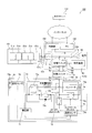
- FIG. 1st Embodiment of this invention It is a block diagram which shows the structure of the electric power generation system by 1st Embodiment of this invention. It is a figure for demonstrating the detailed structure (1st state and 4th state) of the changeover switch of the electric power generation system by 1st Embodiment shown in FIG. It is a figure for demonstrating the detailed structure (2nd state and 3rd state) of the changeover switch of the electric power generation system by 1st Embodiment shown in FIG. It is a figure for demonstrating the detailed structure (2nd state and 4th state) of the changeover switch of the electric power generation system by 1st Embodiment shown in FIG. It is a perspective view which shows the electrical storage unit of the electric power generation system by 1st Embodiment of this invention.
- the solar power generation system 1 is connected to a power generation output unit 2 that outputs power generated using sunlight and the power system 50 so that the power output by the power generation output unit 2 can be reversely flowed.
- the inverter 3 that outputs to the power system 50 side, the backup changeover switch 5 and the changeover switch 6 that are connected to the bus 4 that connects the inverter 3 and the power system 50, and the power storage unit 7 that is connected to the changeover switch 6 It has.
- the inverter 3 has a function of converting DC power output from the generated power output unit 2 into AC.
- the generated power output unit 2 is linked to the power system 50 via the inverter 3.
- a specific load 60 is connected to the changeover switch 5.
- the specific load 60 is a device driven by an AC power supply.
- the specific load 60 is desired to be always supplied with power from a power source, and includes a device that may operate at all times.
- the generated power output unit 2 includes a plurality of photovoltaic power generation modules 21 connected in series with each other.
- the photovoltaic power generation module 21 can be configured using various types of solar cells such as a thin film silicon system, a crystalline silicon system, or a compound semiconductor system.
- the solar power generation module 21 is an example of the “power generation module” in the present invention.
- the changeover switch 5 is connected to the bus 4 via the wiring 5a, and is connected to the specific load 60 via the wiring 5b.
- the changeover switch 5 is connected to the changeover switch 6 via wirings 5c and 5d and wirings 6a and 6b.
- the changeover switch 5 has a first state in which only the wiring 5a and the wiring 5b are electrically connected, and a second state in which the wiring 5a and the wiring 5c are electrically connected and the wiring 5b and the wiring 5d are connected. Can be switched.
- the wiring 5a and the wiring 5b are connected via the switch 53 that is turned on, and the wiring 5a and the wiring 5c are disconnected by the switching switch 52 that is turned off. 5d and the wiring 5b are disconnected by the changeover switch 51 which is turned off.
- the switch 53 that is turned on
- the wiring 5a and the wiring 5c are disconnected by the switching switch 52 that is turned off.
- 5d and the wiring 5b are disconnected by the changeover switch 51 which is turned off.
- the bus 4 and the power storage unit 7 side are electrically disconnected.
- the wiring 5a and the wiring 5b are disconnected by the change-over switch 53 that is turned off, and the wiring 5a and the wiring 5c are connected via the change-over switch 52 that is turned on.
- the wiring 5d and the wiring 5b are connected via a changeover switch 51 that is turned on.
- the changeover switch 5 and the changeover switch 6 are electrically connected.
- the changeover switch 5 is provided in the switchboard 8 installed indoors.
- the specific load 60 and the inverter 3 are also installed indoors.
- An AC-DC converter 72 is electrically connected to the changeover switch 6 via a wiring 6 c and a wiring 7 a of the power storage unit 7.
- the changeover switch 6 is connected to the inverter 74 a in the power storage unit 7 via the wiring 6 d and the wiring 7 b of the power storage unit 7.
- the changeover switch 6 is provided so as to be able to switch between a third state in which only the wiring 6a and the wiring 6b are connected, and a fourth state in which the wiring 6a and the wiring 6c are connected and the wiring 6b and the wiring 6d are connected.
- the inverter 74a is an example of the “power converter” and the “second power converter” in the present invention.
- the wiring 6a and the wiring 6b are connected via the switch 63 that is turned on, and the wiring 6a and the wiring 6c are disconnected by the switch 62 that is turned off.
- the wiring 6b is disconnected by the switch 61 which is turned off. Since the electrical connection between the changeover switch 6 and the power storage unit 7 is disconnected, the bus 4 and the power storage unit 7 side are electrically disconnected.
- the wiring 6a and the wiring 6b are disconnected by the switch 63 which is turned off, and the wiring 6a and the wiring 6c are connected via the switch 62 which is turned on.
- the wiring 6d and the wiring 6b are connected via a switch 61 that is turned on.
- the bus 4 and the power storage unit 7 are electrically connected via the changeover switch 5 in the second state.
- the changeover switch 5 and the changeover switch 6 can switch the current path independently of each other.
- the bus 4 and the power storage unit 7 can be electrically disconnected by operating the indoor changeover switch 5 or the outdoor changeover switch 6.
- the changeover switch 5 is switched to the first state indoors or the changeover switch 6 is switched to the third state indoors, thereby It is possible to remove the power storage unit 7 in a state where electricity is not conducted to the power storage unit 7.
- the changeover switch 5 is switched to the first state in a state where the power storage unit 7 is removed, power is supplied from the power system 50 or the generated power output unit 2 to the specific load 60 via the current path passing through the wires 5a and 5b.
- the bus 4 and the power storage unit 7 are electrically connected via the changeover switch 5 and the changeover switch 6.
- the bus 4 and the power storage unit 71 of the power storage unit 7 are connected, and the power storage unit 71 and the specific load 60 are connected.
- the power from the power system 50 or the generated power output unit 2 can be stored in the power storage unit 71, and the power from the power storage unit 71 can be supplied to the specific load 60.
- the power from the power system 50 or the generated power output unit 2 is not supplied to the power storage unit 71, and the power is supplied to the specific load 60. It is also possible to supply
- the power storage unit 7 includes a power storage unit 71 that stores power from the power system 50, an AC-DC converter 72 that converts power from alternating current to direct current, and a charge / discharge control box 73 that controls charging / discharging of the power storage unit 71.
- the AC-DC converter 72 is an example of the “power converter” and the “first power converter” in the present invention.
- the control box 74 is an example of the “control unit” in the present invention.
- the power storage unit 7 is installed outdoors, and has a wiring 7 a for receiving power from the power system 50 and a wiring 7 b for supplying power to the specific load 60.
- a wiring 7 a for receiving power from the power system 50
- a wiring 7 b for supplying power to the specific load 60.
- the power of the power system 50 can be stored in the power storage unit 71 and the stored power can be supplied to the specific load 60.
- a power generation system is configured.
- a secondary battery for example, a lithium ion storage battery that has a low spontaneous discharge and a high charge / discharge efficiency is used.
- the lithium ion storage battery has a characteristic of absorbing heat during storage.
- the charge / discharge control box 73 includes three switches 73 a, 73 b and 73 c that can be switched on / off by the control box 75.
- Switches 73 a and 73 b are connected in series in a charging path between AC-DC converter 72 and power storage unit 71.
- a diode 73d that rectifies current in a direction from the AC-DC converter 72 toward the power storage unit 71 is provided on a bypass path provided in parallel with the switch 73a.
- the switch 73 c is provided in the discharge path between the power storage unit 71 and the inverter unit 74.
- the switch 73b When charging the power storage unit 71 from the power system 50, the switch 73b is first turned on, and then the switch 73a is turned on. As a result, the reverse flow from the power storage unit 71 to the AC-DC converter 72, which occurs when the AC-DC converter 72 is just started and its output voltage is low, can be prevented by the diode 73d.
- the switch 73c when discharging from the power storage unit 71 to the specific load 60 via the inverter unit 74, the switch 73c is turned on. Further, the switch 73a is turned off, and then the switch 73b is turned off. In this case as well, backflow from the power storage unit 71 to the AC-DC converter 72 can be prevented by the diode 73d. When all of switches 73a, 73b, and 73c are turned on, both charging and discharging of power storage unit 71 can be performed.
- the inverter unit 74 includes an inverter 74a as a DC-AC converter for supplying power of the power storage unit 71 that outputs DC power to a specific load 60 driven by an AC power source, and a switch that can be switched on / off 74b.
- the switch 74b is provided between the wiring 7a and the wiring 7b.
- the switch 74b is normally turned on, and the inverter 74a turns off the switch 74b when power is supplied to the inverter 74a, preferably when power of a predetermined voltage or higher is supplied to the inverter 74a. It is configured as follows.
- a switch 77 that can be switched on / off is provided in a portion closer to the AC-DC converter 72 than the contact with the switch 74b. ing.
- the switch 77 is configured to be turned on / off according to the temperature of a temperature sensor 75a provided in the control box 75. That is, when the temperature of the temperature sensor 75a is equal to or lower than a predetermined temperature (for example, about 70 degrees), the switch 77 is turned on and power from the bus 4 side is supplied to the AC-DC converter 72. When the temperature of the temperature sensor 75a exceeds a predetermined temperature, the switch 77 is turned off, and the electrical connection between the bus 4 side and the AC-DC converter 72 is disconnected. On / off of the switch 77 is controlled by the control box 75.
- the temperature sensor 75a is an example of the “second temperature detector” in the present invention.
- the control box 75 Since the power of the control box 75 is taken from the wiring between the switch 77 and the AC-DC converter 72, when the switch 77 is turned off, the control box 75 is also driven by the power supply being lost. It is configured to stop automatically. When the control box 75 is stopped, the output from the AC-DC converter 72 is turned off (the power supply to the AC-DC converter 72 is also cut off), and the switches 73a and 73c are turned off. When the switch 73c is turned off, the power supply to the inverter 74a is cut off. Since the power supply to the inverter 74a is cut off, the switch 74b is turned on as described above.
- the switch 74b and the switch 77 are turned off and on, respectively, and the inside of the casing 76 is in an abnormal heat generation state (for example, the temperature inside the control box 75 is about Switch 70b and switch 77 are turned on and off, respectively.
- an abnormal heat generation state occurs, the AC-DC converter 72 and inverter 74a serving as a heat generation source, the power storage unit 71, and the control box are maintained while the power supply from the bus 4 side to the specific load 60 is maintained. 75 can be stopped.
- a further increase in temperature can be suppressed, so that it is possible to reduce thermal damage to each device in the housing 76. .
- a temperature sensor 78 and an exhaust fan 79 attached to the vent 79a are further provided inside the housing 76.
- the exhaust fan 79 is driven, so that the heat inside the housing 76 can be discharged to the outside.
- the temperature sensor 78 and the exhaust fan 79 are not connected to other devices (such as the power storage unit 71 and the control box 75) in the casing 76, and the power source is driven from the wiring 7a. Therefore, the temperature sensor 78 and the exhaust fan 79 operate independently from other devices (such as the power storage unit 71 and the control box 75) in the housing 76 even when the switch 77 is turned off. Configured to do.
- the temperature sensor 78 is an example of the “first temperature detector” in the present invention.
- the exhaust fan 79 is an example of the “fan” in the present invention.
- the control box 75 determines that the temperature inside the casing 76 is equal to or higher than a predetermined temperature (for example, the temperature inside the control box 75 is about 70 ° C.) based on the detection result of the temperature sensor 75a.
- the switch 77 is turned off by determining that the heat generation is abnormal.
- a normal state a state that is not an abnormal heat generation state
- on / off of each switch such as the charge / discharge control box 73, the AC-DC converter 72, and the switch 74b of the inverter unit 74 is controlled based on a predetermined program. .
- the control box 75 charges the power storage unit 71 from the power system 50 during normal operation, for example, at midnight, and when it is necessary to supply power to the specific load 60, the control box 75 sends the specific load 60 from the power storage unit 71 regardless of day or night.
- Each switch is controlled so as to supply power.
- a current path for charging the power storage unit 71 by supplying power from the bus 4 side to the power storage unit 71 is a path passing through the wiring 7a, the switch 77, the AC-DC converter 72, the switch 73a, and the switch 73b.
- the current path when the power storage unit 71 discharges and supplies power to the specific load 60 is a path that passes through the switch 73c, the inverter 74a, and the wiring 7b.
- Control box 75 controls the discharge of power storage unit 71 so that the capacity of power storage unit 71 does not fall below a predetermined threshold (for example, 50% of the fully charged state) even when discharging power storage unit 71 during normal operation. To do.
- a predetermined threshold for example, 50% of the fully charged state
- the control box 75 stops supplying power from the power storage unit 71 to the specific load 60 and directly supplies power to the specific load 60 from the bus 4. Switch each switch to supply. Specifically, the switch 73c of the charge / discharge control box 73 is turned off and the switch 74b of the inverter unit 74 is turned on.
- the output of the AC-DC converter 72 is turned off, and power charging is not performed during the daytime. However, if it exceeds the allowable voltage of the distribution line due to the reverse power flow from the customer side, or if it falls on a specific day when the power demand is expected to be significantly lower than the power generation, go to the power storage unit 71
- the AC-DC converter 72 and each switch are controlled so as to be charged.
- the supply of power from the power system 50 is stopped, so that the control box 75 is stopped. Further, the switch 77 and the switches 73a and 73b are turned off. As a result, no power is supplied to the AC-DC converter 72, and the driving of the AC-DC converter 72 is also stopped. Further, the voltage line signal of the wiring 7a is input to the switch 73c. When a power failure occurs, the switch 73c is turned on by detecting that no voltage is applied to the wiring 7a. . In addition, the inverter 74 a is configured to operate by power supply from the power storage unit 71.
- the discharge is controlled so that the remaining capacity of the power storage unit 71 does not fall below a predetermined threshold (for example, 50%) during normal operation.
- a predetermined threshold for example, 50%
- the control box 75 is charged and discharged so as to discharge even when the amount of power stored in the power storage unit 71 falls below a predetermined threshold (50% of the fully charged state).
- the power supply to the control box 75 is cut off, and the switch 73c cannot be turned on / off during the operation.
- a lithium ion storage battery is used to store power. Electric power can be used effectively.
- the power storage unit 7 includes a box-shaped casing 76 and five box-shaped lithium ion storage batteries 711, a box-shaped charge / discharge control box 73, and a box-shaped control box 75. And a box-shaped power conversion unit 700 in which the inverter unit 74 and the AC-DC converter 72 are integrally formed are housed.
- the lithium ion storage battery 711 is a pack-shaped storage battery unit in which a large number of lithium ion storage battery cells are arranged.
- a power storage unit 71 is composed of five lithium ion storage batteries 711.
- These eight devices are arranged side by side so as to be adjacent in the horizontal direction. As shown in FIGS. 5 and 6, the control box 75 and the power conversion unit 700 are adjacent to each other.
- the inverter unit 74 is arranged on the control box 75 side. That is, the AC-DC converter 72 is disposed at a position separated from the control box 75 via the inverter unit 74.
- the temperature sensor 75a of the control box 75 is disposed on the inverter unit 74 side.
- the exhaust fan 79 is provided on the side surface of the upper portion of the casing 76 and is attached to a vent 79 a communicating with the outside of the casing 76. Further, the temperature sensor 78 is disposed at a position adjacent to the exhaust fan 79.
- the heat dissipation fan 701 is an example of the “blower” in the present invention.
- the heat radiating fan 701 is arranged so as to blow air including heat inside the power conversion unit 700 from the lower surface of the power conversion unit 700 downward to the lower side (inner bottom surface side) of the casing 76.
- An air flow path 761 is provided between the inner bottom surface of the housing 76 and each device (lithium ion storage battery 711, charge / discharge control box 73, control box 75, power conversion unit 700, etc.). Thereby, the air sent by the heat radiating fan 701 is configured to flow through the lower surface side (air flow path 761) of each device including the lithium ion storage battery 711 and spread over the entire inner bottom surface of the housing 76.
- an air flow path 762 that communicates with the air flow path 761 and extends up and down is provided between the inner surface of the housing 76 and each device, and between each device (the central portion in the housing 76). Is provided.
- the air circulation path 762 has a function of circulating the air blown from the heat radiating fan 701 along the side surface of each device including the lithium ion storage battery 711 from the lower part to the upper part in the housing 76.
- the air containing the heat discharged from the power conversion unit 700 flows along the lower surface side of the lithium ion storage battery 711 through the air flow path 761 at the lower part of the casing 76.
- the air discharged from the power conversion unit 700 passes through the air flow path 762, rises along the side surface of the lithium ion storage battery 711, and spreads to the top of the housing 76.
- Air circulation paths 761 and 762 are examples of the “first distribution path” and the “second distribution path” of the present invention, respectively.
- the power storage unit 7 is configured such that the lithium ion storage battery 711 is heated using heat discharged from the power conversion unit 700 into the housing 76.
- the AC-DC converter 72 constituting the power conversion unit 700 easily generates heat, the lithium ion storage battery 711 can be easily heated using this heat.
- the lithium ion storage battery 711 is smaller than a lead storage battery or the like, the lithium ion storage battery 711 can be sufficiently heated using heat from the power conversion unit 700 in this respect.
- the lithium ion storage battery 711 is disposed in the vicinity of the power conversion unit 700 that is a heat source, the lithium ion storage battery 711 can be easily heated also in this respect.
- Each lithium ion storage battery 711, charge / discharge control box 73, and power conversion unit 700 is provided with a communication unit (not shown) for communicating the state of each device (for example, temperature state) to the control box 75. It has been.
- the communication units of each lithium ion storage battery 711 are connected in series in a daisy chain, and are configured so that five lithium ion storage batteries 711 are handled as a unit.
- the housing 76 for storing the power storage unit 71 and the AC-DC converter 72 and using the heat released from the AC-DC converter 72 into the housing 76 to heat the power storage unit 71, Even when the temperature outside the casing 76 is low, it is possible to effectively suppress a decrease in the temperature inside the casing 76 (the temperature of the power storage unit 71). As a result, even when the power storage unit 71 is installed in an environment (for example, late at night in winter or in a cold region) in which the temperature may greatly decrease, the power storage unit 71 can be sufficiently charged.
- the AC-DC necessary for charging the power storage unit 71 with the electric power from the power system 50 by heating the power storage unit 71 using the heat released from the AC-DC converter 72 into the housing 76. Since the power storage unit 71 can be heated using the converter 72, it is not necessary to separately provide a dedicated heater for heating the power storage unit 71 in the housing 76. As a result, the power storage unit 71 can be heated while suppressing an increase in the size of the housing 76 and the complexity of the configuration of the power storage unit 7 caused by providing a heater separately.
- the temperature in the casing 76 (the lithium ion storage battery 711 is heated by the heat released from the AC-DC converter 72). It is possible to effectively suppress a decrease in temperature.
- the heat dissipating fan 701 that blows the air including the heat released from the AC-DC converter 72 to the lower side in the casing 76, Since the heat sent to the lower side rises to the upper side of the casing 76, the inside of the casing 76 (five lithium ion storage batteries 711) can be heated uniformly.
- the heat radiating fan 701 provided integrally with the AC-DC converter 72, air including heat generated in the AC-DC converter 72 is blown downward in the housing 76, thereby causing the AC-DC converter 72 to
- the inside of the housing 76 (the power storage unit 71) can be heated uniformly using the heat dissipation fan 701 provided.
- the air containing heat exhausted from the power conversion unit 700 flows along the lower surface side of the lithium ion storage battery 711 through the air flow path 761 at the lower part of the casing 76 and passes through the air flow path 762 and the lithium ion storage battery 711. It circulates along the side.
- emitted from the power conversion unit 700 can be efficiently transmitted from the lower surface side and side surface side of the lithium ion storage battery 711.
- a heat dissipation fan 701 is provided in the box-shaped power conversion unit 700 in which the inverter unit 74 and the AC-DC converter 72 are configured, and air including heat inside the power conversion unit 700 is blown to the lower air flow path 761.
- the air including the heat released from the inverter unit 74 and the AC-DC converter 72 can be reliably blown to the air flow path 761.
- the heat released from the inverter unit 74 and the AC-DC converter 72 can be efficiently transmitted to the lithium ion storage battery 711.
- a common heat dissipating fan 701 for discharging the heat released from the AC-DC converter 72 and the inverter 74a from the power conversion unit 700 into the housing 76 is integrally provided at the lower part of the power conversion unit 700.
- the exhaust fan 79 is configured to discharge the heat inside the housing 76 to the outside.
- Control box 75 stops charging / discharging of power storage unit 71 when it is determined that the temperature inside casing 76 is equal to or higher than a predetermined temperature based on the detection result of temperature sensor 75a.
- a predetermined temperature based on the detection result of temperature sensor 75a.
- An inverter 74a that is housed in the housing 76 and converts electric power from direct current to alternating current or direct current is arranged on a path for supplying electric power from the electric storage unit 71 to the specific load 60 without being connected to the electric power system 50, thereby By using heat released from the inverter 74a that is driven when power is supplied from the unit 71 to the specific load 60, it is possible to more effectively suppress the temperature inside the casing 76 from being lowered. Further, in the case of the inverter 74 a that converts electric power from direct current to alternating current, the inverter 74 a is arranged on a path for supplying electric power from the power storage unit 71 to the specific load 60 without being connected to the electric power system 50. As described above, it is not necessary to use a power converter for grid interconnection (power converter such as the inverter 3) having a complicated configuration with many restrictions due to standards, and a power converter with a simple configuration can be used.
- power converter for grid interconnection power converter such as the
- the capacity of the power storage unit 71 is 7.85 kWh
- the output of the AC / DC converter 72 is 1.5 kW
- the power storage unit 71 is charged from a state where the power storage amount is 0 to a fully charged state, It is designed to charge over half of the 8 hours from 23:00 to 7:00).
- the charging time is 5 hours or more by simple calculation.
- the actual charging time is further increased.
- the capacity of the power storage unit 71 is also required to be about 3 kWh or more. Control is performed to stop discharging at 50% of the capacity of the power storage unit 71, and a capacity of about 6 kWh or more is required to continue driving the specific load 60 at a power failure of 5 hours with a capacity of 50% of full charge. Become. The value of 7.85 kWh is a value determined with a margin for this 6 kWh.
- the specific load 60 has a power consumption that is less than the storage capacity of the day and that can be driven for, for example, 5 hours or more by the stored power of the power storage unit 71.
- the specific load 60 is not used, it is difficult to set the load amount, and it is also difficult to set an appropriate capacity of the power storage unit 71.
- the rated power of the inverter 74a is 1 kW, and the power consumption of the specific load 60 is about 1 kW at the maximum.
- the volume energy density of the lead storage battery is about 50 Wh / L to 100 Wh / L, and the volume energy density of the lithium ion storage battery is about 400 Wh / L to 600 Wh / L. Therefore, when the volume energy densities of the lead storage battery and the lithium ion storage battery are 100 Wh / L and 500 Wh / L, respectively, a difference of 5 times occurs. That is, when storing the storage battery in the casing 76, the lead storage battery requires a casing 76 having a volume approximately five times that of the lithium ion storage battery. Further, the surface area of the casing 76 in this case has a difference of about twice.
- the amount of heat required to raise the inside of the casing 76 by the same temperature is the volume ratio of the casing 76 (about 5 times). And from the surface area ratio (about 2 times) there is a difference of about 10 times.
- the heat generation amount of the AC-DC converter 72 serving as a heat generation source is proportional to the output value of the AC-DC converter 72, and the output value of the AC-DC converter 72 is the capacity of the storage battery 71 as described above. Therefore, if the storage battery capacity is the same, the calorific value is the same. Therefore, regarding the temperature rise effect in the casing 76 due to the heat generated by the AC-DC converter 72, the lead storage battery is about one-tenth of the lithium ion storage battery.
- the lead storage battery radiates heat (increases the temperature in the housing 76) during charging
- a heat sink for heat dissipation must be provided in the housing 76 containing the lead storage battery in order to suppress the temperature rise during charging.
- the effect of increasing the temperature by about one tenth when the lithium ion storage battery is used is further suppressed by the heat sink, so that the difference in the effect of increasing the temperature from the present embodiment is further increased.
- the chargeable / dischargeable temperature range of the lithium ion storage battery is wider than that of the lead storage battery.
- the lithium ion storage battery can be suitably used as the power storage unit 71 of the solar power generation system 1 according to the first embodiment.
- the generated power output unit 101 selectively connects a plurality of solar power generation modules 21 a connected to each other and the power generation power of the solar power generation module 21 a to the inverter 3 side or the power storage unit 71 side of the power storage unit 7. And a switching circuit unit 101a that is switchably connected.
- the switching circuit unit 101a When the generated power output unit 101 is connected to the inverter 3 side, the switching circuit unit 101a electrically disconnects the generated power output unit 101 and the power storage unit 71 and connects the generated power output unit 101 to the power storage unit 71. When connecting to the side, the connection between the generated power output unit 101 and the inverter 3 is electrically disconnected. Further, when the switching circuit unit 101a connects the generated power output unit 101 to the inverter 3 side, the connection state of the five solar power generation modules 21a is connected to each other in series with the five solar power generation modules 21a. It is possible to switch to a serial connection state.
- the switching circuit unit 101a connects the generated power output unit 101 to the power storage unit 71 side, the five solar power generation modules 21a are connected in parallel to each other in the connection state of the five solar power generation modules 21a. It is possible to switch to a parallel connection state.
- the control part 102 which can communicate with the control box 75 of the electrical storage unit 7 is provided.
- the control unit 102 transmits a control command to the control box 75 of the power storage unit 7 based on the power generation amount of the generated power output unit 101, the charge amount of the power storage unit 71, the operation status of the inverter 3, preset setting information, and the like.
- it has a function of receiving information related to the power storage unit 7 such as the power storage amount of the power storage unit 71 from the control box 75.
- the control unit 102 switches the switching circuit unit 101a of the generated power output unit 101 based on the power generation amount of the generated power output unit 101, the charge amount of the power storage unit 71, the operation status of the inverter 3, preset setting information, and the like. And the like.
- control unit 102 determines whether the system is in normal operation or in an emergency based on the amount of charge in power storage unit 71, the operating status of inverter 3, and preset setting information. .
- control unit 102 When the control unit 102 determines that it is during normal operation, the control unit 102 switches the connection state of the photovoltaic power generation module 21a to the serial connection state and switches the connection destination of the generated power output unit 101 to the inverter 3 side.
- the circuit unit 101a is controlled. During normal operation, the output power of the generated power output unit 101 is consumed by the specific load 60 or the like, and the surplus power is reversely flowed to the power system 50.
- control unit 102 determines that it is an emergency, the control unit 102 switches the connection state of the photovoltaic power generation module 21a to the parallel connection state and switches the connection destination of the generated power output unit 101 to the power storage unit 71 side.
- the circuit unit 101a is controlled.
- the output power of the generated power output unit 101 is supplied to the power storage unit 71, and the specific load 60 is driven by the charging power of the power storage unit 71 and the output power of the generated power output unit 101.
- the control unit 102 is based on the detection results of the current detection unit 103 provided on the generated power output unit 101 side of the inverter 3 and the current detection unit 104 provided on the power system 50 side of the inverter 3. It is possible to detect the power generation amount, the reverse power flow amount (power sales amount), the power consumption amount at the specific load 60, and the like.
- the control unit 102 also generates power from the solar power generation module 21a, reverse power flow amount (power sales amount), power consumption at the specific load 60, the state of the power storage unit 71 (charge amount, temperature state, etc.), and other solar power.
- Information on the photovoltaic system 100 is configured to be transmitted to the external server 150 via the Internet.
- This external server 150 is a server of a maintenance company of the photovoltaic power generation system 100, for example. Thereby, the maintenance company can grasp the state of the photovoltaic power generation system 100 at any time.
- the external server 150 can be accessed from the user's PC (personal computer) 160 or the like via the Internet, and the user can check the state of the solar power generation system 100 using the PC 160. Is possible.
- the specific load 60 can be driven for a longer time.
- the electrical storage unit 800 of the electric power generation system by 3rd Embodiment of this invention is demonstrated.
- the inverter unit 874 and the AC-DC converter unit 872 are provided as separate units.
- any of the said 1st Embodiment and 2nd Embodiment may be applied as a structure of electric power generation systems other than the electrical storage unit 800, description is abbreviate
- the AC-DC converter unit 872 is an example of the “power conversion unit” in the present invention.
- the inverter unit 874 is an example of the “power conversion unit” in the present invention.
- the power storage unit 800 in the third embodiment includes a box-shaped inverter unit 874 and a box-shaped AC-DC converter unit 872 as individual units.
- Inverter unit 874 and AC-DC converter unit 872 accommodate inverter 74a and AC-DC converter 72, respectively.
- the power storage unit 800 further includes two lithium ion storage batteries 711, a box-shaped charge / discharge control box 73, and a box-shaped control box 75, and is configured by a total of six box-shaped units.
- Each unit is arranged so as to be adjacent to each other in each column in 3 rows and 2 columns when seen in a plan view.
- the AC-DC converter unit 872 and the inverter unit 874 are arranged in the front row (lower side in FIG. 9) of the power storage unit 800, and the lithium ion storage battery 711 and the control box 75 are arranged in the center row.
- a lithium ion storage battery 711 and a charge / discharge control box 73 are arranged.
- Two heat dissipating fans 801 for discharging heat generated by driving the inverter 74a from the inverter unit 874 into the housing 76 are integrally provided at the bottom of the box-shaped inverter unit 874.
- two heat radiating fans 802 for discharging heat generated by driving the AC-DC converter 72 into the housing 76 are integrally provided below the box-shaped AC-DC converter unit 872.
- two radiating fans 801 and 802 are provided in each of the inverter unit 874 and the AC-DC converter unit 872 provided separately.
- the heat radiating fan 801 is arranged so as to blow air including heat inside the inverter unit 874 downward from the lower surface of the inverter unit 874 to the lower side (inner bottom surface side) of the housing 76. Further, the heat radiating fan 802 blows air including heat inside the AC-DC converter unit 872 downward from the lower surface of the AC-DC converter unit 872 to the lower side (inner bottom surface side) of the casing 76. Has been placed.
- the remaining configuration of the third embodiment is the same as that of the first embodiment.
- the inverter unit 874 and the AC-DC converter unit 872 are provided as separate units, so that the inverter unit 874 and the AC-DC converter unit 872 that are heat sources are provided inside the casing 76. It is possible to increase the surface area exposed (in contact with air) at. As a result, the heat generated by the inverter 74a and the AC-DC converter 72, which are heat sources, can be released more efficiently into the housing 76, and thus the housing 76 due to the heat generated by the inverter 74a and the AC-DC converter 72. The temperature rise effect can be further improved.
- both the inverter unit 874 and the AC-DC converter unit 872 are provided with two heat dissipating fans 801 and 802, respectively. Therefore, the inverter 74a and the AC-DC converter 72 A larger amount of the air containing the generated heat can be sent to the air flow path 761 (762). This makes it possible to increase the amount of air when circulating air containing heat generated by the inverter 74a and the AC-DC converter 72 in the housing 76. As a result, the heat generated by the inverter 74a and the AC-DC converter 72 can be more efficiently transferred to the lithium ion storage battery 711.
- the present invention is not limited thereto, and other DC power generation devices or wind power generation devices may be used as power generation modules.
- a power generation module that generates power using natural energy of may be used.
- the lithium ion storage battery 711 is used as the power storage unit 71 .
- the present invention is not limited to this, and other secondary batteries may be used.
- a storage battery such as a nickel hydride storage battery or a lead storage battery may be used.
- a capacitor may be used instead of the storage battery.
- the device driven by the AC power source is shown as an example of the specific load 60, but a device driven by the DC power source may be used.
- a DC-DC converter that performs voltage conversion between direct current and direct current is used between the power storage unit 71 and the specific load 60 in place of the inverter 74a that converts direct current to alternating current.
- the power storage unit 71 and the specific load 60 are directly connected.
- a DC load and an AC load may be mixed.
- the temperature sensor 78 and the exhaust fan 79 are provided in the power storage unit 7.
- the present invention is not limited to this, and the temperature sensor 78 and the exhaust fan 79 are not provided. Also good.
- the power conversion unit 700 may be disposed so as to be surrounded by a plurality of lithium ion storage batteries 711 as in the power storage unit 200 of the modification shown in FIG.
- each lithium ion storage battery 711 and the power conversion unit 700 can be arrange
- the said 1st and 2nd embodiment showed the example which ventilated the heat
- the present invention is not limited to this, and the power storage unit 7 may be installed indoors. In addition, it is more effective when the power storage unit 7 is installed in an environment where the air temperature may greatly decrease.
Landscapes
- Engineering & Computer Science (AREA)
- Chemical & Material Sciences (AREA)
- Chemical Kinetics & Catalysis (AREA)
- Electrochemistry (AREA)
- General Chemical & Material Sciences (AREA)
- Manufacturing & Machinery (AREA)
- Power Engineering (AREA)
- Supply And Distribution Of Alternating Current (AREA)
- Secondary Cells (AREA)
- Charge And Discharge Circuits For Batteries Or The Like (AREA)
- Battery Mounting, Suspending (AREA)
- Cooling Or The Like Of Electrical Apparatus (AREA)
Abstract
この蓄電ユニット(7)は、電力を直流又は交流に変換することにより熱を放出する電力変換器(72、74a)と、電力を蓄電する蓄電部(71)と、少なくとも蓄電部および電力変換器を収納する筐体(76)と、筐体内に設けられた送風機(701)とを備え、送風機は、電力変換器から放出される熱を含む空気を、蓄電部が配置された筐体内に送風するように構成されている。
Description
本発明は、蓄電ユニットおよび発電システムに関し、特に、電力を蓄電可能な蓄電部を備えた蓄電ユニットおよび発電システムに関する。
従来、電力を蓄電可能な蓄電池を備えた発電システムが知られている。このような発電システムは、たとえば、特開平11-127546号公報に開示されている。
この発電システムでは、太陽光発電モジュールが電力系統に連系されている。そして、太陽光発電モジュールには、太陽光発電モジュールの発電電力を蓄電可能なように蓄電池が接続されている。また、蓄電池は、電力系統からも充電することが可能に構成され、電力系統からの蓄電池による充電を電気料金の安い深夜に行うことが開示されている。
しかしながら、蓄電池を備えた発電システムにおいては、蓄電池を屋外に設置する場合がある。ここで、蓄電池の充電性能は、所定の温度範囲以下では大きく低下してしまい、十分に充電を行うことができなくなることが一般的に知られている。したがって、この発電システムの蓄電池を屋外に設置した場合においては、たとえば、冬季などには蓄電池の温度が低下してしまうので、蓄電池への充電を十分に行うことが困難になる場合があるという問題点がある。さらに、冬季の深夜では気温が大きく低下して、容易に蓄電池の温度が所定の温度範囲を下回ってしまうので、深夜に充電を行うことが困難になるという問題点がある。
この発明は、上記のような課題を解決するためになされたものであり、この発明の1つの目的は、気温が大きく低下する可能性のある環境に蓄電部を設置する場合にも、蓄電池の充電を十分に行うことが可能な蓄電ユニットおよび発電システムを提供することである。
この発明の第1の局面による蓄電ユニットは、電力を直流又は交流に変換することにより熱を放出する電力変換器と、電力を蓄電する蓄電部と、少なくとも蓄電部および電力変換器を収納する筐体と、筐体内に設けられた送風機とを備え、送風機は、電力変換器から放出される熱を含む空気を、蓄電部が配置された筐体内に送風するように構成されている。
この発明の第2の局面による発電システムは、電力系統に連系され、自然エネルギーを用いて発電する発電モジュールと、電力系統からの電力を直流に変換する電力変換器と、少なくとも電力変換器により直流に変換された電力を蓄電する蓄電部と、少なくとも蓄電部および電力変換器を収納する筐体と、筐体内に設けられた送風機とを備え、送風機は、電力変換器から放出される熱を含む空気を、蓄電部が配置された筐体内に送風するように構成されている。
本発明によれば、筐体内の蓄電部の温度が低下することを効果的に抑制することができる。これにより、気温が大きく低下する可能性のある環境に蓄電池を設置する場合にも、蓄電池の充電を十分に行うことができる。また、筐体内に蓄電部を加熱するための専用のヒータを別途設ける必要がないので、ヒータを別途設けることに起因する筐体の大型化および蓄電ユニットの構成の複雑化などを抑制しながら、蓄電部を加熱することができる。
以下、本発明の実施形態を図面に基づいて説明する。
(第1実施形態)
まず、図1~図7を参照して、本発明の第1実施形態による発電システム(太陽光発電システム1)の構造を説明する。
まず、図1~図7を参照して、本発明の第1実施形態による発電システム(太陽光発電システム1)の構造を説明する。
太陽光発電システム1は、太陽光を用いて発電した電力を出力する発電電力出力部2と、電力系統50に接続され、発電電力出力部2により出力された電力を逆潮流が可能となるように電力系統50側に出力するインバータ3と、インバータ3および電力系統50を接続する母線4に接続されたバックアップ用の切替スイッチ5および切替スイッチ6と、切替スイッチ6に接続された蓄電ユニット7とを備えている。
インバータ3は、発電電力出力部2から出力された直流の電力を交流に変換する機能を有している。発電電力出力部2は、インバータ3を介して電力系統50に連系されている。
切替スイッチ5には特定負荷60が接続されている。特定負荷60は、交流電源によって駆動される機器である。特定負荷60には、常に電源から電力が供給されていることが望まれ、常時動作する可能性のある機器が含まれる。
発電電力出力部2は、互いに直列接続された複数の太陽光発電モジュール21を含んでいる。太陽光発電モジュール21は、薄膜シリコン系や結晶シリコン系、或いは化合物半導体系など、種々の太陽電池を用いて構成することができる。なお、太陽光発電モジュール21は、本発明の「発電モジュール」の一例である。
切替スイッチ5は、配線5aを介して母線4に接続されており、配線5bを介して特定負荷60に接続されている。切替スイッチ5は、配線5cおよび5dと配線6aおよび6bとを介して切替スイッチ6に接続されている。切替スイッチ5は、配線5aと配線5bとのみを電気的に接続する第1状態と、配線5aと配線5cとを電気的に接続するとともに、配線5bと配線5dとを接続する第2状態とを切り替え可能に設けられている。
第1状態では、配線5aと配線5bとがオンになった切替スイッチ53を介して接続されており、配線5aと配線5cとの間はオフになった切替スイッチ52により切断されており、配線5dと配線5bとの間はオフになった切替スイッチ51により切断されている。この第1状態では、切替スイッチ5と切替スイッチ6との間で電気的な接続が切断されているので、母線4と蓄電ユニット7側とは電気的に切り離されている。
第2状態では、配線5aと配線5bとの間はオフになった切替スイッチ53により切断されており、配線5aと配線5cとの間はオンになった切替スイッチ52を介して接続されており、配線5dと配線5bとの間はオンになった切替スイッチ51を介して接続されている。この第2状態では、切替スイッチ5と切替スイッチ6とが電気的に接続される。
切替スイッチ5は、屋内に設置されている配電盤8に設けられている。また、特定負荷60およびインバータ3も屋内に設置されている。
切替スイッチ6には、配線6cおよび蓄電ユニット7の配線7aを介してAC-DCコンバータ72が電気的に接続されている。また、切替スイッチ6は、配線6dおよび蓄電ユニット7の配線7bを介して蓄電ユニット7内のインバータ74aと接続されている。切替スイッチ6は、配線6aと配線6bとのみを接続する第3状態と、配線6aと配線6cとを接続するとともに、配線6bと配線6dとを接続する第4状態とを切り替え可能に設けられている。なお、インバータ74aは、本発明の「電力変換器」および「第2電力変換器」の一例である。
第3状態では、配線6aと配線6bとがオンになったスイッチ63を介して接続されており、配線6aと配線6cとの間はオフになったスイッチ62により切断されており、配線6dと配線6bとの間はオフになったスイッチ61により切断されている。切替スイッチ6と蓄電ユニット7との間で電気的な接続が切断されているので、母線4と蓄電ユニット7側とは電気的に切り離されている。また、第4状態では、配線6aと配線6bとの間がオフになったスイッチ63により切断されており、配線6aと配線6cとの間はオンになったスイッチ62を介して接続されており、配線6dと配線6bとの間はオンになったスイッチ61を介して接続されている。この第4状態では、切替スイッチ6と蓄電ユニット7とが電気的に接続されているので、第2状態の切替スイッチ5を介して母線4と蓄電ユニット7とが電気的に接続されている。
また、切替スイッチ5と切替スイッチ6とは互いに独立して電流経路を切り替えることが可能である。第1実施形態では、屋内の切替スイッチ5または屋外の切替スイッチ6を操作することにより、母線4と蓄電ユニット7とを電気的に切り離すことが可能である。これにより、たとえば蓄電ユニット7の修理等を行う場合には、屋内において切替スイッチ5を第1状態に切り替えるか、または、屋外において切替スイッチ6を第3状態に切り替えることにより、母線4側からの電気が蓄電ユニット7に導通しない状態で蓄電ユニット7を取り外すことが可能である。また、蓄電ユニット7を取り外した状態において切替スイッチ5が第1状態に切り替えられることにより、配線5aおよび5bを通る電流経路を介して特定負荷60に電力系統50または発電電力出力部2から電力が直接供給される。また、蓄電ユニット7を取り外した状態において切替スイッチ5および切替スイッチ6をそれぞれ第2状態および第3状態にした場合においても、同様に、配線5a、5c、6a、6b、5dおよび5bを通る電流経路を介して、特定負荷60に電力系統50または発電電力出力部2から直接電力が供給される。
また、切替スイッチ5を第2状態とし、切替スイッチ6を第4状態とした場合には、母線4と蓄電ユニット7とが切替スイッチ5および切替スイッチ6を介して電気的に接続される。この状態では、後述するように、母線4と蓄電ユニット7の蓄電部71とが接続されるとともに、蓄電部71と特定負荷60とが接続される。これにより、電力系統50または発電電力出力部2からの電力を蓄電部71に蓄電可能であるとともに、蓄電部71からの電力を特定負荷60に供給可能な状態となる。また、蓄電ユニット7内部のスイッチの切り替えによって蓄電ユニット7内の電流経路を切り替えることにより、電力系統50または発電電力出力部2からの電力を蓄電部71に供給せずに、特定負荷60に電力を供給することも可能である。
次に、蓄電ユニット7の構造について説明する。
蓄電ユニット7は、電力系統50からの電力を蓄電する蓄電部71と、電力を交流から直流に変換するAC-DCコンバータ72と、蓄電部71の充放電を制御するための充放電制御ボックス73と、蓄電部71または母線4から特定負荷60側に電力を供給するためのインバータユニット74と、蓄電部71、AC-DCコンバータ72および充放電制御ボックス73などの機器の制御を行うコントロールボックス75とを主に備えている。これらの機器は、筐体76の内部にまとめて収納されており、1つのユニットとして扱うことが可能である。なお、AC-DCコンバータ72は、本発明の「電力変換器」および「第1電力変換器」の一例である。コントロールボックス74は、本発明の「制御部」の一例である。
この蓄電ユニット7を屋外に設置しており、電力系統50から電力を受け取るための配線7aと、特定負荷60に電力を供給するための配線7bとを有している。配線7aおよび配線7bをそれぞれ屋外に設けられた切替スイッチ6の配線6cおよび6dに接続することにより、電力系統50の電力を蓄電部71に蓄電し、蓄電した電力を特定負荷60に供給可能な発電システムが構成されている。
また、蓄電部71としては、自然放電が少なく、充放電効率の高い2次電池(たとえば、リチウムイオン蓄電池)が用いられている。なお、リチウムイオン蓄電池は、蓄電時に吸熱する特性を有している。
充放電制御ボックス73は、コントロールボックス75によりオン/オフの切り替えが可能な3つのスイッチ73a、73bおよび73cを含んでいる。スイッチ73aおよび73bは、AC-DCコンバータ72と蓄電部71との間の充電経路において直列に接続されている。またスイッチ73aと並列に設けられたバイパス経路上に、AC-DCコンバータ72から蓄電部71に向かう方向に電流を整流するダイオード73dが設けられている。スイッチ73cは、蓄電部71とインバータユニット74との間の放電経路に設けられている。
電力系統50から蓄電部71に充電する場合には、まずスイッチ73bがオンにされ、次いでスイッチ73aがオンにされる。これにより、AC-DCコンバータ72が起動直後であってその出力電圧が低い場合に生じる、蓄電部71からAC-DCコンバータ72への逆流を、ダイオード73dによって防止することが可能である。
また、蓄電部71からインバータユニット74を介して特定負荷60に放電する場合には、スイッチ73cがオンにされる。また、スイッチ73aをオフにし、次いでスイッチ73bをオフにする。この場合にも同様に、蓄電部71からAC-DCコンバータ72への逆流をダイオード73dによって防止することが可能である。なお、スイッチ73a、73bおよび73cの全てがオンにされた場合には、蓄電部71の充電と放電との両方を行うことが可能である。
インバータユニット74は、直流電力を出力する蓄電部71の電力を交流電源で駆動される特定負荷60に供給するための直流-交流変換器としてのインバータ74aと、オン/オフの切り替えが可能なスイッチ74bとを含んでいる。スイッチ74bは、配線7aと配線7bとの間に設けられている。スイッチ74bは通常オンになっており、インバータ74aは、インバータ74aに電力が供給される場合、好ましくは、インバータ74aに所定の電圧以上の電力が供給されている場合に、スイッチ74bをオフにするように構成されている。
また、配線7aとAC-DCコンバータ72との間の電流経路のうち、スイッチ74bとの接点よりもAC-DCコンバータ72側の部分には、オン/オフの切り替えが可能なスイッチ77が設けられている。このスイッチ77は、コントロールボックス75内に設けられた温度センサ75aの温度に応じてオン/オフが切り替わるように構成されている。すなわち、温度センサ75aの温度が所定の温度(たとえば、約70度)以下である場合にはスイッチ77はオンとなり、母線4側からの電力がAC-DCコンバータ72に供給される。また、温度センサ75aの温度が所定の温度を上回った場合にはスイッチ77はオフとなり、母線4側とAC-DCコンバータ72との電気的な接続が切断される。スイッチ77のオン/オフは、コントロールボックス75によって制御される。温度センサ75aは、本発明の「第2温度検知部」の一例である。
なお、コントロールボックス75の電力は、スイッチ77とAC-DCコンバータ72との間の配線から取っているので、スイッチ77がオフになった場合には、電源がなくなることによりコントロールボックス75の駆動も自動的に停止するように構成されている。また、コントロールボックス75が停止した場合、AC-DCコンバータ72からの出力がオフにされ(AC-DCコンバータ72への電力供給も断たれている)、スイッチ73aおよび73cがオフにされる。スイッチ73cがオフにされることによって、インバータ74aへの電力供給が断たれるように構成されている。インバータ74aへの電力供給が断たれるので、上述のようにスイッチ74bはオンになる。スイッチ74bをオンにすることにより、切替スイッチ5および切替スイッチ6がそれぞれ第2状態および第4状態の場合に、配線7a、スイッチ74bおよび配線7bを介した電流経路を介して、母線4側からの電力を蓄電部71を介さずに特定負荷60に供給することが可能となる。
したがって、筐体76内の温度が低い状態では、スイッチ74bおよびスイッチ77はそれぞれオフおよびオンにされており、筐体76内の内部が異常発熱状態(たとえば、コントロールボックス75の内部の温度が約70℃以上)になった場合に、スイッチ74bおよびスイッチ77がそれぞれオンおよびオフにされる。これにより、異常発熱状態になった場合には、母線4側から特定負荷60への電力供給を維持したまま、発熱源となるAC-DCコンバータ72およびインバータ74aや、蓄電部71、およびコントロールボックス75を停止することが可能である。このため、筐体76の内部が異常発熱状態になった場合に、さらなる温度上昇を抑制することができるので、筐体76内の各機器が受ける熱的なダメージを低減することが可能である。
筐体76の内部には、温度センサ78と通気口79aに取り付けられた排気ファン79とがさらに設けられている。温度センサ78の検知温度が所定の温度(約40℃)以上になった場合に、排気ファン79が駆動されることにより、筐体76の内部の熱を外部へ排出することが可能である。なお、温度センサ78および排気ファン79は、筐体76内の他の機器(蓄電部71、コントロールボックス75など)とは接続されておらず、また電源は配線7aから取って駆動される。このため、温度センサ78および排気ファン79は、スイッチ77がオフになった場合にも、筐体76内の他の機器(蓄電部71、コントロールボックス75など)から電気的に独立して動作を行うように構成されている。温度センサ78は、本発明の「第1温度検知部」の一例である。排気ファン79は、本発明の「ファン」の一例である。
コントロールボックス75は、温度センサ75aの検知結果に基づいて、筐体76の内部の温度が所定の温度(たとえば、コントロールボックス75の内部の温度が約70℃)以上であると判断した場合に、異常発熱状態であると判断して、スイッチ77をオフにする。また、正常状態(異常発熱状態ではない状態)では、所定のプログラムなどに基づき、充放電制御ボックス73、AC-DCコンバータ72、インバータユニット74のスイッチ74bなどの各スイッチのオン/オフを制御する。
コントロールボックス75は、通常運転時、たとえば、深夜においては電力系統50から蓄電部71に充電を行い、特定負荷60に電力を供給する必要が生じたときには昼夜を問わず蓄電部71から特定負荷60に電力を供給するように、各スイッチを制御する。母線4側から蓄電部71に電力を供給して蓄電部71を充電する際の電流経路は、配線7a、スイッチ77、AC-DCコンバータ72、スイッチ73aおよびスイッチ73bを通る経路である。また、蓄電部71が放電して特定負荷60に電力を供給する際の電流経路は、スイッチ73c、インバータ74aおよび配線7bを通る経路である。なお、蓄電部71に蓄電された電力は電力系統50には供給されない。コントロールボックス75は、通常運転時に蓄電部71の放電を行う場合にも、蓄電部71の容量が所定の閾値(たとえば、満充電状態の50%)以下にならないように蓄電部71の放電を制御する。コントロールボックス75は、蓄電部71の容量が閾値以下になったと判断した場合には、蓄電部71から特定負荷60に電力を供給するのを停止するとともに、母線4から直接特定負荷60に電力を供給するように各スイッチを切り替える。具体的には、充放電制御ボックス73のスイッチ73cをオフにするとともに、インバータユニット74のスイッチ74bをオンにする。この時、AC-DCコンバータ72の出力はオフとし、昼間時間帯での電力充電は行わない。ただし、需要家側からの逆潮流によって配電線の許容電圧を越える場合、或いは電力需要量が電力発電量を大きく下回ることが予想されるような特定日に該当する場合には、蓄電部71への充電が行われるようにAC-DCコンバータ72および各スイッチを制御する。
停電時などの非常時には、電力系統50からの電力の供給が停止するので、コントロールボックス75が停止される。また、スイッチ77、スイッチ73aおよび73bがオフにされる。これにより、AC-DCコンバータ72にも電力が供給されないので、AC-DCコンバータ72の駆動も停止される。また、スイッチ73cには配線7aの電圧線信号が入力されており、停電した場合には、配線7aに電圧がかかっていないことを検知して、スイッチ73cがオンになるように構成されている。また、インバータ74aは、蓄電部71からの電力供給によって稼動するように構成されている。
第1実施形態では、通常運転時に蓄電部71の残容量が所定の閾値(たとえば、50%)以下にならないように放電を制御している。この結果、停電時などの非常時における蓄電部71の特定負荷60への放電開始時には、蓄電部71に必ず閾値(満充電状態の50%)より大きい電力が蓄電されている。ここで、停電時においては、通常運転時と異なり、コントロールボックス75は、蓄電部71の蓄電量が所定の閾値(満充電状態の50%)以下になっても放電するように充放電制御ボックス73を制御する。非常時にはコントロールボックス75への電力の供給が断たれており、途中でスイッチ73cのオン/オフの切り替えは不可能であるが、第1実施形態のように、たとえばリチウムイオン蓄電池を用いることによって蓄電電力を有効に利用することが可能である。
次に、蓄電ユニット7の構成を説明する。
図5~図7に示すように、蓄電ユニット7は、箱状の筐体76内に箱状の5つのリチウムイオン蓄電池711と、箱状の充放電制御ボックス73と、箱状のコントロールボックス75と、インバータユニット74およびAC-DCコンバータ72が一体的に構成された箱状の電力変換ユニット700とが収納されている。リチウムイオン蓄電池711は、内部に多数のリチウムイオン蓄電池セルを配したパック状の蓄電池ユニットである。5つのリチウムイオン蓄電池711から蓄電部71が構成されている。これらの8個の機器(5つのリチウムイオン蓄電池711、充放電制御ボックス73、コントロールボックス75および電力変換ユニット700)は、横方向に隣接するように並べて配置されている。図5および図6に示すように、コントロールボックス75と電力変換ユニット700とは隣接している。電力変換ユニット700において、インバータユニット74はコントロールボックス75側に配置されている。すなわち、AC-DCコンバータ72はコントロールボックス75に対してインバータユニット74を介して離間した位置に配置されている。コントロールボックス75の温度センサ75aは、インバータユニット74側に配置されている。排気ファン79は、筐体76の上部の側面に設けられ、筐体76の外部と連通する通気口79aに取り付けられている。また、温度センサ78は、排気ファン79に隣接した位置に配置されている。
また、電力変換ユニット700の下部にはAC-DCコンバータ72およびインバータ74aの駆動により発生する熱を電力変換ユニット700から筐体76内に排出するための2つの放熱ファン701が一体的に設けられている。放熱ファン701は、本発明の「送風機」の一例である。この放熱ファン701は、電力変換ユニット700内部の熱を含む空気を電力変換ユニット700の下面から下方に向けて筐体76の下方側(内部底面側)に送風するように配置されている。
筐体76の内部底面と各機器(リチウムイオン蓄電池711、充放電制御ボックス73、コントロールボックス75、電力変換ユニット700など)との間には空気流通経路761が設けられている。これにより、放熱ファン701により送られた空気がリチウムイオン蓄電池711を含む各機器の下面側(空気流通経路761)を流通して筐体76の内部底面全体に拡がるように構成されている。また、筐体76の内側面と各機器との間、および、各機器同士の間(筐体76内の中央部)には、空気流通経路761と連通し、上下に延びる空気流通経路762が設けられている。空気流通経路762は、リチウムイオン蓄電池711を含む各機器の側面に沿って放熱ファン701から送風された空気を筐体76内の下部から上部まで流通させる機能を有する。これにより、電力変換ユニット700から排出される熱を含む空気は、筐体76の下部の空気流通経路761を通りリチウムイオン蓄電池711の下面側に沿って流通する。その後、電力変換ユニット700から排出される空気は、空気流通経路762を通りリチウムイオン蓄電池711の側面に沿って上昇し、筐体76の上部まで拡がる。この結果、電力変換ユニット700から排出される熱がリチウムイオン蓄電池711に効率的に伝達される。空気流通経路761および762は、それぞれ、本発明の「第1流通経路」および「第2流通経路」の一例である。
蓄電ユニット7では、電力変換ユニット700から筐体76内に排出された熱を利用して、リチウムイオン蓄電池711が加熱されるように構成されている。特に、電力変換ユニット700を構成するAC-DCコンバータ72は発熱し易いので、この熱を利用してリチウムイオン蓄電池711を容易に加熱することが可能である。また、リチウムイオン蓄電池711は、鉛蓄電池などに比べると小型であるので、この点では、電力変換ユニット700からの熱を利用して十分にリチウムイオン蓄電池711を加熱することが可能である。また、発熱源である電力変換ユニット700の近傍にリチウムイオン蓄電池711が配置されているので、この点でも、リチウムイオン蓄電池711を容易に加熱することが可能になる。筐体76の内部に蓄えられた熱は、筐体76内の温度が所定の温度(約40℃)よりも高い場合に、排気ファン79によって筐体76の上部から排出される。また、各リチウムイオン蓄電池711、充放電制御ボックス73および電力変換ユニット700には、各機器の状態(たとえば、温度状態など)をコントロールボックス75に通信するための通信部(図示せず)が設けられている。各リチウムイオン蓄電池711の通信部同士は、直列に数珠つなぎ状にデイジーチェーン(daisy chain)接続され、5つのリチウムイオン蓄電池711が一体として扱われるように構成されている。
蓄電部71およびAC-DCコンバータ72を収納する筐体76を設け、AC-DCコンバータ72から筐体76内に放出される熱を利用して蓄電部71を加熱するように構成することによって、筐体76の外部の気温が低い場合にも、筐体76内の温度(蓄電部71の温度)が低下することを効果的に抑制することができる。これにより、気温が大きく低下する可能性のある環境(たとえば、冬季の深夜や寒冷地域など)に蓄電部71を設置する場合にも、蓄電部71の充電を十分に行うことができる。また、AC-DCコンバータ72から筐体76内に放出される熱を利用して蓄電部71を加熱することによって、電力系統50からの電力を蓄電部71に充電するために必要なAC-DCコンバータ72を用いて蓄電部71を加熱することができるので、筐体76内に蓄電部71を加熱するための専用のヒータを別途設ける必要がない。これにより、ヒータを別途設けることに起因する筐体76の大型化および蓄電ユニット7の構成の複雑化などを抑制しながら、蓄電部71を加熱することができる。
充電時に吸熱して雰囲気温度を低下させる特性を有するリチウムイオン蓄電池711を用いた場合に特に、AC-DCコンバータ72から放出される熱による加熱によって、筐体76内の温度(リチウムイオン蓄電池711の温度)が低下することを効果的に抑制することができる。
また、第1実施形態では、上記のように、AC-DCコンバータ72から放出される熱を含む空気を筐体76内の下方側に送風する放熱ファン701を設けることによって、一旦筐体76の下方側に送られた熱は筐体76の上方側に上昇するので、筐体76の内部(5つのリチウムイオン蓄電池711)を均一に加熱することができる。
AC-DCコンバータ72と一体的に設けられた放熱ファン701を用いてAC-DCコンバータ72において発生する熱を含む空気を筐体76内の下方側に送風することによって、AC-DCコンバータ72に備わっている放熱ファン701を用いて、筐体76の内部(蓄電部71)を均一に加熱することができる。
電力変換ユニット700から排出される熱を含む空気は、筐体76の下部の空気流通経路761を通りリチウムイオン蓄電池711の下面側に沿って流通するとともに、空気流通経路762を通りリチウムイオン蓄電池711の側面に沿って流通する。このように構成することによって、電力変換ユニット700から排出される熱をリチウムイオン蓄電池711の下面側および側面側から効率よく伝達することができる。
インバータユニット74およびAC-DCコンバータ72が構成された箱状の電力変換ユニット700に放熱ファン701を設け、電力変換ユニット700内部の熱を含む空気を下方の空気流通経路761に送風するように構成することによって、インバータユニット74およびAC-DCコンバータ72から放出される熱を含む空気を確実に空気流通経路761に送風することができる。この結果、インバータユニット74およびAC-DCコンバータ72から放出される熱を、リチウムイオン蓄電池711に効率よく伝達することができる。
電力変換ユニット700の下部にAC-DCコンバータ72およびインバータ74aから放出される熱を電力変換ユニット700から筐体76内に排出する共通の放熱ファン701が一体的に設けられている。このように構成することによって、蓄電部71への充電時にAC-DCコンバータ72から放出される熱と、蓄電部71から特定負荷60への電力供給時にインバータ74aから放出される熱との両方を利用して蓄電部71を加熱することができる。さらに、共通の放熱ファン701を用いることにより部品点数が増加するのを抑制することができる。
温度センサ78の検知温度が所定の温度(約40℃)以上になった場合に、排気ファン79が筐体76の内部の熱を外部へ排出するように構成されている。このように構成することによって、蓄電部71が必要以上に加熱されるのを抑制することができるので、蓄電部71の充電性能が低下しない適切な温度範囲で蓄電部71の充放電を行うことができる。
コントロールボックス75は、温度センサ75aの検知結果に基づいて、筐体76の内部の温度が所定の温度以上であると判断した場合に蓄電部71の充放電を停止する。このように構成することによって、筐体76の内部の温度が上昇した場合にも、温度センサ75aの検知結果に基づいて蓄電ユニット7の内部における発熱(充放電)を停止させることができるので、蓄電部71の過剰な温度上昇を抑制することができる。
筐体76に収納され、電力を直流から交流または直流に変換するインバータ74aを電力系統50には接続されずに蓄電部71から特定負荷60に電力を供給する経路上に配置することによって、蓄電部71から特定負荷60に電力を供給する際に駆動されるインバータ74aから放出される熱を用いて、さらに効果的に筐体76の内部の温度が低下することを抑制することができる。また、電力を直流から交流に変換するインバータ74aの場合に、そのインバータ74aを電力系統50に接続せずに蓄電部71から特定負荷60に電力を供給する経路上に配置することによって、インバータ74aとして、規格による制約が多く複雑な構成を有する系統連系用の電力変換器(インバータ3のような電力変換器)を用いる必要がなく、簡単な構成の電力変換器を用いることができる。
次に、上記第1実施形態の太陽光発電システム1の具体的な実施例について説明する。
蓄電部71の容量を7.85kWh、AC/DCコンバータ72の出力を1.5kWとし、蓄電部71を蓄電量が0の状態から満充電状態まで充電する際に、深夜電力時間帯(たとえば、23時から7時までの8時間など)の半分以上を費やして充電するように設計している。この場合、充電時間は単純計算では5時間以上となる。リチウムイオン蓄電池では、満充電付近では充電速度を遅く制御する必要があるので、実際の充電時間はさらに長くなる。
また、特定負荷60の消費電力を約600Whとした場合、5時間の特定負荷60の駆動には約3kWhの電力量が必要となり、5時間の停電時に蓄電部71から特定負荷60に電力を供給する場合には、蓄電部71の容量も約3kWh以上必要となる。蓄電部71の容量の50%で放電を停止する制御を行っており、満充電の50%の容量で5時間の停電時に特定負荷60を駆動させ続けるには、約6kWh以上の容量が必要になる。7.85kWhの値は、この6kWhに余裕を見て決定した値である。
蓄電部71に蓄電した電力を、短時間で放電しきるように使用せず、長時間をかけて出力させることを前提として設計している。好ましくは、特定負荷60は、一日の使用電力量が蓄電容量よりも小さく、蓄電部71の蓄電電力によってたとえば5時間以上の駆動を賄える程度の消費電力とする。特定負荷60としない場合には、負荷量の設定が困難であり、適切な蓄電部71の容量の設定も困難になる。この実施例では、インバータ74aの定格電力を1kWとし、特定負荷60の消費電力は最大でも1kW程度とする。
上記の実施例の構成を前提として、蓄電部71としてリチウムイオン蓄電池を用いた場合と鉛蓄電池を用いた場合との差異について説明する。
鉛蓄電池の体積エネルギー密度は、約50Wh/L~100Wh/Lであり、リチウムイオン蓄電池の体積エネルギー密度は、約400Wh/L~600Wh/Lである。したがって、鉛蓄電池およびリチウムイオン蓄電池の体積エネルギー密度をそれぞれ100Wh/Lおよび500Wh/Lとした場合、5倍の差が生じる。すなわち、蓄電池を筐体76に収納する場合、鉛蓄電池の場合はリチウムイオン蓄電池の場合と比べて、約5倍の体積の筐体76が必要になる。また、この場合の筐体76の表面積は、約2倍の差が生じる。筐体76の表面積の大きさは、筐体76の放熱量に比例すると考えられるので、筐体76内を同じ温度だけ上げるために必要な熱量は、筐体76の体積比(約5倍)および表面積比(約2倍)から、約10倍の差が生じる。
第1実施形態において発熱源となるAC-DCコンバータ72の発熱量はAC-DCコンバータ72の出力値に比例し、上記の前提のように、AC-DCコンバータ72の出力値は蓄電池71の容量に応じて決められるので、蓄電池容量が同じであれば、発熱量も同じとなる。したがって、AC-DCコンバータ72の発熱による筐体76内の温度上昇効果については、鉛蓄電池はリチウムイオン蓄電池の約10分の1となる。
また、鉛蓄電池は充電時に放熱(筐体76内の温度を上昇させる)するので、充電時の温度上昇を抑制するために鉛蓄電池を収納した筐体76に放熱のためのヒートシンクが設けられることが多い。この場合には、リチウムイオン蓄電池を用いた場合の約10分の1の温度上昇効果が、ヒートシンクによりさらに抑制されるので、本実施例との温度上昇効果の差が一層大きくなる。
また、充放電可能温度範囲もリチウムイオン蓄電池は鉛蓄電池よりも広い。
以上の点から、リチウムイオン蓄電池は第1実施形態による太陽光発電システム1の蓄電部71として好適に用いることができる。
(第2実施形態)
次に、図8を参照して、本発明の第2実施形態による発電システム(太陽光発電システム100)について説明する。この第2実施形態では、上記第1実施形態と異なり、太陽光発電モジュール21aによる発電電力を蓄電部71に蓄電可能に構成した例について説明する。
次に、図8を参照して、本発明の第2実施形態による発電システム(太陽光発電システム100)について説明する。この第2実施形態では、上記第1実施形態と異なり、太陽光発電モジュール21aによる発電電力を蓄電部71に蓄電可能に構成した例について説明する。
第2実施形態では、発電電力出力部101は、互いに接続された複数の太陽光発電モジュール21aと、太陽光発電モジュール21aの発電電力をインバータ3側または蓄電ユニット7の蓄電部71側に選択的に切替可能に接続する切替回路部101aとを含んでいる。
切替回路部101aは、発電電力出力部101をインバータ3側に接続する場合には、発電電力出力部101と蓄電部71との接続を電気的に切断し、発電電力出力部101を蓄電部71側に接続する場合には、発電電力出力部101とインバータ3との接続を電気的に切断するように構成されている。また、切替回路部101aは、発電電力出力部101をインバータ3側に接続する場合には、5つの太陽光発電モジュール21a同士の接続状態を、5つの太陽光発電モジュール21aが互いに直列接続された直列接続状態に切り替えることが可能である。また、切替回路部101aは、発電電力出力部101を蓄電部71側に接続する場合には、5つの太陽光発電モジュール21a同士の接続状態を、5つの太陽光発電モジュール21aが互いに並列接続された並列接続状態に切り替えることが可能である。
蓄電ユニット7のコントロールボックス75と通信可能な制御部102が設けられている。制御部102は、発電電力出力部101の発電量、蓄電部71の充電量、インバータ3の動作状況および予め設定された設定情報などに基づいて、蓄電ユニット7のコントロールボックス75に制御指令を送信するとともに、コントロールボックス75から蓄電部71の蓄電量などの蓄電ユニット7に関する情報を受信する機能を有する。また、制御部102は、発電電力出力部101の発電量、蓄電部71の充電量、インバータ3の動作状況および予め設定された設定情報などに基づいて、発電電力出力部101の切替回路部101aなどを制御する機能を有する。具体的には、制御部102は、蓄電部71の充電量、インバータ3の動作状況および予め設定された設定情報などに基づいて、システムが通常運転時であるか非常時であるかを判断する。
制御部102は、通常運転時であると判断した場合には、太陽光発電モジュール21aの接続状態を直列接続状態にするとともに、発電電力出力部101の接続先をインバータ3側に切り替えるように切替回路部101aを制御する。通常運転時においては、発電電力出力部101の出力電力は、特定負荷60等において消費され、余った電力は電力系統50に逆潮流される。
制御部102は、非常時であると判断した場合には、太陽光発電モジュール21aの接続状態を並列接続状態にするとともに、発電電力出力部101の接続先を蓄電部71側に切り替えるように切替回路部101aを制御する。非常時においては、発電電力出力部101の出力電力は、蓄電部71に供給され、特定負荷60は、蓄電部71の充電電力および発電電力出力部101の出力電力によって駆動される。
制御部102は、インバータ3の発電電力出力部101側に設けられた電流検知部103およびインバータ3の電力系統50側に設けられた電流検知部104の検知結果に基づいて、太陽光発電モジュール21aの発電量、逆潮流電力量(売電量)および特定負荷60における電力消費量などを検知することが可能である。また、制御部102は、太陽光発電モジュール21aの発電量、逆潮流電力量(売電量)、特定負荷60における電力消費量および蓄電部71の状態(充電量、温度状態など)、その他の太陽光発電システム100の情報をインターネットを介して外部サーバ150に送信するように構成されている。この外部サーバ150は、たとえば、太陽光発電システム100のメンテナンス会社のサーバである。これにより、太陽光発電システム100の状態をメンテナンス会社が随時把握することが可能である。また、この外部サーバ150にはユーザのPC(パーソナルコンピュータ)160などからインターネットを介してアクセスすることが可能であり、ユーザはPC160を用いて自己の太陽光発電システム100の状態を確認することが可能である。
第2実施形態の上記以外の構成は、上記第1実施形態と同様である。
第2実施形態では、非常時において、太陽光発電モジュール21aの発電電力を蓄電部71に蓄電することができるので、より長時間特定負荷60を駆動することができる。
第2実施形態のその他の効果は、上記第1実施形態と同様である。
(第3実施形態)
次に、図9および図10を参照して、本発明の第3実施形態による発電システムの蓄電ユニット800について説明する。この第3実施形態では、上記第1実施形態と異なり、インバータユニット874およびAC-DCコンバータユニット872を、それぞれ個別のユニットとして設けた例について説明する。なお、蓄電ユニット800以外の発電システムの構成としては、上記第1実施形態および第2実施形態のいずれを適用してもよいので、説明は省略する。なお、AC-DCコンバータユニット872は、本発明の「電力変換ユニット」の一例である。また、インバータユニット874は、本発明の「電力変換ユニット」の一例である。
次に、図9および図10を参照して、本発明の第3実施形態による発電システムの蓄電ユニット800について説明する。この第3実施形態では、上記第1実施形態と異なり、インバータユニット874およびAC-DCコンバータユニット872を、それぞれ個別のユニットとして設けた例について説明する。なお、蓄電ユニット800以外の発電システムの構成としては、上記第1実施形態および第2実施形態のいずれを適用してもよいので、説明は省略する。なお、AC-DCコンバータユニット872は、本発明の「電力変換ユニット」の一例である。また、インバータユニット874は、本発明の「電力変換ユニット」の一例である。
第3実施形態における蓄電ユニット800は、箱状のインバータユニット874および箱状のAC-DCコンバータユニット872を、それぞれ個別のユニットとして備えている。インバータユニット874およびAC-DCコンバータユニット872、それぞれ、内部にインバータ74aおよびAC-DCコンバータ72を収容している。また、蓄電ユニット800は、2つのリチウムイオン蓄電池711と、箱状の充放電制御ボックス73と、箱状のコントロールボックス75とをさらに備え、合計6つの箱状のユニットから構成されている。各ユニットは、平面的に見て、3行2列で列毎に互いに隣接するように配列されている。具体的には、蓄電ユニット800の手前側(図9の下側)の行にAC-DCコンバータユニット872およびインバータユニット874が配置され、中央の行にはリチウムイオン蓄電池711およびコントロールボックス75が配置され、奥側の行にはリチウムイオン蓄電池711および充放電制御ボックス73が配置されている。
箱状のインバータユニット874の下部には、インバータ74aの駆動により発生する熱をインバータユニット874から筐体76内に排出するための2つの放熱ファン801が一体的に設けられている。また、箱状のAC-DCコンバータユニット872の下部には、AC-DCコンバータ72の駆動により発生する熱を筐体76内に排出するための2つの放熱ファン802が一体的に設けられている。このように、第3実施形態では、個別に設けられたインバータユニット874およびAC-DCコンバータユニット872の両方に、それぞれ放熱ファン801および802が2つずつ設けられている。放熱ファン801は、インバータユニット874の内部の熱を含む空気をインバータユニット874の下面から下方に向けて筐体76の下方側(内部底面側)に送風するように配置されている。また、放熱ファン802は、AC-DCコンバータユニット872の内部の熱を含む空気をAC-DCコンバータユニット872の下面から下方に向けて筐体76の下方側(内部底面側)に送風するように配置されている。
なお、第3実施形態の上記以外の構成は、上記第1実施形態と同様である。
第3実施形態では、上記のように、インバータユニット874およびAC-DCコンバータユニット872を個別のユニットとして設けたことにより、発熱源であるインバータユニット874およびAC-DCコンバータユニット872が筐体76内部において露出する(空気と触れる)表面積を大きくすることが可能である。これにより、発熱源であるインバータ74aおよびAC-DCコンバータ72で発生した熱をより効率的に筐体76内に放出することができるので、インバータ74aおよびAC-DCコンバータ72の発熱による筐体76内の温度上昇効果をさらに向上させることができる。
また、第3実施形態では、上記のように、インバータユニット874およびAC-DCコンバータユニット872の両方に、それぞれ放熱ファン801および802を2つずつ設けたので、インバータ74aおよびAC-DCコンバータ72で発生した熱を含んだ空気をより大量に空気流通経路761(762)に送り出すことができる。これにより、筐体76内部において、インバータ74aおよびAC-DCコンバータ72で発生した熱を含んだ空気を循環させる際の空気量を増大させることが可能である。この結果、インバータ74aおよびAC-DCコンバータ72で発生する熱を、リチウムイオン蓄電池711にさらに効率良く伝達することができる。
なお、今回開示された実施形態は、すべての点で例示であって制限的なものではないと考えられるべきである。本発明の範囲は、上記した実施形態の説明ではなく特許請求の範囲によって示され、さらに特許請求の範囲と均等の意味および範囲内でのすべての変更が含まれる。
たとえば、上記第1および第2実施形態では、太陽光発電モジュール21によって発電を行う例について説明したが、本発明はこれに限らず、発電モジュールとして他の直流発電装置あるいは風力発電装置などの他の自然エネルギーを用いて発電する発電モジュールを用いてもよい。
また、上記第1および第2実施形態では、蓄電部71としてリチウムイオン蓄電池711を用いる例を示したが、本発明はこれに限らず、他の2次電池を用いてもよい。たとえば、ニッケル水素蓄電池や鉛蓄電池などの蓄電池を用いてもよい。また、本発明の「蓄電部」の一例として、蓄電池の代わりにキャパシタを用いてもよい。
また、上記第1および第2実施形態では、特定負荷60の例として交流電源で駆動させる機器を示したが、直流電源で駆動される機器を用いてもよい。この場合、蓄電部71と特定負荷60との間には、直流から交流に変換するインバータ74aに代えて直流と直流との電圧変換を行うDC-DCコンバータが用いられる。或いは、蓄電部71と特定負荷60との間が直接接続される。さらに、特定負荷60として、直流負荷および交流負荷が混在してもよい。
また、上記第1および第2実施形態では、蓄電ユニット7に温度センサ78および排気ファン79を設けた例を示したが、本発明はこれに限らず、温度センサ78および排気ファン79がなくてもよい。
また、上記第1および第2実施形態では、筐体76内において、各機器の中で電力変換ユニット700を端に配置した例を示したが、本発明はこれに限らず、適宜配置を変えてもよい。たとえば、図11に示す変形例の蓄電ユニット200のように、電力変換ユニット700を複数のリチウムイオン蓄電池711で囲うように配置してもよい。これにより、各リチウムイオン蓄電池711と電力変換ユニット700とを近くに配置することができるので、電力変換ユニット700から排出される熱を用いてより効果的に各リチウムイオン蓄電池711を加熱することができる。
また、上記第1および第2実施形態では、電力変換ユニット700に内蔵された放熱ファン701により電力変換ユニット700において発生する熱を筐体76の下方側に送風した例を示したが、本発明はこれに限られない。すなわち、電力変換ユニット700と別体で設けられたファンにより電力変換ユニット700において発生する熱を筐体76の下方側に送風してもよい。
また、上記第1および第2実施形態では、リチウムイオン蓄電池711、充放電制御ボックス73、電力変換ユニット700およびコントロールボックス75を横に並べて配置した例について説明したが、本発明はこれに限らず、これらの機器の全部または一部を上下に重ねて配置してもよい。
また、上記第1および第2実施形態では、切替スイッチ5および6を設けた例を示したが、本発明はこれに限らず、切替スイッチ5および6のいずれか一方のみを設けるようにしてもよいし、切替スイッチを設けなくてもよい。
また、上記第1および第2実施形態では、蓄電ユニット7を屋外に設置する例について説明したが、本発明はこれに限らず、蓄電ユニット7を屋内に設置してもよい。また、その他、気温が大きく低下する可能性のある環境に蓄電ユニット7を設置する場合に、より有効である。
Claims (15)
- 電力を直流又は交流に変換することにより熱を放出する電力変換器と、
電力を蓄電する蓄電部と、
少なくとも前記蓄電部および前記電力変換器を収納する筐体と、
前記筐体内に設けられた送風機とを備え、
前記送風機は、前記電力変換器から放出される熱を含む空気を、前記蓄電部が配置された前記筐体内に送風するように構成されている、蓄電ユニット。 - 前記蓄電部は、蓄電する際に吸熱する特性を有している、請求項1に記載の蓄電ユニット。
- 前記蓄電部は、1または複数のリチウムイオン蓄電池からなる、請求項2に記載の蓄電ユニット。
- 前記送風機は、前記電力変換器の下方側に設けられている、請求項1に記載の蓄電ユニット。
- 前記送風機は、前記電力変換器から放出される熱を含む空気を前記筐体内の下方側に送風するように構成されている、請求項4に記載の蓄電ユニット。
- 前記電力変換器から放出される熱を前記筐体外に放出するファンをさらに備える、請求項1に記載の蓄電ユニット。
- 前記筐体内部に配置され、内部に前記電力変換器を収容する箱状の電力変換ユニットをさらに備え、
前記送風機は、前記電力変換ユニット内部の空気を前記電力変換ユニット外部の前記筐体内に送風するように構成されている、請求項1に記載の蓄電ユニット。 - 前記筐体は、第1流通経路を有し、
前記第1流通経路は、前記筐体内の下部に設けられるとともに、前記送風機により前記筐体内の下方側に送風された空気を少なくとも前記筐体内部の前記蓄電部の配置位置まで流通させるように構成されている、請求項5に記載の蓄電ユニット。 - 前記筐体は、第2流通経路をさらに有し、
前記第2流通経路は、前記第1流通経路と連通し、前記送風機により送風された空気を前記蓄電部の側面に沿って前記筐体内の下部から上部まで流通させるように構成されている、請求項8に記載の蓄電ユニット。 - 前記筐体の上部に設けられた通気口を備える、請求項1に記載の蓄電ユニット。
- 前記電力変換器は、第1電力変換器及び第2電力変換器を含み、
前記第1電力変換器は、電力系統からの電力を直流に変換するとともに、変換した電力を前記蓄電部または所定の負荷に供給し、
前記第2電力変換器は、電力系統には接続されておらず、前記蓄電部からの電力を交流に変換するとともに、変換した電力を前記所定の負荷に供給するように構成されている、請求項1に記載の蓄電ユニット。 - 前記送風機は、前記第1電力変換器及び前記第2電力変換器の下方側に備えられ、
前記第1電力変換器及び前記第2電力変換器から放出される熱を含む空気を前記筐体内の下方側に送風するように構成されている、請求項11に記載の蓄電ユニット。 - 前記筐体内において前記ファンの近傍に設けられ、前記筐体内部の温度を検知する第1温度検知部をさらに備え、
前記ファンは、前記第1温度検知部の検知結果に基づいて、前記筐体内部の空気を外部へ排出する、請求項6に記載の蓄電ユニット。 - 前記筐体内に設けられ前記電力変換器の近傍の温度を検知する第2温度検知部と、
少なくとも前記第2温度検知部の検知結果に基づいて、前記蓄電部への充放電の制御を行う制御部とをさらに備える、請求項1に記載の蓄電ユニット。 - 電力系統に連系され、自然エネルギーを用いて発電する発電モジュールと、
前記電力系統からの電力を直流に変換する電力変換器と、
少なくとも前記電力変換器により直流に変換された電力を蓄電する蓄電部と、
少なくとも前記蓄電部および前記電力変換器を収納する筐体と、
前記筐体内に設けられた送風機とを備え、
前記送風機は、前記電力変換器から放出される熱を含む空気を、前記蓄電部が配置された前記筐体内に送風するように構成されている、発電システム。
Priority Applications (2)
| Application Number | Priority Date | Filing Date | Title |
|---|---|---|---|
| JP2011544282A JPWO2011068151A1 (ja) | 2009-12-04 | 2010-12-02 | 蓄電ユニットおよび発電システム |
| US13/485,096 US20120235481A1 (en) | 2009-12-04 | 2012-05-31 | Storage Unit and Power Generation System |
Applications Claiming Priority (2)
| Application Number | Priority Date | Filing Date | Title |
|---|---|---|---|
| JP2009-276103 | 2009-12-04 | ||
| JP2009276103 | 2009-12-04 |
Related Child Applications (1)
| Application Number | Title | Priority Date | Filing Date |
|---|---|---|---|
| US13/485,096 Continuation US20120235481A1 (en) | 2009-12-04 | 2012-05-31 | Storage Unit and Power Generation System |
Publications (1)
| Publication Number | Publication Date |
|---|---|
| WO2011068151A1 true WO2011068151A1 (ja) | 2011-06-09 |
Family
ID=44114997
Family Applications (1)
| Application Number | Title | Priority Date | Filing Date |
|---|---|---|---|
| PCT/JP2010/071558 WO2011068151A1 (ja) | 2009-12-04 | 2010-12-02 | 蓄電ユニットおよび発電システム |
Country Status (3)
| Country | Link |
|---|---|
| US (1) | US20120235481A1 (ja) |
| JP (1) | JPWO2011068151A1 (ja) |
| WO (1) | WO2011068151A1 (ja) |
Cited By (4)
| Publication number | Priority date | Publication date | Assignee | Title |
|---|---|---|---|---|
| JP2013077466A (ja) * | 2011-09-30 | 2013-04-25 | Sanyo Electric Co Ltd | 蓄電装置 |
| KR101409999B1 (ko) | 2012-05-16 | 2014-06-20 | 엘지전자 주식회사 | 에너지 저장장치 |
| JP2015162969A (ja) * | 2014-02-27 | 2015-09-07 | 株式会社Nttファシリティーズ | 電力システム、蓄電制御装置、制御方法、及びプログラム |
| JP2017130467A (ja) * | 2017-04-17 | 2017-07-27 | パナソニックIpマネジメント株式会社 | 蓄電システムおよび制御システム |
Families Citing this family (6)
| Publication number | Priority date | Publication date | Assignee | Title |
|---|---|---|---|---|
| EP2512000B1 (en) * | 2011-04-15 | 2022-03-02 | ABB Schweiz AG | Reconfigurable power systems and converters |
| DE102012104005A1 (de) * | 2012-05-07 | 2013-11-07 | Adensis Gmbh | Photovoltaikanlage und Verfahren zum Betreiben einer Photovoltaikanlage zur Einspeisung von elektrischer Leistung in ein Mittelspannungsnetz |
| US20150039141A1 (en) * | 2013-07-30 | 2015-02-05 | Wayne State University | System and method using fuzzy logic for resource conservation |
| US9929449B2 (en) | 2014-06-10 | 2018-03-27 | Vertiv Energy Systems, Inc. | Systems and methods for warming batteries |
| RU2709628C2 (ru) * | 2015-03-17 | 2019-12-19 | Филипс Лайтинг Холдинг Б.В. | Возбудитель по меньшей мере с четырьмя различными состояниями |
| ES2695630B2 (es) * | 2017-07-03 | 2019-07-30 | Power Electronics Espana S L | Sistema de alimentacion intrinseco para servicios auxiliares de convertidores de potencia |
Citations (8)
| Publication number | Priority date | Publication date | Assignee | Title |
|---|---|---|---|---|
| JPH04293610A (ja) * | 1991-03-25 | 1992-10-19 | Suzuki Motor Corp | 車両用換気装置 |
| JPH04372537A (ja) * | 1991-06-21 | 1992-12-25 | Sanyo Electric Co Ltd | 複合入力装置 |
| JPH0965582A (ja) * | 1995-08-23 | 1997-03-07 | Nec Corp | 太陽電池を利用した電源システム |
| JPH0983167A (ja) * | 1995-09-20 | 1997-03-28 | Fujitsu Ltd | 屋外設置電子装置筐体 |
| JPH09285025A (ja) * | 1996-04-15 | 1997-10-31 | Tec Corp | 2次電池内蔵電子機器 |
| JP2000021457A (ja) * | 1998-07-03 | 2000-01-21 | Hitachi Ltd | 蓄電システム |
| JP2008041376A (ja) * | 2006-08-04 | 2008-02-21 | Toyota Motor Corp | 車両用組電池の暖冷機システム |
| JP2008213740A (ja) * | 2007-03-06 | 2008-09-18 | Toyota Motor Corp | 電気機器の冷却装置、その冷却方法および冷却方法をコンピュータで実現されるプログラムならびにそのプログラムを記録した記録媒体 |
Family Cites Families (8)
| Publication number | Priority date | Publication date | Assignee | Title |
|---|---|---|---|---|
| JPH0795771A (ja) * | 1993-09-20 | 1995-04-07 | Sansha Electric Mfg Co Ltd | 電源装置の冷却構造 |
| JP2001338486A (ja) * | 2000-05-25 | 2001-12-07 | Hitachi Ltd | 情報記憶装置 |
| US6784641B2 (en) * | 2000-09-20 | 2004-08-31 | Toshiba Battery Co., Ltd. | Uninterruptible power supply |
| JP4673019B2 (ja) * | 2004-09-10 | 2011-04-20 | 日立コンピュータ機器株式会社 | 情報処理装置 |
| US20060120001A1 (en) * | 2004-12-03 | 2006-06-08 | Weber William J | Modular power supply assembly |
| CN101202529A (zh) * | 2006-12-11 | 2008-06-18 | 丹佛斯传动有限公司 | 电子装置及电动机变频器 |
| US7643281B2 (en) * | 2006-12-13 | 2010-01-05 | Hitachi, Ltd. | Storage controller |
| TWI457749B (zh) * | 2010-06-21 | 2014-10-21 | Acbel Polytech Inc | High power density power supplies for miniaturized servers |
-
2010
- 2010-12-02 WO PCT/JP2010/071558 patent/WO2011068151A1/ja active Application Filing
- 2010-12-02 JP JP2011544282A patent/JPWO2011068151A1/ja active Pending
-
2012
- 2012-05-31 US US13/485,096 patent/US20120235481A1/en not_active Abandoned
Patent Citations (8)
| Publication number | Priority date | Publication date | Assignee | Title |
|---|---|---|---|---|
| JPH04293610A (ja) * | 1991-03-25 | 1992-10-19 | Suzuki Motor Corp | 車両用換気装置 |
| JPH04372537A (ja) * | 1991-06-21 | 1992-12-25 | Sanyo Electric Co Ltd | 複合入力装置 |
| JPH0965582A (ja) * | 1995-08-23 | 1997-03-07 | Nec Corp | 太陽電池を利用した電源システム |
| JPH0983167A (ja) * | 1995-09-20 | 1997-03-28 | Fujitsu Ltd | 屋外設置電子装置筐体 |
| JPH09285025A (ja) * | 1996-04-15 | 1997-10-31 | Tec Corp | 2次電池内蔵電子機器 |
| JP2000021457A (ja) * | 1998-07-03 | 2000-01-21 | Hitachi Ltd | 蓄電システム |
| JP2008041376A (ja) * | 2006-08-04 | 2008-02-21 | Toyota Motor Corp | 車両用組電池の暖冷機システム |
| JP2008213740A (ja) * | 2007-03-06 | 2008-09-18 | Toyota Motor Corp | 電気機器の冷却装置、その冷却方法および冷却方法をコンピュータで実現されるプログラムならびにそのプログラムを記録した記録媒体 |
Cited By (4)
| Publication number | Priority date | Publication date | Assignee | Title |
|---|---|---|---|---|
| JP2013077466A (ja) * | 2011-09-30 | 2013-04-25 | Sanyo Electric Co Ltd | 蓄電装置 |
| KR101409999B1 (ko) | 2012-05-16 | 2014-06-20 | 엘지전자 주식회사 | 에너지 저장장치 |
| JP2015162969A (ja) * | 2014-02-27 | 2015-09-07 | 株式会社Nttファシリティーズ | 電力システム、蓄電制御装置、制御方法、及びプログラム |
| JP2017130467A (ja) * | 2017-04-17 | 2017-07-27 | パナソニックIpマネジメント株式会社 | 蓄電システムおよび制御システム |
Also Published As
| Publication number | Publication date |
|---|---|
| US20120235481A1 (en) | 2012-09-20 |
| JPWO2011068151A1 (ja) | 2013-04-18 |
Similar Documents
| Publication | Publication Date | Title |
|---|---|---|
| JP5673551B2 (ja) | 蓄電ユニット、発電システムおよび充放電システム | |
| WO2011068151A1 (ja) | 蓄電ユニットおよび発電システム | |
| JP5824614B2 (ja) | 充放電システム | |
| CN102906951B (zh) | 配电装置及使用该配电装置的配电系统 | |
| US10439429B2 (en) | Modular microgrid unit and method of use | |
| JP5935046B2 (ja) | 蓄電池集合体制御システム | |
| EP2355291B1 (en) | Modular electric power system with a renewable energy power generating apparatus | |
| TW201131938A (en) | High voltage direct current uninterruptible power supply system with multiple input sources of power | |
| KR101294807B1 (ko) | 독립형 태양광 발전시스템의 제어장치 및 제어방법 | |
| JP2011125124A (ja) | サーバーとサーバーに収納される無停電電源装置 | |
| ES2676346T3 (es) | Dispositivo y procedimiento para conmutar un sistema de gestión de batería | |
| CN102150341B (zh) | 具有集成光伏电板和电池的光伏系统 | |
| WO2011068133A1 (ja) | 充放電システム、発電システムおよび充放電制御装置 | |
| JP2017201876A (ja) | 太陽光モジュール、及びそれを備える太陽光システム | |
| KR20230052034A (ko) | 에너지 저장장치 | |
| JP6062699B2 (ja) | パワーコンディショナ及びこれを備える蓄電システム | |
| WO2012133186A1 (ja) | スイッチ回路制御部及び充放電システム | |
| KR20240110352A (ko) | 에너지 저장장치 | |
| JP2015065770A (ja) | 蓄電システム | |
| JP7165507B2 (ja) | 直流給電システム | |
| KR101550589B1 (ko) | 발전 관리 장치 및 그를 갖는 태양광 발전 시스템 | |
| KR102639780B1 (ko) | 에너지 저장장치 | |
| KR20240011506A (ko) | 에너지 저장장치 | |
| KR102723313B1 (ko) | 에너지 저장장치 | |
| WO2011068156A1 (ja) | 蓄電システムおよび切替装置 |
Legal Events
| Date | Code | Title | Description |
|---|---|---|---|
| 121 | Ep: the epo has been informed by wipo that ep was designated in this application |
Ref document number: 10834601 Country of ref document: EP Kind code of ref document: A1 |
|
| WWE | Wipo information: entry into national phase |
Ref document number: 2011544282 Country of ref document: JP |
|
| NENP | Non-entry into the national phase |
Ref country code: DE |
|
| 122 | Ep: pct application non-entry in european phase |
Ref document number: 10834601 Country of ref document: EP Kind code of ref document: A1 |