WO2011055614A1 - 内視鏡システム - Google Patents
内視鏡システム Download PDFInfo
- Publication number
- WO2011055614A1 WO2011055614A1 PCT/JP2010/067951 JP2010067951W WO2011055614A1 WO 2011055614 A1 WO2011055614 A1 WO 2011055614A1 JP 2010067951 W JP2010067951 W JP 2010067951W WO 2011055614 A1 WO2011055614 A1 WO 2011055614A1
- Authority
- WO
- WIPO (PCT)
- Prior art keywords
- image
- visual field
- field image
- unit
- endoscope
- Prior art date
Links
Images


Classifications
-
- A—HUMAN NECESSITIES
- A61—MEDICAL OR VETERINARY SCIENCE; HYGIENE
- A61B—DIAGNOSIS; SURGERY; IDENTIFICATION
- A61B1/00—Instruments for performing medical examinations of the interior of cavities or tubes of the body by visual or photographical inspection, e.g. endoscopes; Illuminating arrangements therefor
- A61B1/04—Instruments for performing medical examinations of the interior of cavities or tubes of the body by visual or photographical inspection, e.g. endoscopes; Illuminating arrangements therefor combined with photographic or television appliances
- A61B1/042—Instruments for performing medical examinations of the interior of cavities or tubes of the body by visual or photographical inspection, e.g. endoscopes; Illuminating arrangements therefor combined with photographic or television appliances characterised by a proximal camera, e.g. a CCD camera
-
- A—HUMAN NECESSITIES
- A61—MEDICAL OR VETERINARY SCIENCE; HYGIENE
- A61B—DIAGNOSIS; SURGERY; IDENTIFICATION
- A61B1/00—Instruments for performing medical examinations of the interior of cavities or tubes of the body by visual or photographical inspection, e.g. endoscopes; Illuminating arrangements therefor
- A61B1/00002—Operational features of endoscopes
- A61B1/00004—Operational features of endoscopes characterised by electronic signal processing
- A61B1/00009—Operational features of endoscopes characterised by electronic signal processing of image signals during a use of endoscope
- A61B1/000094—Operational features of endoscopes characterised by electronic signal processing of image signals during a use of endoscope extracting biological structures
-
- A—HUMAN NECESSITIES
- A61—MEDICAL OR VETERINARY SCIENCE; HYGIENE
- A61B—DIAGNOSIS; SURGERY; IDENTIFICATION
- A61B1/00—Instruments for performing medical examinations of the interior of cavities or tubes of the body by visual or photographical inspection, e.g. endoscopes; Illuminating arrangements therefor
- A61B1/00002—Operational features of endoscopes
- A61B1/00043—Operational features of endoscopes provided with output arrangements
- A61B1/00045—Display arrangement
- A61B1/0005—Display arrangement combining images e.g. side-by-side, superimposed or tiled
-
- A—HUMAN NECESSITIES
- A61—MEDICAL OR VETERINARY SCIENCE; HYGIENE
- A61B—DIAGNOSIS; SURGERY; IDENTIFICATION
- A61B1/00—Instruments for performing medical examinations of the interior of cavities or tubes of the body by visual or photographical inspection, e.g. endoscopes; Illuminating arrangements therefor
- A61B1/00163—Optical arrangements
- A61B1/00174—Optical arrangements characterised by the viewing angles
- A61B1/00177—Optical arrangements characterised by the viewing angles for 90 degrees side-viewing
-
- A—HUMAN NECESSITIES
- A61—MEDICAL OR VETERINARY SCIENCE; HYGIENE
- A61B—DIAGNOSIS; SURGERY; IDENTIFICATION
- A61B1/00—Instruments for performing medical examinations of the interior of cavities or tubes of the body by visual or photographical inspection, e.g. endoscopes; Illuminating arrangements therefor
- A61B1/00163—Optical arrangements
- A61B1/00174—Optical arrangements characterised by the viewing angles
- A61B1/00181—Optical arrangements characterised by the viewing angles for multiple fixed viewing angles
Definitions
- the present invention relates to an endoscope system, and more particularly to an endoscope system capable of simultaneously observing a direct viewing direction and a side viewing direction.
- An endoscope system including an endoscope that captures a subject inside a subject and an image processing device that generates an observation image of the subject captured by the endoscope, such as a medical field and an industrial field. Widely used.
- Japanese Patent Laid-Open No. 2008-309860 discloses a subject image in a direct viewing direction corresponding to the central axis direction and a subject image in all directions in a side viewing direction substantially orthogonal to the central axis direction.
- An acquirable optical system and an endoscope including the optical system are disclosed.
- an image in a direct view direction (direct view field image) having a circular shape and an outer periphery of the image in the direct view direction An image of the entire circumference in the side view direction (side view field image) having an annular shape is displayed on a display unit such as a monitor.
- the display size of the image in each visual field direction can be reduced by adopting the display mode as described above.
- an image with reduced visibility is displayed as a result of having to reduce the size of the direct-view type endoscope or the side-view type endoscope.
- the present invention has been made in view of the above-described circumstances, and is an endoscope capable of simultaneously observing the direct viewing direction and the side viewing direction and improving the visibility in an image in one viewing direction.
- the purpose is to provide a system.
- An endoscope system includes an endoscope that acquires a direct-view visual field image and a side-view visual field image of an observation object, and a detection unit that acquires a predetermined detection result based on a predetermined output signal or predetermined output information Generating an observation image comprising the direct-view visual field image and the side-view visual field image in the same screen, and based on the predetermined detection result, one of the direct-view visual field image and the side-view visual field image And an image processing unit that performs a process of displaying the enlarged view field image on the display unit and changing the display mode of the other view field image on the display unit.
- the figure which shows the structure of the endoscope system which concerns on the Example of this invention The perspective view which shows the structure of the front-end
- the front view which shows the structure of the front-end
- the figure which shows the structure of the principal part in a 2nd Example The figure which shows the structure of the principal part in the modification of a 2nd Example.
- the figure which shows the structure of the principal part in a 3rd Example The figure which shows the structure of the principal part in a 4th Example.
- the figure which shows an example of the display mode when the direct-view visual field image is expanded in the observation image of FIG. The figure which shows an example of the display mode when the side view visual field image is expanded in the observation image of FIG.
- the figure which shows an example at the time of displaying only the side view visual field image of the range which is not covered with the enlarged direct view visual field image among the original images of the side view visual field image of FIG. The figure which shows an example at the time of displaying the compressed image which performed the image compression process with respect to this original image, maintaining the visual field range of the original image of the side view visual field image of FIG.
- an endoscope system 1 includes an endoscope 2 that images an observation object and outputs an imaging signal, and a light source device 31 that supplies illumination light for illuminating the observation object. And a video processor 32 that generates and outputs a video signal corresponding to the imaging signal, and a monitor 35 that displays an observation image corresponding to the video signal.
- the endoscope 2 includes an operation unit 3 that an operator holds and operates, an elongated insertion unit 4 that is formed on the distal end side of the operation unit 3 and is inserted into a body cavity and the like, and a side portion of the operation unit 3 And a universal cord 5 provided with one end so as to extend from.
- the insertion portion 4 includes a hard distal end portion 6 provided on the most distal end side, a bendable bending portion 7 provided on the rear end of the distal end portion 6, and a long and long side provided on the rear end of the bending portion 7. And a flexible tube portion 8 having flexibility. Further, the bending portion 7 performs a bending operation according to the operation of the bending operation lever 9 provided in the operation portion 3.
- a columnar cylindrical portion 10 is formed at the distal end portion 6 of the insertion portion 4 so as to protrude from a position eccentric to the upper side from the center of the distal end surface of the distal end portion 6. ing.
- An objective optical system (not shown) that serves both as a direct view and a side view is provided at the tip of the cylindrical portion 10. Further, the distal end portion of the cylindrical portion 10 is disposed at a position corresponding to the direct-viewing observation window 12 disposed at a position corresponding to the direct viewing direction of the objective optical system (not shown) and at a position corresponding to the side viewing direction of the objective optical system (not illustrated). And a side-view observation window 13. Further, a side-view illumination unit 14 that emits light for illuminating the side-view direction is formed near the proximal end of the cylindrical unit 10.
- the side-view observation window 13 can acquire a side-view visual field image by capturing the return light (reflected light) from the observation target incident from the circumferential direction in the cylindrical cylindrical portion 10 in the side-view visual field.
- the side view mirror lens 15 is provided.
- an image of the observation object in the field of view of the direct-viewing observation window 12 is formed in the center as a circular direct-viewing field image at the imaging position of the objective optical system (not shown), and the field of view of the side-viewing observation window 13 It is assumed that the imaging element (imaging surface thereof) is arranged so that an image of the object to be observed is formed on the outer periphery of the direct-view field-of-view image as an annular side-view field-of-view image.
- the distal end surface of the distal end portion 6 is disposed at a position adjacent to the cylindrical portion 10, and is disposed in the insertion portion 4 and the direct view illumination window 16 that emits illumination light in the range of the direct view field of the direct view observation window 12.
- a distal end opening portion 17 is provided which communicates with a treatment instrument channel (not shown) formed of a tube or the like and can project the treatment instrument (the distal end portion) inserted through the treatment instrument channel.
- the distal end portion 6 of the insertion portion 4 has a support portion 18 provided so as to protrude from the distal end surface of the distal end portion 6, and the support portion 18 is positioned adjacent to the lower side of the cylindrical portion 10.
- the support portion 18 is configured to be able to support (or hold) each protruding member arranged to protrude from the distal end surface of the distal end portion 6.
- the support portion 18 includes a direct-viewing observation window nozzle portion 19 that emits a gas or a liquid for cleaning the direct-viewing observation window 12 as the above-described protruding members, and light for illuminating the direct-viewing direction.
- the direct-view illumination window 21 that emits light and the side-view observation window nozzle portion 22 that emits a gas or liquid for cleaning the side-view observation window 13 can be supported (or held), respectively.
- the support unit 18 obtains a side-view visual field image including any one of the projecting members when the projecting members described above, which are objects different from the original observation target, appear in the side-view visual field. Therefore, it is formed with a shielding portion 18a which is an optical shielding member so as not to be damaged. That is, by providing the shielding portion 18a on the support portion 18, a side-view visual field image that does not include any of the direct-view observation window nozzle portion 19, the direct-view illumination window 21, and the side-view observation window nozzle portion 22 is obtained. Obtainable.
- the side-view observation window nozzle portion 22 is provided at two locations of the support portion 18, and is arranged so that the tip protrudes from the side surface of the support portion 18.
- the operation unit 3 includes an air / liquid supply operation button 24 a capable of giving an operation instruction to eject a gas or liquid for cleaning the direct-view observation window 12 from the direct-view observation window nozzle unit 19,
- An air / liquid feeding operation button 24b capable of operating instructions for injecting gas or liquid for cleaning the side viewing window 13 from the side viewing window nozzle 22 is provided.
- Air supply and liquid supply can be switched by pressing the buttons 24a and 24b.
- a plurality of air / liquid feeding operation buttons are provided so as to correspond to the respective nozzle portions. For example, by operating one air / liquid feeding operation button, the direct-viewing observation window nozzle portion 19 side is provided. Gas or liquid may be ejected from both of the visual observation window nozzle portions 22.
- a plurality of scope switches 25 are provided at the top of the operation unit 3, and functions for each switch are assigned so that signals corresponding to ON or OFF of various functions usable in the endoscope 2 are output. It has a possible configuration.
- the scope switch 25 has a function of outputting a signal corresponding to, for example, start and stop of forward water supply, execution and release of freeze, and notification of the use state of the treatment tool. Can be assigned as a function.
- At least one of the air / liquid feeding operation buttons 24a and 24b may be assigned to one of the scope switches 25.
- the operation unit 3 is provided with a suction operation button 26 that can instruct a suction unit or the like (not shown) to suck and collect mucus or the like in the body cavity from the distal end opening 17. Yes.
- the mucus etc. in the body cavity sucked in response to the operation of the suction unit are provided in the vicinity of the front end of the distal end opening 17, the treatment instrument channel (not shown) in the insertion section 4, and the operation section 3. After passing through the treatment instrument insertion port 27, it is collected in a suction bottle or the like of a suction unit (not shown).
- the treatment instrument insertion port 27 communicates with a treatment instrument channel (not shown) in the insertion portion 4 and is formed as an opening into which a treatment instrument (not shown) can be inserted. That is, the surgeon can perform a treatment using the treatment tool by inserting the treatment tool from the treatment tool insertion port 27 and projecting the distal end side of the treatment tool from the distal end opening portion 17.
- a connector 29 that can be connected to the light source device 31 is provided at the other end of the universal cord 5.
- the tip of the connector 29 is provided with a base (not shown) serving as a connection end of the fluid conduit and a light guide base (not shown) serving as a supply end of illumination light. Further, an electrical contact portion (not shown) capable of connecting one end of the connection cable 33 is provided on the side surface of the connector 29. Furthermore, a connector for electrically connecting the endoscope 2 and the video processor 32 is provided at the other end of the connection cable 33.
- the universal cord 5 includes a plurality of signal lines for transmitting various electrical signals and a light guide for transmitting illumination light supplied from the light source device 31 in a bundled state.
- the light guide built in from the insertion portion 4 to the universal cord 5 has a light emission side end branched in at least two directions in the vicinity of the insertion portion 4, and a light emission end surface on one side has a direct-view illumination window 16 and 21 and the light emitting end face on the other side is arranged in the side-view illumination unit 14.
- the light guide has a configuration in which the light incident side end is disposed on the light guide cap of the connector 29.
- the video processor 32 outputs a drive signal for driving the image sensor provided at the distal end portion 6 of the endoscope 2. Then, the video processor 32 generates a video signal by performing signal processing on the imaging signal output from the imaging element, and outputs the video signal to the monitor 35. As a result, an observation image including a direct-view visual field image having a circular shape and a side-view visual field image having an annular shape on the outer periphery of the image in the direct-view direction is displayed on the monitor 35 in a manner as shown in FIG. Is done. In the observation images shown in this embodiment and the following embodiments, a portion that is optically shielded by the shielding portion 18a of the support portion 18 is not considered. On the other hand, based on the signal output from the scope switch 25, the video processor 32 can detect (in the operation detection unit 32b described later) that one function corresponding to the signal is turned on or off.
- the video processor 32 performs image processing based on various factors that will be described in detail later so as to change the display mode of the observation image in which the direct-view visual field image and the side-view visual field image are included in the same screen. .
- Peripheral devices such as the light source device 31, the video processor 32, and the monitor 35 are arranged on a gantry 36 together with a keyboard 34 for inputting patient information and the like. Next, the operation of this embodiment will be described.
- the image pickup device 51, the video processor 32, and the monitor 35 provided at the distal end portion 6 of the endoscope 2 are activated, thereby the image pickup device.
- An imaging signal is output from 51.
- the image processing unit 32a (see FIG. 5) of the video processor 32 generates a video signal by performing signal processing on the imaging signal output from the imaging element 51 and outputs the video signal to the monitor 35. As a result, an observation image as shown in FIG. 4 is displayed on the monitor 35, for example.
- the surgeon inserts the desired treatment instrument from the treatment instrument insertion port 27 and causes the distal end side of the desired treatment instrument to protrude from the distal end opening 17 in order to perform a treatment using the desired treatment instrument. .
- the surgeon inserts the desired treatment instrument from the treatment instrument insertion port 27 and then makes a period of time until the distal end side of the desired treatment instrument protrudes from the distal end opening 17 to perform the actual treatment.
- a treatment tool use notification signal for notifying the video processor 32 that the treatment using the desired treatment tool is to be performed is output.
- the treatment instrument use notification signal is not limited to being output in response to the operation of the scope switch 25, and for example, at least one of the vicinity of the distal end opening 17 and the vicinity of the treatment instrument insertion port 27. It may be output as an output signal from an optical sensor provided on one side.
- the operation detection unit 32b (see FIG. 5) of the video processor 32 detects that the treatment tool is used in the endoscope 2 based on the treatment tool use notification signal output from the scope switch 25, and displays the detection result.
- the image is output to the image processing unit 32a.
- the image processing unit 32a enlarges the direct-view visual field image (increases the display size on the monitor 35) when a detection result indicating that the treatment tool is used in the endoscope 2 is output from the operation detection unit 32b.
- image processing is performed to change the display mode of the side-view visual field image according to the enlargement of the direct-view visual field image.
- the image processing for changing the display mode of the side view visual field image is performed, for example, with respect to the original image of the side view visual field image as shown in FIG. (The center side of the original image) may be displayed on the monitor 35 (FIG. 16), and only the range not covered by the enlarged direct-view field-of-view image (the outer edge side of the original image) is displayed on the monitor 35 (FIG. 16). 17).
- the image processing for changing the display mode of the side view visual field image is, for example, monitoring a compressed image obtained by performing image compression processing on the original image while maintaining the field range of the original image of the side view visual field image. It may be displayed on the screen 35 (FIG. 18).
- the image processing unit 32a performs the above-described processing on the direct view visual field image and the side view visual field image, thereby generating an observation image having a display mode as shown in FIG. To do.
- an image corresponding to a part of the original image of the side view visual field image or an image obtained by compressing the original image of the side view visual field image is displayed with the enlarged display of the direct view visual field image.
- a method of projecting the treatment tool so as to go to the affected part in the direct viewing direction is common. Then, according to the observation image having the display mode as shown in FIG. 13, a series of operations of projecting the treatment tool in the direct viewing direction and approaching the affected area is smoothly performed while viewing the enlarged direct view visual field image. Can do.
- the direct-view visual field image is not limited to an enlarged display (an observation image having a display mode as shown in FIG. 13 is generated) when performing a treatment using a treatment tool. Even when a signal for instructing the start of forward water supply is output from the scope switch 25, the direct-view visual field image is enlarged (an observation image having a display mode as shown in FIG. 13 is generated). good.
- one of the observation images in which the direct view direction and the side view direction can be observed simultaneously according to at least one of the use state of the treatment tool and the operation state of the scope switch.
- the visibility of the image in the viewing direction can be improved.
- the operation detection unit 32b of the video processor 32 detects the bending direction of the bending unit 7 based on the operation state of the bending operation lever 9, and the detection result is displayed as an image processing unit 32a. Output to.
- the image processing unit 32a changes the display mode of the observation image illustrated in FIG. 4 to another display mode corresponding to the bending direction. Perform image processing to transition to.
- the direct-view visual field A first process that moves the image in a direction opposite to the bending direction can be used.
- the image processing unit 32a expands the visual field range at the top of the side-view visual field image and performs direct viewing.
- the visual field image is moved to the lower part of the observation image.
- the observation image displayed on the monitor 35 changes from that shown in FIG. 4 to that shown in FIG.
- the visual field range of the direct-view visual field image is maintained even when the observation image transitions from the one shown in FIG. 4 to the one shown in FIG. 7 by the first processing described above.
- the first process described above is applied not only when the bending portion 7 is bent upward, but also when the bending portion 7 is bent in a direction other than the upward direction. Shall.
- an observation image corresponding to the bending direction is used instead of the first processing described above. It is also possible to use a second process that extracts and enlarges a part of the image.
- the image processing portion 32a extracts and enlarges the upper half of the observation image shown in FIG. .
- the observation image displayed on the monitor 35 changes from that shown in FIG. 4 to that shown in FIG.
- the second process described above is applied not only when the bending portion 7 is bent upward, but also when the bending portion 7 is bent in a direction other than the upward direction. Shall.
- the display mode of the observation image is appropriately changed according to the bending direction of the bending portion. Therefore, the visibility during the bending operation can be improved.
- each part of the imaging device 51, the light source device 31, the video processor 132, and the monitor 35 provided at the distal end portion 6 of the endoscope 102 is activated.
- an image pickup signal is output from the image pickup element 51.
- the image processor 32 a of the video processor 132 generates a video signal by performing signal processing on the imaging signal output from the imaging element 51 and outputs the video signal to the monitor 35. As a result, an observation image as shown in FIG. 4 is displayed on the monitor 35, for example.
- the operator inserts or removes the insertion portion 4 of the endoscope 102 as appropriate in the body cavity to bring the distal end portion 6 closer to a desired site in the body cavity.
- a sensor 161 capable of detecting and outputting a signal regarding the movement direction of the insertion portion 4 as a physical quantity.
- the sensor 161 is an acceleration sensor that can detect and output a temporal displacement of the position of the insertion portion 4 as an acceleration, or a displacement amount (movement amount) of the position of the insertion portion 4 per unit time.
- an optical sensor capable of outputting.
- an encoder 162 (see FIG. 9) that can convert information detected by the sensor 161 into an electrical signal and output the electrical signal to the video processor 132 at the subsequent stage of the sensor 161 of the insertion unit 4 of the endoscope 102. Is provided.
- the insertion / extraction detection unit 132b (see FIG. 9) of the video processor 132 determines whether the moving direction of the insertion unit 4 is the front (insertion direction) or the rear (extraction direction) based on the electrical signal output from the encoder 162. The detection result is output to the image processing unit 32a.
- the image processing unit 32a enlarges the direct view visual field image (increases the display size on the monitor 35) when the detection result that the insertion unit 4 is moving forward (in the insertion direction) is output from the insertion / extraction detection unit 132b. Image processing for changing the display mode of the side-view visual field image in accordance with the enlargement of the direct-view visual field image.
- the image processing for changing the display mode of the side view visual field image is performed, for example, only in a range (center side of the original image) adjacent to the enlarged direct view visual field image among the original images of the side view visual field image. May be displayed on the monitor 35, or only a range not covered by the enlarged direct-view field-of-view image (the outer edge side of the original image) may be displayed on the monitor 35.
- the image processing for changing the display mode of the side view visual field image is, for example, monitoring a compressed image obtained by performing image compression processing on the original image while maintaining the field range of the original image of the side view visual field image. 35 may be displayed.
- the image processing unit 32a performs the above-described processing on the direct view visual field image and the side view visual field image, thereby generating an observation image having a display mode as shown in FIG. To do.
- an image corresponding to a part of the original image of the side view visual field image or an image obtained by compressing the original image of the side view visual field image is displayed with the enlarged display of the direct view visual field image.
- the insertion operation of the insertion portion there can be many situations that require attention mainly in the direct viewing direction. And according to the observation image which comprises a display mode as shown in FIG. 13, the insertion operation of the insertion part 4 can be performed smoothly, seeing the enlarged direct view visual field image.
- the image processing unit 32a enlarges the side view visual field image when the detection result that the insertion unit 4 is moved backward (withdrawal direction) is output from the insertion / extraction detection unit 132b (display on the monitor 35). (Increase the size) and image processing for changing the display mode of the direct-view visual field image according to the enlargement of the side-view visual field image.
- the image processing for changing the display mode of the direct-view visual field image includes, for example, only a range (outer edge side of the original image) adjacent to the enlarged side-view visual field image among the original images of the direct-view visual field image. It may be displayed on the monitor 35 or may be displayed on the monitor 35 only in a range not covered by the enlarged direct view visual field image (the center side of the original image).
- the image processing for changing the display mode of the direct-view visual field image is performed, for example, on the monitor 35 by compressing the compressed image obtained by performing image compression processing on the original image while maintaining the visual field range of the original image of the direct-view visual field image. It may be displayed.
- the image processing unit 32a performs the processing described above on the direct-view visual field image and the side-view visual field image, thereby generating an observation image having a display mode as shown in FIG. To do.
- an image corresponding to a part of the original image of the direct-view visual field image or an image obtained by compressing the original image of the direct-view visual field image is displayed with the enlarged display of the side view visual field image. .
- the image processing unit 32a of the present embodiment has the display mode illustrated in FIG. 14, and the observation image so that the entire visual field including the rear visual field 50 ° with respect to the insertion axis direction of the insertion unit 4 is 230 °. May be generated.
- the removal operation of the insertion portion there can be many situations that mainly require attention to the side viewing direction. And according to the observation image which comprises a display mode as shown in FIG. 14, the removal operation of the insertion part 4 can be performed smoothly, seeing the enlarged side view visual field image.
- the information may be configured like the endoscope system 101A in FIG.
- the insertion shape acquisition device 163 of the endoscope system 101A can acquire, for example, an X-ray image of the insertion unit 4 and output a signal to the insertion / extraction detection unit 132b. It is configured as an X-ray imaging apparatus.
- the insertion / extraction detection unit 132b compares, for example, two X-ray images adjacent in time series among the X-ray images of the insertion unit 4 sequentially output from the insertion shape acquisition device 163. It is detected whether the moving direction of the insertion unit 4 is the front (insertion direction) or the rear (extraction direction), and the detection result is output to the image processing unit 32a.
- the insertion shape acquisition device 163 detects, for example, a magnetic field generated in response to driving of a plurality of magnetic field generation elements (not shown) arranged in the insertion unit 4 in a magnetic field detection unit (not shown), It is configured as an endoscope insertion shape detection device capable of generating an insertion shape image of the insertion unit 4 corresponding to the magnetic field and outputting a signal to the insertion / extraction detection unit 132b.
- the insertion / extraction detection unit 132b compares, for example, two insertion shape images adjacent in time series among the insertion shape images of the insertion unit 4 sequentially output from the insertion shape acquisition device 163. It is detected whether the moving direction of the insertion unit 4 is the front (insertion direction) or the rear (extraction direction), and the detection result is output to the image processing unit 32a.
- the endoscope system of the present embodiment follows the appearance configuration shown in FIGS. 1 to 3 and the display mode shown in FIG. 4 in the first embodiment, while FIG. The structure of the principal part shown in FIG. For this reason, in the present embodiment, the description will be mainly given of portions different from the configuration of the main part shown in FIG.
- each part of the imaging device 51, the light source device 31, the video processor 232, and the monitor 35 provided at the distal end portion 6 of the endoscope 2 is activated.
- an image pickup signal is output from the image pickup element 51.
- the image processing unit 32a of the video processor 232 generates a video signal by performing signal processing on the imaging signal output from the imaging device 51, and outputs the video signal to the image analysis unit 232b (see FIG. 11) and the monitor 35. . As a result, an observation image as shown in FIG. 4 is displayed on the monitor 35, for example.
- the image analysis unit 232b of the video processor 232 uses an object having a predetermined color or an object having a predetermined luminance as a landmark in an observation image corresponding to the video signal output from the image processing unit 32a. Is set in advance.
- the image analysis unit 232b compares the observation images of two frames adjacent in time series, for example, to determine whether the above-described landmark is moving toward the outer edge side or the center side of the observation image. And the detection result is output to the image processing unit 32a. Specifically, for example, the image analysis unit 232b detects the moving direction of the landmark by performing a calculation using a spatial gradient or a temporal gradient (optical flow) of luminance in the observation image. The result is output to the image processing unit 32a.
- the image processing unit 32a estimates that the insertion unit 4 is inserted when a detection result indicating that the aforementioned landmark has moved to the outer edge side of the observation image is output from the image analysis unit 232b. Therefore, a process for enlarging the direct view visual field image (increasing the display size on the monitor 35) and an image process for changing the display mode of the side view visual field image according to the enlargement of the direct view visual field image are performed.
- the image processing for changing the display mode of the side view visual field image is performed, for example, only in a range (center side of the original image) adjacent to the enlarged direct view visual field image among the original images of the side view visual field image. May be displayed on the monitor 35, or only a range not covered by the enlarged direct-view field-of-view image (the outer edge side of the original image) may be displayed on the monitor 35.
- the image processing for changing the display mode of the side view visual field image is, for example, monitoring a compressed image obtained by performing image compression processing on the original image while maintaining the field range of the original image of the side view visual field image. 35 may be displayed.
- the image processing unit 32a performs the above-described processing on the direct view visual field image and the side view visual field image, thereby generating an observation image having a display mode as shown in FIG. To do.
- an image corresponding to a part of the original image of the side view visual field image or an image obtained by compressing the original image of the side view visual field image is displayed with the enlarged display of the direct view visual field image.
- the insertion operation of the insertion portion there can be many situations that require attention mainly in the direct viewing direction. And according to the observation image which comprises a display mode as shown in FIG. 13, the insertion operation of the insertion part 4 can be performed smoothly, seeing the enlarged direct view visual field image.
- the image processing unit 32a estimates that the insertion unit 4 has been removed when a detection result indicating that the above-described landmark has moved to the center side of the observation image is output from the image analysis unit 232b. Therefore, a process for enlarging the side view visual field image (increasing the display size on the monitor 35) and an image process for changing the display mode of the direct view visual field image according to the enlargement of the side view visual field image are performed.
- the image processing for changing the display mode of the direct-view visual field image includes, for example, only a range (outer edge side of the original image) adjacent to the enlarged side-view visual field image among the original images of the direct-view visual field image. It may be displayed on the monitor 35 or may be displayed on the monitor 35 only in a range not covered by the enlarged direct view visual field image (the center side of the original image).
- the image processing for changing the display mode of the direct-view visual field image is performed, for example, on the monitor 35 by compressing the compressed image obtained by performing image compression processing on the original image while maintaining the visual field range of the original image of the direct-view visual field image. It may be displayed.
- the image processing unit 32a performs the processing described above on the direct-view visual field image and the side-view visual field image, thereby generating an observation image having a display mode as shown in FIG. To do.
- an image corresponding to a part of the original image of the direct-view visual field image or an image obtained by compressing the original image of the direct-view visual field image is displayed with the enlarged display of the side view visual field image. .
- the image processing unit 32a of the present embodiment has the display mode illustrated in FIG. 14, and the observation image so that the entire visual field including the rear visual field 50 ° with respect to the insertion axis direction of the insertion unit 4 is 230 °. May be generated.
- the removal operation of the insertion portion there can be many situations that mainly require attention to the side viewing direction. And according to the observation image which comprises a display mode as shown in FIG. 14, the removal operation of the insertion part 4 can be performed smoothly, seeing the enlarged side view visual field image.
- the image analysis unit 232b outputs a detection result that the landmark has not moved in addition to the detection result that the landmark has moved to either the outer edge side or the center side of the observation image. It may be what you do.
- the image processing unit 32a obtains the detection result that the landmark has not moved from the image analysis unit 232b (because it is estimated that the insertion unit 4 has not moved).
- the display mode of the observation image may be maintained in the same display mode as the previous time.
- the image analysis unit 232b is not limited to detecting whether the above-described landmark is moving toward the outer edge side or the center side of the observation image.
- the image analysis unit 232b is adjacent in time series.
- the image processing unit 32a generates the observation image illustrated in FIG. 13 when the detection result that the size of the landmark is gradually increased is obtained from the image analysis unit 232b.
- the observation image illustrated in FIG. 14 is generated, and the size of the landmark is not changed.
- the display mode of the observation image may be maintained in the same display mode as the previous time. .
- the observation illumination light is difficult to reach on the far side in the traveling direction (the opening direction deep portion) of the insertion portion inserted into the lumen.
- the top is displayed as a dark area.
- the image analysis unit 232b of the present embodiment uses this and sets the dark part on the image as a landmark so that the dark part (advancing direction of the insertion part 4 inserted into the lumen) is directly viewed in the current observation image. It may be one that detects whether it is located in the visual field image or the side-view visual field image. In response to this, the image processing unit 32a generates the observation image illustrated in FIG.
- the observation image illustrated in FIG. 14 may be generated when the detection result indicating that the image is present is obtained from the image analysis unit 232b.
- the visibility of the image in one viewing direction in the observation image in which the direct viewing direction and the side viewing direction can be observed simultaneously is improved. Can be improved.
- the endoscope system of the present embodiment follows the appearance configuration shown in FIGS. 1 to 3 and the display mode shown in FIG. 4 in the first embodiment, while FIG. The structure of the principal part shown in FIG. For this reason, in the present embodiment, the description will be mainly given of portions different from the configuration of the main part shown in FIG.
- each part of the imaging device 51, the light source device 31, the video processor 332, and the monitor 35 provided at the distal end portion 6 of the endoscope 2 is activated.
- an image pickup signal is output from the image pickup element 51.
- the image processing unit 32 a of the video processor 332 generates a video signal by performing signal processing on the imaging signal output from the imaging device 51 and outputs the video signal to the monitor 35. As a result, an observation image as shown in FIG. 4 is displayed on the monitor 35, for example.
- the surgeon gives an instruction for enlarging one of the direct-view visual field image or the side-view visual field image among the observation images displayed on the monitor 35 by an input operation on the instruction input device 364.
- the instruction input device 364 may be configured as a single device, or may be incorporated in any device included in the endoscope system 301. Specifically, the instruction input device 364 may be any of the scope switch 25, the keyboard 34, the operation panel of the video processor 332, or a foot switch.
- the instruction input detection unit 332b of the video processor 332 detects whether the instruction given by the instruction input device 364 is an instruction for enlarging the direct view visual field image or an instruction for enlarging the side view visual field image. The detection result is output to the image processing unit 32a.
- the image processing unit 32a enlarges the direct view visual field image (increases the display size on the monitor 35) when a detection result indicating that an instruction for enlarging the direct view visual field image has been output from the instruction input detection unit 332b.
- image processing is performed to change the display mode of the side-view visual field image according to the enlargement of the direct-view visual field image.
- the image processing for changing the display mode of the side view visual field image is performed, for example, only in a range (center side of the original image) adjacent to the enlarged direct view visual field image among the original images of the side view visual field image. May be displayed on the monitor 35, or only a range not covered by the enlarged direct-view field-of-view image (the outer edge side of the original image) may be displayed on the monitor 35.
- the image processing for changing the display mode of the side view visual field image is, for example, monitoring a compressed image obtained by performing image compression processing on the original image while maintaining the field range of the original image of the side view visual field image. 35 may be displayed.
- the image processing unit 32a performs the above-described processing on the direct view visual field image and the side view visual field image, thereby generating an observation image having a display mode as shown in FIG. To do.
- an image corresponding to a part of the original image of the side view visual field image or an image obtained by compressing the original image of the side view visual field image is displayed with the enlarged display of the direct view visual field image.
- the image processing unit 32a enlarges the side view visual field image (display size on the monitor 35) when the detection result that the instruction to enlarge the side view visual field image is output from the instruction input detection unit 332b.
- the image processing for changing the display mode of the direct-view visual field image includes, for example, only a range (outer edge side of the original image) adjacent to the enlarged side-view visual field image among the original images of the direct-view visual field image. It may be displayed on the monitor 35 or may be displayed on the monitor 35 only in a range not covered by the enlarged direct view visual field image (the center side of the original image).
- the image processing for changing the display mode of the direct-view visual field image is performed, for example, on the monitor 35 by compressing the compressed image obtained by performing image compression processing on the original image while maintaining the visual field range of the original image of the direct-view visual field image It may be displayed.
- the image processing unit 32a performs the processing described above on the direct-view visual field image and the side-view visual field image, thereby generating an observation image having a display mode as shown in FIG. To do.
- an image corresponding to a part of the original image of the direct-view visual field image or an image obtained by compressing the original image of the direct-view visual field image is displayed with the enlarged display of the side view visual field image. .
- the image processing unit 32a of the present embodiment has the display mode illustrated in FIG. 14, and the observation image so that the entire visual field including the rear visual field 50 ° with respect to the insertion axis direction of the insertion unit 4 is 230 °. May be generated.
- the instruction input device 364 is not limited to the device described above, and may be configured of a microphone that can capture the operator's voice as an audio signal, for example.
- the instruction input detection unit 332b performs an audio analysis process on the audio signal output from the instruction input device 364, thereby expanding the instruction for enlarging the direct view visual field image or the side view visual field image. It is also possible to detect which of the instructions to do is made.
- an instruction for returning the display mode of the observation image to that illustrated in FIG. may be configured to perform the above.
- the display mode switching control by the input operation of the instruction input device 364 of the present embodiment may be used in combination with the automatic display mode switching control as in the first to third embodiments. In such a case, for example, by giving priority to the switching by the input operation of the instruction input device 364 over the automatic switching control, a desired display mode according to the operator's intention can be selected.
Landscapes
- Life Sciences & Earth Sciences (AREA)
- Health & Medical Sciences (AREA)
- Surgery (AREA)
- Engineering & Computer Science (AREA)
- Biophysics (AREA)
- Medical Informatics (AREA)
- Nuclear Medicine, Radiotherapy & Molecular Imaging (AREA)
- Optics & Photonics (AREA)
- Pathology (AREA)
- Radiology & Medical Imaging (AREA)
- Veterinary Medicine (AREA)
- Biomedical Technology (AREA)
- Heart & Thoracic Surgery (AREA)
- Physics & Mathematics (AREA)
- Molecular Biology (AREA)
- Animal Behavior & Ethology (AREA)
- General Health & Medical Sciences (AREA)
- Public Health (AREA)
- Signal Processing (AREA)
- Instruments For Viewing The Inside Of Hollow Bodies (AREA)
- Endoscopes (AREA)
Abstract
本発明の内視鏡システムは、観察対象物の直視視野画像及び側視視野画像を取得する内視鏡と、所定の出力信号または所定の出力情報に基づいて所定の検出結果を取得する検出部と、直視視野画像と側視視野画像とを同一の画面内に具備する観察画像を生成し、所定の検出結果に基づき、直視視野画像及び側視視野画像のうちの一方の視野画像を表示部において拡大表示させ、かつ、他方の視野画像の前記表示部における表示態様を変化させる処理を行う画像処理部と、を有する。
Description
本発明は、内視鏡システムに関し、特に、直視方向及び側視方向を同時に観察することが可能な内視鏡システムに関するものである。
被検体の内部の被写体を撮像する内視鏡、及び、該内視鏡により撮像された該被写体の観察画像を生成する画像処理装置等を具備する内視鏡システムが、医療分野及び工業分野等において広く用いられている。
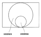
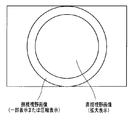
例えば、日本国特開2008-309860号公報には、中心軸方向に相当する直視方向の被写体像と、該中心軸方向に対して略直交する側視方向の全方位の被写体像と、を同時に取得可能な光学系、及び、該光学系を備えた内視鏡が開示されている。そして、日本国特開2008-309860号公報に開示された光学系を備えた内視鏡によれば、円形形状をなす直視方向の画像(直視視野画像)と、該直視方向の画像の外周において円環形状をなす側視方向の全周の画像(側視視野画像)と、がモニタ等の表示部に表示される。
しかし、日本国特開2008-309860号公報に開示された光学系を備えた内視鏡によれば、前述したような表示態様をとることにより、個々の視野方向の画像の表示サイズを、従来の直視型内視鏡または側視型内視鏡に比べて小さなサイズにせざるを得ないため、結果的に、視認性が低下した画像が表示されてしまう、という課題が生じている。
本発明は、前述した事情に鑑みてなされたものであり、直視方向と側視方向とを同時に観察可能であるとともに、一方の視野方向の画像における視認性を向上させることが可能な内視鏡システムを提供することを目的としている。
本発明の内視鏡システムは、観察対象物の直視視野画像及び側視視野画像を取得する内視鏡と、所定の出力信号または所定の出力情報に基づいて所定の検出結果を取得する検出部と、前記直視視野画像と前記側視視野画像とを同一の画面内に具備する観察画像を生成し、前記所定の検出結果に基づき、前記直視視野画像及び前記側視視野画像のうちの一方の視野画像を表示部において拡大表示させ、かつ、他方の視野画像の前記表示部における表示態様を変化させる処理を行う画像処理部と、を有する。
以下、本発明の実施の形態について、図面を参照しつつ説明を行う。
(第1の実施例)
図1に示すように、内視鏡システム1は、観察対象物を撮像して撮像信号を出力する内視鏡2と、該観察対象物を照明するための照明光を供給する光源装置31と、該撮像信号に応じた映像信号を生成及び出力するビデオプロセッサ32と、該映像信号に応じた観察画像を表示するモニタ35と、を有している。
図1に示すように、内視鏡システム1は、観察対象物を撮像して撮像信号を出力する内視鏡2と、該観察対象物を照明するための照明光を供給する光源装置31と、該撮像信号に応じた映像信号を生成及び出力するビデオプロセッサ32と、該映像信号に応じた観察画像を表示するモニタ35と、を有している。
内視鏡2は、術者が把持して操作を行う操作部3と、操作部3の先端側に形成され、体腔内等に挿入される細長の挿入部4と、操作部3の側部から延出するように一方の端部が設けられたユニバーサルコード5と、を有して構成されている。
挿入部4は、最も先端側に設けられた硬質の先端部6と、先端部6の後端に設けられた湾曲自在の湾曲部7と、湾曲部7の後端に設けられた長尺かつ可撓性を有する可撓管部8と、を有して構成されている。また、湾曲部7は、操作部3に設けられた湾曲操作レバー9の操作に応じた湾曲動作を行う。
挿入部4は、最も先端側に設けられた硬質の先端部6と、先端部6の後端に設けられた湾曲自在の湾曲部7と、湾曲部7の後端に設けられた長尺かつ可撓性を有する可撓管部8と、を有して構成されている。また、湾曲部7は、操作部3に設けられた湾曲操作レバー9の操作に応じた湾曲動作を行う。
一方、図2に示すように、挿入部4の先端部6には、先端部6の先端面の中央から上方寄りに偏心した位置から突出して設けられた、円柱形状の円筒部10が形成されている。
円筒部10の先端部には、直視及び側視を兼ねる図示しない対物光学系が設けられている。また、円筒部10の先端部は、前記図示しない対物光学系の直視方向に相当する箇所に配置された直視観察窓12と、前記図示しない対物光学系の側視方向に相当する箇所に配置された側視観察窓13と、を有して構成されている。さらに、円筒部10の基端付近には、側視方向を照明するための光を出射する側視照明部14が形成されている。
側視観察窓13は、円柱形状の円筒部10における周方向から入射される観察対象物からの戻り光(反射光)を側視視野内に捉えることにより側視視野画像を取得可能とするための、側視用ミラーレンズ15を備えている。
なお、前記図示しない対物光学系の結像位置には、直視観察窓12の視野内の観察対象物の画像が円形の直視視野画像として中央部に形成され、かつ、側視観察窓13の視野内の観察対象物の画像が円環形状の側視視野画像として該直視視野画像の外周部に形成されるように、撮像素子(の撮像面)が配置されているものとする。
先端部6の先端面には、円筒部10に隣接する位置に配置され、直視観察窓12の直視視野の範囲に照明光を出射する直視照明窓16と、挿入部4内に配設されたチューブ等により形成された図示しない処置具チャンネルに連通するとともに、該処置具チャンネルに挿通された処置具(の先端部)を突出させることが可能な先端開口部17と、が設けられている。
また、挿入部4の先端部6は、先端部6の先端面から突出するように設けられた支持部18を有し、この支持部18は円筒部10の下部側に隣接して位置する。
支持部18は、先端部6の先端面から突出されるように配置された各突出部材を支持(または保持)可能に構成されている。具体的には、支持部18は、前述の各突出部材としての、直視観察窓12を洗浄するための気体または液体を射出する直視観察窓用ノズル部19と、直視方向を照明するための光を出射する直視照明窓21と、側視観察窓13を洗浄するための気体または液体を射出する側視観察窓用ノズル部22と、をそれぞれ支持(または保持)可能に構成されている。
一方、支持部18は、本来の観察対象物とは異なる物体である前述の各突出部材が側視視野内に現れることにより、該各突出部材のいずれかを含むような側視視野画像を取得してしまわないようにするための、光学的な遮蔽部材である遮蔽部18aを有して形成されている。すなわち、遮蔽部18aを支持部18に設けることにより、直視観察窓用ノズル部19、直視照明窓21、及び、側視観察窓用ノズル部22がいずれも含まれないような側視視野画像を得ることができる。
側視観察窓用ノズル部22は、図2及び図3に示すように、支持部18の2箇所に設けられているとともに、支持部18の側面に先端が突出するように配置されている。
操作部3には、図1に示すように、直視観察窓12を洗浄するための気体または液体を直視観察窓用ノズル部19から射出させる操作指示が可能な送気送液操作ボタン24aと、側視観察窓13を洗浄するための気体または液体を側視観察窓用ノズル部22から射出させる操作指示が可能な送気送液操作ボタン24bと、が設けられ、この送気送液操作ボタン24a及び24bの押下により送気と送液とが切り替え可能である。また、本実施例ではそれぞれのノズル部に対応するように複数の送気送液操作ボタンを設けているが、例えば一つの送気送液操作ボタンの操作により直視観察窓用ノズル部19、側視観察窓用ノズル部22の両方から気体または液体が射出されるようにしてもよい。
スコープスイッチ25は、操作部3の頂部に複数設けられており、内視鏡2において使用可能な種々の機能のオンまたはオフ等に対応した信号を出力させるように、各スイッチ毎の機能を割り付けることが可能な構成を有している。具体的には、スコープスイッチ25には、例えば、前方送水の開始及び停止、フリーズの実行及び解除、及び、処置具の使用状態の告知等に対応した信号を出力させる機能を、各スイッチ毎の機能として割り付けることができる。
なお、本実施例においては、送気送液操作ボタン24a及び24bのうちの少なくともいずれか一方の機能を、スコープスイッチ25のうちのいずれかに割り付けるようにしても良い。
また、操作部3には、体腔内の粘液等を先端開口部17より吸引して回収するための指示を図示しない吸引ユニット等に対して行うことが可能な吸引操作ボタン26が配設されている。
そして、図示しない吸引ユニット等の動作に応じて吸引された体腔内の粘液等は、先端開口部17と、挿入部4内の図示しない処置具チャンネルと、操作部3の前端付近に設けられた処置具挿入口27とを経た後、図示しない吸引ユニットの吸引ボトル等に回収される。
処置具挿入口27は、挿入部4内の図示しない処置具チャンネルに連通しているとともに、図示しない処置具を挿入可能な開口として形成されている。すなわち、術者は、処置具挿入口27から処置具を挿入し、該処置具の先端側を先端開口部17から突出させることにより、該処置具を用いた処置を行うことができる。
一方、図1に示すように、ユニバーサルコード5の他方の端部には、光源装置31に接続可能なコネクタ29が設けられている。
コネクタ29の先端部には、流体管路の接続端部となる口金(図示せず)と、照明光の供給端部となるライトガイド口金(図示せず)とが設けられている。また、コネクタ29の側面には、接続ケーブル33の一方の端部を接続可能な電気接点部(図示せず)が設けられている。さらに、接続ケーブル33の他方の端部には、内視鏡2とビデオプロセッサ32と電気的に接続するためのコネクタが設けられている。
ユニバーサルコード5には、種々の電気信号を伝送するための複数の信号線、及び、光源装置31から供給される照明光を伝送するためのライトガイドが束ねられた状態として内蔵されている。
挿入部4からユニバーサルコード5にかけて内蔵された前記ライトガイドは、光出射側の端部が挿入部4付近において少なくとも2方向に分岐されるとともに、一方の側の光出射端面が直視照明窓16及び21に配置され、かつ、他方の側の光出射端面が側視照明部14に配置されるような構成を有している。また、前記ライトガイドは、光入射側の端部がコネクタ29のライトガイド口金に配置されるような構成を有している。
ビデオプロセッサ32は、内視鏡2の先端部6に設けられた撮像素子を駆動するための駆動信号を出力する。そして、ビデオプロセッサ32は、前記撮像素子から出力される撮像信号に対して信号処理を施すことにより、映像信号を生成してモニタ35へ出力する。これにより、円形形状をなす直視視野画像と、該直視方向の画像の外周において円環形状をなす側視視野画像とを具備した観察画像が、例えば図4に示すような態様によりモニタ35に表示される。なお、本実施例及び以降の実施例において示される観察画像においては、支持部18の遮蔽部18aにより光学的に遮蔽される部分を考慮しないものとする。 一方、ビデオプロセッサ32は、スコープスイッチ25から出力される信号に基づき、該信号に応じた一の機能がオンまたはオフされたことを(後述する操作検出部32bにおいて)検出することができる。
また、ビデオプロセッサ32は、後程詳述する種々の要因に基づき、前記直視視野画像と前記側視視野画像とを同一の画面内に具備する観察画像の表示態様を変化させるような画像処理を行う。
光源装置31、ビデオプロセッサ32及びモニタ35等の周辺装置は、患者情報の入力等を行うキーボード34とともに、架台36に配置されている。
次に、本実施例の作用について説明を行う。
次に、本実施例の作用について説明を行う。
まず、図5に要部を示した内視鏡システム1において、内視鏡2の先端部6に設けられた撮像素子51、ビデオプロセッサ32及びモニタ35の各部が起動されることにより、撮像素子51から撮像信号が出力される。
ビデオプロセッサ32の画像処理部32a(図5参照)は、撮像素子51から出力される撮像信号に対して信号処理を施すことにより、映像信号を生成してモニタ35へ出力する。これにより、モニタ35には、例えば図4に示すような観察画像が表示される。
一方、術者は、所望の処置具を用いた処置を行うために、処置具挿入口27から該所望の処置具を挿入し、該所望の処置具の先端側を先端開口部17から突出させる。これに伴い、術者は、前記所望の処置具を処置具挿入口27から挿入した後、前記所望の処置具の先端側を先端開口部17から突出させて実際の処置を行うまでの期間のいずれかにおいて、スコープスイッチ25を操作することにより、前記所望の処置具を用いた処置を行う旨をビデオプロセッサ32に対して告知するための処置具使用告知信号を出力させる。
なお、前記処置具使用告知信号は、スコープスイッチ25の操作に応じて出力されるものに限らず、例えば、先端開口部17の近辺、及び、処置具挿入口27の近辺のうちの少なくともいずれか一方に設けた光センサからの出力信号として出力されるものであっても良い。
ビデオプロセッサ32の操作検出部32b(図5参照)は、スコープスイッチ25から出力される処置具使用告知信号に基づき、内視鏡2において処置具が用いられていることを検出し、検出結果を画像処理部32aへ出力する。
画像処理部32aは、内視鏡2において処置具が用いられているとの検出結果が操作検出部32bから出力された場合に、直視視野画像を拡大する(モニタ35における表示サイズを大きくする)処理を行うとともに、直視視野画像の拡大に応じて側視視野画像の表示態様を変化させる画像処理を行う。
具体的には、側視視野画像の表示態様を変化させる前記画像処理は、例えば、図15のような側視視野画像の元画像に対し、拡大された直視視野画像に隣接する範囲(元画像の中央側)のみをモニタ35に表示させるもの(図16)であっても良く、拡大された直視視野画像に覆われない範囲(元画像の外縁側)のみをモニタ35に表示させるもの(図17)であっても良い。または、側視視野画像の表示態様を変化させる前記画像処理は、例えば、側視視野画像の元画像の視野範囲を維持しつつ、該元画像に対して画像圧縮処理を施した圧縮画像をモニタ35に表示させるもの(図18)であっても良い。
そして、画像処理部32aは、以上に述べた処理を直視視野画像及び側視視野画像に対してそれぞれ施すことにより、例えば図13に示すような表示態様の観察画像を生成してモニタ35へ出力する。図13に例示した観察画像においては、直視視野画像の拡大表示に伴い、側視視野画像の元画像の一部に相当する画像、または、側視視野画像の元画像を圧縮した画像が表示される。
ここで、処置具を用いた内視鏡検査を行う場合においては、直視方向の患部へ向かうように処置具を突出させる手法が一般的である。そして、図13に示すような表示態様を具備する観察画像によれば、拡大された直視視野画像を見ながら、処置具を直視方向に突出させて患部に近づけるという一連の操作をスムーズに行うことができる。
なお、本実施例においては、処置具を用いた処置を行う場合に直視視野画像が拡大表示される(図13に示すような表示態様の観察画像が生成される)ものに限らず、例えば、前方送水の開始を指示するための信号がスコープスイッチ25から出力された場合に直視視野画像が拡大表示される(図13に示すような表示態様の観察画像が生成される)ものであっても良い。
以上に述べたように、本実施例によれば、処置具の使用状態及びスコープスイッチの操作状態のうちの少なくとも一方に応じ、直視方向と側視方向とを同時に観察可能な観察画像における一方の視野方向の画像の視認性を向上させることができる。
また、本実施例の変形例として、湾曲操作レバー9において湾曲部7の湾曲操作がなされた場合に、前述したものとは異なる表示態様の観察画像が生成及び出力されるように構成しても良い。
このような場合、例えば図6に示すように、ビデオプロセッサ32の操作検出部32bは、湾曲操作レバー9の操作状態に基づいて湾曲部7の湾曲方向を検出し、検出結果を画像処理部32aへ出力する。
画像処理部32aは、湾曲部7の湾曲方向に係る検出結果が操作検出部32bから出力された場合に、図4に例示した観察画像の表示態様を、該湾曲方向に対応した他の表示態様へ遷移させる画像処理を行う。
観察画像の表示態様を湾曲部7の湾曲方向に対応した他の表示態様へ遷移させる前記画像処理としては、例えば、該湾曲方向に対応する側視視野画像の視野範囲を拡大するとともに、直視視野画像を該湾曲方向の反対の方向へ移動させるような第1の処理を用いることができる。
前述の第1の処理によれば、例えば湾曲部7が上方向に湾曲していることが検出された場合、画像処理部32aは、側視視野画像の上部の視野範囲を拡大するとともに、直視視野画像を観察画像の下部へ移動させる。これにより、モニタ35に表示される観察画像が、図4に示すものから図7に示すものへ遷移する。
なお、本実施例においては、前述の第1の処理により観察画像が図4に示すものから図7に示すものへ遷移した場合であっても、直視視野画像の視野範囲は維持されるものとする。また、前述の第1の処理は、湾曲部7が上方向に湾曲された場合のみに限らず、湾曲部7が上方向以外の他の方向へ湾曲された場合においても略同様に適用されるものとする。
一方、観察画像の表示態様を湾曲部7の湾曲方向に対応した他の表示態様へ遷移させる前記画像処理としては、前述の第1の処理の代わりに、例えば、該湾曲方向に対応する観察画像の一部を抽出して拡大するような第2の処理を用いることもできる。
前述の第2の処理によれば、例えば湾曲部7が上方向に湾曲していることが検出された場合、画像処理部32aは、図4に示す観察画像の上半分を抽出して拡大する。これにより、モニタ35に表示される観察画像が、図4に示すものから図8に示すものへ遷移する。
なお、前述の第2の処理は、湾曲部7が上方向に湾曲された場合のみに限らず、湾曲部7が上方向以外の他の方向へ湾曲された場合においても略同様に適用されるものとする。
以上に述べたように、本実施例の変形例によれば、直視方向と側視方向とを同時に観察可能な観察画像において、該観察画像の表示態様を湾曲部の湾曲方向に応じて適宜遷移させることができるため、湾曲操作時の視認性を向上させることができる。
(第2の実施例)
次に、本発明の第2の実施例について説明する。
次に、本発明の第2の実施例について説明する。
なお、以降の説明において、第1の実施例と同様の構成を持つ部分については、詳細な説明を省略する。また、本実施例の内視鏡システムは、第1の実施例において、図1から図3までに示した外観構成、及び、図4に示した表示態様をそれぞれ踏襲している一方、図5に示した要部の構成とは一部異なる構成要素を具備している。そのため、本実施例においては、図5に示した要部の構成と異なる部分について主に説明を行うものとする。
まず、図9に要部を示した内視鏡システム101において、内視鏡102の先端部6に設けられた撮像素子51、光源装置31、ビデオプロセッサ132及びモニタ35の各部が起動されることにより、撮像素子51から撮像信号が出力される。
ビデオプロセッサ132の画像処理部32aは、撮像素子51から出力される撮像信号に対して信号処理を施すことにより、映像信号を生成してモニタ35へ出力する。これにより、モニタ35には、例えば図4に示すような観察画像が表示される。
一方、術者は、内視鏡102の挿入部4を体腔内において適宜挿入または抜去することにより、該体腔内の所望の部位に先端部6を接近させる。
内視鏡102の先端部6またはその付近には、挿入部4の移動方向に関する情報を物理量として検出及び信号出力することが可能なセンサ161(図9参照)が設けられている。具体的には、センサ161は、挿入部4の位置の時間的な変位を加速度として検出及び出力可能な加速度センサ、または、挿入部4の位置の単位時間あたりの変位量(移動量)を検出及び出力可能な光センサ等により構成されている。
また、内視鏡102の挿入部4のセンサ161の後段には、センサ161において検出された情報を電気信号に変換してビデオプロセッサ132へ出力することが可能なエンコーダ162(図9参照)が設けられている。
ビデオプロセッサ132の挿抜検出部132b(図9参照)は、エンコーダ162から出力される電気信号に基づき、挿入部4の移動方向が前方(挿入方向)または後方(抜去方向)のいずれであるかを検出し、検出結果を画像処理部32aへ出力する。
画像処理部32aは、挿入部4が前方(挿入方向)に移動しているとの検出結果が挿抜検出部132bから出力された場合に、直視視野画像を拡大する(モニタ35における表示サイズを大きくする)処理を行うとともに、直視視野画像の拡大に応じて側視視野画像の表示態様を変化させる画像処理を行う。
具体的には、側視視野画像の表示態様を変化させる前記画像処理は、例えば、側視視野画像の元画像のうち、拡大された直視視野画像に隣接する範囲(元画像の中央側)のみをモニタ35に表示させるものであっても良く、拡大された直視視野画像に覆われない範囲(元画像の外縁側)のみをモニタ35に表示させるものであっても良い。または、側視視野画像の表示態様を変化させる前記画像処理は、例えば、側視視野画像の元画像の視野範囲を維持しつつ、該元画像に対して画像圧縮処理を施した圧縮画像をモニタ35に表示させるものであっても良い。
そして、画像処理部32aは、以上に述べた処理を直視視野画像及び側視視野画像に対してそれぞれ施すことにより、例えば図13に示すような表示態様の観察画像を生成してモニタ35へ出力する。図13に例示した観察画像においては、直視視野画像の拡大表示に伴い、側視視野画像の元画像の一部に相当する画像、または、側視視野画像の元画像を圧縮した画像が表示される。
ここで、挿入部の挿入操作においては、主に直視方向に対する注意を要するような状況が多く生じ得る。そして、図13に示すような表示態様を具備する観察画像によれば、拡大された直視視野画像を見ながら、挿入部4の挿入操作をスムーズに行うことができる。
また、画像処理部32aは、挿入部4が後方(抜去方向)に移動しているとの検出結果が挿抜検出部132bから出力された場合に、側視視野画像を拡大する(モニタ35における表示サイズを大きくする)処理を行うとともに、側視視野画像の拡大に応じて直視視野画像の表示態様を変化させる画像処理を行う。
具体的には、直視視野画像の表示態様を変化させる前記画像処理は、例えば、直視視野画像の元画像のうち、拡大された側視視野画像に隣接する範囲(元画像の外縁側)のみをモニタ35に表示させるものであっても良く、拡大された直視視野画像に覆われない範囲(元画像の中央側)のみをモニタ35に表示させるものであっても良い。または、直視視野画像の表示態様を変化させる前記画像処理は、例えば、直視視野画像の元画像の視野範囲を維持しつつ、該元画像に対して画像圧縮処理を施した圧縮画像をモニタ35に表示させるものであっても良い。
そして、画像処理部32aは、以上に述べた処理を直視視野画像及び側視視野画像に対してそれぞれ施すことにより、例えば図14に示すような表示態様の観察画像を生成してモニタ35へ出力する。図14に例示した観察画像においては、側視視野画像の拡大表示に伴い、直視視野画像の元画像の一部に相当する画像、または、直視視野画像の元画像を圧縮した画像が表示される。
なお、本実施例の画像処理部32aは、図14に例示した表示態様を具備し、かつ、挿入部4の挿入軸方向に対する後方視野50°を含む全体視野が230°となるように観察画像を生成するものであっても良い。
ここで、挿入部の抜去操作においては、主に側視方向に対する注意を要するような状況が多く生じ得る。そして、図14に示すような表示態様を具備する観察画像によれば、拡大された側視視野画像を見ながら、挿入部4の抜去操作をスムーズに行うことができる。
なお、本実施例によれば、センサ161及びエンコーダ162を具備して構成される図9の内視鏡システム101の代わりに、例えば、挿入形状取得装置163を用いて内視鏡2の挿入部4の移動方向に関する情報を取得する、図10の内視鏡システム101Aのように構成されるものであっても良い。
具体的には、図10に要部を示した内視鏡システム101Aの挿入形状取得装置163は、例えば、挿入部4のX線画像を取得して挿抜検出部132bへ信号出力することが可能な、X線撮像装置として構成される。この場合、挿抜検出部132bは、例えば、挿入形状取得装置163から順次信号出力される挿入部4のX線画像のうち、時系列的に隣接する2枚のX線画像を比較することにより、挿入部4の移動方向が前方(挿入方向)または後方(抜去方向)のいずれであるかを検出し、検出結果を画像処理部32aへ出力する。
または、挿入形状取得装置163は、例えば、挿入部4に配置された複数の磁界発生素子(図示せず)の駆動に応じて発生した磁界を磁界検出部(図示せず)において検出するとともに、該磁界に応じた挿入部4の挿入形状画像を生成して挿抜検出部132bへ信号出力することが可能な、内視鏡挿入形状検出装置として構成される。この場合、挿抜検出部132bは、例えば、挿入形状取得装置163から順次信号出力される挿入部4の挿入形状画像のうち、時系列的に隣接する2枚の挿入形状画像を比較することにより、挿入部4の移動方向が前方(挿入方向)または後方(抜去方向)のいずれであるかを検出し、検出結果を画像処理部32aへ出力する。
以上に述べたように、本実施例によれば、内視鏡の挿入部の挿入操作及び抜去操作に応じ、直視方向と側視方向とを同時に観察可能な観察画像における一方の視野方向の画像の視認性を向上させることができる。
(第3の実施例)
次に、本発明の第3の実施例について説明する。
次に、本発明の第3の実施例について説明する。
なお、以降の説明において、第1の実施例または第2の実施例と同様の構成を持つ部分については、詳細な説明を省略する。また、本実施例の内視鏡システムは、第1の実施例において、図1から図3までに示した外観構成、及び、図4に示した表示態様をそれぞれ踏襲している一方、図5に示した要部の構成とは一部異なる構成要素を具備している。そのため、本実施例においては、図5に示した要部の構成と異なる部分について主に説明を行うものとする。
まず、図11に要部を示した内視鏡システム201において、内視鏡2の先端部6に設けられた撮像素子51、光源装置31、ビデオプロセッサ232及びモニタ35の各部が起動されることにより、撮像素子51から撮像信号が出力される。
ビデオプロセッサ232の画像処理部32aは、撮像素子51から出力される撮像信号に対して信号処理を施すことにより、映像信号を生成して画像解析部232b(図11参照)及びモニタ35へ出力する。これにより、モニタ35には、例えば図4に示すような観察画像が表示される。
ビデオプロセッサ232の画像解析部232bは、画像処理部32aから出力される映像信号に応じた観察画像において、所定の色を具備する対象物、または、所定の輝度を具備する対象物をランドマークとするように予め設定されている。
また、画像解析部232bは、例えば、時系列的に隣接する2フレーム分の観察画像を比較することにより、前述のランドマークが観察画像の外縁側または中央側のどちらに向かって移動しているかを検出し、検出結果を画像処理部32aへ出力する。具体的には、画像解析部232bは、例えば、観察画像内の輝度の空間的勾配または時間的勾配(オプティカルフロー)を用いた演算を行うことにより前述のランドマークの移動方向を検出し、検出結果を画像処理部32aへ出力する。
画像処理部32aは、前述のランドマークが観察画像の外縁側に移動しているとの検出結果が画像解析部232bから出力された場合に、(挿入部4が挿入されていると推定されるため、)直視視野画像を拡大する(モニタ35における表示サイズを大きくする)処理を行うとともに、直視視野画像の拡大に応じて側視視野画像の表示態様を変化させる画像処理を行う。
具体的には、側視視野画像の表示態様を変化させる前記画像処理は、例えば、側視視野画像の元画像のうち、拡大された直視視野画像に隣接する範囲(元画像の中央側)のみをモニタ35に表示させるものであっても良く、拡大された直視視野画像に覆われない範囲(元画像の外縁側)のみをモニタ35に表示させるものであっても良い。または、側視視野画像の表示態様を変化させる前記画像処理は、例えば、側視視野画像の元画像の視野範囲を維持しつつ、該元画像に対して画像圧縮処理を施した圧縮画像をモニタ35に表示させるものであっても良い。
そして、画像処理部32aは、以上に述べた処理を直視視野画像及び側視視野画像に対してそれぞれ施すことにより、例えば図13に示すような表示態様の観察画像を生成してモニタ35へ出力する。図13に例示した観察画像においては、直視視野画像の拡大表示に伴い、側視視野画像の元画像の一部に相当する画像、または、側視視野画像の元画像を圧縮した画像が表示される。
ここで、挿入部の挿入操作においては、主に直視方向に対する注意を要するような状況が多く生じ得る。そして、図13に示すような表示態様を具備する観察画像によれば、拡大された直視視野画像を見ながら、挿入部4の挿入操作をスムーズに行うことができる。
また、画像処理部32aは、前述のランドマークが観察画像の中央側に移動しているとの検出結果が画像解析部232bから出力された場合に、(挿入部4が抜去されていると推定されるため、)側視視野画像を拡大する(モニタ35における表示サイズを大きくする)処理を行うとともに、側視視野画像の拡大に応じて直視視野画像の表示態様を変化させる画像処理を行う。
具体的には、直視視野画像の表示態様を変化させる前記画像処理は、例えば、直視視野画像の元画像のうち、拡大された側視視野画像に隣接する範囲(元画像の外縁側)のみをモニタ35に表示させるものであっても良く、拡大された直視視野画像に覆われない範囲(元画像の中央側)のみをモニタ35に表示させるものであっても良い。または、直視視野画像の表示態様を変化させる前記画像処理は、例えば、直視視野画像の元画像の視野範囲を維持しつつ、該元画像に対して画像圧縮処理を施した圧縮画像をモニタ35に表示させるものであっても良い。
そして、画像処理部32aは、以上に述べた処理を直視視野画像及び側視視野画像に対してそれぞれ施すことにより、例えば図14に示すような表示態様の観察画像を生成してモニタ35へ出力する。図14に例示した観察画像においては、側視視野画像の拡大表示に伴い、直視視野画像の元画像の一部に相当する画像、または、直視視野画像の元画像を圧縮した画像が表示される。
なお、本実施例の画像処理部32aは、図14に例示した表示態様を具備し、かつ、挿入部4の挿入軸方向に対する後方視野50°を含む全体視野が230°となるように観察画像を生成するものであっても良い。
ここで、挿入部の抜去操作においては、主に側視方向に対する注意を要するような状況が多く生じ得る。そして、図14に示すような表示態様を具備する観察画像によれば、拡大された側視視野画像を見ながら、挿入部4の抜去操作をスムーズに行うことができる。
なお、画像解析部232bは、前述のランドマークが観察画像の外縁側または中央側のいずれかに移動しているという検出結果以外に、前述のランドマークが移動していないとの検出結果を出力するものであっても良い。これに応じ、画像処理部32aは、前述のランドマークが移動していないとの検出結果を画像解析部232bから得た場合において、(挿入部4が移動していないと推定されるため、)観察画像の表示態様を前回と同じ表示態様に維持するものであっても良い。
また、本実施例の画像解析部232bは、前述のランドマークが観察画像の外縁側または中央側のどちらに向かって移動しているかを検出するものに限らず、例えば、時系列的に隣接する2フレーム分の観察画像を比較することにより、観察画像内における前述のランドマークの大きさの経時的変化を検出するものであっても良い。これに応じ、画像処理部32aは、前述のランドマークの大きさが次第に大きくなっているとの検出結果を画像解析部232bから得た場合に図13に例示した観察画像を生成し、前述のランドマークの大きさが次第に小さくなっているとの検出結果を画像解析部232bから得た場合に図14に例示した観察画像を生成し、さらに、前述のランドマークの大きさが変化していないとの検出結果を画像解析部232bから得た場合に(挿入部4が移動していないと推定されるため、)観察画像の表示態様を前回と同じ表示態様に維持するものであっても良い。
さらに、例えば図19に示すように、管腔内を観察する場合、管腔に挿入された挿入部の進行方向奥側(開口方向深部)は、観察用の照明光が届き難いことから、画像上は暗部として表示される。本実施例の画像解析部232bは、これを利用し、画像上の暗部をランドマークとして設定することで、暗部(管腔に挿入された挿入部4の進行方向)が現在の観察画像における直視視野画像または側視視野画像のどちらに位置するかを検出するものであっても良い。これに応じ、画像処理部32aは、暗部が直視視野画像内に存在するとの検出結果を画像解析部232bから得た場合に図13に例示した観察画像を生成し、暗部が側視視野画像内に存在するとの検出結果を画像解析部232bから得た場合に図14に例示した観察画像を生成するものであっても良い。
以上に述べたように、本実施例によれば、内視鏡の現在の観察状況に応じ、直視方向と側視方向とを同時に観察可能な観察画像における一方の視野方向の画像の視認性を向上させることができる。
(第4の実施例)
次に、本発明の第4の実施例について説明する。
次に、本発明の第4の実施例について説明する。
なお、以降の説明において、第1の実施例、第2の実施例または第3の実施例と同様の構成を持つ部分については、詳細な説明を省略する。また、本実施例の内視鏡システムは、第1の実施例において、図1から図3までに示した外観構成、及び、図4に示した表示態様をそれぞれ踏襲している一方、図5に示した要部の構成とは一部異なる構成要素を具備している。そのため、本実施例においては、図5に示した要部の構成と異なる部分について主に説明を行うものとする。
まず、図12に要部を示した内視鏡システム301において、内視鏡2の先端部6に設けられた撮像素子51、光源装置31、ビデオプロセッサ332及びモニタ35の各部が起動されることにより、撮像素子51から撮像信号が出力される。
ビデオプロセッサ332の画像処理部32aは、撮像素子51から出力される撮像信号に対して信号処理を施すことにより、映像信号を生成してモニタ35へ出力する。これにより、モニタ35には、例えば図4に示すような観察画像が表示される。
術者は、指示入力装置364に対する入力操作により、モニタ35に表示される観察画像のうち、直視視野画像または側視視野画像の一方を拡大するための指示を行う。なお、指示入力装置364は、単体の装置として構成されたものであっても良く、または、内視鏡システム301が具備するいずれかの装置に組み込まれたものであっても良い。具体的には、指示入力装置364は、スコープスイッチ25、キーボード34、ビデオプロセッサ332の操作パネル、または、フットスイッチのいずれであっても良い。
ビデオプロセッサ332の指示入力検出部332bは、指示入力装置364においてなされた指示が、直視視野画像を拡大するための指示、または、側視視野画像を拡大するための指示のいずれであるかを検出し、検出結果を画像処理部32aへ出力する。
画像処理部32aは、直視視野画像を拡大するための指示がなされたとの検出結果が指示入力検出部332bから出力された場合に、直視視野画像を拡大する(モニタ35における表示サイズを大きくする)処理を行うとともに、直視視野画像の拡大に応じて側視視野画像の表示態様を変化させる画像処理を行う。
具体的には、側視視野画像の表示態様を変化させる前記画像処理は、例えば、側視視野画像の元画像のうち、拡大された直視視野画像に隣接する範囲(元画像の中央側)のみをモニタ35に表示させるものであっても良く、拡大された直視視野画像に覆われない範囲(元画像の外縁側)のみをモニタ35に表示させるものであっても良い。または、側視視野画像の表示態様を変化させる前記画像処理は、例えば、側視視野画像の元画像の視野範囲を維持しつつ、該元画像に対して画像圧縮処理を施した圧縮画像をモニタ35に表示させるものであっても良い。
そして、画像処理部32aは、以上に述べた処理を直視視野画像及び側視視野画像に対してそれぞれ施すことにより、例えば図13に示すような表示態様の観察画像を生成してモニタ35へ出力する。図13に例示した観察画像においては、直視視野画像の拡大表示に伴い、側視視野画像の元画像の一部に相当する画像、または、側視視野画像の元画像を圧縮した画像が表示される。
また、画像処理部32aは、側視視野画像を拡大するための指示がなされたとの検出結果が指示入力検出部332bから出力された場合に、側視視野画像を拡大する(モニタ35における表示サイズを大きくする)処理を行うとともに、側視視野画像の拡大に応じて直視視野画像の表示態様を変化させる画像処理を行う。
具体的には、直視視野画像の表示態様を変化させる前記画像処理は、例えば、直視視野画像の元画像のうち、拡大された側視視野画像に隣接する範囲(元画像の外縁側)のみをモニタ35に表示させるものであっても良く、拡大された直視視野画像に覆われない範囲(元画像の中央側)のみをモニタ35に表示させるものであっても良い。または、直視視野画像の表示態様を変化させる前記画像処理は、例えば、直視視野画像の元画像の視野範囲を維持しつつ、該元画像に対して画像圧縮処理を施した圧縮画像をモニタ35に表示させるものであっても良い。
そして、画像処理部32aは、以上に述べた処理を直視視野画像及び側視視野画像に対してそれぞれ施すことにより、例えば図14に示すような表示態様の観察画像を生成してモニタ35へ出力する。図14に例示した観察画像においては、側視視野画像の拡大表示に伴い、直視視野画像の元画像の一部に相当する画像、または、直視視野画像の元画像を圧縮した画像が表示される。
なお、本実施例の画像処理部32aは、図14に例示した表示態様を具備し、かつ、挿入部4の挿入軸方向に対する後方視野50°を含む全体視野が230°となるように観察画像を生成するものであっても良い。
また、指示入力装置364は、前述した各装置により構成されるものに限らず、例えば、術者の声を音声信号として取り込むことが可能なマイクにより構成されるものであっても良い。これに応じ、指示入力検出部332bは、指示入力装置364から出力される音声信号に対して音声解析処理を行うことにより、直視視野画像を拡大するための指示、または、側視視野画像を拡大するための指示のいずれがなされたかを検出するものであっても良い。
また、本実施例においては、直視視野画像を拡大するための指示、及び、側視視野画像を拡大するための指示に加え、観察画像の表示態様を図4に例示したものへ戻すための指示を行うことができるように指示入力装置364を構成しても良い。
以上に述べたように、本実施例によれば、直視方向と側視方向とを同時に観察可能な観察画像において、所望の一方の視野方向の視認性を向上させるような表示態様とすることができる。また、本実施例の指示入力装置364の入力操作による表示態様の切替制御を、実施例1~3にあるような自動表示態様切替制御と組み合わせて用いてもよい。このような場合には、例えば自動切替制御よりも指示入力装置364の入力操作による切替を優先することにより、術者の意図に応じた所望の表示態様を選択することができる。
なお、本発明は、上述した各実施例に限定されるものではなく、発明の趣旨を逸脱しない範囲内において種々の変更や応用が可能であることは勿論である。
本出願は、2009年11月6日に日本国に出願された特願2009-255186号を優先権主張の基礎として出願するものであり、上記の開示内容は、本願明細書、請求の範囲、図面に引用されたものとする。
Claims (18)
- 観察対象物の直視視野画像及び側視視野画像を取得する内視鏡と、
所定の出力信号または所定の出力情報に基づいて所定の検出結果を取得する検出部と、
前記直視視野画像と前記側視視野画像とを同一の画面内に具備する観察画像を生成し、前記所定の検出結果に基づき、前記直視視野画像及び前記側視視野画像のうちの一方の視野画像を表示部において拡大表示させ、かつ、他方の視野画像の前記表示部における表示態様を変化させる処理を行う画像処理部と、
を有することを特徴とする内視鏡システム。 - 前記画像処理部は、前記他方の視野画像の前記表示部における表示態様を変化させるための処理として、前記他方の視野画像の一部のみを前記表示部に表示させるための処理を行うことを特徴とする請求項1に記載の内視鏡システム。
- 前記画像処理部は、前記他方の視野画像の前記表示部における表示態様を変化させるための処理として、前記他方の視野画像の圧縮画像を前記表示部に表示させるための画像圧縮処理を行うことを特徴とする請求項1に記載の内視鏡システム。
- 前記検出部は、前記内視鏡に処置具が挿通された際に出力される告知信号に基づき、前記内視鏡において処置具が用いられていることを検出することを特徴とする請求項1乃至請求項3のいずれか一項に記載の内視鏡システム。
- 前記内視鏡は、前記内視鏡において使用可能な機能に対応した信号を出力するためのスイッチを1または複数有し、
前記検出部は、前記スイッチから出力される信号に基づき、該信号に応じた一の機能がオンまたはオフされたことを検出することを特徴とする請求項1乃至請求項3のいずれか一項に記載の内視鏡システム。 - 前記画像処理部は、前記内視鏡の挿入部が挿入されているという検出結果が前記検出部において得られた場合に、前記直視視野画像を前記表示部において拡大表示させるための処理を行うことを特徴とする請求項1乃至請求項3のいずれか一項に記載の内視鏡システム。
- 前記画像処理部は、前記内視鏡の挿入部が抜去されているという検出結果が前記検出部において得られた場合に、前記側視視野画像を前記表示部において拡大表示させるための処理を行うことを特徴とする請求項1乃至請求項3のいずれか一項に記載の内視鏡システム。
- 前記検出部は、前記挿入部の移動方向に関する情報としての物理量を含む信号に基づき、前記挿入部が挿入されていることを検出することを特徴とする請求項6に記載の内視鏡システム。
- 前記検出部は、前記挿入部の移動方向に関する情報としての物理量を含む信号に基づき、前記挿入部が抜去されていることを検出することを特徴とする請求項7に記載の内視鏡システム。
- 前記挿入部の挿入形状を取得する挿入形状取得装置をさらに有し、
前記検出部は、前記挿入形状取得装置において得られた前記挿入部の挿入形状を含む信号に基づき、前記挿入部が挿入されていることを検出することを特徴とする請求項6に記載の内視鏡システム。 - 前記挿入部の挿入形状を取得する挿入形状取得装置をさらに有し、
前記検出部は、前記挿入形状取得装置において得られた前記挿入部の挿入形状を含む信号に基づき、前記挿入部が抜去されていることを検出することを特徴とする請求項7に記載の内視鏡システム。 - 前記画像処理部は、前記内視鏡の挿入部が抜去されているという検出結果が前記検出部において得られた場合に、前記側視視野画像を前記表示部において拡大表示させるための処理を行うとともに、前記挿入部の挿入軸方向に対する後方視野50°を含む全体視野が230°となるように観察画像を生成することを特徴とする請求項1乃至請求項3のいずれか一項に記載の内視鏡システム。
- 前記検出部は、前記観察画像に含まれる所定のランドマークに関する情報を検出し、
前記画像処理部は、前記所定のランドマークに関する情報の検出結果に基づいて前記一方の視野画像を前記表示部において拡大表示させるためのに処理を行うことを特徴とする請求項1乃至請求項3のいずれか一項に記載の内視鏡システム。 - 前記検出部は、前記観察画像における前記所定のランドマークの移動方向を検出することを特徴とする請求項13に記載の内視鏡システム。
- 前記検出部は、前記観察画像における前記所定のランドマークの大きさの経時的変化を検出することを特徴とする請求項13に記載の内視鏡システム。
- 前記検出部は、前記観察画像において前記所定のランドマークが存在する位置を検出することを特徴とする請求項13に記載の内視鏡システム。
- 前記直視視野画像を拡大するための指示、及び、前記側視視野画像を拡大するための指示の2つの指示を少なくとも行うことが可能な指示入力装置をさらに有し、
前記検出部は、前記指示入力装置においてなされた指示が前記2つの指示のうちのいずれであるかを検出することを特徴とする請求項1乃至請求項3のいずれか一項に記載の内視鏡システム。 - 前記内視鏡は、前記内視鏡の湾曲部を湾曲動作させることが可能な湾曲操作レバーを有し、
前記検出部は、前記湾曲操作レバーの操作状態に基づいて前記湾曲部の湾曲方向を検出することを特徴とする請求項1乃至請求項3のいずれか一項に記載の内視鏡システム。
Priority Applications (4)
| Application Number | Priority Date | Filing Date | Title |
|---|---|---|---|
| JP2011508734A JP4884567B2 (ja) | 2009-11-06 | 2010-10-13 | 内視鏡システム |
| EP10828174.2A EP2497406B9 (en) | 2009-11-06 | 2010-10-13 | Endoscope system |
| CN201080034138.3A CN102469930B (zh) | 2009-11-06 | 2010-10-13 | 内窥镜系统 |
| US13/036,581 US8419630B2 (en) | 2009-11-06 | 2011-02-28 | Endoscope system with front and lateral fields of view |
Applications Claiming Priority (2)
| Application Number | Priority Date | Filing Date | Title |
|---|---|---|---|
| JP2009255186 | 2009-11-06 | ||
| JP2009-255186 | 2009-11-06 |
Related Child Applications (1)
| Application Number | Title | Priority Date | Filing Date |
|---|---|---|---|
| US13/036,581 Continuation US8419630B2 (en) | 2009-11-06 | 2011-02-28 | Endoscope system with front and lateral fields of view |
Publications (1)
| Publication Number | Publication Date |
|---|---|
| WO2011055614A1 true WO2011055614A1 (ja) | 2011-05-12 |
Family
ID=43969854
Family Applications (1)
| Application Number | Title | Priority Date | Filing Date |
|---|---|---|---|
| PCT/JP2010/067951 WO2011055614A1 (ja) | 2009-11-06 | 2010-10-13 | 内視鏡システム |
Country Status (5)
| Country | Link |
|---|---|
| US (1) | US8419630B2 (ja) |
| EP (1) | EP2497406B9 (ja) |
| JP (1) | JP4884567B2 (ja) |
| CN (1) | CN102469930B (ja) |
| WO (1) | WO2011055614A1 (ja) |
Cited By (24)
| Publication number | Priority date | Publication date | Assignee | Title |
|---|---|---|---|---|
| JP2012245161A (ja) * | 2011-05-27 | 2012-12-13 | Olympus Corp | 内視鏡装置 |
| WO2013047215A1 (ja) * | 2011-09-26 | 2013-04-04 | オリンパス株式会社 | 内視鏡用画像処理装置、内視鏡装置及び画像処理方法 |
| JP2013066648A (ja) * | 2011-09-26 | 2013-04-18 | Olympus Corp | 内視鏡用画像処理装置及び内視鏡装置 |
| JP2013144008A (ja) * | 2012-01-13 | 2013-07-25 | Olympus Corp | 内視鏡装置及び調光制御方法 |
| WO2015122354A1 (ja) * | 2014-02-14 | 2015-08-20 | オリンパス株式会社 | 内視鏡システム |
| WO2015146836A1 (ja) * | 2014-03-27 | 2015-10-01 | オリンパス株式会社 | 内視鏡システム |
| JP2015196045A (ja) * | 2014-04-03 | 2015-11-09 | Hoya株式会社 | 画像処理装置 |
| WO2015174365A1 (ja) * | 2014-05-16 | 2015-11-19 | オリンパス株式会社 | 内視鏡システム |
| WO2015198981A1 (ja) * | 2014-06-27 | 2015-12-30 | オリンパス株式会社 | 内視鏡システム |
| WO2016067927A1 (ja) * | 2014-10-28 | 2016-05-06 | オリンパス株式会社 | 内視鏡システム |
| WO2016080351A1 (ja) * | 2014-11-21 | 2016-05-26 | オリンパス株式会社 | 撮像装置、画像処理装置、撮像装置の作動方法 |
| WO2016084522A1 (ja) * | 2014-11-25 | 2016-06-02 | オリンパス株式会社 | 内視鏡システム |
| US9486123B2 (en) | 2011-05-27 | 2016-11-08 | Olympus Corporation | Endoscope system which enlarges an area of a captured image, and method for operating endoscope system |
| WO2017002184A1 (ja) * | 2015-06-29 | 2017-01-05 | オリンパス株式会社 | 画像処理装置、内視鏡システム、画像処理方法、及び画像処理プログラム |
| JP2017000378A (ja) * | 2015-06-09 | 2017-01-05 | オリンパス株式会社 | 内視鏡装置 |
| WO2017110459A1 (ja) * | 2015-12-22 | 2017-06-29 | オリンパス株式会社 | 内視鏡用画像処理装置及び内視鏡システム |
| JPWO2016043063A1 (ja) * | 2014-09-18 | 2017-07-06 | ソニー株式会社 | 画像処理装置および画像処理方法 |
| JPWO2017104197A1 (ja) * | 2015-12-17 | 2017-12-14 | オリンパス株式会社 | ビデオプロセッサ |
| JP2018057605A (ja) * | 2016-10-05 | 2018-04-12 | 富士フイルム株式会社 | 内視鏡システム及び内視鏡システムの駆動方法 |
| JPWO2017006404A1 (ja) * | 2015-07-03 | 2018-04-19 | オリンパス株式会社 | 内視鏡システム |
| JPWO2017212768A1 (ja) * | 2016-06-07 | 2018-06-14 | オリンパス株式会社 | 画像処理装置、内視鏡システム、画像処理方法およびプログラム |
| WO2018138828A1 (ja) * | 2017-01-26 | 2018-08-02 | オリンパス株式会社 | 画像処理装置、動作方法およびプログラム |
| JP2020089498A (ja) * | 2018-12-04 | 2020-06-11 | オリンパス株式会社 | 画像処理装置 |
| JP2022132367A (ja) * | 2014-07-21 | 2022-09-08 | エンドチョイス インコーポレイテッド | 多焦点マルチカメラ内視鏡システム |
Families Citing this family (18)
| Publication number | Priority date | Publication date | Assignee | Title |
|---|---|---|---|---|
| US8182422B2 (en) | 2005-12-13 | 2012-05-22 | Avantis Medical Systems, Inc. | Endoscope having detachable imaging device and method of using |
| WO2007087421A2 (en) | 2006-01-23 | 2007-08-02 | Avantis Medical Systems, Inc. | Endoscope |
| US8064666B2 (en) | 2007-04-10 | 2011-11-22 | Avantis Medical Systems, Inc. | Method and device for examining or imaging an interior surface of a cavity |
| WO2013043344A1 (en) * | 2011-09-21 | 2013-03-28 | Boston Scientific Scimed, Inc. | Systems and methods for preventing laser fiber misfiring within endoscopic access devices |
| CA2798716A1 (en) * | 2011-12-13 | 2013-06-13 | Peermedical Ltd. | Removable tip endoscope |
| WO2014088076A1 (ja) * | 2012-12-05 | 2014-06-12 | オリンパスメディカルシステムズ株式会社 | 内視鏡装置 |
| JP2016522022A (ja) * | 2013-04-29 | 2016-07-28 | エンドチョイス インコーポレイテッドEndochoice, Inc. | 小型マルチビュー素子内視鏡システムにおけるビデオ処理 |
| WO2014183012A1 (en) * | 2013-05-09 | 2014-11-13 | Endochoice, Inc. | Operational interface in a multi-viewing elements endoscope |
| WO2015128801A2 (en) | 2014-02-26 | 2015-09-03 | Ecole Polytechnique Federale De Lausanne (Epfl) | Large field of view multi-camera endoscopic apparatus with omni-directional illumination |
| EP3111824A4 (en) | 2014-03-31 | 2017-10-11 | Olympus Corporation | Endoscope system |
| JP6001219B1 (ja) * | 2014-11-06 | 2016-10-05 | オリンパス株式会社 | 内視鏡システム |
| WO2016104368A1 (ja) * | 2014-12-22 | 2016-06-30 | オリンパス株式会社 | 内視鏡システム及び画像処理方法 |
| WO2019039270A1 (ja) * | 2017-08-23 | 2019-02-28 | オリンパス株式会社 | 内視鏡 |
| JP7125484B2 (ja) * | 2018-07-20 | 2022-08-24 | 富士フイルム株式会社 | 内視鏡システム |
| JP7092633B2 (ja) * | 2018-10-11 | 2022-06-28 | 富士フイルム株式会社 | 内視鏡システム |
| WO2020084752A1 (ja) * | 2018-10-26 | 2020-04-30 | オリンパス株式会社 | 内視鏡用画像処理装置、及び、内視鏡用画像処理方法、並びに、内視鏡用画像処理プログラム |
| JP2021022840A (ja) * | 2019-07-29 | 2021-02-18 | ソニー株式会社 | 医療用観察システム、制御装置、および制御方法 |
| DE102019121434A1 (de) * | 2019-08-08 | 2021-02-11 | Karl Storz Imaging, Inc. | Beobachtungsvorrichtung und Verfahren zum Betrieb einer Beobachtungsvorrichtung |
Citations (17)
| Publication number | Priority date | Publication date | Assignee | Title |
|---|---|---|---|---|
| JPH0549599A (ja) * | 1991-08-23 | 1993-03-02 | Olympus Optical Co Ltd | 電子内視鏡装置 |
| JPH05297288A (ja) * | 1992-04-16 | 1993-11-12 | Olympus Optical Co Ltd | 内視鏡及び内視鏡装置 |
| JPH0630335A (ja) * | 1992-07-07 | 1994-02-04 | Toshiba Corp | 画像表示装置 |
| JPH06181885A (ja) * | 1992-12-21 | 1994-07-05 | Olympus Optical Co Ltd | 内視鏡装置 |
| JPH09149876A (ja) * | 1995-11-30 | 1997-06-10 | Olympus Optical Co Ltd | 内視鏡装置 |
| JPH09313435A (ja) * | 1996-03-25 | 1997-12-09 | Olympus Optical Co Ltd | 内視鏡装置 |
| JPH1132982A (ja) * | 1997-07-18 | 1999-02-09 | Toshiba Iyou Syst Eng Kk | 電子内視鏡装置 |
| JP2002014287A (ja) * | 2000-06-28 | 2002-01-18 | Olympus Optical Co Ltd | 手術用顕微鏡装置 |
| JP2003093328A (ja) * | 2001-09-25 | 2003-04-02 | Olympus Optical Co Ltd | 内視鏡挿入方向検出方法及び内視鏡挿入方向検出装置 |
| JP2004041778A (ja) * | 2003-10-20 | 2004-02-12 | Olympus Corp | 体腔内観察システム |
| JP2007282857A (ja) * | 2006-04-17 | 2007-11-01 | Olympus Medical Systems Corp | 内視鏡挿入方向検出装置及び内視鏡挿入方向検出方法 |
| JP2007330348A (ja) * | 2006-06-12 | 2007-12-27 | Olympus Medical Systems Corp | 内視鏡挿入形状検出装置 |
| JP2008136628A (ja) * | 2006-11-30 | 2008-06-19 | Olympus Medical Systems Corp | 内視鏡挿入形状解析システム |
| JP2008154758A (ja) * | 2006-12-22 | 2008-07-10 | Olympus Corp | 挿入部保持装置 |
| JP2008309860A (ja) | 2007-06-12 | 2008-12-25 | Olympus Corp | 光学系及びそれを用いた内視鏡 |
| JP2009178416A (ja) * | 2008-01-31 | 2009-08-13 | Olympus Medical Systems Corp | 医療器具 |
| JP2009255186A (ja) | 2008-04-11 | 2009-11-05 | Jtekt Corp | 研削盤及び研削方法 |
Family Cites Families (26)
| Publication number | Priority date | Publication date | Assignee | Title |
|---|---|---|---|---|
| JPH0528302A (ja) | 1991-07-19 | 1993-02-05 | Nec Corp | 文字読取装置 |
| US5589874A (en) * | 1993-06-09 | 1996-12-31 | Origin Medsystems, Inc. | Video imaging system with external area processing optimized for small-diameter endoscopes |
| DE19535114B4 (de) * | 1994-09-21 | 2013-09-05 | Hoya Corp. | Endoskopsystem mit Fluoreszenzdiagnose |
| US5836869A (en) * | 1994-12-13 | 1998-11-17 | Olympus Optical Co., Ltd. | Image tracking endoscope system |
| US5710661A (en) * | 1996-06-27 | 1998-01-20 | Hughes Electronics | Integrated panoramic and high resolution sensor optics |
| JP2000116598A (ja) | 1998-10-19 | 2000-04-25 | Toshiba Corp | 内視鏡装置 |
| US20010055062A1 (en) | 2000-04-20 | 2001-12-27 | Keiji Shioda | Operation microscope |
| US6638216B1 (en) * | 2000-08-30 | 2003-10-28 | Durell & Gitelis, Inc. | Variable view arthroscope |
| WO2002091913A1 (en) * | 2001-05-17 | 2002-11-21 | Oticon A/S | Method and apparatus for obtaining geometrical data relating to a canal |
| JP4610799B2 (ja) * | 2001-06-25 | 2011-01-12 | オリンパス株式会社 | 立体観察システム、及び内視鏡装置 |
| JP4509559B2 (ja) * | 2001-11-13 | 2010-07-21 | パナソニック株式会社 | 広角撮像光学系とこれを備えた広角撮像装置、監視用撮像装置、車載用撮像装置、及び投写装置 |
| US7559890B2 (en) * | 2003-02-26 | 2009-07-14 | Ikona Medical Corporation | Endoscopic imaging of an organ system |
| US20040254424A1 (en) * | 2003-04-15 | 2004-12-16 | Interscience, Inc. | Integrated panoramic and forward view endoscope |
| US20050033117A1 (en) * | 2003-06-02 | 2005-02-10 | Olympus Corporation | Object observation system and method of controlling object observation system |
| JP4554267B2 (ja) * | 2004-04-27 | 2010-09-29 | オリンパス株式会社 | 内視鏡及び内視鏡システム |
| WO2006004083A1 (ja) * | 2004-07-02 | 2006-01-12 | Osaka University | 内視鏡アタッチメントおよび内視鏡 |
| JP5143332B2 (ja) * | 2004-07-05 | 2013-02-13 | オリンパス株式会社 | 撮像装置、撮像装置用固定部材及び撮像装置の修理方法 |
| JP4438641B2 (ja) * | 2005-02-25 | 2010-03-24 | 三菱電機株式会社 | 内視鏡 |
| EP2082678B1 (en) | 2006-11-13 | 2018-12-19 | Olympus Corporation | Endoscope insertion shape analysis system |
| US8773521B2 (en) * | 2006-11-28 | 2014-07-08 | Olympus Corporation | Endoscope apparatus |
| JP2009045358A (ja) * | 2007-08-22 | 2009-03-05 | Olympus Corp | 撮像装置 |
| US8317688B2 (en) * | 2007-10-24 | 2012-11-27 | Technion Research & Development Foundation Ltd. | Multi-view endoscopic imaging system |
| US20090112061A1 (en) * | 2007-10-25 | 2009-04-30 | Dhs Company Ltd. | Endoscope capable of varying field of vision |
| US8155479B2 (en) * | 2008-03-28 | 2012-04-10 | Intuitive Surgical Operations Inc. | Automated panning and digital zooming for robotic surgical systems |
| JP4653834B2 (ja) * | 2008-11-14 | 2011-03-16 | オリンパスメディカルシステムズ株式会社 | 光学系 |
| US9492063B2 (en) * | 2009-06-18 | 2016-11-15 | Endochoice Innovation Center Ltd. | Multi-viewing element endoscope |
-
2010
- 2010-10-13 CN CN201080034138.3A patent/CN102469930B/zh active Active
- 2010-10-13 WO PCT/JP2010/067951 patent/WO2011055614A1/ja active Application Filing
- 2010-10-13 EP EP10828174.2A patent/EP2497406B9/en active Active
- 2010-10-13 JP JP2011508734A patent/JP4884567B2/ja active Active
-
2011
- 2011-02-28 US US13/036,581 patent/US8419630B2/en active Active
Patent Citations (17)
| Publication number | Priority date | Publication date | Assignee | Title |
|---|---|---|---|---|
| JPH0549599A (ja) * | 1991-08-23 | 1993-03-02 | Olympus Optical Co Ltd | 電子内視鏡装置 |
| JPH05297288A (ja) * | 1992-04-16 | 1993-11-12 | Olympus Optical Co Ltd | 内視鏡及び内視鏡装置 |
| JPH0630335A (ja) * | 1992-07-07 | 1994-02-04 | Toshiba Corp | 画像表示装置 |
| JPH06181885A (ja) * | 1992-12-21 | 1994-07-05 | Olympus Optical Co Ltd | 内視鏡装置 |
| JPH09149876A (ja) * | 1995-11-30 | 1997-06-10 | Olympus Optical Co Ltd | 内視鏡装置 |
| JPH09313435A (ja) * | 1996-03-25 | 1997-12-09 | Olympus Optical Co Ltd | 内視鏡装置 |
| JPH1132982A (ja) * | 1997-07-18 | 1999-02-09 | Toshiba Iyou Syst Eng Kk | 電子内視鏡装置 |
| JP2002014287A (ja) * | 2000-06-28 | 2002-01-18 | Olympus Optical Co Ltd | 手術用顕微鏡装置 |
| JP2003093328A (ja) * | 2001-09-25 | 2003-04-02 | Olympus Optical Co Ltd | 内視鏡挿入方向検出方法及び内視鏡挿入方向検出装置 |
| JP2004041778A (ja) * | 2003-10-20 | 2004-02-12 | Olympus Corp | 体腔内観察システム |
| JP2007282857A (ja) * | 2006-04-17 | 2007-11-01 | Olympus Medical Systems Corp | 内視鏡挿入方向検出装置及び内視鏡挿入方向検出方法 |
| JP2007330348A (ja) * | 2006-06-12 | 2007-12-27 | Olympus Medical Systems Corp | 内視鏡挿入形状検出装置 |
| JP2008136628A (ja) * | 2006-11-30 | 2008-06-19 | Olympus Medical Systems Corp | 内視鏡挿入形状解析システム |
| JP2008154758A (ja) * | 2006-12-22 | 2008-07-10 | Olympus Corp | 挿入部保持装置 |
| JP2008309860A (ja) | 2007-06-12 | 2008-12-25 | Olympus Corp | 光学系及びそれを用いた内視鏡 |
| JP2009178416A (ja) * | 2008-01-31 | 2009-08-13 | Olympus Medical Systems Corp | 医療器具 |
| JP2009255186A (ja) | 2008-04-11 | 2009-11-05 | Jtekt Corp | 研削盤及び研削方法 |
Non-Patent Citations (1)
| Title |
|---|
| See also references of EP2497406A4 |
Cited By (46)
| Publication number | Priority date | Publication date | Assignee | Title |
|---|---|---|---|---|
| US9801531B2 (en) | 2011-05-27 | 2017-10-31 | Olympus Corporation | Endoscope system and method for operating endoscope system |
| US9486123B2 (en) | 2011-05-27 | 2016-11-08 | Olympus Corporation | Endoscope system which enlarges an area of a captured image, and method for operating endoscope system |
| JP2012245161A (ja) * | 2011-05-27 | 2012-12-13 | Olympus Corp | 内視鏡装置 |
| JP2013066646A (ja) * | 2011-09-26 | 2013-04-18 | Olympus Medical Systems Corp | 内視鏡用画像処理装置、内視鏡装置及び画像処理方法 |
| US9554097B2 (en) | 2011-09-26 | 2017-01-24 | Olympus Corporation | Endoscope image processing device, endoscope system, and image processing method |
| JP2013066648A (ja) * | 2011-09-26 | 2013-04-18 | Olympus Corp | 内視鏡用画像処理装置及び内視鏡装置 |
| WO2013047215A1 (ja) * | 2011-09-26 | 2013-04-04 | オリンパス株式会社 | 内視鏡用画像処理装置、内視鏡装置及び画像処理方法 |
| JP2013144008A (ja) * | 2012-01-13 | 2013-07-25 | Olympus Corp | 内視鏡装置及び調光制御方法 |
| WO2015122354A1 (ja) * | 2014-02-14 | 2015-08-20 | オリンパス株式会社 | 内視鏡システム |
| US10349814B2 (en) | 2014-02-14 | 2019-07-16 | Olympus Corporation | Endoscope system |
| JP5889495B2 (ja) * | 2014-02-14 | 2016-03-22 | オリンパス株式会社 | 内視鏡システム |
| JPWO2015122354A1 (ja) * | 2014-02-14 | 2017-03-30 | オリンパス株式会社 | 内視鏡システム |
| WO2015146836A1 (ja) * | 2014-03-27 | 2015-10-01 | オリンパス株式会社 | 内視鏡システム |
| JP2015196045A (ja) * | 2014-04-03 | 2015-11-09 | Hoya株式会社 | 画像処理装置 |
| CN106102550A (zh) * | 2014-05-16 | 2016-11-09 | 奥林巴斯株式会社 | 内窥镜系统 |
| JP5959768B2 (ja) * | 2014-05-16 | 2016-08-02 | オリンパス株式会社 | 内視鏡システム |
| WO2015174365A1 (ja) * | 2014-05-16 | 2015-11-19 | オリンパス株式会社 | 内視鏡システム |
| JPWO2015174365A1 (ja) * | 2014-05-16 | 2017-04-20 | オリンパス株式会社 | 内視鏡システム |
| JP6017729B2 (ja) * | 2014-06-27 | 2016-11-02 | オリンパス株式会社 | 内視鏡システム |
| WO2015198981A1 (ja) * | 2014-06-27 | 2015-12-30 | オリンパス株式会社 | 内視鏡システム |
| JPWO2015198981A1 (ja) * | 2014-06-27 | 2017-04-20 | オリンパス株式会社 | 内視鏡システム |
| JP2022132367A (ja) * | 2014-07-21 | 2022-09-08 | エンドチョイス インコーポレイテッド | 多焦点マルチカメラ内視鏡システム |
| US11883004B2 (en) | 2014-07-21 | 2024-01-30 | Endochoice, Inc. | Multi-focal, multi-camera endoscope systems |
| JPWO2016043063A1 (ja) * | 2014-09-18 | 2017-07-06 | ソニー株式会社 | 画像処理装置および画像処理方法 |
| WO2016067927A1 (ja) * | 2014-10-28 | 2016-05-06 | オリンパス株式会社 | 内視鏡システム |
| JP6072373B2 (ja) * | 2014-10-28 | 2017-02-01 | オリンパス株式会社 | 内視鏡システム |
| JPWO2016067927A1 (ja) * | 2014-10-28 | 2017-04-27 | オリンパス株式会社 | 内視鏡システム |
| WO2016080351A1 (ja) * | 2014-11-21 | 2016-05-26 | オリンパス株式会社 | 撮像装置、画像処理装置、撮像装置の作動方法 |
| US9826169B2 (en) | 2014-11-21 | 2017-11-21 | Olympus Corporation | Image pickup apparatus, image processing apparatus, and method for activating image pickup apparatus |
| JP5985117B1 (ja) * | 2014-11-21 | 2016-09-06 | オリンパス株式会社 | 撮像装置、画像処理装置、撮像装置の作動方法 |
| JP6064092B2 (ja) * | 2014-11-25 | 2017-01-18 | オリンパス株式会社 | 内視鏡システム |
| WO2016084522A1 (ja) * | 2014-11-25 | 2016-06-02 | オリンパス株式会社 | 内視鏡システム |
| JP2017000378A (ja) * | 2015-06-09 | 2017-01-05 | オリンパス株式会社 | 内視鏡装置 |
| WO2017002184A1 (ja) * | 2015-06-29 | 2017-01-05 | オリンパス株式会社 | 画像処理装置、内視鏡システム、画像処理方法、及び画像処理プログラム |
| US11170498B2 (en) | 2015-06-29 | 2021-11-09 | Olympus Corporation | Image processing device, image processing method, and image processing program for detecting specific region from image captured by endoscope designated as detection target image in response to determining that operator's action in not predetermined action |
| JPWO2017006404A1 (ja) * | 2015-07-03 | 2018-04-19 | オリンパス株式会社 | 内視鏡システム |
| JPWO2017104197A1 (ja) * | 2015-12-17 | 2017-12-14 | オリンパス株式会社 | ビデオプロセッサ |
| US10918265B2 (en) | 2015-12-22 | 2021-02-16 | Olympus Corporation | Image processing apparatus for endoscope and endoscope system |
| JPWO2017110459A1 (ja) * | 2015-12-22 | 2017-12-28 | オリンパス株式会社 | 内視鏡用画像処理装置及び内視鏡システム |
| WO2017110459A1 (ja) * | 2015-12-22 | 2017-06-29 | オリンパス株式会社 | 内視鏡用画像処理装置及び内視鏡システム |
| JPWO2017212768A1 (ja) * | 2016-06-07 | 2018-06-14 | オリンパス株式会社 | 画像処理装置、内視鏡システム、画像処理方法およびプログラム |
| US10702133B2 (en) | 2016-06-07 | 2020-07-07 | Olympus Corporation | Image processing device, endoscope system, image processing method, and computer-readable recording medium |
| JP2018057605A (ja) * | 2016-10-05 | 2018-04-12 | 富士フイルム株式会社 | 内視鏡システム及び内視鏡システムの駆動方法 |
| WO2018138828A1 (ja) * | 2017-01-26 | 2018-08-02 | オリンパス株式会社 | 画像処理装置、動作方法およびプログラム |
| JP2020089498A (ja) * | 2018-12-04 | 2020-06-11 | オリンパス株式会社 | 画像処理装置 |
| JP7163155B2 (ja) | 2018-12-04 | 2022-10-31 | オリンパス株式会社 | 画像処理装置 |
Also Published As
| Publication number | Publication date |
|---|---|
| EP2497406B1 (en) | 2017-12-06 |
| CN102469930A (zh) | 2012-05-23 |
| JP4884567B2 (ja) | 2012-02-29 |
| US20110275889A1 (en) | 2011-11-10 |
| JPWO2011055614A1 (ja) | 2013-03-28 |
| CN102469930B (zh) | 2014-09-10 |
| EP2497406B9 (en) | 2018-08-08 |
| EP2497406A4 (en) | 2014-10-01 |
| US8419630B2 (en) | 2013-04-16 |
| EP2497406A1 (en) | 2012-09-12 |
Similar Documents
| Publication | Publication Date | Title |
|---|---|---|
| JP4884567B2 (ja) | 内視鏡システム | |
| JP4856286B2 (ja) | 内視鏡システム | |
| JP5942044B2 (ja) | 内視鏡システム | |
| JP5974188B2 (ja) | 内視鏡システム | |
| EP2865322A1 (en) | Multi-camera endoscope | |
| JP2014524819A (ja) | マルチカメラ内視鏡 | |
| JP2014524303A (ja) | 多重観察要素内視鏡 | |
| US20150250377A1 (en) | Endoscope system | |
| JP5942047B2 (ja) | 内視鏡システム | |
| US10349814B2 (en) | Endoscope system | |
| JP5608580B2 (ja) | 内視鏡 | |
| WO2015146836A1 (ja) | 内視鏡システム | |
| WO2017002417A1 (ja) | 超音波観測装置、超音波観測装置の作動方法および超音波観測装置の作動プログラム | |
| JP6062112B2 (ja) | 内視鏡システム | |
| JP2009219514A (ja) | 接触型拡大観察内視鏡 | |
| JP4789490B2 (ja) | 内視鏡装置 | |
| JP6523062B2 (ja) | 内視鏡装置 | |
| JP2009183643A (ja) | 内視鏡 | |
| JP2011235114A (ja) | 画像信号処理装置 |
Legal Events
| Date | Code | Title | Description |
|---|---|---|---|
| WWE | Wipo information: entry into national phase |
Ref document number: 201080034138.3 Country of ref document: CN |
|
| WWE | Wipo information: entry into national phase |
Ref document number: 2011508734 Country of ref document: JP |
|
| 121 | Ep: the epo has been informed by wipo that ep was designated in this application |
Ref document number: 10828174 Country of ref document: EP Kind code of ref document: A1 |
|
| WWE | Wipo information: entry into national phase |
Ref document number: 2010828174 Country of ref document: EP |
|
| NENP | Non-entry into the national phase |
Ref country code: DE |