WO2011052154A1 - 衣類乾燥機および洗濯乾燥機 - Google Patents
衣類乾燥機および洗濯乾燥機 Download PDFInfo
- Publication number
- WO2011052154A1 WO2011052154A1 PCT/JP2010/006165 JP2010006165W WO2011052154A1 WO 2011052154 A1 WO2011052154 A1 WO 2011052154A1 JP 2010006165 W JP2010006165 W JP 2010006165W WO 2011052154 A1 WO2011052154 A1 WO 2011052154A1
- Authority
- WO
- WIPO (PCT)
- Prior art keywords
- air
- drying
- control unit
- compressor
- air path
- Prior art date
Links
Images


Classifications
-
- D—TEXTILES; PAPER
- D06—TREATMENT OF TEXTILES OR THE LIKE; LAUNDERING; FLEXIBLE MATERIALS NOT OTHERWISE PROVIDED FOR
- D06F—LAUNDERING, DRYING, IRONING, PRESSING OR FOLDING TEXTILE ARTICLES
- D06F58/00—Domestic laundry dryers
- D06F58/20—General details of domestic laundry dryers
- D06F58/206—Heat pump arrangements
-
- D—TEXTILES; PAPER
- D06—TREATMENT OF TEXTILES OR THE LIKE; LAUNDERING; FLEXIBLE MATERIALS NOT OTHERWISE PROVIDED FOR
- D06F—LAUNDERING, DRYING, IRONING, PRESSING OR FOLDING TEXTILE ARTICLES
- D06F58/00—Domestic laundry dryers
- D06F58/30—Drying processes
-
- D—TEXTILES; PAPER
- D06—TREATMENT OF TEXTILES OR THE LIKE; LAUNDERING; FLEXIBLE MATERIALS NOT OTHERWISE PROVIDED FOR
- D06F—LAUNDERING, DRYING, IRONING, PRESSING OR FOLDING TEXTILE ARTICLES
- D06F2103/00—Parameters monitored or detected for the control of domestic laundry washing machines, washer-dryers or laundry dryers
- D06F2103/28—Air properties
- D06F2103/36—Flow or velocity
-
- D—TEXTILES; PAPER
- D06—TREATMENT OF TEXTILES OR THE LIKE; LAUNDERING; FLEXIBLE MATERIALS NOT OTHERWISE PROVIDED FOR
- D06F—LAUNDERING, DRYING, IRONING, PRESSING OR FOLDING TEXTILE ARTICLES
- D06F2103/00—Parameters monitored or detected for the control of domestic laundry washing machines, washer-dryers or laundry dryers
- D06F2103/50—Parameters monitored or detected for the control of domestic laundry washing machines, washer-dryers or laundry dryers related to heat pumps, e.g. pressure or flow rate
-
- D—TEXTILES; PAPER
- D06—TREATMENT OF TEXTILES OR THE LIKE; LAUNDERING; FLEXIBLE MATERIALS NOT OTHERWISE PROVIDED FOR
- D06F—LAUNDERING, DRYING, IRONING, PRESSING OR FOLDING TEXTILE ARTICLES
- D06F2103/00—Parameters monitored or detected for the control of domestic laundry washing machines, washer-dryers or laundry dryers
- D06F2103/54—Parameters monitored or detected for the control of domestic laundry washing machines, washer-dryers or laundry dryers related to blowers or fans
-
- D—TEXTILES; PAPER
- D06—TREATMENT OF TEXTILES OR THE LIKE; LAUNDERING; FLEXIBLE MATERIALS NOT OTHERWISE PROVIDED FOR
- D06F—LAUNDERING, DRYING, IRONING, PRESSING OR FOLDING TEXTILE ARTICLES
- D06F2105/00—Systems or parameters controlled or affected by the control systems of washing machines, washer-dryers or laundry dryers
- D06F2105/16—Air properties
- D06F2105/24—Flow or velocity
-
- D—TEXTILES; PAPER
- D06—TREATMENT OF TEXTILES OR THE LIKE; LAUNDERING; FLEXIBLE MATERIALS NOT OTHERWISE PROVIDED FOR
- D06F—LAUNDERING, DRYING, IRONING, PRESSING OR FOLDING TEXTILE ARTICLES
- D06F2105/00—Systems or parameters controlled or affected by the control systems of washing machines, washer-dryers or laundry dryers
- D06F2105/26—Heat pumps
-
- D—TEXTILES; PAPER
- D06—TREATMENT OF TEXTILES OR THE LIKE; LAUNDERING; FLEXIBLE MATERIALS NOT OTHERWISE PROVIDED FOR
- D06F—LAUNDERING, DRYING, IRONING, PRESSING OR FOLDING TEXTILE ARTICLES
- D06F25/00—Washing machines with receptacles, e.g. perforated, having a rotary movement, e.g. oscillatory movement, the receptacle serving both for washing and for centrifugally separating water from the laundry and having further drying means, e.g. using hot air
-
- D—TEXTILES; PAPER
- D06—TREATMENT OF TEXTILES OR THE LIKE; LAUNDERING; FLEXIBLE MATERIALS NOT OTHERWISE PROVIDED FOR
- D06F—LAUNDERING, DRYING, IRONING, PRESSING OR FOLDING TEXTILE ARTICLES
- D06F58/00—Domestic laundry dryers
- D06F58/02—Domestic laundry dryers having dryer drums rotating about a horizontal axis
-
- D—TEXTILES; PAPER
- D06—TREATMENT OF TEXTILES OR THE LIKE; LAUNDERING; FLEXIBLE MATERIALS NOT OTHERWISE PROVIDED FOR
- D06F—LAUNDERING, DRYING, IRONING, PRESSING OR FOLDING TEXTILE ARTICLES
- D06F58/00—Domestic laundry dryers
- D06F58/32—Control of operations performed in domestic laundry dryers
- D06F58/34—Control of operations performed in domestic laundry dryers characterised by the purpose or target of the control
- D06F58/50—Responding to irregular working conditions, e.g. malfunctioning of blowers
-
- Y—GENERAL TAGGING OF NEW TECHNOLOGICAL DEVELOPMENTS; GENERAL TAGGING OF CROSS-SECTIONAL TECHNOLOGIES SPANNING OVER SEVERAL SECTIONS OF THE IPC; TECHNICAL SUBJECTS COVERED BY FORMER USPC CROSS-REFERENCE ART COLLECTIONS [XRACs] AND DIGESTS
- Y02—TECHNOLOGIES OR APPLICATIONS FOR MITIGATION OR ADAPTATION AGAINST CLIMATE CHANGE
- Y02B—CLIMATE CHANGE MITIGATION TECHNOLOGIES RELATED TO BUILDINGS, e.g. HOUSING, HOUSE APPLIANCES OR RELATED END-USER APPLICATIONS
- Y02B40/00—Technologies aiming at improving the efficiency of home appliances, e.g. induction cooking or efficient technologies for refrigerators, freezers or dish washers
Definitions
- the present invention relates to a clothes dryer for drying clothes and a washing dryer having a washing function and a clothes drying function.
- a drum-type washing and drying machine blows high-temperature and low-humidity drying air into a drum 103 contained in an outer tub 102 elastically supported in a main body 101 by a blower 104, The clothes in the drum 103 are dried.
- a heater is used as means for heating the drying air.
- Patent Document 1 discloses that it is effective to increase the air volume or the air speed of the drying air fed into the drum 103. At the same time, in order to reduce the power consumption of the blower 104, it is necessary to reduce the air volume of the drying air as necessary. Therefore, the air volume can be reduced by changing the rotational speed of the blower 104, etc. There is also a device to change.
- the heat pump device 105 includes a compressor 106, a radiator 107, a throttle means 108, and a heat absorber 109.
- the refrigerant compressed to high temperature and high pressure by the compressor 106 enters the radiator 107, heat is exchanged with the surrounding air to heat the air, and the refrigerant is cooled and liquefied.
- the liquefied high-pressure refrigerant is decompressed by the throttling means 108 to become a low-temperature and low-pressure liquid refrigerant, and then enters the heat absorber 109 to exchange heat with the surrounding air to dehumidify and cool the air and to heat the refrigerant. Then, the refrigerant returns to the compressor 106 as a vapor refrigerant.
- the air in the drum 103 is blown to the heat absorber 109 by the blower 104, dehumidified and cooled by the heat absorber 109, and then heated by the radiator 7.
- the clothes are dried by the drying air having high temperature and low humidity, and the drying air returns to the drum 103 (see, for example, Patent Document 2).
- the rotation speed of the compressor 106 is controlled so that the temperature of the air flowing into the drum 103 is constant or the temperature of the refrigerant in the radiator 107 does not exceed a specified value. ing.
- the present invention has been made to solve the above-described problems, and avoids a situation in which the compressor fails or stops even when the air volume of the drying air is changed, and is a highly reliable clothes dryer and washing machine.
- the object is to provide a dryer.
- a clothes dryer includes a housing part that houses clothes to be dried, a compressor that compresses refrigerant, a radiator, and a high pressure that is radiated by the radiator.
- a heat pump device in which a decompressor and a heat absorber for decompressing the refrigerant are sequentially connected by a pipe line so that the refrigerant circulates, and a blower unit that blows drying air is arranged in the middle of the air passage, the housing unit, A circulation air passage that circulates the drying air in order to the housing portion again through the heat absorber and the heat radiator, and an air amount that controls the air blowing portion and adjusts the air amount of the drying air in the circulation air passage.
- a clothes dryer is radiated by a housing part that houses clothes to be dried, a compressor that compresses refrigerant, a radiator, and the radiator.
- a heat pump device in which a decompressor and a heat absorber for depressurizing a high-pressure refrigerant are sequentially connected by a pipe line so that the refrigerant circulates, and a blower unit that blows drying air is arranged in the middle of the air passage, the housing unit, Through the heat absorber and the radiator, a circulation air passage that circulates the drying air to the housing portion in order again, and the air blower is controlled to adjust the air volume of the drying air in the circulation air passage.
- An air volume control unit and a decompression control unit that controls the throttle amount of the decompressor, wherein the decompression control unit adjusts the throttle amount of the decompressor according to fluctuations in the air volume of the drying air in the circulation air passage. It is a configuration to change.
- FIG. 1 is a side sectional view of a drum-type washing / drying machine according to an embodiment of the present invention.
- a cylindrical drum 1 (accommodating portion) having a bottom surface with a front opening for accommodating laundry is supported in a casing 100 and enclosed in a cylindrical aquarium 2 for storing washing water.
- a drum drive motor 3 is attached to the rear surface of the water tank 2 to rotate the rotation axis of the drum 1 while tilting it forward.
- the casing 100 is provided with a door body 35 facing the opening end side of the drum 1, and the user opens and closes the laundry body (clothing) with respect to the drum 1 by opening the door body 35. be able to.
- a water supply pipe provided with a water supply valve (not shown) and a drain pipe 40 provided with a drain valve 27 are connected to the water tank 2.
- the drying air for drying the clothes is blown to the blower 4 to take moisture from the laundry in the drum 1 to become a humid state, and passes through the discharge port 5 located around the side surface of the drum 1 to the drum. 1 is discharged to the outside.
- the discharged drying air is dehumidified by the dehumidifying unit 6.
- the drying air dehumidified by the dehumidifying unit 6 is heated by the heating unit 7.
- the heated drying air is guided to either the first air passage 9 or the second air passage 11 and blows out into the drum 1 again.
- the first air passage 9 has a first air outlet 8 opened to the rear of the drum 1.
- the second air passage 11 has a second air outlet 10 opened on the front peripheral side surface of the drum 1.
- the first air outlet 8 of the first air passage 9 is formed so as to have an air passage cross-sectional area larger than that of the second air outlet 10, and there is less pressure loss than the second air passage 11, and a large air volume is dried.
- the working air can be blown into the drum 1.
- the second air outlet 10 of the second air passage 11 has an air passage cross-sectional area smaller than that of the first air outlet 8, and high-pressure and high-speed drying air in the drum 1 as compared with the first air outlet 8. Can be blown out.
- the gap between the front of the rotating drum 1 and the water tank 2 is formed as small as possible so that clothes are not caught. Therefore, although it is difficult in terms of space to provide a small opening with a small opening and a small pressure loss in the small gap, the second blowing outlet 10 that blows off high-pressure and high-speed wind with a relatively small air passage cross-sectional area is provided. It can be provided.
- the bottom of the back of the drum 1 has a space for providing the first air outlet 8 having a relatively large opening.
- both small clothes and long clothes can be efficiently dried. Especially, small clothes can be dried with relatively little wrinkles.
- long clothes that are likely to be twisted and wrinkle easily due to agitation during drying are liable to be biased to the front of the drum 1, and therefore wind (drying air) is discharged from the second air outlet 10 located in front of the drum 1. ) Is faster to dry.
- wind drying air
- the long clothing is easily spread and the long clothing moves well by the wind, so that the effect of reducing wrinkles is great. .
- the air path switching unit 12 is provided at a branch portion between the first air path 9 and the second air path 11 formed on the downstream side of the air blowing unit 4.
- the air path switching unit 12 switches the passage of drying air to either the first air path 9 or the second air path 11.
- the air path switching unit 12 includes a valve 12a pivotally supported by a branch portion between the first air path 9 and the second air path 11, and a drive unit (not shown) that rotationally drives the valve 12a. To do. Then, when the valve 12a rotates to the a side in FIG. 1 and closes the second air passage 11, the first air passage 9 side is opened, and the drying air blown by the blower unit 4 is supplied to the first air passage 9. To go through. On the other hand, when the valve 12a rotates to the b side in the figure and closes the first air passage 9, the second air passage 11 side is opened, and the drying air blown by the blower 4 is supplied to the second air passage 11. To go through.
- the 1st blower outlet 8 of the 1st air path 9 can also be made into multiple.
- the example which provided only the 2nd blower outlet 10 of the 2nd air path 11 is shown, the 2nd blower outlet 10 can also be made into two or more.
- the circulation air passage 13 is provided with the air blowing section 4 and the air passage switching section 12 in the middle thereof, and passes through the air passage of the drum 1, the discharge port 5, the dehumidifying section 6, and the heating section 7 in this order, and again Drying air is sent from the first air outlet 8 or the second air outlet 10 to the drum 1, and the air for drying is circulated in the drum type laundry dryer.
- the blower unit 4 is provided between the heating unit 7 and the air path switching unit 12, and sends the drying air heated by the heating unit 7 to the downstream side of the circulation air path 13.
- the blower unit 4 includes a blower fan 4a and a blower fan motor 4b.
- the air blowing unit 4 when the air flow control unit 73, which will be described later, is switched to the first air passage 9 by the air passage switching unit 12, the air amount passing through the first air passage 9 is the air amount of the second air passage 11.
- the blower fan 4a is rotated so that the predetermined air volume is larger.
- the wind speed passing through the second air outlet 10 of the second air path 11 becomes a predetermined air speed that is faster than the air speed passing through the first air outlet 8.
- the fan 4a for ventilation is rotated so that it may become.
- the wind speed passing through the first air outlet 8 can be set to about 10 m / s
- the wind speed passing through the second air outlet 10 can be set to 50 m / s or more.
- the wind speed which passes the 1st blower outlet 8 and the 2nd blower outlet 10 is not limited to this, Arbitrary if the wind speed in the 2nd blower outlet 10 satisfy
- the amount of air passing through the first air passage 9 is larger than the amount of air passing through the second air passage 11, and passes through the second air outlet 10 of the second air passage 11.
- the wind speed is higher than the wind speed passing through the first air outlet 8, and the air path switching unit 12 is operated during the drying process to switch between the first air path 9 and the second air path 11.
- the discharge port 5 is disposed at a position relatively far from the first air outlet 8 than the distance from the second air outlet 10 (in other words, the discharge port 5 is relatively second. It is close to the air outlet 10 and far from the first air outlet 8). Therefore, the discharge port 5 is provided closer to the front than the rear of the drum 1.
- the outlet 5 may be provided in the vicinity of the second outlet 10 located in front of the drum 1 so that the distance from the first outlet 8 is the longest.
- the discharge port 5 is arranged on the upper side of the drum 1 so that the drying air after contacting the clothes can be effectively discharged upward.
- the discharge port 5 can be provided at a place other than above the drum 1.
- a drum-type laundry dryer since it is affected by washing water, It is desirable to provide it above.
- the second air outlet 10 opens at the upper front part of the drum 1. During ventilation from the second outlet 10, drying air with high pressure and high wind speed blows out from the second outlet 10 even if the exhaust outlet 5 is near the second outlet 10. The air can reach a position away from the exhaust port 5, and the effect of stretching wrinkles can be maintained without deteriorating the contact between the clothes and the drying air. As a result, high-pressure and high-speed drying air can be effectively sprayed on the clothing that is moved by the rotation of the drum 1 and the wrinkle reduction effect can be enhanced.
- a damper 14 that supports the aquarium 2 and attenuates the vibration of the aquarium 2 when the drum 1 is rotated in a weight unbalanced state caused by uneven clothing in the drum 1 during dehydration or the like. Is provided.
- the damper 14 is provided with a cloth amount detector 15 that detects the amount of clothing by detecting the amount of displacement of the shaft of the damper 14 up and down due to the weight change caused by the clothing in the water tank 2 to be supported.
- the drum type washing and drying machine of the present embodiment is configured to perform heat pump type dehumidification and heating, and includes a heat pump device 50.
- the heat pump device 50 includes a compressor 16 that compresses the refrigerant, a radiator 17 that radiates heat of the refrigerant that has been compressed to high temperature and pressure, and a pressure of the high-pressure refrigerant.
- the heat absorber 19 in the heat pump device 50 is the dehumidifying unit 6, and the radiator 17 is the heating unit 7.
- the decompressor 18 is an electric expansion valve, and the decompression amount can be changed by adjusting the throttle amount of the expansion valve. Since the electric expansion valve can electrically adjust the throttle amount of the expansion valve, the throttle amount of the decompressor 18 can be easily changed.
- refrigerant to be used in the heat pump device 50 general refrigerants such as HFC (hydrofluorocarbon) refrigerant, HFO (hydrofluoroolefin) refrigerant, carbon dioxide refrigerant, and the like can be used.
- HFC hydrofluorocarbon
- HFO hydrofluoroolefin
- the drum type washing and drying machine has a control unit 70.
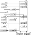
- the control unit 70 controls a series of operation operations including washing, rinsing, dehydration, and drying based on setting information input from the user via the input setting unit 32 and operation state monitoring of each unit. For example, in the drying process, the control unit 70 controls the rotation of the drum drive motor 3 via the motor drive circuit 22, controls the operations of the blower unit 4 and the heat pump device 50, and further controls the air path switching unit 12.
- the first air path 9 and the second air path 11 are switched by control.
- the control unit 70 includes, for example, a CPU (Central Processing Unit) (not shown), a ROM (Read Only Memory) that stores programs, a RAM (Random Access Memory) that stores programs and data when various processes are executed, an input / output interface, and the like. Can be configured by a bus connecting the two.
- the control unit 70 has a timer 71 that measures the time from the start of the drying process.
- the timer 71 an internal timer incorporated as an internal function in the operation of the control unit 70 can be used.
- a timer device independent from the control unit 70 can be used.
- control unit 70 includes an air path control unit 72, an air volume control unit 73, a compressor control unit 74, and a pressure reduction control unit 75.
- the air path control unit 72 selectively switches the air path to the first air path 9 or the second air path 11 by controlling the air path switching unit 12 during the drying process.
- the air volume control unit 73 controls the air blowing unit 4 to adjust the air volume of the drying air in the circulation air path 13.
- the compressor control unit 74 controls the rotational speed of the compressor 16.
- the pressure reduction control unit 75 adjusts the pressure reduction amount of the pressure reducer 18 (throttle amount of the expansion valve).
- the air path control part 72, the air volume control part 73, the compressor control part 74, and the pressure reduction control part 75 are realizable when CPU performs the operation
- the air volume control unit 73 blows drying air having a low speed and a large air flow from the first air outlet 8 into the drum 1 than when the second air passage 11 is selected.
- the second air path 11 air is blown so that drying air at a higher speed is blown out from the second air outlet 10 into the drum 1 than when the first air path 9 is selected. Control part 4.
- the compressor control unit 74 changes the rotational speed of the compressor 16 in accordance with the change in the air volume of the drying air in the circulation air passage 13. Specifically, the compressor control unit 74 reduces the rotational speed of the compressor 16 when the air volume of the drying air in the circulation air path 13 decreases, while the air volume of the drying air in the circulation air path 13. Is increased, the rotational speed of the compressor 16 is increased.
- the depressurization control unit 75 changes the depressurization amount of the depressurizer 18 in accordance with fluctuations in the rotation speed of the compressor 16. Specifically, the decompression control unit 75 increases the amount of decompression of the decompressor 18 as the rotation speed of the compressor 16 decreases, while the decompression controller 75 increases the rotation speed of the compressor 16. Decrease 18 vacuum.
- the refrigerant compressed to a high temperature and high pressure by the compressor 16 enters the radiator 17 and heat-exchanges with the surrounding air (drying air passing through the circulation air passage 13) to heat the air, and the refrigerant is cooled.
- the liquefied high-pressure refrigerant is decompressed by the decompressor 18 to become a low-temperature and low-pressure liquid refrigerant, and then enters the heat absorber 19 to exchange heat with the surrounding air (drying air passing through the circulation air passage 13). Then, the air is dehumidified and cooled, and the refrigerant is heated to become vapor refrigerant and returns to the compressor 16.
- the drying air sent out by the blower 4 enters the drum 1 through the water tank 2 and dries the clothes in the drum 1 to enter the heat pump device 50 as humid air.
- the heat pump device 50 first, the drying air is dehumidified and cooled in the heat absorber 19. Next, the drying air flows into the radiator 17 and is heated to become high-temperature and low-humidity air, and returns to the blower unit 4.
- the compressor controller 74 reduces the rotational speed of the compressor 16 when the temperature detected by the temperature sensor 16a attached to the discharge pipe of the compressor 16 exceeds a specified value. The deterioration of the lubricating oil in the compressor 16 is suppressed.
- the compressor control unit 74 increases the rotational speed of the compressor 16, If the detected temperature of the temperature sensor 17a is higher than a specified value, the compressor control unit 74 performs control such as reducing the rotational speed of the compressor 16.
- the compressor control unit 74 increases the rotational speed of the compressor 16, while the temperature If the detected temperature of the sensor 17a is higher than the specified value, the compressor control unit 74 performs control such as reducing the rotational speed of the compressor 16.
- control of the rotation speed of the compressor 16 by the compressor control unit 74 is not control based on fluctuations in the air volume of the drying air passing through the circulation air path 13, but even when the air volume of the drying air is constant. Normal control to be executed.
- the compressor control unit 74 also performs control to change the rotation speed of the compressor 16 according to the air volume fluctuation of the drying air in the circulation air passage 13. Yes.
- this control will be described with reference to FIGS. 4 and 5.
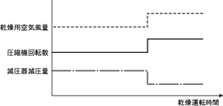
- FIG. 4 shows the rotational speed control of the compressor 16 by the compressor control unit 74 when the air volume of the drying air in the circulation air passage 13 is rapidly reduced.
- the decompression amount control of the decompressor 18 by the decompression control unit 75 is also shown.
- the air volume of the drying air in the circulation air passage 13 decreases during the drying process, for example, there are the following cases. That is, since a large amount of moisture is contained in the clothing at the initial stage of the drying process, drying can be promoted by applying a large amount of air to the clothing using the first air passage 9. Since the amount of power consumption of the air blowing unit 4 increases when the air is continuously generated, when the drying proceeds to some extent, the air amount of the drying air is reduced to perform the energy saving operation. In this case, the air volume of the drying air in the circulation air passage 13 is rapidly reduced at the timing of switching to the energy saving operation.
- the air volume of the drying air decreases during the drying process
- the first air passage 9 is used to apply a large amount of drying air to the clothing to promote drying, and when the wrinkles are likely to be formed in the clothing in the late drying stage, By switching to the path 11, the crease of the clothes is reduced by applying high-pressure and high-speed drying air to the clothes with a small air volume. In this case, at the timing when the first air passage 9 is switched to the second air passage 11, the air volume of the drying air in the circulation air passage 13 is rapidly reduced.
- the compressor control unit 74 of the present embodiment is linked to the decrease in the air volume of the drying air in the circulation air path 13, and the compressor 16 according to the decrease amount. Control is performed to reduce the rotational speed. Thus, if the rotation speed of the compressor 16 is reduced, the circulation amount of the refrigerant in the heat pump device 50 can be reduced.
- the circulation amount of the refrigerant also decreases (that is, the drying air due to the decrease in the air volume).
- the refrigerant circulation amount is reduced to reduce the refrigerant heat exchange amount).
- the decompression control unit 75 of the present embodiment performs control to increase the decompression amount of the decompressor 18 (throttle amount of the expansion valve) as the rotational speed of the compressor 16 decreases. I do. If the rotation speed of the compressor 16 decreases, the pressure of the high-pressure side (heat radiator 17 side) refrigerant in the heat pump device 50 decreases, and the pressure of the low-pressure side (heat absorber 19 side) refrigerant increases. In this case, since the temperature of the low-pressure side refrigerant rises, the dehumidifying ability in the heat absorber 19 is somewhat lowered.
- the pressure increase of the refrigerant in the heat absorber 19 can be suppressed by increasing the pressure reduction amount of the pressure reducer 18.
- the dehumidification performance in the heat absorber 19 can be maintained.
- the pressure reduction amount of the pressure reducer 18 is increased, a decrease in the pressure of the high pressure side (heat radiator 17 side) refrigerant can be suppressed. Thereby, the heating performance in the heat radiator 17 can also be maintained.
- the amount of refrigerant circulating in the heat pump device 50 can be further reduced by increasing the amount of decompression of the decompressor 18 (throttle amount of the expansion valve). Therefore, the control range in which the circulation amount of the refrigerant can be reduced is expanded by combining the reduction control of the rotational speed of the compressor 16 by the compressor control unit 74 and the increase control of the decompression amount of the decompressor 18 by the decompression control unit 75. can do. Thereby, it becomes possible to easily cope with a large change in the air volume of the drying air.
- FIG. 5 shows the rotational speed control of the compressor 16 by the compressor control unit 74 when the air volume of the drying air in the circulation air passage 13 is rapidly increased.
- the decompression amount control of the decompressor 18 by the decompression control unit 75 is also shown.
- the air volume of the drying air in the circulation air passage 13 increases during the drying process, for example, there are the following cases. That is, when it is assumed that there is only one air passage as shown in FIG. 1 and there is only one air passage, wrinkle reduction of the clothing can be reduced by applying high-speed drying air to the clothing as described above. In order to achieve this, it is necessary to increase the number of revolutions of the blower 4 to generate high-speed and large-volume air for drying. In this case, the amount of power consumption increases when high-speed and large-volume drying air is generated from the beginning of the drying process.
- the rotational speed of the blower 4 is increased, and high-speed and large air-drying air is applied to the clothes to reduce the wrinkles of the clothes.
- the air volume of the drying air in the circulation air passage 13 increases abruptly at the timing when the rotational speed of the blower 4 is increased.
- the air path is switched from the second air path 11 to the first air path 9 in the configuration having two air paths as shown in FIG.
- the second air passage 11 is used to reduce the wrinkles of the clothes by applying high-speed and small air-drying air to the clothes, and then the drying progresses so that the wrinkles are not easily generated.
- the air flow is switched to the first air passage 9, and the drying air of low speed and large air volume is applied to the clothing to shorten the drying time and reduce the power consumption.
- the air volume of the drying air in the circulation air passage 13 increases abruptly at the timing when the second air passage 11 switches to the first air passage 9.
- the compressor control unit 74 of the present embodiment is interlocked with the increase in the air volume of the drying air in the circulation air path 13, and the compressor 16 according to the increase amount. Control to increase the number of revolutions.
- the circulation amount of the refrigerant in the heat pump device 50 can be increased. That is, as the air volume of the drying air is increased and the amount of heat exchange with the drying air in the heat absorber 19 is increased, the circulation amount of the refrigerant is also increased (that is, the drying air is increased by the increase in the air volume). As the amount of heat exchange increases, the amount of refrigerant circulating is increased to increase the amount of refrigerant heat exchanged). Thereby, even if the air volume of drying air increases, the increase in the degree of refrigerant superheating at the outlet of the heat absorber 19 can be suppressed. Therefore, it is possible to maintain the temperature of the refrigerant discharged from the compressor 16 within a specified value, avoiding the inconvenience that the compressor 16 stops, and improving the reliability of the heat pump device 50.
- the decompression control unit 75 of the present embodiment controls to reduce the decompression amount (throttle amount of the expansion valve) of the decompressor 18 as the rotational speed of the compressor 16 increases. I do. Thereby, the pressure of the refrigerant
- the control range in which the circulation amount of the refrigerant can be increased is expanded. can do. Thereby, it becomes possible to easily cope with a large change in the air volume of the drying air.
- the wind speed / circulation in the circulation air path 13 such as a venturi tube or a biram anemometer
- a detection device capable of directly measuring the air volume can be used.
- the input detection unit 80 that detects the air blowing unit input that determines the air blowing capacity of the air blowing unit 4 is used (see FIG. 3). ). That is, the compressor control unit 74 of the control unit 70 determines the variation in the air volume of the drying air flowing in the circulation air path 13 based on the blower unit input detected by the input detection unit 80.
- a control signal (a signal for determining the number of rotations of the blower fan motor 4b of the blower 4) input from the air volume controller 73 to the blower 4 can be used.
- the air path is fixed to the first air path 9
- the air volume of the drying air passing through the first air path 9 increases as the blower input detected by the input detection unit 80 increases. Therefore, the increase / decrease in the air volume can be easily determined based on the air blower input.
- the air volume does not always increase just because the air blower input becomes large. That is, when the second air passage 11 having the second air outlet 10 having an air passage cross-sectional area smaller than that of the first air outlet 8 is selectively used, the blower unit input is performed more than when the first air passage 9 is selected. Even if the air pressure is large, the airflow is small but high. Even in such a case, since the air passage cross-sectional area of each air passage is known, if the air passage cross-sectional area of the currently selected air passage is also taken into consideration, the air blowing portion detected by the input detection portion 80 Based on the input, the air volume of the drying air can be calculated.
- the heat radiator 17 is affected by the heat absorber 19, so that the response by the control based on the temperature detection is delayed as described above. It is necessary to detect the change in the air volume and control the rotational speed of the compressor 16 accordingly.
- the control according to the present embodiment makes it possible to quickly adjust the refrigerant circulation amount in accordance with the fluctuation of the heat exchange amount between the heat absorber and the drying air due to the fluctuation of the air volume of the drying air, and the failure of the compressor In addition, a reliable selective dryer or clothes dryer can be realized.
- the air path switching unit is inexpensively configured by temporarily reducing the air blowing capacity of the air blowing unit 4 (including stopping the air blowing) immediately before operating the air path switching unit 12. 12 is operated smoothly.
- the drying air is circulated through the circulation air passage 13. If it does not flow for a short time, the high-pressure side pressure of the heat pump device 50 will rise rapidly, causing an excessive temperature rise in the heating unit 7 (heat radiator 17), possibly causing the compressor 16 to malfunction. Therefore, in the present embodiment, in order to reliably avoid a failure due to an excessive temperature rise in the heating unit 7, the rotational speed control timing of the compressor 16, the control timing of the blower unit 4, and the control timing of the air path switching unit 12 are as follows. It is deliberately shifted as explained in
- FIG. 6 is a time chart showing an example of the air path switching operation.
- the control unit 70 controls the air path switching unit 12 to open the first air path 9 side, and starts the drying operation. Further, the control unit 70 starts the time measurement by the timer 71 simultaneously with the start of the drying operation, and continues the low wind speed large air volume mode from time t0 to dt1.
- t0 which is a predetermined time
- dt1, dt2, dt3, and dt4 are constants of about several tens of seconds, respectively.
- the compressor 16 is rotated by the compressor control unit 74 so that the temperature detected by the temperature sensor 17a for detecting the condensation temperature of the refrigerant in the radiator 17 becomes the set temperature. Be controlled.
- the switching mode is from time t0-dt1 to t0 + dt3.
- the compressor control unit 74 temporarily reduces the rotational speed of the compressor 16.
- the rotation speed of the compressor 16 is set to the minimum rotation speed, and the condensation temperature of the refrigerant in the radiator 17 is greatly reduced.
- the air volume control unit 73 temporarily reduces the blowing capacity of the blowing unit 4.
- the number of rotations of the blower fan motor 4b is set to zero, and the blowing is temporarily stopped.
- the compressor 16 since the compressor 16 is operating at the minimum rotational speed, an increase in the refrigerant condensing temperature in the radiator 17 is suppressed to a minimum.
- the air path control unit 72 operates the air path switching unit 12 to switch the second air path 11 to be open.
- time t0 which is a predetermined time
- the air path control unit 72 operates the air path switching unit 12 to switch the second air path 11 to be open.
- the air path switching unit 12 since the air blowing of the air blowing unit 4 is stopped, no wind force acts on the air path switching unit 12, and the valve 12a can be smoothly driven with a small rotational torque.
- the air path switching unit 12 is driven in a state where the air blowing is stopped, the operation can be performed smoothly, so that the air path switching sound can be suppressed low, which is effective for noise prevention. .
- the air volume control unit 73 rotates the blower fan motor 4b at a large number of revolutions so as to increase the blower capacity of the blower unit 4 that has been temporarily reduced (stopped) to a set value.
- the compressor control unit 74 returns the rotational speed of the compressor 16 that has been temporarily reduced to the set value so that the condensation temperature of the refrigerant in the radiator 17 becomes the set temperature. Thereby, the excessive temperature rise of the heating part 7 (heat radiator 17) immediately after air path switching can be suppressed.
- the compressor control unit 74 temporarily reduces the rotation speed of the compressor 16 (for example, to the minimum rotation speed).
- the air volume control unit 73 temporarily reduces the blowing capacity of the blowing unit 4 (for example, the rotational speed of the blower fan motor 4b is set to zero). Then, the air path control unit 72 operates the air path switching unit 12 to switch the air path. Thereby, failure of the heat pump device 50 due to excessive temperature rise of the heating unit 7 at the time of air path switching can be prevented in advance.
- valve 12a can be operated in a state where the wind force acting on the valve 12a of the air path switching unit 12 is suppressed, it is not necessary to use a motor that generates a large rotational torque in the air path switching unit 12, Cost reduction can be achieved.
- the rotational speed of the blower fan motor 4b that has been temporarily reduced (stopped) by the air volume control unit 73 is set to the set value.
- the rotation speed of the compressor 16 temporarily reduced by the compressor control unit 74 is returned to the set value.
- the compressor 16 driven by the compressor control unit 74, the radiator 17 (heating unit 7), the decompressor 18, and the heat absorber 19 (dehumidifying unit 6) constitute the heat pump device 50, and the compression unit
- the heating capacity of the radiator 17 (heating unit 7) is varied by varying the number of rotations of 16.
- the compressor control part 74 which drives the compressor 16 is provided, the said compressor control part 74 reduces a capability to the minimum, without stopping the compressor 16, and the air volume control part 73 is the air blower part 4 after that.
- the ventilation capacity is temporarily reduced, and then the air path control unit 72 operates the air path switching unit 12 to switch the air path. Accordingly, it is possible to prevent the drying time from being extended unnecessarily without stopping the compression unit 16, and it is possible to reliably suppress overheating of the heating unit 7 (heat radiator 17) and the compressor 16.
- the first air passage 9 is configured such that the air passage cross-sectional area of the first air outlet 8 is increased so that low-speed and large-volume air can be blown out from the rear of the drum 1, and the second air passage 11.
- the air passage cross-sectional area of the second air outlet 10 can be reduced so that a high-speed and small air volume can be blown out from the front of the drum 1.
- the drum type washing and drying machine of the present embodiment can achieve a good dry finish with less generation of wrinkles of clothes while saving power.
- the discharge port 5 is disposed at a position close to the second air outlet 10 in front of the drum 1 and far from the first air outlet 8.
- the distance between the first air outlet 8 and the exhaust port 5 becomes long, and air is being blown from the first air outlet 8 behind the drum 1.
- the drying air blown out from the first air outlet 8 spreads widely in the drum 1. Accordingly, the clothes and the drying air are efficiently in contact with each other in the drum 1, and the clothes can be dried with a small amount of power consumption.
- the second air outlet 10 is used for drying at high pressure and high wind speed. Since the air is blown out, the drying air can reach from the front of the drum 1 to the rear. Thereby, the contact between the drying air and the clothes does not deteriorate, and the effect of stretching the wrinkles with the high-pressure and high-winding drying air can be maintained.
- the first air passage 9 having a large air passage cross-sectional area and a small pressure loss is used, and a large amount of air for drying is used. It blows out from the 1st blower outlet 8 of drum 1 back, and hits clothing.
- the pressure loss of the first air passage 9 is small, even if the rotational speed of the blower fan motor 4b is relatively low and the blower unit 4 is driven with low power consumption, a large amount of wind can be obtained. it can. Therefore, it is possible to shorten the drying time in the first half of drying and reduce the power consumption during this period.
- the air path switching unit 12 switches to the second air path 11 to increase the rotational speed of the blower fan motor 4b.
- high-pressure and high-speed drying air obtained by rotating the blower fan motor 4b at a large rotational speed is blown from the second blower outlet 10 having an air passage cross-sectional area smaller than that of the first blower outlet 8. Is done. In this case, wrinkles are reduced because the clothes are always spread by the high-pressure and high-speed wind.
- the cloth amount detection unit 15 is provided and the control unit 70 sets a predetermined time for separating the first half of drying and the second half of drying according to the amount of clothes.
- the control unit 70 sets a predetermined time for separating the first half of drying and the second half of drying according to the amount of clothes.
- the operation of the cloth amount detection unit 15 is to detect the amount (mass) of clothes put on the drum 1 as follows before the start of washing. That is, the cloth amount detection unit 15 is configured so that the position of the shaft of the damper 14 in a state where the water tank 2 is empty (no water is present in the water tank 2 and no clothes are put in the drum 1) and before the start of washing. Then, the water is put into the drum 1 due to the difference between the position of the shaft of the damper 14 in the state before the water is poured into the water tank 2 (the water is not present in the water tank 2 but the clothing is present in the drum 1). Detect the amount of clothing applied.
- the cloth amount detection unit 15 is exemplified by a method of detecting the amount of vertical displacement of the shaft of the damper 14, but is not limited to this.
- the amount of cloth is detected by detecting the amount of change in the rotational speed, drive current, torque, etc. of the drum drive motor 3 that rotates the drum 1 and detecting the amount of clothing in the drum 1 from the load change of the drum drive motor 3. Part may be applied.
- control unit 70 automatically changes the predetermined time for separating the first half of drying and the second half of drying according to the detection result of the cloth amount detection unit 15 is shown. Even when the user does not exist, the user can input the amount of clothes from the input setting unit 32, and the control unit 70 can change the predetermined time according to the input of the user.
- a clothes dryer includes a storage unit that stores clothes to be dried, a compressor that compresses refrigerant, a radiator, and a high-pressure refrigerant radiated by the radiator.
- a heat pump device in which a decompressor and a heat absorber are sequentially connected by a pipe line so that the refrigerant circulates, and a blower unit that blows drying air is arranged in the middle of the air passage, and the housing unit, the heat absorber, and the A circulation air passage that circulates the drying air sequentially to the accommodating portion through a radiator, an air flow control portion that controls the air blowing portion and adjusts the air amount of the drying air in the circulation air passage, and A compressor control unit that controls the rotation speed of the compressor, and the compressor control unit changes the rotation speed of the compressor in accordance with a change in the air volume of the drying air in the circulation air passage. It is.
- the housing part, the heat absorber and the radiator are arranged in the circulation air passage, and the drying air that has passed through the heat absorber is immediately after the radiator. Pass through.
- the heat absorber and radiator are installed in the same circulation air passage, so that The condition of the heat exchange based on it is not divided and is exposed to the same environment.
- the heat exchange amount between the heat absorber arranged in the circulation air passage and the drying air also changes abruptly and is normally used.
- the compressor control unit performs control to change the rotational speed of the compressor in accordance with the change in the air volume of the drying air in the circulation air passage.
- the compressor control unit reduce the rotational speed of the compressor when the air volume of the drying air in the circulation air passage is reduced.
- the compressor control unit of the present invention performs control to reduce the rotational speed of the compressor in conjunction with the decrease in the air volume of the drying air in the circulation air path.
- the compressor control unit increase the rotational speed of the compressor when the air volume of the drying air in the circulation air passage is increased.
- the compressor control unit of the present invention performs control to increase the rotational speed of the compressor in conjunction with the increase in the amount of drying air in the circulation air passage.
- coolant in a heat pump apparatus can be enlarged.
- the circulation amount of the refrigerant also increases. Therefore, even if the air volume of drying air increases, the increase in the degree of refrigerant superheating on the outlet side of the heat absorber can be suppressed. Therefore, it is possible to maintain the temperature of the refrigerant discharged from the compressor within a specified value, avoiding the inconvenience that the compressor stops, and improving reliability.
- a plurality of air passages that constitute a part of the circulation air passage and have a blow-out port that blows drying air into the accommodating portion, and an air passage switching portion that selectively switches the plurality of air passages.
- An air path control unit that controls the air path switching unit during the drying process to change the air path, and before the air path control unit changes the air path during the drying process, the compressor After the control unit temporarily reduces the rotation speed of the compressor, the air volume control unit temporarily reduces the air blowing capacity of the air blowing unit, and then the air path control unit turns the air path switching unit. It is preferable to change the air path by operating.
- the compressor control unit temporarily reduces the rotational speed of the compressor. Failure of the heat pump device due to overheating of the vessel can be reliably prevented. After that, since the blowing capacity of the blowing section is temporarily reduced, the wind path switching section can be operated in a state where the wind force acting on the wind path switching section is suppressed, which is great for driving the wind path switching section. No power source is required, and power saving and cost reduction can be achieved. Further, since the air path can be switched smoothly with a slight force, the air path switching unit can be operated quietly, and noise can be reduced.
- An air path switching unit that selectively switches the second air path; and an air path control unit that controls the air path switching unit to change the air path during the drying process, and the air volume control unit includes: When the first air path is selected, drying air having a low speed and a large air volume is blown out from the first air outlet into the housing portion, compared with when the second air path is selected.
- the air blowing unit When the air path is selected, the air blowing unit is controlled so that drying air at a higher speed than that when the first air path is selected is blown out from the second air outlet into the housing unit, and during the drying process Before the air path control unit changes the air path, the compressor control unit operates the compressor. After the number is temporarily reduced, the air volume control unit temporarily reduces the air blowing capacity of the air blowing unit, and then the air path control unit operates the air path switching unit to change the air path. It is preferable.
- the two air paths, the 1st air path and the 2nd air path are provided as an air path which introduces the air for drying into the storage part which stores clothes, and the two air paths are It can be switched by the air path switching unit.
- the first air outlet of the first air passage has a larger air passage cross-sectional area and less pressure loss than the second air outlet of the second air passage.
- the second air outlet of the second air passage has an air passage cross-sectional area smaller than that of the first air outlet. And when the 2nd air path is selected, the high-pressure high-speed drying air is blown out from the 2nd blower outlet in the accommodating part rather than the time when the 1st air path is selected. In this case, since the clothes are spread by the high-pressure and high-speed wind, the generation of wrinkles can be reduced.
- the air blowing capacity of the air blowing unit that has been temporarily reduced by the air volume control unit is a set value. It is preferable to increase the number of rotations of the compressor, which has been temporarily reduced by the compressor control unit, to a set value.
- the compressor control unit temporarily reduces the rotation speed of the compressor, it is preferable to reduce the compression capability to the minimum without stopping the compressor. Thereby, it is possible to prevent the drying time from being unnecessarily extended without stopping the compression unit, and it is possible to reliably suppress the excessive temperature rise of the radiator and the compressor.
- a pressure reduction control unit that controls the pressure reducer is further provided, and the pressure reduction control unit may increase the pressure reduction amount of the pressure reducer as the number of rotations of the compressor decreases. preferable.
- the pressure reduction amount of a decompressor is increased, the fall of the pressure of a high voltage
- coolant can also be suppressed. Thereby, the heating performance in a radiator can also be maintained.
- the circulation amount of the refrigerant in the heat pump device can be further reduced by increasing the decompression amount of the decompressor. Therefore, the control range in which the circulation amount of the refrigerant can be reduced can be expanded by combining the reduction control of the compressor speed by the compressor control unit with the increase control of the decompression amount of the decompressor by the decompression control unit. . Thereby, it becomes possible to easily cope with a large change in the air volume of the drying air.
- the decompression control unit described above decreases the decompression amount of the decompressor as the rotational speed of the compressor increases.
- coolant in a radiator can be reduced, and it can prevent that the pressure of a refrigerant
- the circulation amount of the refrigerant in the heat pump device can be further increased by reducing the amount of decompression of the decompressor. Therefore, the control range in which the circulation amount of the refrigerant can be increased can be expanded by combining the increase control of the rotation speed of the compressor by the compressor control unit and the decrease control of the decompression amount of the decompressor by the decompression control unit. . Thereby, it becomes possible to easily cope with a large change in the air volume of the drying air.
- the decompressor is preferably an electric expansion valve.
- the pressure reduction amount can be easily changed by adjusting the throttle amount of the expansion valve.
- an input detection unit that detects a blower input that determines a blower capacity of the blower is further provided, and the compressor control unit is based on an increase / decrease in a blower input detected by the input detection unit.
- the compressor control unit is based on an increase / decrease in a blower input detected by the input detection unit.
- a washing / drying machine includes any of the above-described clothes drying machines and a water tank that encloses the housing portion and stores washing water.
- a highly reliable washing dryer can be realized.
- the drum-type washing and drying machine has a control unit 170. Similar to the drum-type washing and drying machine according to the first embodiment, the control unit 170 performs washing and rinsing based on setting information input from the user via the input setting unit 32 and operation state monitoring of each unit. Controls a series of driving operations from dehydration and drying. For example, in the drying process, the control unit 170 controls the rotation of the drum drive motor 3 via the motor drive circuit 22, controls the operation of the blower unit 4 and the heat pump device 50, and further controls the air path switching unit 12. The first air path 9 and the second air path 11 are switched by control.
- the controller 170 includes, for example, a CPU (Central Processing Unit) (not shown), a ROM (Read Only Memory) that stores programs, a RAM (Random Access Memory) that stores programs and data when various processes are executed, an input / output interface, and the like. Can be configured by a bus connecting the two.
- the control unit 170 has a timer 71 that measures the time from the start of the drying process. As this timer 71, an internal timer incorporated as an internal function in the operation of the control unit 170 can be used. As the timer 71, a timer device independent from the control unit 170 can be used.
- control unit 170 includes an air path control unit 72, an air volume control unit 73, a compressor control unit 174, and a pressure reduction control unit 175.
- the air path control unit 72 selectively switches the air path to the first air path 9 or the second air path 11 by controlling the air path switching unit 12 during the drying process.
- the air volume control unit 73 controls the air blowing unit 4 to adjust the air volume of the drying air in the circulation air path 13.
- the compressor control unit 174 controls the operation / stop of the compressor 16 that operates at a constant speed (rotation speed).
- the pressure reduction control unit 175 adjusts the pressure reduction amount of the pressure reducer 18 (throttle amount of the expansion valve).
- the air path control part 72, the air volume control part 73, the compressor control part 174, and the pressure reduction control part 175 are implement
- the air volume control unit 73 blows drying air having a low speed and a large air flow from the first air outlet 8 into the drum 1 than when the second air passage 11 is selected.
- the second air path 11 air is blown so that drying air at a higher speed is blown out from the second air outlet 10 into the drum 1 than when the first air path 9 is selected. Control part 4.
- the decompression control unit 175 changes the throttle amount of the decompressor 18 in accordance with the air volume fluctuation of the drying air in the circulation air path 13. Specifically, the decompression control unit 175 increases the throttle amount of the decompressor 18 when the air volume of the drying air in the circulation air path 13 decreases, while the air volume of the drying air in the circulation air path 13 increases. When it increases, the throttle amount of the decompressor 18 is decreased.
- the compressor control unit 174 stops the compressor 16 and suppresses deterioration of the lubricating oil in the compressor 16.
- the compressor 16 is started again.
- the compressor control unit 174 obtains the degree of superheat from the detected temperature difference between the temperature sensor attached to the outlet pipe of the heat absorber 19 and the temperature sensor attached to the pipe in the heat absorber 19, and the degree of superheat is When it becomes below the specified value, the operation of the compressor 16 is stopped to prevent liquid compression, and when the degree of superheat exceeds the specified value, the compressor 16 is started again.
- the decompression control unit 175 also performs control to change the throttle amount of the decompressor 18 in accordance with the air volume variation of the drying air in the circulation air passage 13. .
- this control will be described with reference to FIGS.
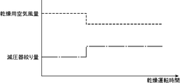
- FIG. 8 shows the throttle amount control of the decompressor 18 by the decompression control unit 175 when the air volume of the drying air in the circulation air path 13 is rapidly reduced.
- the air volume of the drying air in the circulation air passage 13 decreases during the drying process, for example, there are the following cases. That is, since a large amount of moisture is contained in the clothing at the initial stage of the drying process, drying can be promoted by applying a large amount of air to the clothing using the first air passage 9. Since the amount of power consumption of the air blowing unit 4 increases when the air is continuously generated, when the drying proceeds to some extent, the air amount of the drying air is reduced to perform the energy saving operation. In this case, the air volume of the drying air in the circulation air passage 13 is rapidly reduced at the timing of switching to the energy saving operation.
- the air volume of the drying air decreases during the drying process
- the first air passage 9 is used to apply a large amount of drying air to the clothing to promote drying, and when the wrinkles are likely to be formed in the clothing in the late drying stage, By switching to the path 11, the crease of the clothes is reduced by applying high-pressure and high-speed drying air to the clothes with a small air volume. In this case, at the timing when the first air passage 9 is switched to the second air passage 11, the air volume of the drying air in the circulation air passage 13 is rapidly reduced.
- the decompression control unit 175 of the present embodiment is linked to the reduction in the air volume of the drying air in the circulation air path 13, and the throttle of the decompressor 18 is reduced according to the reduction quantity. Control to increase the amount.
- the amount of refrigerant circulating in the heat pump device 50 can be reduced. That is, according to the state where the air volume of the drying air is reduced and the heat exchange amount with the drying air in the heat absorber 19 is reduced, the circulation amount of the refrigerant is also reduced (that is, the drying air due to the air volume reduction is reduced). In accordance with the decrease in the heat exchange amount, the refrigerant circulation amount is reduced to reduce the refrigerant heat exchange amount). Thereby, even if the air volume of the drying air decreases, the refrigerant can be completely vaporized at the outlet of the heat absorber 19.
- the liquid refrigerant is compressed by the compressor 16 and breaks down, and the reliability of the washing dryer (or clothes dryer) using the heat pump device 50 is improved. Since the dehumidification can be performed continuously without stopping the compressor 16 due to the improvement in reliability, the drying operation time can be shortened. Further, by increasing the throttle amount of the pressure reducer 18, the effect of reducing the refrigerant circulation amount as well as the effect of reducing the pressure of the refrigerant in the heat absorber 19 can be achieved. Can be maintained.
- FIG. 9 shows the throttle amount control of the decompressor 18 by the decompression controller 175 when the air volume of the drying air in the circulation air passage 13 increases rapidly.
- the air volume of the drying air in the circulation air passage 13 increases during the drying process, for example, there are the following cases. That is, when it is assumed that there is only one air passage as shown in FIG. 1 and there is only one air passage, wrinkle reduction of the clothing can be reduced by applying high-speed drying air to the clothing as described above. In order to achieve this, it is necessary to increase the number of revolutions of the blower 4 to generate high-speed and large-volume air for drying. In this case, the amount of power consumption increases when high-speed and large-volume drying air is generated from the beginning of the drying process.
- the rotational speed of the blower 4 is increased, and high-speed and large air-drying air is applied to the clothes to reduce the wrinkles of the clothes.
- the air volume of the drying air in the circulation air passage 13 increases abruptly at the timing when the rotational speed of the blower 4 is increased.
- the air path is switched from the second air path 11 to the first air path 9 in the configuration having two air paths as shown in FIG.
- the second air passage 11 is used to reduce the wrinkles of the clothes by applying high-speed and small air-drying air to the clothes, and then the drying progresses so that the wrinkles are not easily generated.
- the air flow is switched to the first air passage 9, and the drying air of low speed and large air volume is applied to the clothing to shorten the drying time and reduce the power consumption.
- the air volume of the drying air in the circulation air passage 13 increases abruptly at the timing when the second air passage 11 switches to the first air passage 9.
- the decompression control unit 175 is linked to the increase in the air volume of the drying air in the circulation air path 13, and the throttle of the decompressor 18 according to the increase amount. Control to reduce the amount.
- the amount of refrigerant circulating in the heat pump device 50 can be increased. That is, as the air volume of the drying air is increased and the amount of heat exchange with the drying air in the heat absorber 19 is increased, the circulation amount of the refrigerant is also increased (that is, the drying air is increased by the increase of the air volume). As the amount of heat exchange increases, the amount of refrigerant circulation increases to increase the amount of heat exchange of the refrigerant. Thereby, even if the air volume of drying air increases, the increase in the degree of refrigerant superheating at the outlet of the heat absorber 19 can be suppressed.
- the wind speed / circulation in the circulation air path 13 such as a venturi tube or a biram anemometer
- a detection device capable of directly measuring the air volume can be used.
- the input detection unit 80 that detects the air blowing unit input that determines the air blowing capacity of the air blowing unit 4 is used (see FIG. 7). ). That is, the decompression control unit 175 of the control unit 170 determines the variation in the air volume of the drying air flowing in the circulation air path 13 based on the air blowing unit input detected by the input detection unit 80.
- a control signal (a signal for determining the number of rotations of the blower fan motor 4b of the blower 4) input from the air volume controller 73 to the blower 4 can be used.
- the air path is fixed to the first air path 9
- the air volume of the drying air passing through the first air path 9 increases as the blower input detected by the input detection unit 80 increases. Therefore, the increase / decrease in the air volume can be easily determined based on the air blower input.
- the air volume does not always increase just because the air blower input becomes large. That is, when the second air passage 11 having the second air outlet 10 having an air passage cross-sectional area smaller than that of the first air outlet 8 is selectively used, the blower unit input is performed more than when the first air passage 9 is selected. Even if the air pressure is large, the airflow is small but high. Even in such a case, since the air passage cross-sectional area of each air passage is known, if the air passage cross-sectional area of the currently selected air passage is also taken into consideration, the air blowing portion detected by the input detection portion 80 Based on the input, the air volume of the drying air can be calculated.
- the heat radiator 17 is affected by the heat absorber 19, so that the response by the control based on the temperature detection is delayed as described above. It is necessary to detect a change in the air volume and control the amount of restriction of the decompressor accordingly.
- the control according to the present embodiment makes it possible to quickly adjust the refrigerant circulation amount in accordance with the fluctuation of the heat exchange amount between the heat absorber and the drying air due to the fluctuation of the air volume of the drying air, and the failure of the compressor In addition, a reliable selective dryer or clothes dryer can be realized.
- the air path switching unit is inexpensively configured by temporarily reducing the air blowing capacity of the air blowing unit 4 (including stopping the air blowing) immediately before operating the air path switching unit 12. 12 is operated smoothly.
- the drying air is circulated through the circulation air path. If it does not flow through 13 even for a short time, the high-pressure side pressure of the heat pump device 50 will rise rapidly, causing an excessive temperature rise in the heating unit 7 (heat radiator 17), possibly causing the compressor 16 to malfunction. Therefore, in the present embodiment, in order to reliably avoid a failure due to excessive temperature rise of the heating unit 7, the throttle amount control timing of the decompressor 18, the control timing of the blower unit 4, and the control timing of the air path switching unit 12 are as follows. It is intentionally shifted as explained in
- FIG. 10 is a time chart showing an example of the air path switching operation.
- the control unit 170 controls the air path switching unit 12 to open the first air path 9 side, and starts the drying operation.
- the control unit 170 starts the time measurement by the timer 71 simultaneously with the start of the drying operation, and continues the low wind speed large air volume mode from time t0 to dt1.
- t0 which is a predetermined time
- dt1, dt2, dt3, and dt4 are constants of about several tens of seconds.
- the switching mode is from time t0-dt1 to t0 + dt3.
- the decompression control unit 175 temporarily increases the throttle amount of the decompressor 18.
- the throttle amount of the decompressor 18 is set to the maximum to reduce the circulation amount of the refrigerant, and the condensation temperature of the refrigerant in the radiator 17 is greatly reduced.
- the air volume control unit 73 temporarily reduces the blowing capacity of the blowing unit 4. In this example, the number of rotations of the blower fan motor 4b is set to zero, and the blowing is temporarily stopped.
- the air path control unit 72 operates the air path switching unit 12 to switch the second air path 11 to be open. At this time, since the air blowing of the air blowing unit 4 is stopped, no wind force acts on the air path switching unit 12, and the valve 12a can be smoothly driven with a small rotational torque.
- the air volume control unit 73 rotates the blower fan motor 4b at a large number of revolutions so as to increase the blower capacity of the blower unit 4 that has been temporarily reduced (stopped) to a set value.
- the decompression control unit 175 returns the throttle amount of the decompressor 18 that has been temporarily increased to the set value so that the condensation temperature of the refrigerant in the radiator 17 becomes the set temperature. Thereby, the excessive temperature rise of the heating part 7 (heat radiator 17) immediately after air path switching can be suppressed.
- the decompression control unit 175 temporarily increases the throttle amount of the decompressor 18 (for example, maximizes the throttle amount).
- the air volume control unit 73 temporarily reduces the blowing capacity of the blowing unit 4 (for example, the rotational speed of the blower fan motor 4b is set to zero). Then, the air path control unit 72 operates the air path switching unit 12 to switch the air path. Thereby, failure of the heat pump device 50 due to excessive temperature rise of the heating unit 7 at the time of air path switching can be prevented in advance.
- valve 12a can be operated in a state where the wind force acting on the valve 12a of the air path switching unit 12 is suppressed, it is not necessary to use a motor that generates a large rotational torque in the air path switching unit 12, Cost reduction can be achieved.
- the air path control unit 72 operates the air path switching unit 12 to change the air path
- the rotational speed of the blower fan motor 4b that has been temporarily reduced (stopped) by the air volume control unit 73 is set to the set value.
- the amount of restriction of the decompressor 18 that has been temporarily increased by the decompression control unit 175 is restored to the set value.
- the compressor 16 driven by the compressor control unit 174, the radiator 17 (heating unit 7), the decompressor 18, and the heat absorber 19 (dehumidifying unit 6) constitute the heat pump device 50, and the decompressor
- the heating capacity of the radiator 17 (heating unit 7) is varied by varying the amount of aperture 18.
- the first air passage 9 is configured such that the air passage cross-sectional area of the first air outlet 8 is increased so that low-speed and large-volume air can be blown out from the rear of the drum 1, and the second air passage 11.
- the air passage cross-sectional area of the second air outlet 10 can be reduced so that a high-speed and small air volume can be blown out from the front of the drum 1.
- the drum type washing and drying machine of the present embodiment can achieve a good dry finish with less generation of wrinkles of clothes while saving power.
- the discharge port 5 is disposed at a position close to the second air outlet 10 in front of the drum 1 and far from the first air outlet 8.
- the distance between the first air outlet 8 and the exhaust port 5 becomes long, and air is being blown from the first air outlet 8 behind the drum 1.
- the drying air blown out from the first air outlet 8 spreads widely in the drum 1. Accordingly, the clothes and the drying air are efficiently in contact with each other in the drum 1, and the clothes can be dried with a small amount of power consumption.
- the second air outlet 10 is used for drying at high pressure and high wind speed. Since the air is blown out, the drying air can reach from the front of the drum 1 to the rear. Thereby, the contact between the drying air and the clothes does not deteriorate, and the effect of stretching the wrinkles with the high-pressure and high-winding drying air can be maintained.
- the first air passage 9 having a large air passage cross-sectional area and a small pressure loss is used, and a large amount of air for drying is used. It blows out from the 1st blower outlet 8 of drum 1 back, and hits clothing.
- the pressure loss of the first air passage 9 is small, even if the rotational speed of the blower fan motor 4b is relatively low and the blower unit 4 is driven with low power consumption, a large amount of wind can be obtained. it can. Therefore, it is possible to shorten the drying time in the first half of drying and to reduce the power consumption during this period.
- the air path switching unit 12 switches to the second air path 11 to increase the rotational speed of the blower fan motor 4b.
- high-pressure and high-speed drying air obtained by rotating the blower fan motor 4b at a large rotational speed is blown from the second blower outlet 10 having an air passage cross-sectional area smaller than that of the first blower outlet 8. Is done. In this case, wrinkles are reduced because the clothes are always spread by the high-pressure and high-speed wind.
- the cloth amount detection unit 15 is provided and the control unit 170 sets a predetermined time for separating the first half of drying and the second half of drying according to the amount of clothes.
- the control unit 170 sets a predetermined time for separating the first half of drying and the second half of drying according to the amount of clothes.
- the operation of the cloth amount detection unit 15 is to detect the amount (mass) of clothes put on the drum 1 as follows before the start of washing. That is, the cloth amount detection unit 15 is configured so that the position of the shaft of the damper 14 in a state where the water tank 2 is empty (no water is present in the water tank 2 and no clothes are put in the drum 1) and before the start of washing. Then, the water is put into the drum 1 due to the difference between the position of the shaft of the damper 14 in the state before the water is poured into the water tank 2 (the water is not present in the water tank 2 but the clothing is present in the drum 1). Detect the amount of clothing applied.
- the cloth amount detection unit 15 is exemplified by a method of detecting the amount of vertical displacement of the shaft of the damper 14, but is not limited to this.
- the amount of cloth is detected by detecting the amount of change in the rotational speed, drive current, torque, etc. of the drum drive motor 3 that rotates the drum 1 and detecting the amount of clothing in the drum 1 from the load change of the drum drive motor 3. Part may be applied.
- control unit 170 automatically changes the predetermined time for separating the first half of drying and the second half of drying according to the detection result of the cloth amount detection unit 15 has been described. Even when the user does not exist, the user can input the amount of clothing from the input setting unit 32, and the control unit 170 can change the predetermined time according to the input of the user.
- the clothes dryer includes a storage unit that stores clothes to be dried, a compressor that compresses a refrigerant, a radiator, and a high-pressure refrigerant that is radiated by the radiator.
- a heat pump device in which a decompressor and a heat absorber for pressure reduction are sequentially connected by a pipe line so that the refrigerant circulates, and a blower unit that blows drying air is arranged in the middle of the air path, and the housing unit, the heat absorber, and A circulation air path that circulates the drying air in order to the accommodating part again through the radiator, and an air volume control part that controls the air blowing part to adjust the air volume of the drying air in the circulation air path.
- a decompression control unit that controls the throttle amount of the decompressor, and the decompression control unit is configured to change the throttle amount of the decompressor according to a change in the air volume of the drying air in the circulation air passage. is there.
- the housing part, the heat absorber and the radiator are arranged in the circulation air passage, and the drying air that has passed through the heat absorber is immediately after the radiator. Pass through. That is, unlike a heat pump such as an air conditioner in which a heat absorber and a radiator are divided into an indoor unit and an outdoor unit, the heat radiator is directly affected by the heat absorber.
- the heat radiator is directly affected by the heat absorber.
- the air volume of the drying air in the circulation air passage fluctuates rapidly, the heat exchange amount between the heat absorber arranged in the circulation air passage and the drying air also changes abruptly and is normally used. The control by the detected temperature cannot follow the control of the compressor, leading to a failure or stop of the compressor.
- the decompression control unit performs control to change the throttle amount of the decompressor in accordance with the air volume fluctuation of the drying air in the circulation air path.
- the throttle amount of the decompressor it becomes possible to adjust the flow rate (refrigerant circulation amount) of the refrigerant flowing in the heat pump device.
- the refrigerant circulation amount following the fluctuation of the heat exchange amount between the heat absorber and the drying air due to the fluctuation of the air volume of the drying air, and to prevent the compressor from being damaged or stopped.
- the decompression control unit increases the throttle amount of the decompressor when the air volume of the drying air in the circulation air path is reduced.
- the decompression control unit of the present invention performs control to increase the throttle amount of the decompressor in conjunction with a decrease in the amount of drying air in the circulation air passage.
- the decompression control unit described above reduces the throttle amount of the decompressor when the air volume of the drying air in the circulation air passage increases.
- the decompression control unit of the present invention performs control to reduce the amount of restriction of the decompressor in conjunction with the increase in the amount of drying air in the circulation air passage.
- the circulation amount of the refrigerant also increases. Therefore, even if the air volume of drying air increases, the increase in the degree of refrigerant superheating on the outlet side of the heat absorber can be suppressed. Therefore, it is possible to maintain the temperature of the refrigerant discharged from the compressor within a specified value, avoiding the inconvenience that the compressor stops, and improving reliability.
- An air path switching unit that selectively switches the second air path; and an air path control unit that controls the air path switching unit to change the air path during the drying process, and the air volume control unit includes: When the first air path is selected, drying air having a low speed and a large air volume is blown out from the first air outlet into the housing portion, compared with when the second air path is selected.
- the air blowing unit When the air path is selected, the air blowing unit is controlled so that drying air at a higher speed than that when the first air path is selected is blown out from the second air outlet into the housing unit, and during the drying process Before the air path control unit changes the air path, the decompression control unit The air volume control unit temporarily reduces the air blowing capacity of the air blowing unit, and then the air path control unit operates the air path switching unit to change the air path. Is preferred.
- the two air paths, the 1st air path and the 2nd air path are provided as an air path which introduces the air for drying into the storage part which stores clothes, and the two air paths are It can be switched by the air path switching unit.
- the first air outlet of the first air passage has a larger air passage cross-sectional area and less pressure loss than the second air outlet of the second air passage.
- the second air outlet of the second air passage has an air passage cross-sectional area smaller than that of the first air outlet. And when the 2nd air path is selected, the high-pressure high-speed drying air is blown out from the 2nd blower outlet in the accommodating part rather than the time when the 1st air path is selected. In this case, since the clothes are spread by the high-pressure and high-speed wind, the generation of wrinkles can be reduced.
- the air blowing capacity of the air blowing unit is temporarily reduced, so the air path switching is performed in a state where the wind force acting on the air path switching unit is suppressed.
- the part can be operated. Thereby, a large power source is not required for driving the air path switching unit, and the cost can be reduced.
- the decompression control unit temporarily increases the throttle amount of the pressure reducer, so that the refrigerant circulation amount in the heat pump device is small.
- the amount of heat exchange in the radiator is temporarily reduced (that is, the heating capacity is temporarily reduced), and it is possible to reliably prevent a failure of the heat pump device due to excessive temperature rise of the radiator at the time of air path switching.
- the air blowing capacity of the air blowing unit that has been temporarily reduced by the air volume control unit is a set value. It is preferable that the throttle amount of the pressure reducer, which has been temporarily increased by the pressure reduction control unit thereafter, is reduced to a set value.
- the decompression control unit controls the throttle amount by changing a refrigerant passage cross-sectional area of the decompressor. Thereby, the amount of throttling of the decompressor can be easily controlled.
- the decompression control unit described above temporarily reduces the refrigerant circulation amount by reducing the refrigerant passage cross-sectional area of the decompressor and increasing the throttle amount.
- the refrigerant passage cross-sectional area of the decompressor is reduced, the refrigerant circulation amount can be temporarily reduced easily and quickly.
- the heat capacity of the radiator can be quickly reduced temporarily before the air volume control unit temporarily lowers the blowing capacity of the blower, so that the heat pump is caused by excessive temperature rise of the radiator during air path switching The failure of the device can be surely prevented.
- the decompressor is an electric expansion valve. Therefore, since the throttle amount of the expansion valve can be adjusted electrically, the throttle amount of the decompressor can be easily changed.
- the apparatus further includes an input detection unit that detects a blower unit input that determines a blower capacity of the blower unit, and the decompression control unit is based on an increase or decrease in the blower unit input detected by the input detection unit. It is preferable to determine a variation in the air volume of the drying air in the circulation air path and control the throttle amount of the decompressor. Thereby, even if the air volume of the drying air in the circulation air path is not directly measured, the increase / decrease in the air volume can be easily detected, and the reliability can be improved at a low cost.
- a washing / drying machine includes any of the above-described clothes drying machines and a water tank that encloses the housing portion and stores washing water.
- a highly reliable washing dryer can be realized.
- the drum type washing / drying machine having both the washing function and the clothes drying function has been described.
- the present invention is not limited to this, and the clothes have no washing function. It can also be applied to dryers.
- the drum type laundry dryer shown in FIG. For example, as a clothes dryer that does not have a washing function, it is not necessary to connect a water supply pipe or a drain pipe 40 to the water tank 2 in FIG. 1, the water tank 2 is configured as a simple outer tank of the drum 1, and other basic configurations May be the same as the drum-type washing and drying machine of FIG.
- Embodiments 1 and 2 the example in which the present invention is applied to a drum-type washing / drying machine has been described.
- the present invention is not limited to the drum-type. That is, the clothes dryer and the washing dryer according to the present invention improve the reliability of the heat pump device, shorten the drying time, and enable drying with low power consumption and less wrinkles. It can also be applied to applications such as hanging drying and pulsator type vertical laundry drying.
- the clothes dryer according to Embodiments 1 and 2 can obtain high reliability even if the air volume changes, it can be applied to uses such as a dehumidifier.
- the clothes dryer and the washing dryer according to the present invention can be suitably used for various clothes dryers and washing dryers such as a drum type, a hanging drying type, and a pulsator type.
Priority Applications (3)
| Application Number | Priority Date | Filing Date | Title |
|---|---|---|---|
| EP10826291.6A EP2495362B1 (de) | 2009-10-27 | 2010-10-18 | Kleidungstrockner und waschmaschinen-/trocknereinheit |
| CN201080038445.9A CN102482823B (zh) | 2009-10-27 | 2010-10-18 | 衣物烘干机及洗衣烘干机 |
| US13/392,813 US20120186305A1 (en) | 2009-10-27 | 2010-10-18 | Laundry dryer and washer dryer |
Applications Claiming Priority (4)
| Application Number | Priority Date | Filing Date | Title |
|---|---|---|---|
| JP2009246357A JP2011092247A (ja) | 2009-10-27 | 2009-10-27 | 衣類乾燥機および洗濯乾燥機 |
| JP2009246358A JP2011092248A (ja) | 2009-10-27 | 2009-10-27 | 衣類乾燥機および洗濯乾燥機 |
| JP2009-246358 | 2009-10-27 | ||
| JP2009-246357 | 2009-10-27 |
Publications (1)
| Publication Number | Publication Date |
|---|---|
| WO2011052154A1 true WO2011052154A1 (ja) | 2011-05-05 |
Family
ID=43921591
Family Applications (1)
| Application Number | Title | Priority Date | Filing Date |
|---|---|---|---|
| PCT/JP2010/006165 WO2011052154A1 (ja) | 2009-10-27 | 2010-10-18 | 衣類乾燥機および洗濯乾燥機 |
Country Status (6)
| Country | Link |
|---|---|
| US (1) | US20120186305A1 (de) |
| EP (1) | EP2495362B1 (de) |
| CN (1) | CN102482823B (de) |
| DE (1) | DE202010018225U1 (de) |
| TW (1) | TW201120273A (de) |
| WO (1) | WO2011052154A1 (de) |
Cited By (1)
| Publication number | Priority date | Publication date | Assignee | Title |
|---|---|---|---|---|
| US10087572B2 (en) * | 2017-02-16 | 2018-10-02 | Whirlpool Corporation | Washing machine |
Families Citing this family (30)
| Publication number | Priority date | Publication date | Assignee | Title |
|---|---|---|---|---|
| EP2058427A1 (de) * | 2007-11-06 | 2009-05-13 | BSH Electrodomésticos España, S.A. | Haushaltsgerät mit Wärmepumpeneinheit und Mitteln zur Kühlung eines Komponenten davon |
| EP2479337B1 (de) * | 2011-01-24 | 2013-08-07 | Electrolux Home Products Corporation N.V. | Haushaltgerät zum Trocknen von Gegenständen |
| US20130152422A1 (en) * | 2011-12-14 | 2013-06-20 | Bsh Home Appliances Corporation | Dryer with a temperature sensor and process for its operation |
| EP2716810B1 (de) * | 2012-10-05 | 2017-02-22 | Electrolux Home Products Corporation N.V. | Verfahren zur Steuerung eines Trockenzyklus eines Wäschetrockners in Abhängigkeit von der Ladung und ein entsprechender Wäschetrockner |
| EP2735643A1 (de) * | 2012-11-26 | 2014-05-28 | Electrolux Home Products Corporation N.V. | Verfahren zur Steuerung eines Wäschetrockners mit einem Lüftermotor zum Antreiben eines Trockenlüfters mit variabler Drehzahl |
| EP2735642A1 (de) * | 2012-11-26 | 2014-05-28 | Electrolux Home Products Corporation N.V. | Verfahren zur Steuerung eines Wäschetrockners mit variabler Trommeldrehzahl und variabler Lüfterdrehzahl |
| EP2746457A1 (de) * | 2012-12-18 | 2014-06-25 | Electrolux Home Products Corporation N.V. | Verfahren zur Steuerung eines Wärmepumpensystems für einen Wäschetrockner und entsprechender Wäschetrockner |
| EP2746458A1 (de) * | 2012-12-24 | 2014-06-25 | Electrolux Home Products Corporation N.V. | Verfahren zur Steuerung eines Wäschetrockners und entsprechender Wäschetrockner |
| KR102058995B1 (ko) * | 2013-02-28 | 2019-12-24 | 엘지전자 주식회사 | 의류처리장치 및 이의 제어방법 |
| US9879372B2 (en) * | 2013-06-18 | 2018-01-30 | Samsung Electronics Co., Ltd. | Clothes dryer |
| KR102127383B1 (ko) * | 2013-08-01 | 2020-06-26 | 엘지전자 주식회사 | 의류처리장치 |
| CN104593992A (zh) * | 2013-10-30 | 2015-05-06 | 海尔集团公司 | 一种波轮式热泵洗干一体机及烘干方法 |
| CN104593991A (zh) * | 2013-10-30 | 2015-05-06 | 海尔集团公司 | 一种波轮式热泵洗干一体机 |
| KR102150442B1 (ko) * | 2013-11-11 | 2020-09-01 | 엘지전자 주식회사 | 의류 처리장치 |
| AT514801B1 (de) * | 2013-11-22 | 2015-04-15 | Heutrocknung Sr Gmbh | Verfahren zum Trocknen von Trocknungsgut |
| KR102257346B1 (ko) * | 2014-08-22 | 2021-05-31 | 삼성전자주식회사 | 세탁기 및 세탁기의 제어방법 |
| DE102014218254A1 (de) * | 2014-09-11 | 2016-03-17 | BSH Hausgeräte GmbH | Kondensationstrockner mit einem Temperatursensor, sowie Verfahren zu seinem Betreiben |
| KR101613963B1 (ko) * | 2014-12-08 | 2016-04-20 | 엘지전자 주식회사 | 히트펌프 사이클을 구비한 의류처리장치 |
| KR101613965B1 (ko) | 2014-12-08 | 2016-04-20 | 엘지전자 주식회사 | 배기식 의류 건조기의 제어방법 |
| CN105986455B (zh) * | 2015-02-11 | 2019-11-26 | 青岛海尔洗衣机有限公司 | 一种变频热泵干衣机膨胀阀控制方法 |
| EP3239387B1 (de) * | 2016-04-26 | 2019-04-03 | Electrolux Appliances Aktiebolag | Verfahren zum betreiben einer wäschetrocknervorrichtung und wäschetrocknervorrichtung |
| KR102573126B1 (ko) * | 2016-05-04 | 2023-09-01 | 엘지전자 주식회사 | 건조기의 제어 방법 |
| KR20180065313A (ko) * | 2016-12-07 | 2018-06-18 | 엘지전자 주식회사 | 의류처리장치의 제어방법 |
| KR102432108B1 (ko) * | 2017-10-26 | 2022-08-16 | 삼성전자주식회사 | 건조 기기 및 이를 제어하는 방법 |
| KR102408516B1 (ko) * | 2017-11-20 | 2022-06-13 | 엘지전자 주식회사 | 건조기의 제어방법 |
| US11913162B2 (en) | 2017-11-28 | 2024-02-27 | Electrolux Professional AB (publ) | Tumble dryer |
| CN112030492B (zh) * | 2019-06-03 | 2022-11-22 | 青岛海尔洗衣机有限公司 | 一种干衣设备 |
| US20220145507A1 (en) | 2020-11-06 | 2022-05-12 | Whirlpool Corporation | Method Of Heating The Clothes Load In A Tumbling Combination Washer/Dryer |
| CN114182514B (zh) * | 2021-11-30 | 2022-11-25 | 珠海格力电器股份有限公司 | 一种烘干滤网冲洗控制方法以及热泵洗衣机 |
| EP4268699A1 (de) * | 2022-04-28 | 2023-11-01 | Electrolux Appliances Aktiebolag | Haushaltsgerät mit wärmepumpenanordnung und verfahren zum betrieb des haushaltgerätes |
Citations (7)
| Publication number | Priority date | Publication date | Assignee | Title |
|---|---|---|---|---|
| JPS62189092U (de) * | 1986-05-20 | 1987-12-01 | ||
| JPH11223372A (ja) * | 1998-02-04 | 1999-08-17 | Mitsubishi Electric Corp | 換気装置 |
| JP2003088700A (ja) * | 2001-09-18 | 2003-03-25 | Matsushita Electric Ind Co Ltd | 衣類仕上げ装置 |
| JP2005318916A (ja) * | 2004-05-06 | 2005-11-17 | Matsushita Electric Ind Co Ltd | 衣類乾燥装置 |
| JP2008067742A (ja) * | 2006-09-12 | 2008-03-27 | Matsushita Electric Ind Co Ltd | 衣類乾燥機 |
| JP2009072502A (ja) * | 2007-09-25 | 2009-04-09 | Hitachi Appliances Inc | 乾燥機及び洗濯乾燥機 |
| JP2009195364A (ja) * | 2008-02-20 | 2009-09-03 | Panasonic Corp | 衣類乾燥装置 |
Family Cites Families (3)
| Publication number | Priority date | Publication date | Assignee | Title |
|---|---|---|---|---|
| CN100334290C (zh) * | 2003-08-07 | 2007-08-29 | 三洋电机株式会社 | 烘干机 |
| US7194823B2 (en) * | 2003-12-08 | 2007-03-27 | Matsushita Electric Industrial Co., Ltd. | Clothes drier |
| JP2008220817A (ja) * | 2007-03-15 | 2008-09-25 | Sanyo Electric Co Ltd | 洗濯乾燥機 |
-
2010
- 2010-10-18 WO PCT/JP2010/006165 patent/WO2011052154A1/ja active Application Filing
- 2010-10-18 DE DE202010018225.5U patent/DE202010018225U1/de not_active Expired - Lifetime
- 2010-10-18 CN CN201080038445.9A patent/CN102482823B/zh not_active Expired - Fee Related
- 2010-10-18 EP EP10826291.6A patent/EP2495362B1/de not_active Not-in-force
- 2010-10-18 US US13/392,813 patent/US20120186305A1/en not_active Abandoned
- 2010-10-25 TW TW099136300A patent/TW201120273A/zh unknown
Patent Citations (7)
| Publication number | Priority date | Publication date | Assignee | Title |
|---|---|---|---|---|
| JPS62189092U (de) * | 1986-05-20 | 1987-12-01 | ||
| JPH11223372A (ja) * | 1998-02-04 | 1999-08-17 | Mitsubishi Electric Corp | 換気装置 |
| JP2003088700A (ja) * | 2001-09-18 | 2003-03-25 | Matsushita Electric Ind Co Ltd | 衣類仕上げ装置 |
| JP2005318916A (ja) * | 2004-05-06 | 2005-11-17 | Matsushita Electric Ind Co Ltd | 衣類乾燥装置 |
| JP2008067742A (ja) * | 2006-09-12 | 2008-03-27 | Matsushita Electric Ind Co Ltd | 衣類乾燥機 |
| JP2009072502A (ja) * | 2007-09-25 | 2009-04-09 | Hitachi Appliances Inc | 乾燥機及び洗濯乾燥機 |
| JP2009195364A (ja) * | 2008-02-20 | 2009-09-03 | Panasonic Corp | 衣類乾燥装置 |
Non-Patent Citations (1)
| Title |
|---|
| See also references of EP2495362A4 * |
Cited By (2)
| Publication number | Priority date | Publication date | Assignee | Title |
|---|---|---|---|---|
| US10087572B2 (en) * | 2017-02-16 | 2018-10-02 | Whirlpool Corporation | Washing machine |
| US10689792B2 (en) | 2017-02-16 | 2020-06-23 | Whirlpool Corporation | Washing machine |
Also Published As
| Publication number | Publication date |
|---|---|
| EP2495362B1 (de) | 2017-10-11 |
| EP2495362A1 (de) | 2012-09-05 |
| EP2495362A4 (de) | 2015-07-22 |
| US20120186305A1 (en) | 2012-07-26 |
| TW201120273A (en) | 2011-06-16 |
| CN102482823B (zh) | 2014-09-24 |
| DE202010018225U1 (de) | 2014-10-23 |
| CN102482823A (zh) | 2012-05-30 |
Similar Documents
| Publication | Publication Date | Title |
|---|---|---|
| WO2011052154A1 (ja) | 衣類乾燥機および洗濯乾燥機 | |
| EP2489777B1 (de) | Kleidungstrockner und waschmaschinentrockner | |
| JP5443119B2 (ja) | 衣類乾燥機および洗濯乾燥機 | |
| EP2636788B1 (de) | Kleidungstrockner und waschmaschinen-/trocknereinheit | |
| EP3754095B1 (de) | Wäschetrockner | |
| WO2018123845A1 (ja) | 衣類乾燥機 | |
| JP5891364B2 (ja) | 衣類乾燥機および洗濯乾燥機 | |
| JP5567978B2 (ja) | 衣類乾燥機および洗濯乾燥機 | |
| JP5397155B2 (ja) | 衣類乾燥機 | |
| JP4764861B2 (ja) | 乾燥機及び洗濯乾燥機 | |
| JP2011092248A (ja) | 衣類乾燥機および洗濯乾燥機 | |
| JP2011092247A (ja) | 衣類乾燥機および洗濯乾燥機 | |
| JP2006212117A (ja) | 衣類乾燥装置 | |
| JP2011101670A (ja) | 衣類乾燥機 | |
| JP2014054377A (ja) | 乾燥装置 | |
| JP6466093B2 (ja) | 衣類乾燥機 |
Legal Events
| Date | Code | Title | Description |
|---|---|---|---|
| WWE | Wipo information: entry into national phase |
Ref document number: 201080038445.9 Country of ref document: CN |
|
| 121 | Ep: the epo has been informed by wipo that ep was designated in this application |
Ref document number: 10826291 Country of ref document: EP Kind code of ref document: A1 |
|
| REEP | Request for entry into the european phase |
Ref document number: 2010826291 Country of ref document: EP |
|
| WWE | Wipo information: entry into national phase |
Ref document number: 2010826291 Country of ref document: EP |
|
| WWE | Wipo information: entry into national phase |
Ref document number: 13392813 Country of ref document: US |
|
| NENP | Non-entry into the national phase |
Ref country code: DE |