EP4268699A1 - Haushaltsgerät mit wärmepumpenanordnung und verfahren zum betrieb des haushaltgerätes - Google Patents
Haushaltsgerät mit wärmepumpenanordnung und verfahren zum betrieb des haushaltgerätes Download PDFInfo
- Publication number
- EP4268699A1 EP4268699A1 EP22170545.2A EP22170545A EP4268699A1 EP 4268699 A1 EP4268699 A1 EP 4268699A1 EP 22170545 A EP22170545 A EP 22170545A EP 4268699 A1 EP4268699 A1 EP 4268699A1
- Authority
- EP
- European Patent Office
- Prior art keywords
- speed
- compressor
- control
- fcsr
- drive unit
- Prior art date
- Legal status (The legal status is an assumption and is not a legal conclusion. Google has not performed a legal analysis and makes no representation as to the accuracy of the status listed.)
- Pending
Links
Images


Classifications
-
- D—TEXTILES; PAPER
- D06—TREATMENT OF TEXTILES OR THE LIKE; LAUNDERING; FLEXIBLE MATERIALS NOT OTHERWISE PROVIDED FOR
- D06F—LAUNDERING, DRYING, IRONING, PRESSING OR FOLDING TEXTILE ARTICLES
- D06F58/00—Domestic laundry dryers
- D06F58/20—General details of domestic laundry dryers
- D06F58/206—Heat pump arrangements
-
- A—HUMAN NECESSITIES
- A47—FURNITURE; DOMESTIC ARTICLES OR APPLIANCES; COFFEE MILLS; SPICE MILLS; SUCTION CLEANERS IN GENERAL
- A47L—DOMESTIC WASHING OR CLEANING; SUCTION CLEANERS IN GENERAL
- A47L15/00—Washing or rinsing machines for crockery or tableware
- A47L15/42—Details
- A47L15/48—Drying arrangements
- A47L15/483—Drying arrangements by using condensers
-
- D—TEXTILES; PAPER
- D06—TREATMENT OF TEXTILES OR THE LIKE; LAUNDERING; FLEXIBLE MATERIALS NOT OTHERWISE PROVIDED FOR
- D06F—LAUNDERING, DRYING, IRONING, PRESSING OR FOLDING TEXTILE ARTICLES
- D06F2103/00—Parameters monitored or detected for the control of domestic laundry washing machines, washer-dryers or laundry dryers
- D06F2103/02—Characteristics of laundry or load
- D06F2103/08—Humidity
-
- D—TEXTILES; PAPER
- D06—TREATMENT OF TEXTILES OR THE LIKE; LAUNDERING; FLEXIBLE MATERIALS NOT OTHERWISE PROVIDED FOR
- D06F—LAUNDERING, DRYING, IRONING, PRESSING OR FOLDING TEXTILE ARTICLES
- D06F2103/00—Parameters monitored or detected for the control of domestic laundry washing machines, washer-dryers or laundry dryers
- D06F2103/50—Parameters monitored or detected for the control of domestic laundry washing machines, washer-dryers or laundry dryers related to heat pumps, e.g. pressure or flow rate
-
- D—TEXTILES; PAPER
- D06—TREATMENT OF TEXTILES OR THE LIKE; LAUNDERING; FLEXIBLE MATERIALS NOT OTHERWISE PROVIDED FOR
- D06F—LAUNDERING, DRYING, IRONING, PRESSING OR FOLDING TEXTILE ARTICLES
- D06F2105/00—Systems or parameters controlled or affected by the control systems of washing machines, washer-dryers or laundry dryers
- D06F2105/26—Heat pumps
Definitions
- the present invention relates to a household appliance having a heat-pump arrangement, in particular a domestic laundry or dishes treatment machine, more preferably a drying machine, a washer dryer, a washing machine or a dishwasher, and a method for operating such household appliance.
- a domestic laundry or dishes treatment machine more preferably a drying machine, a washer dryer, a washing machine or a dishwasher, and a method for operating such household appliance.
- resonances may occur during an operation of the heat pump. These resonances may lead to negative effects for the operation of the appliance and/or may be noise-annoying for the user of the appliance.
- a household appliance having a heat-pump arrangement in particular a domestic laundry or dishes treatment machine, more preferably a drying machine (tumble dryer), a washer dryer, a washing machine or a dishwasher, are provided.
- the household appliance comprises a cabinet housing, a heat pump having a variable speed compressor (VSC), and a control and drive unit configured for operating the compressor at a given speed (Sg) and/or a given power (Pg), wherein the control and drive unit is adapted to control the compressor in a speed range in which at least one forbidden compressor speed range (FCSR) defining a compressor speed range where the compressor is normally not to be operated is specified, and wherein the control and drive unit is adapted to control the compressor such that its speed is at least temporally kept above or at an upper limit or to be at least temporally kept below or at a lower limit of the forbidden compressor speed range (FCSR) and such that a period for increasing the speed from a lower limit to an upper limit or for decreasing the speed from an upper limit to a lower limit of
- the 'at least temporally kept' may mean that the speed is kept constant or substantially constant for a predetermined duration above or at the upper limit or below or at the lower limit.
- the 'reducing or minimizing the period for increasing the speed from a lower limit to an upper limit or for decreasing the speed from an upper limit to a lower limit of the FCSR' means that the time required for crossing FSCR is less (shorter) and/or the speed gradient when crossing the FSCR is higher than if no transition control for faster crossing of the FSCR would be applied.
- the control and drive unit applies a speed profile for crossing the FSCR by keeping the speed at a longer period at the upper and/or lower limit of the FSCR and additionally crossing the FSCR with high speed.
- the application of such speed profile at the FSCR can also be denoted as transition function.
- the transition function replaces the otherwise applied compressor control function by this transition function which becomes active for compressor speeds being at and within the FSCR.
- An otherwise applied compressor control function may be a compressor power function, where the power of the compressor is kept constant or in a predefined range under the control of the control and drive unit.
- the otherwise applied compressor control function is a refrigerant temperature control where the refrigerant temperature is kept at a predetermined value or within a predetermined range in that the compressor speed or power is controlled (examples described herein e.g. as refrigerant temperature control mode).
- the 'given speed' Sg could also be denoted as the set speed in view of control theory, i.e. a calculated speed.
- the 'given power' Pg could also be denoted as set power in view of control theory.
- the compressor is preferably operated at the given speed Sg and/or power Pg.
- the 'given' compressor speed Sg or power Pg may not be a constant speed or power, but a speed or power that should be maintained under the control of the control and drive unit for a given moment. I.e. the given speed/power may change over time.
- control theory of the compressor speed may be suspended at the upper (or lower limit) of the FCSR and the compressor speed is at least temporally kept at the upper (or lower limit) of the FCSR. I.e. the compressor speed at which the compressor is to be operated is not set to the theoretical/actual speed, but the compressor speed is set to the upper (or lower) limit of the FSCR.
- the normal control theory of the compressor speed is re-activated. I.e. the compressor speed is kept at the upper (or lower) limit until the control and drive unit detects that the theoretical compressor speed arrives at the lower (or upper) limit.
- the delta of theoretical/actual value and the set value of compressor speed is very high resulting in a high change of the speed forced by the re-activated control theory. In this case a speed jump is the consequence of temporally suspending the normal control theory.
- This 'speed jump' in the control behavior is one example of the above 'reducing or minimizing of the period for crossing the FCSR'.
- the period of the compressor speed being within the FCSR is reduced or minimized as compared to the duration which would result if the compressor speed would have set to the theoretical/calculated given speed Sg.
- the compressor speed may be set to a value which is below the lower limit (above the upper limit) of the FCSR.
- the FCSR may not be the speed range above the maximally allowed operation speed of the compressor (if applicable) and not the speed range below the lowest allowed operation speed of the compressor (if applicable).
- the FCSR may be a speed range which is between the maximally allowed operation speed and the lowest allowed operation speed.
- the FCSR may be stored in the control unit, or may be determined, calculated or acquired by the control unit, as well as used by the control unit to control the compressor.
- control and drive unit has an appliance control unit which is adapted to control the operation of the household appliance (including the compressor) and a compressor drive unit which is adapted to supply the power to the compressor.
- the compressor drive unit e.g. a compressor inverter
- resonance occurs not only at a single resonance frequency, but in a range above and below a central resonance frequency.
- the resonance amplitude is preferably at its maximum at the 'central resonance frequency' and decreases above and below the central resonance frequency.
- the central frequency may be in the middle of the FCSR, or may be closer to the upper or lower limit.
- the frequency 'range' as understood herein may be a range spanning between a frequency above (upper limit) and below (lower limit) the central resonance frequency (see e.g. below predetermined speed interval Sinter).
- the upper and lower limits are set such that the negative effects of the resonance are not detrimental for the operation of the appliance and/or noise annoying for the user of the appliance.
- the FCSR may be a range where - initiated by the compressor operation - one of the following components of the household appliance has a resonance resulting from one or more of: a compressor resonance, a resonance of the refrigerant in the heat pump loop (e.g. caused by the suction/compression pulses of refrigerant effected by the suction and/or release by the compressor), a resonance of one or more components of the heat pump, a resonance of the supporting structure of the household appliance coupled to one or more of the components of the heat pump.
- the resonance that is preferably to be excluded by the FCSR is for example a vibrational and/or a sound resonance.
- the heat pump comprises the variable speed compressor (VSC), an expansion device for the refrigerant, a first heat exchanger for cooling the refrigerant and for heating a medium (the medium is for example drying air (e.g. in a dryer or washer dryer) or a liquid (e.g. a washing liquid in a washing machine or washer dryer)), a second heat exchanger for heating the refrigerant and for cooling a medium (the medium is for example drying air (e.g. in a dryer or washer dryer) or a liquid (e.g. a washing liquid in a washing machine or washer dryer)).
- VSC variable speed compressor
- FCSR There may be more than one FCSR between the minimum and maximum allowable speed of the compressor. Any of the transition control functions or behaviors disclosed herein may correspondingly be applied for the speed control by the control and drive unit to each of the FCSR, such as e.g. to the first, second, (third, fourth) FCSR. Different transition control functions may be applied to each one of the FCSR, such as e.g. a first transition function to the first FCSR, a second transition function to the second FCSR. If there are overlapping FCSR detected in the lab for the appliance, then the two or more overlapping FCSR may be merged to a single FCSR with a single upper and lower limit.
- the FCSR at higher speeds may be the first, second ... harmonic of a base speed where the fundamental resonance occurs.
- control and drive unit is adapted to implement a transition control function in which at least one speed control function for crossing the FCSR is specified which is used for calculating and/or retrieving a speed profile for the compressor speed to be applied for crossing the FCSR between the upper and lower limit and/or between the lower and upper limit of the FCSR.
- the transition control function implemented by the control and drive unit for crossing the predefined forbidden compressor speed range FCSR may be the same, when the FCSR is crossed from the upper to the lower limit or from the lower to the upper limit of the compressor.
- the transition control function is defined differently, a first transition control function for crossing the FCSR from the upper to the lower limit and a second transition control function for crossing the FCSR from the lower to the upper limit.
- the control and drive unit may be adapted to implement the transition control function causing the compressor to change the speed from the upper limit to the lower limit and/or from the lower limit to the upper limit with a predefined speed gradient, in particular with the highest speed gradient available for the compressor.
- the gradient of the speed can not be infinite.
- the compressor speed is changed in the shortest possible time (i.e. with the highest speed gradient).
- the gradient from the lower to the upper limit and the gradient from the upper to the lower limit may be different.
- the predefined speed gradient is adjusted such that despite a resonance excitation during crossing of the FCSR, the resulting resonance amplitude is kept low such that the negative effects of the resonance is not detrimental for the operation of the appliance and/or there is no noise annoying for the user of the appliance.
- control and drive unit when the control and drive unit detects that the compressor speed has arrived at the lower limit of the FCSR during a speed increase, the control and drive unit is adapted to temporally operate the compressor at the speed corresponding to the lower limit or being close to the lower limit.
- control and drive unit when the control and drive unit detects that the compressor speed has arrived at the upper limit of the FCSR during a speed decrease, the control and drive unit may be adapted to temporally operate the compressor at the speed corresponding to the upper limit or being close to the upper limit.
- the operating at lower limit or upper limit may mean operating at a speed which is equal or substantially equal to the lower limit or upper limit of the FCSR.
- the duration at which the control and drive unit temporally operates the compressor at the upper (or lower) limit may depend on one or more of the following:
- the duration may depend on one or more of the following parameters: the user-selected operation program of the appliance (e.g. washing and/or drying program); the user-selected operation option (e.g. fast operation, night operation, energy-saving operation); an ambient and/or start temperature of the appliance; the duration of the running program.
- the user-selected operation program of the appliance e.g. washing and/or drying program
- the user-selected operation option e.g. fast operation, night operation, energy-saving operation
- an ambient and/or start temperature of the appliance e.g. fast operation, night operation, energy-saving operation
- the duration of the running program e.g. fast operation, night operation, energy-saving operation
- the control and drive unit may be adapted to reduce the duration at which the control and drive unit temporally operates the compressor at the upper limit or to immediately execute the transit to the lower limit, if the temperature of the refrigerant and/or the pressure of the refrigerant and/or the temperature of the compressor and/or the power consumption of the compressor is at a critical value.
- a critical value may be e.g. an overpressure or over-temperature of the refrigerant or an excessive temperature of the compressor or when the compressor arrives at a maximum power.
- the compressor protection control is preferably prioritized over the control applying the transition function.
- control and drive unit is adapted to determine the given speed (Sg) for the compressor, in particular to determine the given speed (Sg) in a compressor power control mode or in a refrigerant temperature control mode.
- the control and drive unit may be adapted to set the corrected given speed (Sg') at which the compressor is to be operated to the upper limit or to the lower limit of the FCSR.
- the given speed Sg/corrected speed Sg' is the speed at which the compressor (presently/momentarily) is to be operated.
- a predetermined interval speed is a speed within the FCSR above the lower limit and below the upper limit, wherein the control and drive unit is adapted to determine the given speed (Sg) for the compressor.
- the control and drive unit may be adapted to set the corrected given speed (Sg') to the upper limit, if the determined given speed is greater than (or equal to) the interval speed (Sinter), and to the lower limit, if the determined given speed is smaller than (or equal to) the interval speed (Sinter).
- the predetermined interval speed (Sinter) may be any value between the upper and lower limit. Preferably, it is the center speed of the FCSR, i.e. (lower limit + upper limit)/2.
- the predetermined interval speed is a value in the upper half of the FCSR, preferably if the speed approaches from above to the FCSR. This may effect a shorter duration at the upper limit and may avoid the risk of excessive refrigerant pressure or operating the compressor at the maximum power limit.
- the predetermined interval speed is a value in the lower half of the FCSR, preferably if the speed approaches from below to the FCSR. This may effect a shorter duration at the lower limit and may accelerate the temperature rise during a starting phase such that the refrigerant temperature faster arrives at a target temperature or target temperature range.
- the given speed Sg within the FCSR is calculated or extrapolated as outlined in the following.
- the predetermined interval speed (Sinter) is a speed within the FCSR above the lower limit and below the upper limit, wherein the control and drive unit is adapted to determine a gradient of the speed at the time when a current speed (Sref) of the compressor arrives at the lower or upper limit of the FCSR from above or below, respectively.
- the control and drive unit may be adapted to extrapolate the given speed (Sg) in the FCSR from the gradient of the speed and to set the corrected given speed (Sg') to the upper limit, if the extrapolated given speed is greater than (or equal to) the interval speed (Sinter), and the lower limit, if the extrapolated given speed is smaller than (or equal to) the interval speed (Sinter).
- the current speed (Sref) of the compressor is the speed of the compressor that it actually has.
- a household appliance having a heat-pump arrangement in particular a domestic laundry or dishes treatment machine, more preferably a drying machine, a washer dryer, a washing machine or a dishwasher, is provided.
- the household appliance comprises: a cabinet housing, a heat pump having a variable speed compressor, a temperature sensor for detecting the refrigerant temperature and adapted to provide a temperature signal (Tt), and a control and drive unit configured for operating the compressor at a given speed (Sg) or a given power (Pt) and for receiving the temperature signal (Tt).
- the control and drive unit is adapted to control the given speed (Sg) of the compressor such that the refrigerant temperature is maintained in a predefined temperature interval or at a predetermined temperature.
- the given speed (Sg) is the speed at which the compressor should be operated as determined by the control and drive unit.
- the given speed (Sg) is transmitted to the compressor drive unit (e.g. compressor inverter) which is adapted to supply the power to the compressor.
- the compressor drive unit e.g. compressor inverter
- the speed change from Sref to Sg is made with a predetermined gradient (e.g. the maximum possible speed (change) gradient of the compressor).
- the temperature interval preferably has a lower margin (T_low) and an upper margin (Ttarget).
- the control and drive unit is preferably adapted to increase the compressor speed, if the temperature is decreasing and/or is approaching the lower margin of the temperature interval, and to decrease the compressor speed, if the temperature is increasing and/or is approaching the upper margin of the temperature interval.
- control and drive unit is adapted to control the given speed (Sg) of the compressor in dependency of the current refrigerant temperature (Tref) and one or more or all of the following parameters:
- the control and drive unit may be adapted to control the compressor such that the power consumption of the compressor is maintained at a predetermined power consumption level, in particular at the maximum power consumption of the compressor, or the speed of the compressor is maintained at a predetermined speed level, or the refrigerant temperature or the compressor temperature is maintained at a predetermined temperature level or within a given temperature range.
- the consumed power may be controlled by controlling the speed of the compressor such that the predetermined power consumption level is maintained.
- control and drive unit is adapted to control the compressor such that when the refrigerant temperature (Tref) is below a or the lower predetermined temperature margin (T_low), the power consumption of the compressor is maintained at a predetermined power consumption level.
- the speed of the compressor is preferably reduced in dependency of the refrigerant temperature (Tref), wherein in particular the refrigerant temperature (Tref) is maintained at a predetermined temperature level or within a given temperature range.
- control and drive unit may be adapted to control the compressor such that the speed of the compressor is reduced in dependency of the refrigerant temperature (Tref), but not lower than the minimum allowable operation speed (Smin) of the compressor.
- the appliance further comprises a temperature sensor for detecting the temperature (Tref) of the refrigerant in the heat pump.
- the temperature sensor is arranged upstream of the compressor, more preferably close to the refrigerant inlet at the compressor and/or between the compressor and the refrigerant inlet to the first heat exchanger (e.g. condenser).
- the temperature sensor provides a refrigerant temperature signal (e.g. Tt) which is transmitted to the control and drive unit.
- a method for operating a household appliance having a heat-pump arrangement in particular a household appliance as described above, is provided.
- the household appliance comprises: a cabinet housing, a heat pump having a variable speed compressor, a control and drive unit for operating the compressor at a given speed (Sg) or a given power (Pg), wherein the control and drive unit implements a speed range in which at least one forbidden compressor speed range (FCSR) defining a compressor speed range where the compressor is normally not to be operated is specified.
- FCSR forbidden compressor speed range
- the method comprises: controlling, by means of the control and drive unit, the compressor such that its speed is at least temporally kept above or at an upper limit or to be at least temporally kept below or at a lower limit of the forbidden compressor speed range and such that a period for increasing the speed from a lower limit to an upper limit or for decreasing the speed from an upper limit to a lower limit of the forbidden compressor speed range (FCSR) is reduced or minimized.
- FCSR forbidden compressor speed range
- Each individual feature of the household appliance can be combined with the method, or any sub-group of features (e.g. any of the dependent claims) of the household appliance can be individually combined with the method.
- any individual (functional) feature or sub-group of (functional) features of the method can be combined with the household appliance as a functional feature of the machine.
- Fig. 1 is a perspective view of the outer appearance of a -dryer 2 (in particular a heat pump tumble dryer) which is an example for a household appliance.
- the dryer 2 is a tumbling dryer where the laundry tumbles when the laundry storing chamber (e.g. drum) 58 is rotating at low speed.
- the drum rotation axis may be horizontal or inclined relative to the horizontal (without being vertically oriented).
- the dryer 2 described in detail is a heat pump system dryer.
- the invention is also applicable in any household appliance having such a heat pump system, in particular a domestic laundry or dishes treatment machine, more preferably a drying machine (tumble dryer), a washer dryer, a washing machine or a dishwasher.
- a domestic laundry or dishes treatment machine more preferably a drying machine (tumble dryer), a washer dryer, a washing machine or a dishwasher.
- the dryer 2 has a cabinet 4 or housing defining the outer appearance.
- the cabinet 4 comprises two side walls 6, a front wall 8, a bottom 10 (plate or basement), a rear wall 12 (see also: Fig. 2 ) and a top wall 14.
- the top may be formed by a top module which may be mounted on the cabinet 4 by fastener elements, e.g. by screws or snap-in elements.
- the top wall 14 may be arranged on top of the dryer 2, in particular on top of the top module and is preferably forming a work top.
- a loading opening 16 which is closed by a door 18 is provided.
- the articles to be treated e.g. textiles, laundry 40, clothes, shoes or the like is loaded through the loading opening 16 which is a loading passage between the front side of the front wall 8 of the cabinet 4 and a front opening of a drum 58 receiving the laundry 40.
- the dryer 2 has a control panel 30 arranged at the upper region of the front wall 8, preferably at the middle and/or right side of the upper region of the dryer front wall 8.
- the dryer 2 comprises a condensate drawer 20 with a handle 22 in which the condensate collected from drying is stored until removal by the user.
- the upper region of the machine front face comprises a detergent drawer with a handle which is preferably arranged at the left side of the upper region.
- the detergent drawer 20 is used for storing and in particular for providing washing agents (e.g. detergent, softener, conditioner, auto dosing or other treatment agents) during washing cycles.
- washing agents e.g. detergent, softener, conditioner, auto dosing or other treatment agents
- additional compartments or openings may be provided for receiving treatment agents for a drying and/or dry-cleaning process.
- the control panel 30 of the dryer 2 preferably comprises a display for displaying information about the drying program (and/or the washing program) such as energy consumption, duration of the drying or washing cycle and the like and an input device.
- the input device is a control knob provided for selecting between different drying (and/or washing) programs. The knob is preferably arranged between the control panel 30 and the condensate drawer 20.
- the front wall 8 may comprise an air inlet opening (not shown) which may be arranged near the center.
- a cover for service opening 22a may be provided at the front wall 8 e.g. on the right side of the lower region of the front wall 8.
- the air inlet opening enables air entering the interior of the dryer 2.
- the air passing through the inlet opening may be provided for cooling the compressor 46 (see Fig. 2 ) and further electronic components inside the dryer 2 with air.
- Fig. 2 schematically shows an exemplary arrangement of components in the interior of the cabinet 4 of the dryer 2 of Fig. 1 in side view.
- the drying function of the dryer is provided by a heat pump system 34 that has a refrigerant loop 36, preferably a closed refrigerant loop, for circulating the refrigerant as indicated by flow RF using refrigerant lines between the components of system 34.
- first heat exchanger 42 (here an evaporator) for cooling the drying air and condensing the water taken from the laundry 40
- compressor 46 circulating the refrigerant
- second heat exchanger 44 for heating the drying air
- expansion device 48 for expanding the compressed refrigerant into the first heat exchanger 42.
- the expansion device 48 is a controllable valve that operates under the control of a control unit 65 to adapt the flow resistance for the refrigerant in dependency of operating states of the heat pump system 34.
- the expansion device 48 can be a capillary tube, a valve with fixed expansion cross-section, a throttle valve with variable cross section that automatically adapts the expansion cross-section in dependency of the refrigerant pressure (e.g. by elastic or spring biasing), a semiautomatic throttle valve in which the expansion cross-section is adapted in dependency of the temperature of the refrigerant (e.g. by actuation of a thermostat and/or where the temperature of the refrigerant is taken at a predefined one of the components, in thermal contact with the refrigerant.
- the components of the heat pump system 34 are arranged below the drum 58, but in other embodiments the drying air cooling/heating components may be arranged or may be partially arranged above and/or laterally of the drum 58.
- drying air is circulated within a drying air loop, wherein the drying air flow A is conveyed by a blower 50 arranged in a drying air channel 52 in which also the first and second heat exchangers 42, 44 are arranged.
- the drying air loop is formed by the drying air channel 52 and the drum 58, wherein the drying air channel guides the drying air exhausted from the drum 58 through: an outlet 54 which is preferably the loading opening 17 of the drum 58, an optional fluff filter 62, the first heat exchanger 42, the second heat exchanger 44, and back through a drying air inlet 56 into the drum 58.
- the drum 58 is arranged rotatably as a laundry chamber for receiving the laundry 40.
- the drum 58 is driven by a drum motor (not shown) which is powered and controlled by a drum motor inverter (which in turn may be controlled by a or the control unit 65 which is preferably arranged in the cabinet 4 of the dryer 2).
- the first heat exchanger 42 transfers heat from the process air A to the refrigerant.
- the process air By cooling the process air to lower temperatures, humidity from the process air condenses at the first heat exchanger 42, is collected there and the collected condensate is drained to a condensate collector 35.
- the process air cooled and dehumidified when passing the first heat exchanger passes then through the second heat exchanger 44 where heat is transferred from the refrigerant to the process air.
- the process air is sucked from exchanger 44 by the blower 50 and is driven into the drum 58 where it heats up the laundry 40 and receives the humidity therefrom.
- the process air exits the drum 58 and is guided in drying air channel 52 back to the first heat exchanger 42.
- the condensate collector 35 may be connected via a drain conduit, a drain pump and a drawer pipe to the condensate drawer 20 (see: Fig. 1 ). I.e. the collected condensate can be pumped from the collector 35 to the drawer 20 which is arranged at an upper portion of the dryer 2 from where it can be comfortably withdrawn and emptied by a user.
- a control and drive unit 65, 66 comprising the control unit 65 and a compressor drive unit (compressor inverter) 66 may be provided in the household appliance.
- the control unit 65 may be adapted to control the operation of the household appliance (including the compressor) and the compressor drive unit 66 may be adapted to supply the power to the compressor.
- the compressor drive unit 66 may itself control the speed of the compressor dependent on the higher-level control by the appliance control unit 65.
- the compressor drive unit 66 may be integrated in or arranged at the compressor 46.
- a temperature sensor 67 for detecting the temperature (Tref) of the refrigerant in the heat pump may be provided. As shown in Fig. 2 , the temperature sensor 67 is arranged upstream of the compressor 46. More preferably, the sensor 67 is close to the refrigerant inlet at the compressor 46 and/or between the compressor 46 and the refrigerant inlet to the first heat exchanger 42 (e.g. condenser). Preferably the temperature sensor 67 provides a refrigerant temperature signal (e.g. Tt) which is transmitted to the control and drive unit 65, 66.
- Tt refrigerant temperature signal
- Fig. 3 is a schematic diagram showing the compressor speed, power and the refrigerant temperature during an operation of a household appliance and in particular of the heat pump.
- the refrigerant has to be heated up.
- the heat pump is operated in a power control mode 82 in which the consumed power of the compressor may be controlled by controlling the speed of the compressor such that the predetermined power consumption level is maintained.
- the power of the compressor is increased to a maximum power 78 by increasing the compressor speed 70 and maintained at the maximum power 78.
- the compressor speed 70 may cross predetermined speed ranges in which it is not desired to operate the compressor.
- a first FCSR 72 may be present.
- the first FCSR may comprise an upper limit 72a and a lower limit 72b.
- the control and drive unit 65, 66 may be adapted to implement a transition control function in which at least one speed control function for crossing the FCSR 72 is specified which is used for calculating and/or retrieving a speed profile for the compressor speed to be applied for crossing the FCSR between the upper 72a and the lower limit 72b and/or between the lower 72b and the upper limit 72a of the FCSR.
- a first section 70a of the compressor speed in a first section 70a of the compressor speed, the compressor speed is maintained at the upper limit 72a for a predetermined duration, then crosses the first FCSR and in a second section 70b, the compressor speed 70 is then maintained at the lower limit 72b for a predetermined duration.
- Fig. 3 only shows an example in which the duration of the first section 70a is less than the duration of the second section 70b. However, the durations may be different or equal.
- the compressor speed is preferably changed from the upper limit 72a to the lower limit 72b as fast as possible, i.e. with the highest possible gradient.
- the transition control function may cause the compressor to change the speed from the upper limit 72a to the lower limit 72b or vice versa with a predefined speed gradient, in particular with the highest speed gradient available for the compressor.
- the compressor is operated as short as possible within the FCSR and thus the resulting resonances may be reduced to a minimum.
- the compressor 46 is temporarily operated at a higher speed than without using the transition function, which causes an increase of the refrigerant temperature. As shown in Fig. 3 , during the time of keeping the speed at the upper limit 72a, the gradient of the refrigerant temperature may be increased.
- the compressor 46 is temporarily operated at a lower speed than without using the transition function, which causes the refrigerant to heat up less.
- the gradient of the refrigerant temperature may be reduced compared to the gradient during keeping at the upper limit 72a. Maintaining the speed at the lower limit 72b may compensate the increased heating of the refrigerant when the speed is kept at the upper limit 72a.
- the compressor speed may cross several FCSRs.
- a second FCSR 74 is present at a lower speed range comprising a lower limit 74a and an upper limit 74b.
- the speed range of the second FCSR 74 is lower than the speed range of the first FCSR 72.
- the control and drive unit 65, 66 may be adapted to implement another transition control function in which at least one speed control function for crossing the FCSR 74 is specified which is used for calculating and/or retrieving a speed profile for the compressor speed to be applied for crossing the FCSR 74 between the upper 74a and the lower limit 74b and/or between the lower 72b and the upper limit 72a of the FCSR.
- the compressor speed in a third section 70c of the compressor speed, the compressor speed is maintained at the upper limit 74a for a predetermined duration, then crosses the second FCSR 74 and in a fourth section 70d, the compressor speed 70 is maintained at the lower limit 74b for a predetermined duration.
- the gradient of the refrigerant temperature may be increase due to operating the compressor at a speed which is 'higher' than it would be under the 'normal' feed-back control operation.
- the second FCSR 74 is only an example in which the duration of the third section 70c is less than the duration of the fourth section 70d.
- the transition control function may cause the compressor to change the speed from the upper limit to the lower limit or vice versa with a predefined speed gradient, in particular with the highest speed gradient available for the compressor.
- the second FCSR 74 may have different parameters such as e.g. width, gradient of the change between the upper limit and lower limit, durations at the lower or upper limit.
- the second FCSR 74 has a wider width (i.e. difference between upper limit 72b and lower limit 74b is higher), the gradient of the change between the upper limit 74a and lower limit 74b is less than of the first FCSR 72.
- the second FCSR 74 is not limited to the shown example. Some of the parameters of the second FCSR 74 may be different to the first FCSR 72 or may be equal.
- the compressor speed may be changed from the upper limit to the lower limit (or from the lower limit to the upper limit) and may be maintained at the lower limit (upper limit) without maintaining the speed at the upper limit (lower limit).
- the example shown in Fig. 3 only shows the first and second FCSR 72, 74 which are crossed from the upper limit 72a, 74a, to the lower limit 72b, 74b when the compressor speed is reduced.
- a FCSR may be present which is crossed by the compressor speed 70 from the lower limit 72b, 74b, to the upper limit 72a, 74a when the speed is increased.
- the compressor speed 70 may cross more FCSR than the first and second FCSR.
- FCSRs i.e. transition functions
- first and second FCSR 72, 74 as shown in Fig. 3
- maintaining of the compressor speed at the upper or lower level will be described in detail with respect to Figs. 5 to 8 .
- the control and drive unit 65, 66 may be adapted to switch from the power control mode 82 to a refrigerant temperature (compressor speed) control mode 84, i.e. the refrigerant temperature is maintained in a predefined temperature interval between T_low and an upper temperature margin Ttarget.
- Tref may be maintained between T_low and Ttarget.
- Tref may vary within the predefined temperature interval (T_low, Ttarget).
- Tref may be maintained at a predetermined temperature (e.g. Ttarget).
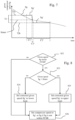
- Fig. 4 is a flow diagram for the operation of Fig. 3 .
- a cycle e.g. a drying or washing cycle
- predefined parameters of the selected cycle are set such as e.g. a specific temperature, compressor speed and/or power.
- step S4 a FCSR avoidance algorithm is applied.
- the FCSR avoidance algorithm may include the transition function as mentioned before for efficiently crossing the FCSR. Details of the FCSR avoidance algorithm are described in the following with respect to Figs. 5 to 8 .
- the FCSR avoidance algorithm determines if a given speed (which is the speed at which the compressor should be operated) is within the FCSR or not and if the speed is within the FCSR, a corrected given speed Sg' is determined.
- the compressor speed is set to Sg' if the given speed is within the FCSR or is set to the given speed Sg if the given speed is not within the FCSR (step S5).
- step S6 it is determined if the refrigerant temperature Tref is below the lower margin T_low or not. As long as Tref is below (or equal to) T_low, steps S3 to S6 may be repeated such that each FCSR, which the compressor speed may cross, can be crossed efficiently by using the transition function.
- step S7 if Tref is above (or equal to) T_low, the control and drive unit may adapted to switch from the operating mode (power control mode 82) to the refrigerant temperature (speed) control mode 84 in which Tref is preferably maintained between T_low and Ttarget by varying the compressor speed.
- the following steps S7 to S12 may be applied in the refrigerant temperature control mode 84 section of Fig. 3 .
- the compressor speed may be maintained at the same value/level, in particular such that Tref is maintained between T_low and Ttarget.
- step S9 a FCSR avoidance algorithm is applied.
- the FCSR avoidance algorithm of step S9 may be equal or different to the FCSR avoidance algorithm of step S4. Details of the FCSR avoidance algorithm are described in the following with respect to Figs. 5 to 8 .
- the FCSR avoidance algorithm determines if a given speed (which is the speed at which the compressor should be operated) is within the FCSR or not and if the speed is within the FCSR, a corrected given speed Sg' is determined.
- the compressor speed is set to Sg' if the given speed is within the FCSR or is set to the given speed Sg if the given speed is not within the FCSR (step S10).
- step S11 it is determined if the refrigerant temperature Tref is below (or equal to) the lower margin T_low or not. If Tref is below (or equal to) the lower margin T_low, the previous compressor (VSC) operating mode may be restored (see: steps S13, S3). If Tref is above (or equal to) the lower margin T_low, it is determined if Tref is below (or equal to) or above (or equal to) Ttarget (see: step S12). If Tref is below (or equal to) Ttarget, given speed Sg is calculated using the above formula of step S8. Steps S8 to S12 may be repeated as long as Tref is between T_low and Tref. If in step S12, Tref is above (or equal to) Ttarget, the compressor speed may be reduced e.g. by 5 %, 10 % or 15% (see: step S14). Then, the method may return back to step S9.
- Figs. 6 and 8 are flow diagrams showing step S4 and/or S9 in more detail. Resonances resulting when crossing the FCSR may have negative effects for the operation of the appliance and/or may be noise annoying for the user of the appliance.
- the FCSR is crossed preferably as fast as possible while ensuring a reliable operation of the heat pump system.
- Fig. 5 is a schematic diagram showing a first transition control function for minimizing the time/duration in which the compressor is driven in a forbidden compressor speed range (e.g. first or second FCSR 72, 74 of Fig. 3 ) during operation of the compressor 46.
- Fig. 6 is a flow diagram representing the method steps of the first transition control function of Fig. 5 .
- the control and drive unit 65, 66 of the appliance 2 may be adapted to implement the first transition control function in which at least one speed control function for crossing the FCSR is specified which is used for retrieving a speed profile for the compressor speed to be applied for crossing the FCSR between the upper 72a and lower limit 72b and/or between the lower 72b and upper limit 72a of the FCSR.
- the FCSR 72 may comprise a predetermined interval speed Sinter which is a speed within the FCSR 72 above the lower limit 72b and below the upper limit 72a. In this case, Sinter is in the center between the upper and lower limit 72a, 72b. In other cases, Sinter may be in the upper half or the lower half of the FCSR 72.
- the given compressor speed Sg is illustrated as a dotted line.
- the given compressor speed Sg may be a calculated speed and/or can be seen as the set speed in view of control theory.
- the given speed Sg may be the desired speed predetermined by the control and drive unit 65, 66, wherein the control and drive unit 65, 66 may be adapted to set the given speed for operating the compressor.
- a gradient of the compressor speed at the time when a current compressor speed Sref arrives at the lower limit 72b or at the upper limit 72a is determined (see: step S16). Based on the gradient, the given speed Sg between the upper and lower limit 72a, 72b is extrapolated (see: Step S17). In Fig. 5 , the extrapolated given speed Sg, i.e. the dotted line between the upper limit 72a and the lower limit 72b, is e.g. a straight line with a negative gradient. If the extrapolated given speed Sg is above (or equal) to the predetermined interval speed Sinter, a corrected speed Sg is set to the upper limit 72a (see: step S18, S20).
- the corrected speed Sg' is set to the lower limit 72b (see: step S18, S19).
- the compressor speed may be set to the corrected speed Sg' when reaching the upper or lower limit 72a, 72b of the FCSR 72.
- the corrected given speed Sg' corresponds to the solid line between the upper and lower limit 72a, 72b.
- the corrected given speed Sg' may be maintained at the upper limit 72a for a duration C1 and may be maintained at the lower limit 72b for a duration C2.
- the durations C1 and C2 are equal in Fig. 5 , but may differ from each other.
- Duration C3 is the duration for changing between the upper and limit lower 72a, 72b or vice versa.
- the speed from the upper limit 72a to the lower limit 72b and/or from the lower limit 72b to the upper limit 72a is changed with a predefined speed gradient, in particular with the highest speed gradient available for the compressor.
- the given speed Sg may be changed from the upper to the lower limit 72a, 72b without maintaining at the upper limit 72a and may be maintained only at the lower limit 72b or the given speed Sg may be maintained only at the upper limit 72a before changing to the lower limit 72b.
- the compressor When the given speed Sg is within the FCSR (or equal to the upper or lower limit of the FCSR), the compressor is preferably operated at the corrected given speed Sg' (solid line in Fig. 5 between upper and lower limit 72a, 72b) and when Sg is above or below the FCSR (or equal to the upper or lower limit of the FCSR), the compressor is preferably operated at the given speed Sg (dotted line in Fig. 5 above and below limits 72a, 72b; see also: step S21).
- control unit 65 of the home appliance calculates the transition function with the values Sg' in the C1 and Cs (also C1' and C2' of Fig. 7 ) and at the moment when the given speed Sg' changes from the upper to the lower limit (or vice versa), transmits the lower limit (or upper limit) as speed Sg' as set value to the compressor inverter 66, which has an internal function for an abrupt speed change from the upper to the lower limit (or vice versa) and applies the speed change with e.g. the maximum gradient.
- Fig. 7 is a schematic diagram showing a second transition control function for avoiding a forbidden compressor speed range during operation of the compressor.
- Fig. 8 is a flow diagram representing the method steps of the second transition control function of Fig. 7 .
- the second transition control function is based on calculating the given speed Sg within the FCSR, wherein the first transition function shown in Figs. 5 and 6 is based on extrapolation of the given speed Sg within the FCSR.
- the given compressor speed Sg is illustrated as a dotted line.
- the given speed Sg may be determined by the control and drive unit 65, 66.
- the calculated given speed Sg i.e. the dotted line between the upper limit 72a and the lower limit 72b, may be a curved line.
- the compressor is preferably operated at the (predetermined) given speed Sg. If the given speed Sg is within the FCSR 72, and is below (or equal) to the predetermined interval speed Sinter, the corrected speed Sg' is set to the lower limit 72b (see: steps S23, S24). If the given speed Sg is within the FCSR 72, and is above (or equal) to the predetermined interval speed Sinter, the corrected speed Sg' is set to the upper limit 72a (see: steps S23, S25). The corrected given speed Sg' corresponds to the solid line between the upper and lower limit 72a, 72b.
- the corrected given speed Sg' may be maintained at the upper limit 72a for a duration C1' and may be maintained at the lower limit 72b for a duration C2'.
- the durations C1' and C2' are longer than C1 and C2.
- C1' is less than C2', i.e. the compressor speed is maintained at the lower limit 72b for a longer time period than at the upper limit 72a.
- Duration C3' is also less than C3 of Fig. 5 , i.e. the change of the speed from the upper limit 72a to the lower limit 72b or vice versa has a higher speed gradient than compared to Fig. 5 .
- the compressor When the given speed Sg is within the FCSR 72 (or equal to the upper or lower limit of the FCSR 72), the compressor is preferably operated at the corrected given speed Sg' (solid line in Fig. 7 between upper and lower limit 72a, 72b) and when Sg is above or below the FCSR (or equal to the upper or lower limit of the FCSR), the compressor is preferably operated at the given speed Sg (dotted line in Fig. 7 above and below limits 72a, 72b).
- transition functions applied in Figs. 5 and 7 result in a minimized duration of the compressor speed being within the FCSR as compared to the duration which would result if the compressor speed would have controlled with the otherwise applied compressor control function, which is the gradient with the lower value (as compared to the transition) in Fig. 5 and which is the above formula for Sg(t) in Fig. 7 .
- Fig. 9 is a schematic diagram showing another example for crossing a forbidden compressor speed range during operation of the compressor.
- the given compressor speed Sg is illustrated as a dotted line.
- the given speed Sg may be determined by the control and drive unit 65, 66.
- the compressor speed is operated at the given speed Sg (which may be calculated by the above formula) above the upper limit 72a of the FCSR 72.
- Sg which may be calculated by the above formula
- the normal control theory of the compressor speed may be suspended and the compressor speed is at least temporally kept at the upper limit 72a of the FCSR.
- Suspending the normal control theory means that the compressor speed at which the compressor is to be operated is not set to the calculated given speed Sg, but the corrected compressor speed Sg' is set to the upper (or lower) limit of the FSCR.
- the normal control theory (feed-back control) of the compressor speed is re-activated (end of suspension). I.e. the compressor speed is kept at the upper (or lower) limit until the control and drive unit detects that the theoretical (extrapolated) compressor speed arrives at the lower (or upper) limit.
- the jump is a result of the refrigerant temperature Tref(t) being high or closer to Ttarget than would have been under the normal feedback-control. Namely during keeping the compressor speed at the upper (or lower limit) the temperature of the refrigerant arrives at a higher (lower) value than if the normal control theory would be applied. For compensating the higher (lower) temperature value, after reactivation of the normal control theory i.e. after the speed jump, the compressor speed may be set to a value which is below the lower limit (above the upper limit) of the FCSR.
Priority Applications (1)
| Application Number | Priority Date | Filing Date | Title |
|---|---|---|---|
| EP22170545.2A EP4268699A1 (de) | 2022-04-28 | 2022-04-28 | Haushaltsgerät mit wärmepumpenanordnung und verfahren zum betrieb des haushaltgerätes |
Applications Claiming Priority (1)
| Application Number | Priority Date | Filing Date | Title |
|---|---|---|---|
| EP22170545.2A EP4268699A1 (de) | 2022-04-28 | 2022-04-28 | Haushaltsgerät mit wärmepumpenanordnung und verfahren zum betrieb des haushaltgerätes |
Publications (1)
| Publication Number | Publication Date |
|---|---|
| EP4268699A1 true EP4268699A1 (de) | 2023-11-01 |
Family
ID=81392895
Family Applications (1)
| Application Number | Title | Priority Date | Filing Date |
|---|---|---|---|
| EP22170545.2A Pending EP4268699A1 (de) | 2022-04-28 | 2022-04-28 | Haushaltsgerät mit wärmepumpenanordnung und verfahren zum betrieb des haushaltgerätes |
Country Status (1)
| Country | Link |
|---|---|
| EP (1) | EP4268699A1 (de) |
Citations (4)
| Publication number | Priority date | Publication date | Assignee | Title |
|---|---|---|---|---|
| US20120186305A1 (en) * | 2009-10-27 | 2012-07-26 | Panasonic Corporation | Laundry dryer and washer dryer |
| EP2733257A1 (de) * | 2012-11-16 | 2014-05-21 | Electrolux Home Products Corporation N.V. | Verfahren zum Betrieb einer Wäschebehandlungsvorrichtung und Wäschebehandlungsvorrichtung |
| EP2746458A1 (de) * | 2012-12-24 | 2014-06-25 | Electrolux Home Products Corporation N.V. | Verfahren zur Steuerung eines Wäschetrockners und entsprechender Wäschetrockner |
| EP3239387A1 (de) * | 2016-04-26 | 2017-11-01 | Electrolux Appliances Aktiebolag | Verfahren zum betreiben einer wäschetrocknervorrichtung und wäschetrocknervorrichtung |
-
2022
- 2022-04-28 EP EP22170545.2A patent/EP4268699A1/de active Pending
Patent Citations (4)
| Publication number | Priority date | Publication date | Assignee | Title |
|---|---|---|---|---|
| US20120186305A1 (en) * | 2009-10-27 | 2012-07-26 | Panasonic Corporation | Laundry dryer and washer dryer |
| EP2733257A1 (de) * | 2012-11-16 | 2014-05-21 | Electrolux Home Products Corporation N.V. | Verfahren zum Betrieb einer Wäschebehandlungsvorrichtung und Wäschebehandlungsvorrichtung |
| EP2746458A1 (de) * | 2012-12-24 | 2014-06-25 | Electrolux Home Products Corporation N.V. | Verfahren zur Steuerung eines Wäschetrockners und entsprechender Wäschetrockner |
| EP3239387A1 (de) * | 2016-04-26 | 2017-11-01 | Electrolux Appliances Aktiebolag | Verfahren zum betreiben einer wäschetrocknervorrichtung und wäschetrocknervorrichtung |
Similar Documents
| Publication | Publication Date | Title |
|---|---|---|
| AU2013346977B2 (en) | Method of operating a heat pump laundry dryer and heat pump laundry dryer or heat pump washing machine having drying function | |
| AU2013346941B2 (en) | Method of operating a heat pump laundry dryer and heat pump laundry dryer or heat pump washing machine having drying function | |
| US9435069B2 (en) | Appliance for drying laundry | |
| US9372031B2 (en) | Appliance for drying laundry | |
| US10351989B2 (en) | Appliance for drying laundry with enhanced operation flexibility | |
| EP2935686B1 (de) | Verfahren zur steuerung eines wärmepumpensystems für einen wäschetrockner und entsprechender wäschetrockner | |
| EP3019655B1 (de) | Wärmepumpentrockner mit verbesserter, felxiblerer betriebsweise | |
| EP2920355A1 (de) | Wäschebehandlungsvorrichtung mit einer wärmepumpe und verfahren für den betrieb der wäschebehandlungsvorrichtung mit der wärmepumpe | |
| EP3124680B1 (de) | Verfahren zur anpassung von betriebsparametern beim trocknen in einem wärmepumpentrockner | |
| AU2013346825B2 (en) | Heat pump laundry treatment apparatus and method of operating a heat pump laundry treatment apparatus | |
| EP3124689B1 (de) | Verfahren zum betreiben eines wärmepumpentrockners | |
| EP3124690A1 (de) | Verfahren zum betreiben eines wärmepumpentrockners | |
| AU2016200878A1 (en) | Method of Operating a Laundry Treatment Apparatus Using Operation State Information | |
| EP4268699A1 (de) | Haushaltsgerät mit wärmepumpenanordnung und verfahren zum betrieb des haushaltgerätes | |
| CN107794727B (zh) | 衣物干燥机 | |
| KR20220114693A (ko) | 의류처리장치 및 이의 제어방법 | |
| EP2843124A1 (de) | Vorrichtung und Verfahren zum Betrieb eines Kühlgebläses in einer Wäschebehandlungsvorrichtung mit Wärmepumpe | |
| CN110219152B (zh) | 带有热泵的衣物干燥设备 | |
| JPH11216295A (ja) | 洗濯機 |
Legal Events
| Date | Code | Title | Description |
|---|---|---|---|
| PUAI | Public reference made under article 153(3) epc to a published international application that has entered the european phase |
Free format text: ORIGINAL CODE: 0009012 |
|
| STAA | Information on the status of an ep patent application or granted ep patent |
Free format text: STATUS: THE APPLICATION HAS BEEN PUBLISHED |
|
| AK | Designated contracting states |
Kind code of ref document: A1 Designated state(s): AL AT BE BG CH CY CZ DE DK EE ES FI FR GB GR HR HU IE IS IT LI LT LU LV MC MK MT NL NO PL PT RO RS SE SI SK SM TR |